1
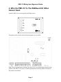
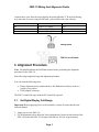
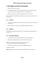
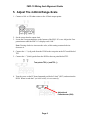
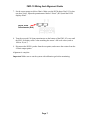
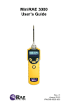
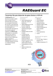
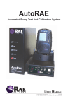
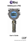
FMC-10 Controller
Wiring And Alignment Guide
Rev. A
November 2010
P/N F05-4012-000
FMC-10 Wiring And Alignment Guide
Contents
1. Wire The FMC-10 For AC Power .................................................................................. 1
2. Wire the FMC-10 To The RAEGuard Or Other Sensor Head........................................ 2
3. Alignment Procedure ...................................................................................................... 3
3.1.
Set Digital Display Full-Range ........................................................................... 3
3.2.
Set Full-Scale Maximum Value .......................................................................... 4
4. Set High/Low Alarm Thresholds .................................................................................... 5
4.1.
Low Set ............................................................................................................... 5
4.2.
High Set .............................................................................................................. 5
4.3.
Normalize Settings .............................................................................................. 5
5. Adjust The 4-20mA Range-Scale ................................................................................... 6
RAE Systems Contacts ....................................................................................................... 8
Important!
Consult the FMC-10 User’s Guide for operational information. This guide is not intended
as an operational guide. It is intended only for installation and alignment. If you do not
have a copy of the FMC-10 User’s Guide, it is available in PDF form from the RAE
Systems website at www.raesystems.com.
© Copyright 2010 RAE Systems by Honeywell
FMC-10 Wiring And Alignment Guide
1. Wire The FMC-10 For AC Power
Connect power wires from an AC source to the 3-pole power block. Slip the stripped end
of each wire into the receptacle on the block and tighten its screw. Connect as follows:
Label:
Meaning:
AC wires:
E
L
N
Earth
Ground
Live
Hot
Neutral
Neutral
Wiring block
FMC-10 circuit board
Note: Refer to the FMC-10 user’s manual for other configurations.
Important! Before applying power to the controller, connect all sensor heads to the
selected channel.
Once the block is wired for AC power, plug the block into its mating receptacle on the
PC board.
Page 1
FMC-10 Wiring And Alignment Guide
2. Wire the FMC-10 To The RAEGuard Or Other
Sensor Head
Open the FMC-10 by removing the four Philips screws.
The printed circuit board with all connection points is now visible.
Note: The two potentiometers labeled Zero and Cal are accessed through two holes in the
bottom of the FMC-10 enclosure. All other potentiometers and test points are located on
the printed circuit board.
Page 2
FMC-10 Wiring And Alignment Guide
Connect three wires from the sensor head to the points labeled P Y W in the following
way (note that if you are using a RAEGuard, you can follow the color scheme):
FMC-10 Label
Sensor Wire
RAEGuard Wire
W
Y
P
Positive (+) supply
4-20mA signal output
Negative (-) supply
Red
Blue
Black
Wiring block
FMC-10 circuit board
3. Alignment Procedure
Note: You should calibrate the RAEGuard sensor before performing the alignment
procedure for the FMC-10.
With all wiring completed, begin the alignment procedure.
You will need the following tools:
•
•
Plastic alignment tool (recommended) or fine flathead screwdriver such as a
jeweler’s screwdriver
DVM (digital voltmeter)
The FMC-10 should be open with the PC board fully exposed.
3.1. Set Digital Display Full-Range
Important! Before applying power to the controller, connect all sensor heads to the
selected channel.
1. Apply power to the FMC-10.
2. Use an alignment tool to adjust the Zero potentiometer (located on the bottom of the
FMC-10) so that the FMC-10’s display reads 000 (or 20.9 for oxygen sensors).
Page 3
FMC-10 Wiring And Alignment Guide
3. Turn on the DVM.
4. Connect the “+” (red) probe from the DVM to the test point on the PC board labeled
TP4.
5. Connect the “-” (black) probe from the DVM to the test point labeled TP5.
Test points TP4 (+) and TP5 (-)
6. While monitoring the display on the DVM, use the alignment tool to turn the recessed
screw labeled Zero on the outside of the FMC-10 until the DVM reading is 0.5 volts.
Note: Turning clockwise increases the value, while turning counterclockwise decreases
it.
3.2. Set Full-Scale Maximum Value
Now set the full-scale maximum value to match your sensor head’s detection range.
1. Use the screwdriver to turn the screw on the board-mounted potentiometer (RV2)
labeled “DPM” while watching the display on the front of the FMC-10.
Use alignment tool or
small screwdriver
to adjust
2. Adjust it until the value shown in the FMC-10’s display reads the same as the fullscale output of the sensor head (for example, 1000, 500, 20, etc.).
3. Disconnect the DVM’s probes from the test points.
Note: Turning clockwise increases the value, while turning counterclockwise decreases
it.
Page 4
FMC-10 Wiring And Alignment Guide
4. Set High/Low Alarm Thresholds
1. Adjust the sensor to put out 4mA.
2. Press and hold the FMC-10 Alarm set button on the circuit board until the alarm
beeps and the Low alarm LED on the FMC-10’s front panel glows.
3. When you hear the beep (and the Low LED glows), release the switch.
Note: Establish low and high alarm thresholds you want from the sensor head (such as
20, 500, etc.).
4.1. Low Set
1. Adjust the Zero potentiometer until the FMC-10’s display shows the low alarm value
(such as 200).
2. Press the Alarm Set button once, and the high alarm LED should glow.
4.2. High Set
Adjust the Zero potentiometer until the FMC-10’s display shows the high alarm value
(such as 500).
4.3. Normalize Settings
1. Press the Alarm set button. Both the High and Low LEDs should glow.
2. Adjust the Zero potentiometer to show 000 in the FMC-10 display.
Note: If you are using an oxygen detector, set the value to 20.9.
For toxics and PID sensors, the reading should be 000.
3. Press the Alarm set button again, and alarm LEDs should turn off.
Alignment is complete.
Important! Make sure to test the system with calibration gas before monitoring.
Page 5
FMC-10 Wiring And Alignment Guide
5. Adjust The 4-20mA Range-Scale
1. Connect a 100- to 250-ohm resistor to the 4-20mA output points.
2. Set the sensor head to output 4mA.
3. Locate the Zero potentiometer on the bottom of the FMC-10’s case. Adjust the Zero
potentiometer until the FMC-10’s display reads “000.”
Note: Turning clockwise increases the value, while turning counterclockwise
decreases it.
4. Connect the “+” (red) probe from the DVM to the test point on the PC board labeled
TP2.
5. Connect the “-” (black) probe from the DVM to the test point labeled TP3.
Test points TP2 (+) and TP3 (-)
6. Turn the screw on the PC-board-mounted pot labeled “4mA” (RV3) and monitor the
DVM. When it reads 4mV (or 0.004 volts), it is set correctly.
Adjust 4mA
Potentiometer (RV3)
Page 6
FMC-10 Wiring And Alignment Guide
7. Set the sensor output to deliver 20mA. Make sure the DVM shows 20mV. If it does
not show 20mV, adjust the potentiometer labeled “20mA” (RV4) until the DVM
displays 20mV.
Adjust 20mA
Potentiometer (RV4)
8. Turn the recessed Cal Span potentiometer on the bottom of the FMC-10’s case until
the FMC-10 display reads a value matching the sensor’s full-scale value (such as
1000 or 20, etc.).
9. Disconnect the DVM’s probes from the test points, and remove the resistor from the
4-20mA output points.
Alignment is complete.
Important! Make sure to test the system with calibration gas before monitoring.
Page 7
FMC-10 Wiring And Alignment Guide
RAE Systems Contacts
RAE Systems by Honeywell
World Headquarters
3775 N. First St.
San Jose, CA 95134-1708 USA
Phone: +1 408.952.8200
Fax: +1 408.952.8480
E-mail: [email protected]
Web Site: www.raesystems.com
RAE Systems Technical Support
Monday through Friday, 7:00AM to 5:00PM Pacific Time
Phone: +1.408.952.8461
Email: [email protected]
RAE Systems Europe ApS
Kristinehøj 23 A
DK-2770 Kastrup
Denmark
Phone: +45 86 52 51 55
Fax:
+45 86 52 51 77
[email protected]
[email protected]
[email protected]
Web: www.raesystems.eu
RAE Systems UK Ltd
D5 Culham Innovation Centre
Culham Science Centre
Abingdon, Oxon OX14 3DB
United Kingdom
Phone: +44 1865408368
Fax: +44 1235531119
Mobile: +44 7841362693
Email: [email protected]
Page 8
FMC-10 Wiring And Alignment Guide
RAE Systems France
336, rue de la fée des eaux
69390 Vernaison
France
Phone: +33 4 78 46 16 65
Fax: +33 4 78 46 25 98
Email: [email protected]
Web: www.raesystems.fr
RAE BeNeLux BV
Rijndal 20
2904 DC Capelle a/d IJssel
Phone: +31 10 4426149
Fax: +31 10 4426148
Email: [email protected]
Web: www.rae.nl
RAE Systems Spain, s.l.
Av. Remolar, 31
08820 El Prat de Llobregat
Spain
Phone: +34 933 788 352
Fax: +34 933 788 353
Mobile: +34 687 491 106
Email: [email protected]
Web: www.raespain.com
RAE Systems Middle East
LOB 7, Ground Floor, Office 19,
Jebel Ali Free Zone
Dubai, United Arab Emirates
Phone: +971.4.887.5562
Email: [email protected]
RAE Systems (Hong Kong) Ltd.
Room 8, 6/F, Hong Leong Plaza
33 Lok Yip Road
Fanling, N.T, Hong Kong
Phone: +852.2669.0828
Fax: +852.2669.0803
Email: [email protected]
Page 9
RAE Systems by Honeywell
World Headquarters
3775 N. First St.
San Jose, CA 95134-1708 USA
Phone: 408.952.8200
Toll-Free: 888.723.4800
Fax: 408.952.8480
E-mail (sales support): [email protected]
Web Site: www.raesystems.com
Technical Support
Phone: 408.952.8461 (Mon-Fri, 7AM-5PM, PST)
Email: [email protected]
Training
Courses: www.raesystems.com/support
Email: [email protected]
Product Registration
www.raesystems.com/support/product-registration
RAE Systems Europe
Kirstinehøj 23A, DK-2770 Kastrup • Denmark
Phone: +45.8652.5155 • Fax: +45.8652.5177
Web: www.raesystems.eu • Email: [email protected]
RAE Systems (Hong Kong) Ltd.
Units 1516-18, 15/F, Delta House, 3 On Yiu Street
Shatin, N.T. Hong Kong
Phone: +852.2669.0828 • Fax: +852.2669.0803
Web: www.raesystems.com.hk • Email: [email protected]
RAE Systems Middle East
LOB 7, Ground Floor, Office 19, Jebel Ali Free Zone
Dubai, United Arab Emirates
Email: [email protected] • Phone: +971.4.887.5562
Rev. A
November 2010
P/N F05-4012-000