1
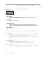
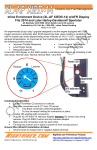
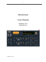
1
NoiseLesser
User Manual
Software v2.1
Manual v2.1
© PA0SIM June 2015
2
Index
1 General Description .................................................................................. 3
2 Freeware .................................................................................................... 3
3 Installation ................................................................................................. 3
4 Controls, Switches and Display Indications ........................................... 4
4.1
General Controls and Indicators .................................................................................... 4
4.2
Noise Reduction Settings A/B controls ........................................................................ 5
5 Adjusting the Controls and Sliders ......................................................... 6
6 Selecting Input and Output Device(s) ...................................................... 6
7 Run and Stop ............................................................................................. 7
8 Suggestions for Use ................................................................................. 7
9 Using VAC Virtual Audio Cable ................................................................ 7
10
Latency and # buffers............................................................................. 8
11
T/R switching .......................................................................................... 8
12
Known bug solved .................................................................................. 8
13
Audio Feedback ...................................................................................... 8
14
Software Programming .......................................................................... 9
14.1
DSP in Simulink ............................................................................................................ 9
14.2
GUI in Labview .............................................................................................................. 9
14.3
Combining Labview and Simulink .............................................................................. 9
15
Change History ....................................................................................... 9
© PA0SIM June 2015
3
1
General Description
The noise reduction is focused on finding the best setting for the actual band conditions. It is
therefore equipped with two sets of controls. This enables keeping one set as a reference for
the other set. By switching between both settings the preferred setting for the best
readability of the signal can be found.
Several algorithms are implemented for CW and speech. All algorithms are based on selective
filtering. Noise cannot be subtracted from the total signal, because it is not predictable. You
don’t know what to subtract. By selective filtering the noise from unwanted frequencies is
attenuated. This is very effective, provided you know the frequency components you do
need.
2
Freeware
Software and Manual are freeware for private and non-commercial use in educational
institutions only. Permission is granted to use the information and the software for private
and non-commercial use in educational institutions only. Any commercial or other
application, distribution and sale is prohibited.
I will not accept responsibility for any damage to your equipment through the use of this
information and the software or as a result thereof.
Al rights reserved © PA0SIM.
3
Installation
The installation is simple. Unpack the files in a directory of choice.
Run the executable by double clicking or making a shortcut on the desktop.
The first time it will ask to install the LabVIEW Run-Time Engine 2013 and will show the link to
the correct page (http://www.ni.com/download/labview-run-time-engine-2013/4059/en/).
These dll’s are needed to be able to run the Labview executables. The GUI of the noise
reduction is programmed in Labview.
If you already run a time synchronization like Dimension 4, it is advisable to disable the NI
Time Synchronization Service via MSCONFIG.
It is tested on Windows XP, 7 and 8.1.
It can be necessary to check the settings of the sound card e.g. select ‘Allow applications to
take exclusive control of this device'.
© PA0SIM June 2015
4
4
Controls, Switches and Display Indications
4.1
General Controls and Indicators
[Start →] Button
Starts running the program. The S-meter will jump to maximum and return to S3.
This knob is not visible when the program runs.
[Stop] Button
Stops running the program.
[Input Device] Select
Selects the input device (0-20). Input device 0 is the default Windows recording
device. Has to be selected before starting the program. Has no effect when running.
[Channel] Select
Select Left (0) or Right (1) channel, before and while running.
[Output Device] Select
Selects the output device (0-20). Output device 0 is the default Windows playback
device. Has to be selected before starting the program. Has no effect when running.
[# buffers] select
Minimum 1 and maximum 24 output buffers can be selected. Has to be selected
before starting the program. Has no effect when running.
For slower PC/laptops select a higher number if needed. One buffer equals 125msec
in time.
[S-meter] Indicator
Indicates the signal strength in S points (6dB), S9 is 50mV.
Red indicator is the signal strength, the blue indicator is the AGC knee level.
[Magnitude] Indicator
The spectrum of the input signal (red) and the processed signal (green) are displayed
from 0Hz to 4kHz. Magnitude range is from -120dB to 0dB (dBV).
© PA0SIM June 2015
5
[Processing Timer] Indicator
The time needed to process one input buffer in msec.
The computer is fast enough if it indicates less than 25msec.
If it indicates 0, the processing has stopped.
[Buffers Processed] Indicator
Each 125msec a buffer is processed. The number of processed buffers is displayed.
If it stops counting, the program has stopped running.
[Input Gain] Control
An extra gain control to set the input level. Advise: keep the noise level below S9.
[Output AF Level] Control
An extra AF level control to set the audio level.
[Mute] Button
Mutes the audio output.
4.2
Noise Reduction Settings A/B controls
[Mode] Switch
Selects Noise Reduction for CW or Speech (SSB/AM/FM)
[Select Settings] Switch
Selects between setting A and setting B. The <Enter> key toggles this switch.
[Roofing Filter A/B] Button
Enables a 600Hz Bandpass Roofing Filter at the input of the CW processing.
[CW NR/BPF A/B] Button
Enables the CW Noise Reduction.
[nLMS1/nLMS2/FFT/BPF A/B] Select switch
Selects the processing used by the CW Noise Reduction:
- nLMS1 is a normalized Least Mean Squares adaptive filter
- nLMS2 is a “boosted” normalized Least Mean Squares adaptive filter
- FFT is a NR based on the Fast Fourier Transform (FFT)
- BPF is a narrow (35Hz) brick-wall bandpass filter using the FFT
For best performance of the nLMS NR use an input signal bandwidth >=500Hz
[CW NR Level A/B] Control
Controls the level of Noise Reduction for the nLMS and FFT NR.
[Fc A/B] Setting
Sets the center frequency of both the BPF and the Audio Peak Filter.
© PA0SIM June 2015
6
[APF A/B] Button
Enables the 30Hz Audio Peak Filter (APF).
[SSB NR A/B] Button
Enables the SSB Noise Reduction.
[Auto Notch A/B] Switch
Enables the Auto Notch (Beat-cancelling) using the Noise Reduction. The Auto Notch
can also be effective for stable QRM sources.
[SSB NR Level A/B] Control
Controls the level of Noise Reduction.
[Manual Gain A/B] Control
Controls the gain after processing. Can be used instead of the AGC.
[AGC A/B] Button
Enables the Automatic Gain Control (AGC).
[AGC Knee A/B] Control
Sets the knee level of the AGC in S-points. This level is indicated on the S-meter by
the blue indicator.
[AGC Speed A/B] Control
Sets the speed of the AGC (0=slow, 1=fast)
5
Adjusting the Controls and Sliders
The buttons and switches are operated by clicking with the left mouse button.
The sliders can also be trimmed by clicking with the left mouse button on the corresponding
number/digit and using the up/down arrow keys on the keyboard.
The Select Settings switch can also be toggled using the <Enter> key on the keyboard.
6
Selecting Input and Output Device(s)
The input/output audio devices have to be selected before start. One out of 21 devices can
be selected. Device number 0 is always the default device. If not sure about device
number(s) it can help to set the playback or recording device you want to use default in the
Windows environment. The left or right channel (0/1) can be selected while running.
The sample rate of the input/output device is 48kHz and using 16 bits.
© PA0SIM June 2015
7
7
Run and Stop
The program starts by activating the → button. It has to be stopped using the Stop button.
8
Suggestions for Use
The output AF level can best be set to a convenient level after enabling the AGC.
The AGC is not a RMS detector, but a peak voltage detector.
Keep input noise level preferable >S3 (0dB Input Gain).
The processing runs at 8kHz sample frequency, the audio bandwidth is fixed by a roofing filter
at 125Hz-2900Hz.
The AGC knee (threshold) setting is the primary crucial AGC control and can be regarded as
an RF gain setting. The AGC knee limits the gain for signal levels lower than the AGC knee
voltage. So all signals lower than the knee voltage have the same constant gain. The AGC
knee voltage is set in S-points (blue indicator on S meter).
If the knee voltage is set too low all signals and noise are amplified to the same maximum
level. The result is that after noise reduction also the reduced noise is amplified again to the
maximum level. This in effect neutralizes the noise reduction, because the noise and the
signal have the same level again.
The next two settings are a good starting point:
1) set the AGC knee about 1 S point lower than the noise level of the unprocessed noise, AGC
speed at default.
You expect a signal always to be stronger than the noise. Only stronger signals need an AGC
to control the output level. Now all noise lower than the knee have the same constant gain.
The AGC is inactive below the knee. Weaker noise now stays weaker, so also the reduced
noise after enabling the NR stays weaker.
2) switch off the NR AGC and use the RF gain and AGC of the receiver.
Set the RF gain just a little bit higher than the noise level, so a weak signal does not activate
the AGC of the receiver. Set the manual gain in the NR to a convenient level without the noise
reduction enabled. Then switch on the noise reduction.
The APF (30Hz) and BPF (35Hz) filters have the same center frequency Fc and can be used at
the same time. When using these filters the frequency has to be tuned very accurately.
9
Using VAC Virtual Audio Cable
The VAC makes it possible to interface with SDR, audio files and other audio software.
http://software.muzychenko.net/eng/vac.htm
Audacity (free) is a much recommended program to use in combination with VAC.
http://audacity.sourceforge.net/?lang=en
Audio files can be adapted for use with the Noise Reduction. E.g. sample rate conversion to
48000Hz can be handled by Audacity. The accompanying mp3 files can be used for test using
Audacity. Using the shift/space key combination runs the files continuously repeated.
© PA0SIM June 2015
8
10
Latency and # buffers
The overall latency or delay is the sum of the worst case processing latency and the worst
case buffering latency needed for uninterrupted audio in a Windows environment.
The selected number of output buffers indicates the time that can be bridged when the
Windows operating system is retarding the Noise Reduction. One buffer equals 125msec.
Retarding times longer than the total output buffering will cause drop outs in the audio
output. If the drop outs remain, a restart of the Noise Reduction is necessary.
In order to have the same delay for all combinations of processing, the processing delay is
kept constant and equal to the sum of all consecutive processing delays. The FFT accounts for
about 150msec of the total 180msec processing delay.
11
T/R switching
The latency in the audio is too large for QSK CW application.
A hardware switching box can help.
In this box the audio output of the computer and the audio output of the transceiver are
switched by the CW keying.
To bridge the latency, switching back to the computer audio can be delayed.
In this way QSK is maintained. NR comes active again after the delayed switching.
12
Known bug solved
The audio input/output buffering is not well implemented in Labview by National Instruments!
It is an old known bug in Labview and no stable audio is feasible. In the previous version 1.0
an error message (error 4823) was displayed when the program stopped (crashed) as a result
of other process activities, especially on slower/older computers.
WaveIO software (VI’s) designed by C. Zeitnitz solved it and makes the sound card applicable
for Labview.
However Labview does not support automatic resolving overflow and underrun in the
buffering.
13
Audio Feedback
The gain in the processing can be substantial.
Feedback (cross talk) from the audio output lines to the audio input lines should be
prevented. It can cause echo effects or oscillation effects.
© PA0SIM June 2015
9
14
Software Programming
14.1
DSP in Simulink
Matlab/Simulink is very well suited for playing with Digital Signal Processing. It support the
development of DSP for e.g. Noise Reduction. Simulink makes it possible to interactively play
with DSP as with an analogue or digital electronic schematic. It uses functional blocks to make
up the processing. Each block is unambiguously and clearly described. It support a lot of ways
to measure and test while developing. Such a schematic made out of blocks is needed
because a lot of processing is going on in parallel and in a data flow, like in an analogue or
digital electronic circuit. It helps keeping an overview of what is programmed. You don’t need
to know how to program DSP software, you can stay focused on the functionality. Simulink in
this way strongly supports developing DSP.
For home and personal use, there is a low cost version available. See also:
http://nl.mathworks.com/pricing-licensing/index.html?intendeduse=home
http://nl.mathworks.com/products/matlab-home/
http://nl.mathworks.com/hardware-support/rtl-sdr.html
14.2
GUI in Labview
Labview is very well suited for designing Graphical User Interfaces. It also can do DSP using
blocks, but the blocks are less well described. By using both you can use the best of Labview
and Simulink.
14.3
Combining Labview and Simulink
It is possible to make a dll from the Simulink DSP model and to call it in a Labview program.
This dll together with the executable from the Labview program makes the total packages.
15
Change History
February 2015 Beta 1.0, 2.0 and 2.1.
Beta 2.0/2.1:
Low Pass Filtering added at output after upsampling.
Both LPF at input and output 3.5kHz and 6th order IIR.
Changed S-meter to 0-14 S-points.
March 2015 v1.0
Editorial changes.
Improved downsampling and upsampling filtering. LPF at input and output is 3.5kHz using
Multirate Polyphase filtering.
April 2015 v2.0
Error 4823 solved, number of output buffers selectable.
Maximum number input/output devices increased to 21.
SSB NR improved. CW FFT NR adjusted and improved.
June 2015 v2.1
Annoying and very sneaky bug found in calling the Simulink dll in Labview.
SSB Noise Reduction revised.
© PA0SIM June 2015