1
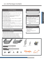
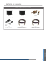
Dear Valued Customer,
Thank you for choosing Listen! All of us at Listen are dedicated to providing
you with the highest quality products available. We take great pride in their
outstanding performance because we care that you are completely
satisfied. That’s why we independently certify them to the highest quality
standards and back them with a limited lifetime guarantee. We stand ready
to answer any questions you might have during installation or in the operation
of our products. Should you experience any problems whatsoever with your
Listen products, we are ready to help you in any way we can with prompt,
efficient customer care. Because at Listen, it’s all about you! And should you
have any comments on how we might improve our products or our
service, we’re here to listen.
Here’s how to reach us:
+1.801.233.8992
+1.800.330.0891 North America
+1.801.233.8995 fax
[email protected]
www.listentech.com
Thank you and enjoy your listening experience!
Best regards,
Russell Gentner and the Listen Team
• In the few instances where repairs were needed, 99% of all clients indicated that they were happy with
repair turn-around-times and 85% of the time, clients were without their product for less than 10 days!
• Overall client satisfaction of working with Listen was rated 4.8 out of 5.
• “Please continue with your excellent attitude toward customer satisfaction. You guys are great!”
• “I’ve never had such good service from any company. Keep up the good work!”
• “You stand behind your product wonderfully.”
Assistive Listening • Language Interpretation • Soundfield • Tour Group • Conferencing
Table of Contents
LA-122 Table of Contents
Package Contents
Package Contents
3
Architectural Specifications
4
Specifications
4
Setup Instructions
5
Dipole Antenna Mounting Options
8
Monopole Antenna Mounting Options
12
Optional Accessories
15
Troubleshooting
16
Compliance Notice/ FCC Statement
17
Warranty/ Contacting Listen
18
Notes
19
Specifications
Setup Instructions
Information
1
LA-122 Package Contents
LA-122 Contents
Listen Part Number
Use With:
LT-800-072 Stationary Transmitter
LT-800-216 Stationary Transmitter
LT-803-072 Stationary 3-Channel FM Transmitter (72 MHz)
LR-100-072 Stationary Receiver/Power Amplifier
LR-100-216 Stationary Receiver/Power Amplifier
LR-600-072 Wireless FM Receiver/Speaker (72MHz)
LR-600-216 Wireless FM Receiver/Speaker (216MHz)
LA-122 Universal Remote Antenna
Package Contents
• Wall/Electrical Box Mounting Plate
• Mounting Bracket
• Antenna Module and 25 ft. (7.6 m) RG58 coaxial cable
with BNC Connectors
• Telescoping antennas (2 for both 72 and 216 MHz)
• Flexible antennas (2 for both 72 and 216 MHz)
• Ground Plane and Shorting Plate
• Mounting Hardware:
(4) #6-32 Machine Screws - used to mount to a single or
dual gang duplex box
(4) #8-32 Machine Screws - used to mount to a square or
hex junction or light box
(4) #8 Sheet Metal Screws - used to mount to metal or
wood, or for use with dry anchors
(4) Dry Anchors - used to mount to drywall, concrete, plaster, brick, or masonry
(2) Hex Kep Nuts (#10-32) and one (1) Fiber Washer - used
for mounting flexible antennas to the Antenna Module,
and for grounding purposes
Optional Accessories
LA-127 RG58 BNC Cable Connector
LA-128 RG8 BNC Cable Connector
LA-112 RG58 Coaxial Cable
LA-113 RG8 Low Loss Coaxial Cable
LA-390 RG8/50 Ohm Low Loss
Preassembled Cable
LA-391 RG58/50 Ohm Preassembled
Cable
Mounting Options
•Wall Mount (to your electrical box)
Direct Wall Mount
•Ceiling Mount
In-Wall or In-Ceiling Mount
Mast Mount
Mounting Bracket
Grounding Base
Wall/Electrical Box
Mounting Plate
Shorting Plate
Antenna Module
Telescoping Antennas 216 MHz
Telescoping Antennas 72 MHz
Machine Screw
Dry Anchors
Tapping Screws
Hex Kep Nut
Fiber Washer
Flexible Antennas 72 MHz
Flexible Antennas 216 MHz
3
LA-122 Specifications
Architectural Specifications
The Universal Antenna Kit shall be capable of operating from 72.0 to 76.0 MHz with a center
frequency of 73.5 MHz and from 216.0 to 217.0 MHz with a center frequency of 216.5 MHz. The
kit shall include the necessary mounting hardware to mount the antenna on a single or dual
electrical box, directly on a wall, on a ceiling electrical box or on a flat surface. The antenna
shall have a BNC connector and the kit shall come with 25 ft. (7.6 m) of RG58 coax with BNC
connectors. The kit shall include rigid and flexible antenna radials. The Listen LA-122 Universal
Antenna Kit is specified.
Specification
Specifications
Center Frequencies
Antenna Types
Antenna Segment Lengths
Specifications
Antenna Gain
Dipole Vertical Clearance
Connector
Coax Provided
Mounting Options
Mounting Hardware
Mounting Bracket Dimensions
Mounting Plate Dimensions
Shipping Box Dimensions
Weight
LA-122
73.50 MHz and 216.50 MHz
Monopole and Dipole
(same for both rigid and flexible antennas) 72 MHz: 39.25
in (1.0 m); 216 MHz: 12.25 in. (31.1 cm)
Unity
72 MHz: 79.75 in. (2.03 m); 216 MHz: 25.75 in.
(65.4 cm)
Standard BNC
25 ft. (7.6 m) RG58 with BNC connectors
Wall mount, dual and single electrical box, ceiling
electrical box, horizontal surface mount (such as on top
of a rack), ceiling/ inverse mounting, flexible mounting
in-wall or in-ceiling and mast or conduit mount
Provided. Includes self-tapping sheet metal screws,
drywall anchors, and all hardware required to mount to
electrical boxes. Does not include hardware required to
mount to a mast (available at most hardware stores)
4.5 in. (11 cm) wide x 7.0 in. (18 cm) deep x 2.5 in.
(6.4 cm) high
4.48 in. (11.4 cm) x 4.55 in. (11.6 cm)
2.76 in. (70 mm) x 16.3 in. (415 mm) x 17.1 in. (435 mm)
4.4 lbs. (2 kg)
Specifications are subject to change without notification
4
Important Things to Note Before Starting Your Installation
Coaxial Cable
If you plan to use your own coaxial cable instead of the provided cable, you must use cable and
connectors rated at 50 ohms. Although cable used for cable TV installations looks similar to this
cable, it won’t work with your Listen system.
If you need to run cable over a greater length than 50 feet for 216 MHz applications or greater
than 100 feet for 72 MHz applications, we recommend that you use RG-8 cable rather than RG-58.
It is a lower loss cable, meaning that more of your signal will reach the antenna.
Long cable runs can result in signal degradation due to “loss” characteristics of the cable. At
72 MHz, there is a loss of 2 dB per 100 feet of cable and at 216 MHz, there is a loss of 5 dB per 100
feet of cable. (A 3dB loss means half of your power has been lost.) However, it is better to suffer
coaxial power loss than to try to shoot your signal through obstacles! Obstacles, especially metal,
can create drop-outs or reflections of your signal that will result in poor listening conditions.
Before Starting Assembly of Your Antenna
Please carefully compare the contents of your kit with the list found on page
2 of this manual. If any items are missing or damaged, please contact Listen
Technologies. If items were damaged in shipment, contact your carrier
immediately and retain all packaging for inspection by your carrier. Listen
is not responsible for shipping damage.
Listen Technologies Corporation
14912 Heritagecrest Way
Salt Lake City, Utah 84065-4818 U.S.A.
801.233.8992
800.330.0891 North America
801.233.8995 fax
www.listentech.com
Setup Instructions
5
Important Things to Note Before Starting
Antenna Orientation
The antenna’s pattern is hemispherical, meaning that it has an “active” side and a ground side. The
active side directs the signal toward the receivers, so it is essential that the active side be oriented
toward the area where the receivers will be used. The Antenna Module’s ground side has the word
“GROUND” molded into the plastic.
See Diagram A. If it is necessary to locate an antenna low on a wall, the ground side should face
down. If you are mounting a monopole antenna in a ceiling or high on a wall, the ground side
should face UP. It may be necessary to move the ground side of the antenna mount around in
order to accomplish this.
To move the ground side of the module, simply remove the four nuts, reverse the module so that the
ground side is facing the bracket, then re-attach the nuts. Be careful to not detach any wires if the
module opens while it is not secured to the bracket.
Scenario 1 - Antenna is
mounted low in the facility
This is the area of coverage
Setup Instructions
Ground side of antenna
Scenario 2 - Antenna is
mounted high in the facility
Ground side of antenna
This is the area of coverage
Diagram A. Antenna coverage patterns. In Scenario 1, the antenna is mounted low in the facility. The
GROUND side of the antenna (marked on the module) should face down. In Scenario 2, the antenna is
mounted high in the facility. The GROUND side of the antenna should face up.
6
Important Things to Note Before Starting
Selecting an Antenna Location
The location and configuration of your antenna mount will determine the quality of your signal;
therefore, there are some important factors to consider.
• Where will the receivers be located? Ideally, the antenna will be centrally
positioned above that area.
• Where will the transmitter or stationary receiver/power amplifier be located?
We recommend that it be located no more than 25 feet (7.6 meters) from the antenna.
• Are there any metal obstructions in the area? Ideally, there will be no metal between the antenna
and the receivers. Also, try to avoid mounting the antenna in a location where nearby metal
would be in parallel with the antenna -- this degrades the signal.
• Will the antenna be mounted outdoors? Antennas work well outdoors, but if possible, try to place
the antenna where it will not receive too much exposure to moisture or dirt. Covering exposed
connections with petroleum jelly or silicone gel will extend the life of the antenna.
Choosing the Type of Antenna to Use
Several types of antennas are included in this kit. You will only use one of them. How do you select
the best antenna?
First, what is your operating frequency -- 72 MHz or 216 MHz? This eliminates half of the antennas
since you can only use an antenna that will work for your frequency range.
Setup Instructions
Note: Remember, the LONGER antennas work on the lower frequency of 72 MHz and the SHORTER
antennas work at 216 MHz.
Next, do you have any space restrictions? The rigid dipole antenna (the one with the two
extendable arms) provides the best signal, but only if you can fully extend the sections of the
antenna. If you can’t fully extend the rigid dipole, you will need to go with either the flexible dipole
or the monopole antenna. We recommend using a dipole antenna whenever possible.
If you need to mount your antenna on top of an equipment rack, you will need to use the
monopole antenna.
For mounting in a ceiling or in a wall, or taking up the least amount of space along an outside edge
of a wall, the flexible dipole antenna is a good choice. Remember, though, that you need to
extend the sections of this “floppy” antenna as far apart from each other as possible.
7
Dipole Antenna Mounting Options
Mount to an Electrical Box in a Wall
See Diagram B at right
The antenna may be mounted to a single
or dual gang duplex box, or to a square or
hexagonal junction box.
Attach the kit’s Mounting Plate to the
electrical box (see photo, right). The cover
plate has a number of holes and slots to
accomodate a wide variety of electrical
boxes. Next, secure the Mounting Bracket
to the plate and connect your antenna as
noted in the following pages.
Dipole mounted
on electrical box
Diagram B. The Electrical Box Mount
uses the Mounting Plate and Mounting
Bracket as
shown above.
Monopole
mounted
directly to wall
Mount Directly to a Wall
See Diagram C at right
Setup Instructions
We recommend using the Mounting Plate
to make for a sturdier installation, however,
it is not necessary to do so. If you use the
Mounting Plate, you will need to provide
two shallow clearance gaps in the wall to
allow for the two protrusions in the Mounting
Plate.
Use appropriate anchors to secure the
Mounting Plate to the wall (hollow wall
anchors are provided in this kit), then secure
the Mounting Bracket to the plate. If you are
not using the Mounting Plate, use
appropriate wall anchors to mount the
Mounting Bracket directly to the wall.
Flexible dipole
Diagram C. A direct Wall Mount should use the
Mounting Plate for added strength, but it is not
required for proper antenna operation.
8
Dipole Antenna Mounting Options
Mounting Inside a Wall or Ceiling
See Diagrams D and E
The antenna may be hidden inside a wall or ceiling. IMPORTANT: Do not install the antenna inside a
metal wall or ceiling, as this would obstruct the signal.
You will use a flexible dipole (the floppy wires) in this configuration. Select the correct wires for your
configuration (72 MHz or 216 MHz). Connect one antenna wire to the ground side of the Antenna
Module using one of the Hex Kep nuts provided. Connect the other wire to the active side using the
other Hex Kep nut, as noted in Diagram D below. If you are using a Mounting Bracket, you will need to
install the provided fiber washer between the antenna and mounting bracket.
Secure the mounting bracket to a beam, making sure the active (non grounded) side of the antenna
is directed toward the area where the receivers will be located (see Diagram E below). Then, secure
the ends of the antenna to beams using wood screws or the provided sheet metal screws. Try to
make the wires as straight as possible, and make sure they extend in opposite directions.
End of antenna is attached to beam in ceiling or wall
Hex Kep Nut
Flexible Dipole
in Ceiling
Active Side
Active Side
Hex Kep Nut
Coaxial Cable runs to your transmitter
or stationary receiver
Fiber Washer
(if using Mounting Bracket)
Fiber Washer
(if using Mounting Bracket)
(optional)
Ground Side
Diagram E. A flexible dipole can be mounted
in
Mounting Bracket
(optional) the
your ceiling or wall as shown here. Although
Mounting Bracket is not shown here, it would be
used to secure the Antenna Module to a beam.
Ground Side
Setup Instructions
Mounting Bracket
Hex Kep Nut
Hex Kep Nut
Diagram D. Flexible Dipole connection to the
Antenna Module.
9
Dipole Antenna Mounting Options
Mounting to a Mast of Conduit
The antenna may be mounted to a mast,
pole or section of vertical conduit. A mast
made of non-conductive material works
best; however, if you must use a metal
mast, be sure to orient the antenna mount
so the mast is not between the antenna
and the designated receiving area.
The Mounting Plate is not required, but will
provide a stronger mount for the antenna.
Secure two commercially available
conduit clamps (not included in this kit) to
the mast, then attach the Mounting Plate
to the clamps and connect the Mounting
Bracket to the Mounting Plate, as shown in
the photo at right.
Setup Instructions
Installation of a dipole antenna on a vertical
mast with the Mounting Plate. Note that the
antenna is installed at the TOP of the mast
IMPORTANT (see Diagram F at left): When installing an antenna
on a metal mast, make sure the mast does not extend above
the antenna module. If you are mounting the antenna in a high
location (such as a stadium), the active element should be at the
bottom. If mounted low, the active element will be at the top of
the installation. Make sure the antenna is mounted in such a way
that the mast will not interfere with the signal.
Diagram F. Mast Mount without
the Mounting
Plate.
Mast Mount
With Bracket
10
Dipole Antenna Mounting Options
Connecting the Dipole Antenna
You have two choices of antenna with the
dipole option: the rigid dipole, which has
the two extendable arms, or the flexible
dipole, which has the “floppy” wires with
securing rings at the ends. Rigid dipole
pieces screw onto the connectors at the
top and bottom of the Antenna Module.
Flexible dipole wires are secured using Hex
Kep nuts and a fiber washer as indicated
on page 7.
If you don’t have enough room to fully
extend the ground arm of a rigid dipole,
you can use half of a rigid dipole for the
active side and half of a flexible dipole
for the ground side. Although the dipole
works best when the wires are fully
extended straight, satisfactory operation
can still be obtained when you slightly bend
the ground wire (not the active one!) to fit
around a ceiling or floor corner.
Connect the coaxial cable (either the
cable provided in the kit or your own) to
the Antenna Module’s BNC connector.
Connect the other end to the LT-800
transmitter or the LR-100 Receiver/Power
Amplifier, depending on which device you
are using.
Rigid dipole sections screw onto the opposite sides
of the antenna module, and are then fully extended.
Setup Instructions
If you supply your own cable, you MUST
use 50 ohm coaxial cable and connectors.
Do not use cable made for cable TV
installations; it is rated at 75 ohms and will
not work in this application.
Using half of a flexible dipole for grounding a rigid
dipole. This is a good choice when you don’t have
room to fully extend the ground side of the dipole.
11
Monopole Antenna Mounting Options
Mount to a Grounded Electrical Box, Ceiling or
s from Antenna Module
A monopole (single element) antenna may
be mounted to a grounded light box or
junction box in a ceiling or floor using the
Mounting Plate and Mounting Bracket.
BEFORE STARTING, reverse the Antenna
Module on the Mounting Bracket, then install
the Hex Kep nut on the ground post (see
Diagram G at right). The combination of the
Mounting Bracket, nut and your grounded
electrical box provides the required ground
for the antenna.
Hex Kep Nut
Nuts from ground side
of Antenna Module
Ground side ofGround Plane
Antenna Module
Screws from Antenna Module
Nuts from ground
of Antenna Modul
Ground side of
Antenna Module
Ground side of
Antenna Module
Shorting Plate
Hex Kep Nut
If you do not have access to a grounded box,
you will need to attach a flexible antenna
element to the ground side of the Antenna
Module (see Diagram I). Be sure to use the
correct length element (longer wire for 72
MHz, shorter one for 216 MHz). Connect the
wire underneath the shorting nut and run
it up into the ceiling.
Nuts from ground side
of Antenna Module
Hex Kep Nut
Diagram G. Reversing the Antenna
Module on the Mounting Bracket
Setup Instructions
Flexible antenna is used
to provide ground
ible antenna is used
rovide ground
Diagram H. Ceiling mounted
monopole with a grounded box.
12
Ceiling Mount to Electrical
Box.
Invert for floor mount.
(shortening nut required)
Diagram I. Ceiling mounted monopole with a
flexible antenna attached to provide a ground.
This installation creates a dipole antenna, which
has better performance than a monopole. The
Shorting Plate is not used in this configuration.
Monopole Antenna Mounting Options
Mount to a Metal Surface Using the Ground Plane and Shorting Plate
See Diagram J
It is often convenient to place an antenna
on top of a metal equipment rack. In order
for the antenna to function properly, it must
be secured to the equipment rack using the
Grounding Plate and Grounding Base.
The Mounting Bracket is not used in this
configuration. Remove the four nuts and
screws from the Antenna Module and
carefully remove it from the bracket. With
a lockwasher still over each screw, put the
screws through the Ground Plane. Make
sure the ground side of the Antenna
Module (as indicated on the module) is
oriented AWAY from the Grounding Plane.
Then, slide the Shorting Plate over the ground
side (bottom) of the module. Replace the four
nuts on the bottom of the assembly. Then,
place a Hex Kep nut on the center ground
post and tighten.
Screws from Antenna Module
Ground Plane
Ground side of
Antenna Module
Shorting Plate
Nuts from ground side
of Antenna Module
Hex Kep Nut
Diagram J. A reversed Antenna Module
with Ground Plane and Shorting Plate
Secure the Ground Plane to your metal rack
using sheet metal screws.
Attach the proper Monopole antenna
element to the Antenna Module. Systems on
72 MHz will use the LONGER antenna; systems
on 216 MHz will use the SHORTER one.
Setup Instructions
Connect the supplied coaxial cable between
the Antenna Module and the stationary
transmitter or receiver. If you use your own
coaxial cable, be sure to use cable and
connectors rated at 50 ohms.
Flexible antenna is used
to provide ground
Ground Plane
Shorting Plate
Sheet metal
screws
Metal Equipment Rack
Hex Kep Nut
Diagram K. Mounting a Monopole
on a metal surface.
13
Monopole Antenna Mounting Options
Mounting a Monopole Antenna to a Metal Beam or Metal Ceiling
See Diagram K
Follow the instructions for mounting to a
metal equipment rack, orienting the
antenna downward rather than upward.
Mounting a Monopole Antenna to a
Non-Conductive Surface
See Diagram L
Follow the instructions for mounting to a metal
equipment rack, however, there are two
additional steps:
1
2
C
onnect a length of flexible antenna
(appropriate to the frequency you are
using) on the ground post of the antenna
module under the Hex Kep nut. You will
NOT use the shorting plate in this
configuration.
Diagram K. Inverse Mounting
of a monopole
D
rill a hole in the non-conductive surface
and run the flexible antenna through the
hole. This antenna will provide the ground
for your antenna since the non-conductive
surface cannot supply a ground.
Setup Instructions
If you are mounting the monopole
upside down on a ceiling, run the flexible
length inside the ceiling and stretch it out as
far as possible from the monopole antenna
element. Secure the antenna through the
connection lug at the end of the wire.
Hole drilled
in surface
Flexible antenna used
as ground
Diagram L. Mounting a monopole on a non-conductive
surface. Use of the flexible wire creates a dipole, which is
a better antenna than the monopole.
14
Optional Accessories
Cable & Connectors Accessories
LA-112
RG-58 50 Ohm
Coaxial Cable (per ft.)
LA-128
RG-8 BNC Connector
LA-113
RG-8 50 Ohm Low-Loss
Coaxial Cable (per ft.)
LA-390
RG-8 50 Ohm Preassembled
Coaxial Cable (per ft.)
LA-127
RG-58 BNC Connector
LA-391
RG-58 50 Ohm Preassembled
Coaxial Cable (per ft.)
Information
15
LA-122 Troubleshooting
Troubleshooting
I’m not hearing anything in my receiver.
Make sure the receiver’s batteries aren’t dead, that it is turned on, set to the right channel, and
the volume has been turned up.
Make sure your transmitter or stationary receiver has been powered up and set to the right
channel, and the desired audio has been applied.
Make sure the coaxial cable has been tightly attached to both the antenna and the transmitter/
stationary receiver.
Make sure you have used 50 ohm coaxial cable.
Make sure the antenna element(s) has been securely attached to the Antenna Module.
I’m getting a signal, but it isn’t very strong.
ake sure you are using the correct antenna element(s) for your operating band (72 MHz or
M
216 MHz). Antennas for 72 MHz are longer than those used for 216 MHz.
If you are using a dipole antenna, make sure both elements are securely attached to the Antenna
Module and that they have been fully extended in opposite directions.
If you are using a monopole antenna, make sure it has been grounded with either the grounding
plate/grounding base or a flexible antenna attached to the grounding post on the Antenna
Module.
Make sure the active element of the antenna is directed toward the area where the receivers are
being used and that the ground side is directed AWAY from the receive area.
Make sure the antenna has been placed in an area free of metal obstructions.
Check the operating power of your transmitter - there are three settings, ¼, ½ and full power.
Increase the power if it’s low.
My signal is strong but it is distorted.
Information
Make sure your transmitter or stationary receiver is on the same channel as the receivers.
Make sure you are not too close to the antenna.
Lower the level of the audio signal being fed into the transmitter.
If you are still having problems after checking the above items, call Listen for help. We are available from
8am to 5pm Mountain time, Monday through Friday, at 800.330.0891 or 801.233.8992, or you can e-mail us
at [email protected]. Our full contact information is available on page 1 of this manual.
16
Compliance Notice & FCC Statement
Compliance Notice
This device complies with part 15 of the FCC Rules. Operation is subject to the following two conditions:
(1) These devices may not cause harmful interference, and (2) these devices must accept any
interference received, including interference that may cause undesirable operation.
Listen’s LT-800 Transmitter (216 MHz only)
Listen’s LT-800 transmitter is authorized by rule under the Low Power Radio Service (47 C.F.R. Part 95) and
must not cause harmful interference to TV reception or United States Navy SPASUR installations. You do
not need an FCC license to operate these transmitters. These transmitters may only be used to provide:
auditory assistance to persons with disabilities, persons who require language translation, or persons in
educational settings; health care services to the ill; law enforcement tracking services under agreement
with a law enforcement agency; or automated maritime telecommunications system (AMTS) network
control communications. Two-way voice communications and all other types of uses not mentioned
above are expressly prohibited.
This device must be installed by a trained audio professional or certified dealer of Listen. The user
can’t make any modifications to the unit without expressed written consent of Listen Technologies
Corporation. Any modifications made will void the FCC compliance, Listen warranty and the users
authority to operate Listen’s equipment.
FCC Statement
This equipment has been tested and found to comply with the limits for a class B digital device, pursuant
to part 15 of the FCC Rules. These limits are designed to provide reasonable protection against harmful
interference in a residential installation. This equipment generates, uses and can radiate radio frequency
energy and if not installed and used in accordance with the instructions, may cause harmful interference
to radio communications. However, there is no guarantee that interference will not occur in a particular
installation. If this equipment does cause harmful interference to radio or television reception, which can
be determined by turning the equipment off and on, the user is encouraged to try to correct the
interference by one or more of the following measures:
Reorient or relocate the receiving antenna.
Increase the separation between the equipment and receiver.
Connect the equipment into an outlet on a circuit different from that to which the receiver is
connected.
Consult the dealer or an experienced radio/TV technician for help.
This equipment has been certified to comply with the limits for a class B computing device, pursuant to
FCC and IC Rules. In order to maintain compliance with FCC and IC regulations, shielded cables must
be used with this equipment. Operation with non-approved equipment or unshielded cables is likely to
result in interference to radio and TV reception. The user is cautioned that changes and modifications
made to the equipment without the approval of manufacturer could void the user’s authority to operate
this equipment.
Information
17
Warranty & Contacting Listen
Warranty
Listen Technologies Corporation (Listen) warrants its transmitters and receivers (LT-82, LT-700, LT-800, LR-100, LR-42,
LR-44, LR-300, LR-400, LR-500, LR-600) to be free from defects in workmanship and material under normal use and
conditions for the useful lifetime of the product from date of purchase.
Listen warrants its Stationary IR Radiators (LA-140) to be free from defects in workmanship and material under normal
use and conditions for three years from the date of purchase.
Listen warrants its Noise Canceling Microphone (LA-270) to be free from defects in workmanship and material under
normal use and conditions for one year from date of purchase.
Listen warrants its Charging/Carrying Cases (LA-306, LA-311, LA-313, LA-317, LA-318, LA-319, LA-320, LA-321, LA-322,
LA-323, LA-324, LA-325) to be free from defects in workmanship and material under normal use and conditions for
one year from date of purchase.
All other products and accessories are warranted for 90 days from date of purchase.
This warranty is only available to the original end purchaser of the product and cannot be transferred. Warranty is
only valid if warranty card has been returned within 90 days of purchase. This warranty is void if damage occurred
because of misuse or if the product has been repaired or modified by anyone other than a factory authorized
service technician. Warranty does not cover normal wear and tear on the product or any other physical damage
unless the damage was the result of a manufacturing defect. Listen is not liable for consequential damages due to
any failure of equipment to perform as intended. Listen shall bear no responsibility or obligation with respect to the
manner of use of any equipment sold by it. Listen specifically disclaims and negates any warranty of merchantability
or fitness of use of such equipment including, without limitation, any warranty that the use of such equipment for any
purpose will comply with applicable laws and regulations. The terms of the warranty are governed by the laws of the
state of Utah.
In the first ninety days after purchase, any defective product will be replaced with a new unit. After 90 days, Listen
will, at its own discretion either repair or replace transmitters and receivers with a new unit or a unit of similar type
and condition. Product that is not covered under warranty shall be repaired or replaced with a unit of similar type
and condition based on a flat fee. Contact Listen for details.
This limited warranty, prices and the specifications of products are subject to change without notice.
Contacting Listen
If technical service is needed, please contact Listen. Pre-authorization is required before returning Listen products.
If products were damaged in shipment, please contact the carrier, then contact Listen for replacement or repair
requirements payable by the carrier.
Listen’s corporate headquarters are located in Bluffdale, Utah U.S.A. and are open Monday through Friday, 8am to
5pm Mountain Time.
Information
14912 Heritagecrest Way
Bluffdale, Utah 84065-4818
+1.801.233.8992
+1.800.330.0891 North America
+1.801.233.8995 fax
[email protected]
www.listentech.com
18
Listen Technologies GmbH
Jasminstr.16, 90522 Oberasbach, Germany
+49 911 955 159 0 Europe
+49 911 955 159 40 Fax
[email protected]
www.listentech.de
Notes
Listen Technologies Corporation
14912 Heritagecrest Way
Bluffdale, Utah 84065-4818, U.S.A.
+1.801.233.8992
+1.800.330.0891 North America
+1.801.233.8995 fax
www.listentech.com
Printed in the United States of America
© 2008 Listen Technologies Corporation® All Rights Reserved 011108