1
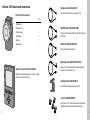
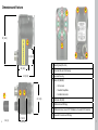
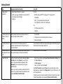
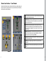
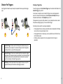
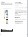
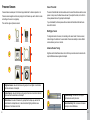
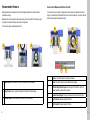
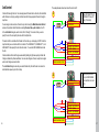
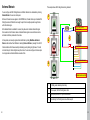
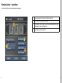
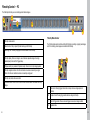
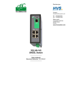
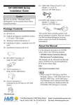
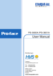
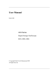
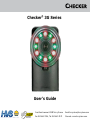
Checker® 3G Series
User’s Guide
System
DISTRIBUTEUR CONSEIL DEPUIS 1985
2 rue René Laennec 51500 Taissy France
Fax: 03 26 85 19 08, Tel : 03 26 82 49 29
Email: [email protected]
Site web : www.hvssystem.com
What is Checker 3G and what does it do?
Table of Contents
Checker 3G is a programmable vision
sensor that verifies the presence and
appearance of objects.
COGNEX
You configure Checker 3G by creating
one or more Jobs using a SensorView
Teach Pendant or a PC connected to
the Checker 3G’s USB port.
Checker’s One-Click™ sensors let
you check the presence, absence,
appearance, and size of part features
with a single click
OR
+ 24 VDC −
Once configured, Checker 3G is placed in Run Mode. In
Run mode Checker 3G automatically detects and inspects
parts, drawing power from and communicating with your other
automation devices through its built-in power and I/O connector.
COGNEX
+ 24 VDC −
You can connect a SensorView Teach Pendant
or a PC to a running Checker 3G at any time to
view part images, review statistics, or control
the operation of Checker 3G
OR
+ 24 VDC −
Checker 3G Products and Accessories . . . . . . . . . . . . . . . . . . . 4
Dimensions and Features . . . . . . . . . . . . . . . . . . . . . . . . . . 6
Getting Started . . . . . . . . . . . . . . . . . . . . . . . . . . . . . . . . 8
Verify Checker is Working -- Teach Pendant . . . . . . . . . . . . . . . . 10
Verify Checker is Working -- PC . . . . . . . . . . . . . . . . . . . . . . . 11
Checker User Interface -- Teach Pendant . . . . . . . . . . . . . . . . . . 12
Checker User Interface -- PC . . . . . . . . . . . . . . . . . . . . . . . . 14
Checker Part Triggers . . . . . . . . . . . . . . . . . . . . . . . . . . . . 16
Part Finding Sensor . . . . . . . . . . . . . . . . . . . . . . . . . . . . . 18
Presence Sensors . . . . . . . . . . . . . . . . . . . . . . . . . . . . . 20
Measurement Sensors . . . . . . . . . . . . . . . . . . . . . . . . . . . 22
Advanced Measurement Sensor Features . . . . . . . . . . . . . . . . . 24
Job Control . . . . . . . . . . . . . . . . . . . . . . . . . . . . . . . . . 26
External Retrain . . . . . . . . . . . . . . . . . . . . . . . . . . . . . . . 28
Run Time Display . . . . . . . . . . . . . . . . . . . . . . . . . . . . . . 30
Run Time Recording . . . . . . . . . . . . . . . . . . . . . . . . . . . . 31
Filmstrip Control -- SensorView . . . . . . . . . . . . . . . . . . . . . . . 32
Filmstrip Control -- PC . . . . . . . . . . . . . . . . . . . . . . . . . . . 34
Input/Output Wiring . . . . . . . . . . . . . . . . . . . . . . . . . . . . . 36
Circuit Diagrams (Typical) . . . . . . . . . . . . . . . . . . . . . . . . . . 37
Input/Output Wiring Examples . . . . . . . . . . . . . . . . . . . . . . . . 38
Working Distance and Field of View . . . . . . . . . . . . . . . . . . . . 40
Adjusting Focus . . . . . . . . . . . . . . . . . . . . . . . . . . . . . . . 41
Changing Lenses . . . . . . . . . . . . . . . . . . . . . . . . . . . . . . 42
Mounting Checker . . . . . . . . . . . . . . . . . . . . . . . . . . . . . . 44
Specifications . . . . . . . . . . . . . . . . . . . . . . . . . . . . . . . . 46
Precautions . . . . . . . . . . . . . . . . . . . . . . . . . . . . . . . . . 47
Checker 3G Products and Accessories
Flying Lead Cable (C3G-CBL-001)
Connects Checker directly to your equipment (5m).
Checker 3G Series Systems
3G1
Part Detection
√
Trigger Input Line
√
M12 USB Cable (CKR-200-CBL-USB)
Discrete Outputs
2
Personalities
2
Provides an IP67-compliant USB connection from Checker to
the PC (5m).
Presence
√
Measurement
√
I/O Extender (CKR-200-CBL-EXT)
Power and I/O extension cable (5m).
+ 24 VDC −
Right-Angle Cable (CKR-200-CBL-RT-003)
COGNEX
SensorView Teach Pendant (SV-350-001)
Standalone control panel that lets you configure, manage,
and monitor a Checker 3G sensor.
Power and I/O extension cable with low-profile right-angle
connector for Checker sensor (1m).
Mounting Bracket (CKR-200-BKT)
Provides flexible mounting options for Checker.
Lens Kit (CKR-200-LENSKIT)
Set of 3.6mm, 8mm, 16mm, and 25mm lenses that provide
expanded field of view and working distance options.
4
5
Dimensions and Features
4
3
67 (2.64)
67 (2.64)
2
2
22 (0.87)
22 (0.87)
6
39 (1.54)
39 (1.54)
60 (2.36)
60 (2.36)
7
6
mm (in)
mm (in)
1
1
Mounting holes (M4 x 4 mm)
2
Focus lock (M3, use 2.5 mm hex key)
3
Lens cover/focus ring
4
Status LED (GREEN):
1
41 (1.61)
41 (1.61)
27.5+0.5
27.5+0.5
(1.08+0.02)
(1.08+0.02)
5
•
On: Run mode
•
Slow blink: Setup Mode
•
Fast blink: Internal error
8
5
Part detect LED (RED)
6
USB connector with M12 plug
7
USB connector cover (cover or IP67 USB cable must be used for IP67 protection)
8
Power and I/O connector with M12 plug
7
Getting Started
Step
Using SensorView Teach Pendant
Using a PC
1: Review system
requirements
•
•
A PC with:
•
SensorView Teach Pendant v 2.4 or newer
24 VDC power supply, 525 mA (250 mA for Checker 3G, 275
mA for SensorView Teach Pendant)
USB cable
• Microsoft® Windows® 2000™ SP4, Windows XP™, or Windows Vista™
• 128 MB RAM
• USB 1.1 (2.0 recommended for best performance)
• 1024 x 768 (96 DPI) or 1280 x 1024 (120 DPI) display
and
•
•
2. Install SensorView Teach
Pendant or Checker PC
software
Install SensorView Teach Pendant by following instructions in
SensorView Teach Pendant User Manual.
1. Insert CD-ROM.
3. Connect Checker 3G to
power
Connect Checker 3G to 24 VDC power supply and I/O
equipment, as described on page 36. Verify that Checker 3G’s
illumination LEDs are lit.
Connect Checker 3G to 24 VDC power supply and I/O equipment, as described on page 36.
Verify that Checker 3G’s illumination LEDs are lit.
4. Connect Checker 3G to
SensorView Teach Pendant
or PC
Connect Checker 3G to SensorView Teach Pendant using USB
cable (use either USB port on SensorView Teach Pendant).
Connect Checker 3G to PC using USB cable.
5. Select Personality
Verify that SensorView Teach Pendant is displaying the Select
Personality screen. Select Presence if you are using this
sensor to check presence/absence or appearance. Select
Measurement if you are using this sensor to verify part or
feature dimensions.
•
2. If installer does not start automatically, double-click setup.exe.
3. Follow installer prompts.
Checker only prompts you to select its personality the first time it
is started. You can change Checker 3G’s personality at any time
by selecting Main Menu ►Select Personality.
8
24 VDC power supply, 250 mA
USB cable
Start the Checker software (select Cognex‑>Checker Vision Sensors‑>Checker from
the Windows Start menu).
• Click Get Connected.
• Select your Checker 3G and click Connect.
In the Select Personality screen select Presence if you are using this sensor to check
presence/absence or appearance. Select Measurement if you are using this sensor to verify
part or feature dimensions.
Checker only prompts you to select its personality the first time it is started. You can change
Checker 3G’s personality at any time by selecting Checker->Select Personality...
9
Verify Checker is Working -- Teach Pendant
COGNEX
Verify Checker is Working -- PC
SensorView should display the
Setup mode home screen, as
shown here.
The PC software should automatically connect to Checker 3G and display an image.
10
11
Checker User Interface -- Teach Pendant
SensorView Teach Pendant provides an interactive interface that lets you configure, manage, and
monitor a Checker 3G. For general information on how to use this interface, see the SensorView
Teach Pendant Users Guide and Reference.
6
COGNEX
1
Setup mode home screen. Each of the four steps at the left includes substeps to let
you create and modify Checker 3G jobs.
2
Navigation keys. Use these keys to select which item is active on the Checker 3G
screen. If a full-screen view is shown, the navigation keys let you select individual
items or controls on the screen.
3
Select softkey. Pressing this key activates or selects whatever item has been
selected using the navigation keys. If there are outstanding changes to an object,
this key’s name changes to Apply. If Checker is asking for input, this key’s name
changes to Yes.
4
Main Menu or Back softkey. In most contexts, this key returns to the previous
screen. If you are at a top-level screen, it opens the Main Menu. If Checker is
asking for input, this key’s name changes to Cancel.
5
Help softkey. Press this key for context-specific help. If Checker is asking for input,
this key’s name changes to No.
6
Run Mode screen. Displays images or statistics for a running Checker 3G or
Checker 200.
7
Main menu screen. Provides access to system settings, lets you connect to other
devices.
1
3
4
2
12
5
7
13
Checker User Interface -- PC
The Checker User Interface is PC software that lets you control Checker. You use this program
to view Checker images, create and modify Checker Jobs, and to monitor running Checkers.
1
1
Menu bar and status pane. The menu bar lets you open and save jobs and
manage Checker personalities and system settings. The status pane shows which
Checker is connected, the Job name and if it has been saved, along with results for
the most recent image.
2
Checker steps. Click each button in turn to build a Checker application.
3
Image display. Shows live video from Checker or individual images from a Filmstrip.
4
For each Checker step, instructions about what to do next are displayed here.
5
Control pane. The controls and information for each Checker step are displayed
here.
6
Filmstrip recording controls: Video, Snapshot, External Trigger, and Playback mode.
7
Filmstrip playback controls (only enabled in Playback mode). Lets you load and
display images recorded earlier or on another Checker.
8
Questions and answers related to the current step.
3
2
8
5
4
6
14
7
15
Checker Part Triggers
Choosing a Trigger Type
A part trigger tells Checker that a part is ready to be inspected. Checker supports three trigger
types.
You set the trigger type in the Start ►Select Trigger step on SensorView Teach Pendant or the
Select Part Trigger step on the PC.
In most cases, it is simplest to use the Internal Part Trigger, since no external equipment is
required. You create a Part Finding Sensor in the Set Up Sensors ►Find My Part step on
SensorView Teach Pendant or the Find My Part step on the PC.
If the appearance of your parts is highly variable, or if your line already has a device or sensor
that produces a part trigger signal, you can use an External Trigger.
APEX
APEX
APEX
Free Running mode is useful for several types of applications:
APEX
•
1
2
3
•
•
16
1
Internal Part Trigger: Checker uses its Part Finding Sensor to detect when a part is
present and ready to be inspected. You create and configure the Part Finding Sensor
by selecting a feature on your part that is always present.
2
External Part Trigger: Checker uses an external signal that your equipment supplies
to detect when a part is present and ready to be inspected. You use an External Trigger
by configuring a device such as a photoelectric sensor, contact switch, or proximity
sensor, then connecting it to Checker’s Trigger input line.
3
Free Running: Checker inspects each and every image that it acquires, not just the
images that contain a part or for which an external trigger is received.
Checking objects that move continuously and which cannot be detected with a Part Finding
sensor, such as a moving web of paper or metal.
Checking parts that move in multiple ways, such as a part that moves into the field of view
and then rotates in place.
Performing continuous inspection of non-moving objects to check for changes in
appearance.
17
Part Finding Sensor
Part Finding Sensors and Trigger Types
A Part Finding Sensor detects and locates your part in the image. You create a Part Finding
Sensor by drawing a box around a feature of part that is present on both good and bad parts.
Part Finding Sensors are used differently for different trigger types.
1
2
•
With an Internal Trigger, a Part Finding Sensor is required. The Part Finding Sensor tells
Checker that a part is present.
• With an External Trigger, a Part Finding Sensor is optional. If you do not use a Part Finding
Sensor, then the presence or measurement sensors will run in fixed positions. If you use
a Part Finding Sensor, then both the Part Finding Sensor and the External Trigger must
indicate a part before Checker will check it.
• In Free Running mode, a Part Finding Sensor is optional. If you do not use a Part Finding
Sensor, then the presence or measurement sensors will run in fixed positions. If you use
a Part Finding Sensor, then the Part Finding Sensor must detect a part in an image before
Checker will check it.
In all cases, if a Part Finding Sensor is used, then Checker uses the part’s detected location to
position the presence or measurement sensors.
Modifying a Part Finding Sensor
You can change the location where Checker looks for the part by simply moving the Part
Finding Sensor search region.
To change what a Part Finding Sensor looks for, you must either
•
•
18
1
The feature Checker is looking for.
2
The Search Region (where Checker looks for the feature).
Create a new Part Finding Sensor in Setup mode.
Use the External Retrain feature in Setup mode or Run mode.
19
Presence Sensors
Sensor Threshold
Presence Sensors evaluate part of a Checker image to determine if a feature is present or not.
The sensor threshold slider sets the level below which a sensor fails and above which a sensor
passes. In many cases, the default value works well. If you adjust the slider, set it so that it is
mid-way between the level for good parts and bad parts.
Presence sensors support one-click setup; simply click on the feature you want to check to create
and configure the sensor in a single step.
There are three types of presence sensors:
If you check Invert, the Sensor passes with levels below the threshold and fails with levels
above the threshold.
Modifying a Sensor
1
To change the location of a sensor, click and drag on the sensor border. To resize a sensor,
click and drag on the handle on the sensor border. Checker automatically re-trains a Pattern
sensor whenever you move or resize it.
Advanced Sensor Tuning
2
Brightness and Contrast Sensors have controls that let you tune the sensors to maximize the
reported difference between good and bad parts.
3
20
1
Brightness Sensor: Use when the feature of a good part is much lighter or much darker
than the same feature of a bad part.
2
Contrast Sensor: Use when the feature of a good part has more or less distinct dark and
light areas than the same feature of a bad part.
3
Pattern Sensor: Use when the feature of a good part has the shape you want and the
same feature of a bad part does not, or when inconsistent lighting conditions cause
Brightness or Contrast sensors to fail.
1
2
1
Brightness Range: Two sliders set the range of
brightness levels used by the sensor.
2
Contrast Sensitivity: Slider increases or decreases
sensitivity to contrast differences.
21
Measurement Sensors
How to use the Measurement Sensor Controls
Measurement Sensors evaluate part of a Checker image to determine if a feature is within a
specified size range.
In most cases, there is no need to change the one-click setup sensor. Features that are too
large or too small will fail, while features that are the correct size will pass. You use the controls
shown below to adjust a measurement sensor.
Measurement sensors support one-click setup; simply click on the center of the feature you want
to measure to create and configure the sensor in a single step.
There are three types of measurement sensors:
1
2
1
2
3
1
2
2
3
22
Width Sensor: Use to measure the width of a feature with vertical edges.
2
Height Sensor: Use to measure the height of a feature with horizontal edges.
3
Diameter Sensor: Use to measure the diameter of a circular feature
2
4
5
1
4
6
1
Drag bar: Click and drag here to reposition the sensor.
2
Blades: Click and drag here to select different feature edges.
3
Width and Height Sensor Region: Set the region for the feature. Use this to
exclude features you don’t want to measure.
4
Diameter Sensor Region: Set the inner and outer limits of the search region.
5
Low Threshold: Features smaller than this fail.
6
High Threshold: Features larger than this fail.
23
Advanced Measurement Sensor Features
Selecting the Edge Search Rule
Normally, width and height sensors measure the edges that are closest to the caliper blades while
diameter sensors measure the strongest edges.
Adjusting Edge Sensitivity
The sensitivity control for measurement sensors controls how many edges the sensor
evaluates when measuring your feature. As you move the sensitivity slider, the sensor displays
the edges that it finds as yellow lines.
You can select a different rule for edge selection using the Search For rule.
Closest
The sensor uses the edges that are closest in spacing and
position to the edges that it found when you created the sensor (or
when you adjusted the sensor position).
Narrowest/Smallest
The sensor uses the edges that are the closest together (Width
and Height sensor) or smallest in diameter (Diameter sensor).
Widest/Largest
The sensor uses the edges that are furthest apart (Width and
Height sensor) or largest in diameter (Diameter sensor).
Strongest
The sensor uses the edges with the strongest contrast (the
greatest difference in brightness between the two sides of the
edge).
If a measurement sensor locks onto the wrong edges for some parts, you can select a different
Search For rule to force the sensor to measure the correct edges.
You can set a different Search For rule for each sensor in your job.
24
1
2
1
Sensitivity Slider: slide right to detect more edges, slide left to detect fewer edges.
2
Edge Display: Found edges shown in yellow, as long as slider is clicked.
XX
If you are unable to get a measurement sensor to lock onto the edge you want to
measure, try increasing the sensitivity. If the sensor locks onto the wrong edge, try
reducing the sensitivity.
25
Job Control
The example below shows how to load the Job in slot 5:
Checker 3G has eight Job slots. You can assign saved Checker Jobs to Job slots, then load them
while Checker is running by sending Job Select and Job Change signals to Checker through its
input lines.
1
You can assign a Job saved on a Checker to any Job slot using the Main Menu ►Job Control
screen on SensorView Teach Pendant or selecting Checker->Set up Job Control on the PC.
1
–
24 VDC +
24 VDC+ POWER IN (RED)
GROUND (BLACK)
–
Raise JOB SELECT 0 and
JOB SELECT 2 lines (101
binary = 5 decimal).
24 VDC +
In the Job Control dialog box, each Job slot, from 0 through 7, has a menu that you use to
specify the Job. You can specify the same Job for multiple slots.
To load a Job from a Job slot while Checker is in Run mode, you must apply +24 VDC to the four
input lines that you use to load a Job from a Job slot. The JOB SELECT 0, JOB SELECT 1, and
JOB SELECT 2 lines specify the 3-bit Job slot number. You use the JOB CHANGE line to load
the Job.
Checker indicates that a Job Change succeeded by flashing its lights twice quickly. A failed Job
Change is indicated by three slow flashes. You can also configure a Checker output line to signal
when a Job Change succeeds or fails.
JOB CHANGE (YELLOW)
JOB SELECT 0 (WHITE/YELLOW)
JOB SELECT 1 (BROWN)
JOB SELECT 2 (WHITE/BROWN)
INPUT COMMON (WHITE/VIOLET)
Checker sources current
The Job Control dialog box also lets you select the Boot Job (the Job Checker runs when it is
restarted after a power cycle in Run mode).
2
–
24 VDC +
2
–
24 VDC +
24 VDC+ POWER IN (RED)
GROUND (BLACK)
Apply a pulse (minimum
15 ms) to JOB CHANGE
line to load the Job in Job
Slot 5.
JOB CHANGE (YELLOW)
JOB SELECT 0 (WHITE/YELLOW)
JOB SELECT 1 (BROWN)
JOB SELECT 2 (WHITE/BROWN)
INPUT COMMON (WHITE/VIOLET)
Checker sources current
26
27
External Retrain
You can configure both Part Finding Sensors and Pattern Sensors to be retrainable by checking
External Retrain in the sensor control panel.
Whenever Checker receives a signal on the RETRAIN line, Checker retrains any retrainable Part
Finding Sensors and Pattern Sensors using the part of most recently acquired image that lies
within the retrain region.
This example shows Part Finding Sensor being retrained:
1
– 24 VDC +
When External Retrain is enabled for a sensor, the yellow corner markers indicate the region
that is used to retrain the Sensor when an External Retrain signal is received. Sensors can be
retrained in both Setup mode and in Run mode.
In Setup mode, can manually signal an External Retrain by clicking Main Menu ►External
Retrain on SensorView Teach Pendant or selecting Checker->Retrain or pressing F9 on the PC.
24 VDC+ POWER IN (RED)
GROUND (BLACK)
3
2
Checker indicates that it has successfully retrained by quickly blinking its lights twice. If it could
not retrain the part, it blinks its lights slowly three times. You can also configure a Checker output
line to signal when an External Retrain succeeds or fails.
RETRAIN (VIOLET)
INPUT COMMON (WHITE/VIOLET)
4
Checker sources current
28
1
Part finding sensor detects part normally.
2
With a new part, the Part Finding Sensor fails.
3
Apply a pulse (minimum 15 ms) on RETRAIN line.
4
After retraining, Part Finding Sensor now finds new part.
29
Run Time Display
Run Time Recording
Run Time Display lets you control what images, if any, are displayed by Checker in Run mode.
Run Time Recording lets Checker record and save specific images while it is running, even
when not connected to SensorView Teach Pendant or a PC. You can choose from among any
of the current Checker results.
You configure Run Time Display from the Main Menu ►Display and Record screen on
SensorView Teach Pendant or the Display and Record step on the PC.
The Display: menu lets you pick which images to display in Run mode. You can choose from
among any of the current Checker results, including those that you define with ladder logic. When
Checker sees an image that makes the result true, it displays it.
The Freeze On: menu lets you control when the display is frozen (no longer updated with new
images). Whenever Checker sees an image that makes the Freeze On: result true, Checker stops
updating the Run-Time Display until you click Live.
Checker indicates that the Run-Time Display is frozen in two ways:
• The Frozen button is highlighted.
• The display itself includes the words Display Frozen.
To restart live display, click on the Live button.
30
When Checker sees an image that makes the specified result true, it records it. The next time
you connect to Checker with SensorView, the images are saved to a filmstrip (which you can
save to a USB flash drive). When you connect to a PC and enter Setup mode, the images are
automatically copied to the Filmstrip.
Checker has space for about 150 saved images. If you select Most Recent in the Type: menu,
then when the image storage space is full, the oldest images are discarded when new images
arrive.
If you select Most Marginal, then the images which came closest to not making the selected
answer true are saved. For example, if you specify the All Pass answer, then the images with
the sensors that came closest to failing are saved.
31
Filmstrip Control -- SensorView
The Filmstrip Control lets you record and play back Checker images.
3
1
Image source selector: Controls source of images in Setup mode.
2
Click to add one or more images to the Filmstrip.
3
Filmstrip display. Click on an image to view it. Blue bars separate images of a single
detected part (in Internal Part Trigger mode).
4
Filmstrip clear, load, and save controls.
2
1
4
32
33
Filmstrip Control -- PC
The Filmstrip Control lets you record and play back Checker images.
1
2
5
3
6
4
7
34
1
Filmstrip mode selector
2
Record button. Click (or press F5) to add an image to the Filmstrip.
3
Recording rate. How many images per second are added to the Filmstrip.
4
Filmstrip display. Click on an image to view it. Blue bars separate images of a single
detected part (in Internal Part Trigger mode).
5
Playback button (only enabled in Playback mode). Press to start or stop image playback.
6
Filmstrip navigation buttons. Click the inner buttons to advance or rewind by a single
frame. Click the outer buttons to advance or rewind by a single part.
7
Filmstrip clear, load, and save controls.
8
Information button. Hover the cursor here to view information about the selected Filmstrip
image.
8
Filmstrip Mode Selector
The Filmstrip mode selector controls whether the Filmstrip is recording or playing back images,
and if it is recording, when images are recorded to the Filmstrip.
11
12
10
9
9
Video mode. Pressing trigger button starts or stops continuous image capture to
Filmstrip.
10
Snapshot mode. Pressing trigger button adds one image to Filmstrip.
11
External Trigger mode. When an external trigger is received, an image is added.
12
Playback mode.
35
Input/Output Wiring
Circuit Diagrams (Typical)
The leads in the flying lead cable (C3G-CBL-001) are color-coded to indicate which signal is
carried on which line. The corresponding pins on the M12 connector are provided as well.
Power
Lead Color
Signal
M12 Pin
RED
24 VDC +
7
BLACK
24 VDC –
8
VIOLET
RETRAIN
5
YELLOW
JOB CHANGE
1
WHITE/YELLOW
JOB SELECT 0
2
BROWN
JOB SELECT 1
3
WHITE/BROWN
JOB SELECT 2
4
ORANGE
TRIGGER
10
WHITE/VIOLET
INPUT COMMON
6
BLUE
OUTPUT 0
11
GREY
OUTPUT 1
12
GREEN
OUTPUT COMMON
9
24 VDC
6
7
12
9
4
11
3
10
1
2
Note: Pin numbers for male connector
on Checker 3G are shown.
When wiring Checker 3G, observe the following precautions:
•
•
•
•
36
24 VDC+ POWER IN (RED)
–
GROUND (BLACK)
Trigger (Checker sinks current)
5
8
+
Use a listed power supply with an output rated 24 VDC, at least 250 mA, and marked Class 2,
Limited Power Source (LPS). Any other voltage creates a risk of fire or shock and can damage
Checker.
Connect the cable or connector shield to earth ground.
Make sure that no voltage potential exists between the USB ground on the PC and the
Checker chassis ground.
To reduce the risk of damage or malfunction, route all cables and wires away from highvoltage power sources.
24 VDC
+
–
TRIGGER (ORANGE)
INPUT COMMON (WHITE/VIOLET)
Trigger (Checker sources current)
24 VDC
+
–
INPUT COMMON (WHITE/VIOLET)
TRIGGER (ORANGE)
Outputs (Checker sinks current)
OUTPUT 1 (GREY)
24 VDC
+
–
OUTPUT 0 (BLUE)
OUTPUT COMMON (GREEN)
Outputs (Checker sources current)
24 VDC
+
–
OUTPUT COMMON (GREEN)
OUTPUT 1 (GREY)
OUTPUT 0 (BLUE)
37
Input/Output Wiring Examples
+ 24 VDC −
Trigger from PLC (Checker sources current) and Ouput to PLC (Checker sinks current)
24 VDC+ POWER IN (RED)
GROUND (BLACK)
DC +
DC common
Sink
Source
TRIGGER (ORANGE)
INPUT COMMON (WHITE/VIOLET)
Photosensor trigger (Checker sources current)
+ 24 VDC −
DC OUT
DC IN
0
1
2
3
4
5
COM
0
1
2
3
4
5
COM
DC OIN
DC OUT
0
1
2
3
4
5
COM
0
1
2
3
4
5
COM
24 VDC+ POWER IN (RED)
GROUND (BLACK)
+ 24 VDC −
24 VDC+ POWER IN (RED)
GROUND (BLACK)
TRIGGER (ORANGE)
INPUT COMMON (WHITE VIOLET)
OUTPUT 0 (BLUE)
OUTPUT COMMON (GREEN)
+ 24 VDC −
24 VDC+ POWER IN (RED)
GROUND (BLACK)
DC +
DC common
Source
Sink
38 Photosensor trigger (Checker sinks current)
TRIGGER (ORANGE)
INPUT COMMON (WHITE/VIOLET)
Stack light (Checker sinks current)
OUTPUT 1 (GREY)
OUTPUT 0 (BLUE)
OUTPUT COMMON (GREEN)
39
Working Distance and Field of View
Adjusting Focus
The distance from Checker’s lens cover to your part is the working distance; the field of view is
what Checker can see at that distance. As the working distance increases, so does the size of the
field of view.
Adjust focus using the clear ring on Checker. Using the supplied 2.5 mm hex key, you can lock
the focus adjustment by tightening the focus lock.
These charts show the field of view provided by the standard 5.8mm lens at various working
distances, as well as the fields of view provided by the lenses included in the optional Checker
Lens Kit (CKR-200-LENSKIT).
3.6 mm
3.6 mm
9
8
1
5.8 mm
8 mm
16 mm
25 mm
Field of View (in)
7
6
2
1
Closer
2
More distant
3
Focus lock
3
5.8 mm
5
8 mm
4
3
2
16 mm
1
25 mm
50
1
2
3
4
5
6
7
8
9
The lens cover both seals the front of Checker and lets you adjust the lens focus.
10 11 12
Working Distance (in)
3.6 mm
40
3.6 mm
9
Field of View (cm)
8
30
7
5.8 mm
3.6 mm
8 mm
18
14
5.8 mm
8
6
4
10
20
30
40
8 mm
Working Distance (cm)
16 mm
50
Lens is threaded into Checker
housing.
5
Large O-ring seals lens cover to
Checker housing.
6
Small O-ring rotates lens when lens
cover is rotated.
8 mm
4
6
3
16
10
12
40
5.8 mm
5
20
10
4
6
4
16 mm
2
16 mm
25 mm
1
25 mm
1
2
3
4
5
6
7
8
9
5
10 11 12
41
Changing Lenses
1
To remove the Checker lens, follow the
steps listed below.
1
Screw lens into Checker at
least five full rotations.
1
Unscrew lens cover. Lens
is secured to lens cover by
small internal O-ring.
2
Make sure both outer and
inner O-rings are seated in
place on the lens cover.
2
When lens is fully released,
remove cover with lens in
place.
3
Firmly and evenly press the
lens cover onto Checker
until it snaps into place.
3
Remove lens from lens cover.
Take care not to lose O-ring
that secures lens to lens
cover.
1
2
Note: Failure to follow these
instructions can cause damage to your
Checker.
Note: Failure to follow these
instructions can cause damage to your
Checker.
2
3
42
To install the Checker lens, follow the
steps listed below.
4
x5
3
Screw in the lens cover to
bring Checker into focus.
4
43
Mounting Checker
XX
XX
The optional Checker mounting bracket lets you easily position and adjust Checker on your line.
Caution: Do not use a mounting screw with an exposed thread depth of greater
than 5mm. Allowing the mounting screw to bottom in the mounting hole can
damage Checker.
Caution: The maximum torque for a mounting screw is 1.8 nM (16 inch-pounds).
Exceeding this torque value can damage Checker.
Mounting Checker at a slight angle can reduce reflections from your part’s surfaces, improving
performance. Adjust the mounting angle to provide the clearest image of the part features you are
checking.
A
C
B
19 (0.75)
A
25.4 (1.0)
C
20 (0.787)
A
1/4-20 UNC
B
M6 x 1.0
C
∅ = 7.14 (0.281)
B
mm (in)
44
45
Specifications
Precautions
Cable
24AWG, 5 m, M12 connector (power and I/O)
Power requirements
Voltage: +24 VDC (22-26 VDC)
Current: 250 mA max
Discrete
Inputs
Input ON: > 10 VDC (> 6 mA)
Input OFF: < 2 VDC (< 1.5 mA)
Protection: Opto-isolated, polarity-independent
Discrete
Outputs
Output: Solid state switch
Rating: 100 mA, 24 VDC Max
Max voltage drop: 3.5 VDC @ 100 mA
Max load: 100 mA
Protection: Opto-isolated, protected from short circuit, overcurrent, and
reverse polarity.
24V power
fuse
500 mA, 60 V rated resetable fuse that will recover after an overload is removed. Protects against over voltage and reverse wiring.
Output fuse
200 mA, 30 V rated resetable fuse that will recover after an overload is removed. Protects each output from over current.
Weight
3.5 oz. (100g)
Environmental
limits
Operating temperature: 32° to 122°F (0° to 50°C)
Storage temperature: -22° to 176°F (-30° to 80°C)
Operating humidity: 0% - 90% non-condensing
Maximum operating altitude: 4000 meters
Protection: IP67
Pollution degree: 2
Shock
80Gs for 5ms on each axis (per IEC 68-2-2)
Vibration
10Gs (10-500Hz) at 100 M/sec2 / 15mm for 2 hours in each axis (per IEC 682-6)
Certification
RoHS
Observe these precautions when installing Checker to reduce the risk of injury or equipment
damage:
• Do not use Checker in applications where an incorrect or absent output signal
could cause human injury.
• Checker is intended for indoor use only.
• Do not attempt to adjust Checker’s focus when moving parts and/or equipment are present.
• Use a listed power supply with an output rated 24 VDC, at least 250 mA, and marked
Class 2, Limited Power Source (LPS). Any other voltage creates a risk of fire or shock and
can damage Checker.
• Connect the cable shield to earth ground.
• Make sure that no voltage potential exists between the USB ground on the PC and the
Checker chassis ground.
• An IP67-compliant plug or cable must be fitted to the USB connector for Checker to meet
the IP67 protection standard.
• Do not install Checker in locations that expose it to environmental hazards such as
excessive heat, humidity, impact, vibration, corrosive substances, flammable substances,
or static electricity.
• To reduce the risk of damage or malfunction, route all cables and wires away from highvoltage power sources.
• Do not extend I/O and power cables longer than 30 meters.
• Make sure that the mounting screws do not bottom in the mounting holes; using too long
a mounting screw can damage Checker.
• Do not attempt to modify Checker. Modifications will void the warranty.
NOTE: This equipment has been tested and found to comply with the limits for a Class A digital device, pursuant to Part 15 of the
FCC Rules. These limits are designed to provide reasonable protection against harmful interference when the equipment is operated
in a commercial environment. This equipment generates, uses, and can radiate radio frequency energy and, if not installed and used
in accordance with the instruction manual, may cause harmful interference to radio communications. Operation of this equipment in
a residential area is likely to cause harmful interference in which case the user will be required to correct the interference at his own
expense.
Copyright © 2009 Cognex Corporation All Rights Reserved. This document may not be copied in whole or in part, nor transferred
to any other media or language, without the written permission of Cognex Corporation. Cognex, the Cognex logo, Checker, and the
Checker logo are trademarks, or registered trademarks, of Cognex Corporation.
This product is covered by one or more of the following US patents and one or more pending US and foreign patents, which, when
issued are listed on the Cognex web site at http://www.cognex.com/patents.
5583954, 5602937, 5964844, 6215915, 6381375, 6421458, 6931602, 7305114, and 7417803
46
47
System
DISTRIBUTEUR CONSEIL DEPUIS 1985
2 rue René Laennec 51500 Taissy France
Fax: 03 26 85 19 08, Tel : 03 26 82 49 29
590-7096
Email: [email protected]
Site web : www.hvssystem.com