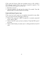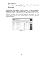
1
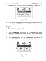
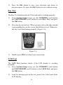
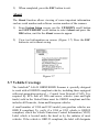
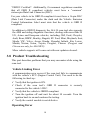
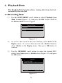
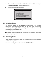
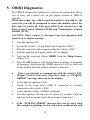
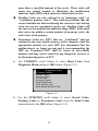
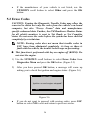
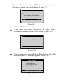
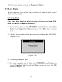
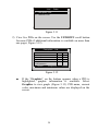
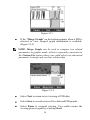
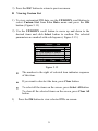
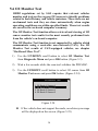
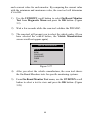
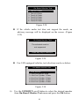
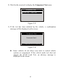
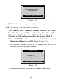
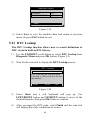
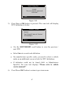
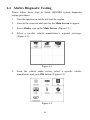
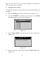
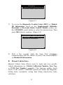
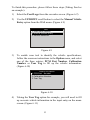
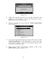
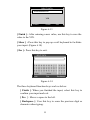
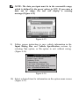
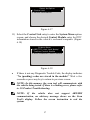
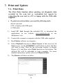
Table of Contents 1. 2. 3. 4. 5. 6. 7. 8. SAFETY PRECAUTIONS AND WARNINGS .............................................. 1 GENERAL INFORMATION .......................................................................... 2 2.1 ON-BOARD DIAGNOSTICS (OBD) II ............................................................. 2 2.2 DIAGNOSTIC TROUBLE CODES (DTCS) ........................................................ 2 2.3 LOCATION OF THE DATA LINK CONNECTOR (DLC) .................................... 3 2.4 OBD II READINESS MONITORS .................................................................... 4 2.5 OBD II MONITOR READINESS STATUS ......................................................... 5 2.6 OBD II DEFINITIONS .................................................................................... 6 2.7 OBD II MODES OF OPERATION .................................................................... 7 USING THE SCAN TOOL ............................................................................ 10 3.1 TOOL DESCRIPTION .................................................................................... 10 3.2 SPECIFICATIONS .......................................................................................... 11 3.3 ACCESSORIES INCLUDED............................................................................. 12 3.4 KEYBOARD .................................................................................................. 12 3.5 POWER ........................................................................................................ 12 3.6 SYSTEM SETUP ............................................................................................ 13 3.7 VEHICLE COVERAGE .................................................................................. 17 3.8 PRODUCT TROUBLESHOOTING.................................................................... 18 PLAYBACK DATA ....................................................................................... 20 4.1 REVIEWING DATA ....................................................................................... 20 4.2 DELETING DATA .......................................................................................... 21 4.3 PRINTING DATA ........................................................................................... 21 OBDII DIAGNOSTICS ................................................................................. 22 5.1 READ CODES ............................................................................................... 23 5.2 ERASING CODES .......................................................................................... 26 5.3 LIVE DATA .................................................................................................. 28 5.4 FREEZE FRAME ........................................................................................... 34 5.5 RETRIEVING I/M READINESS STATUS......................................................... 35 5.6 O2 MONITOR TEST ..................................................................................... 38 5.7 ON-BOARD MONITOR TEST ........................................................................ 39 5.8 COMPONENT TEST ...................................................................................... 42 5.9 VIEWING VEHICLE INFORMATION .............................................................. 44 5.10 MODULES PRESENT .................................................................................... 45 5.11 DTC LOOKUP ............................................................................................. 46 ABSSRS TESTING ........................................................................................ 48 6.1 ABSSRS DIAGNOSTIC TESTING ................................................................... 49 PRINT AND UPDATE................................................................................... 58 7.1 PRINT DATA ................................................................................................ 58 7.2 SOFTWARE UPDATE .................................................................................... 59 WARRANTY AND SERVICE ...................................................................... 65 8.1 LIMITED ONE YEAR WARRANTY ................................................................ 65 8.2 SERVICE PROCEDURES ................................................................................ 65 1. Safety Precautions and Warnings To prevent personal injury or damage to vehicles and/or the scan tool, read this instruction manual first and observe the following safety precautions at a minimum whenever working on a vehicle: Always perform automotive testing in a safe environment. Wear safety eye protection that meets ANSI standards. Keep clothing, hair, hands, tools, test equipment, etc. away from all moving or hot engine parts. Operate the vehicle in a well ventilated work area: Exhaust gases are poisonous. Put blocks in front of the drive wheels and never leave the vehicle unattended while running tests. Use extreme caution when working around the ignition coil, distributor cap, ignition wires and spark plugs. These components create hazardous voltages when the engine is running. Put the transmission in PARK (for automatic transmission) or NEUTRAL (for manual transmission) and make sure the parking brake is engaged. Keep a fire extinguisher suitable for gasoline/chemical/ electrical fires nearby. Don’t connect or disconnect any test equipment while the ignition is on or the engine is running. Keep the scan tool dry, clean, free from oil/water or grease. Use a mild detergent on a clean cloth to clean the outside of the scan tool, when necessary. 1 2. General Information 2.1 On-Board Diagnostics (OBD) II The first generation of On-Board Diagnostics (called OBD I) was developed by the California Air Resources Board (ARB) and implemented in 1988 to monitor some of the emission control components on vehicles. As technology evolved and the desire to improve the On-Board Diagnostic system increased, a new generation of On-Board Diagnostic system was developed. This second generation of On-Board Diagnostic regulations is called "OBD II". The OBD II system is designed to monitor emission control systems and key engine components by performing either continuous or periodic tests of specific components and vehicle conditions. When a problem is detected, the OBD II system turns on a warning lamp (MIL) on the vehicle instrument panel to alert the driver typically by the phrase of “Check Engine” or “Service Engine Soon”. The system will also store important information about the detected malfunction so that a technician can accurately find and fix the problem. Here below follow three pieces of such valuable information: 1) Whether the Malfunction Indicator Light (MIL) is commanded 'on' or 'off'; 2) Which, if any, Diagnostic Trouble Codes (DTCs) are stored; 3) Readiness Monitor status. 2.2 Diagnostic Trouble Codes (DTCs) OBD II Diagnostic Trouble Codes are codes that are stored by the on-board computer diagnostic system in response to a problem found in the vehicle. These codes identify a particular problem area and are intended to provide you with a guide as to where a fault might be occurring within a vehicle. OBD II Diagnostic Trouble Codes consists of a five-digit alphanumeric code. The first character, a letter, identifies which control system sets the code. The other four characters, all numbers, provide additional information on where the DTC originated and the operating conditions that caused it to set. Here below is an example to illustrate the structure of the digits: 2 2.3 Location of the Data Link Connector (DLC) The DLC (Data Link Connector or Diagnostic Link Connector) is the standardized 16-cavity connector where diagnostic scan tools interface with the vehicle's on-board computer. The DLC is usually located 12 inches from the center of the instrument panel (dash), under or around the driver’s side for most vehicles. If Data Link Connector is not located under dashboard, a label should be there telling location. For some Asian and European vehicles, the DLC is located behind the ashtray and the ashtray must be removed to access the connector. If the DLC cannot be found, refer to the vehicle’s service manual for the location. 3 2.4 OBD II Readiness Monitors An important part of a vehicle’s OBD II system is the Readiness Monitors, which are indicators used to find out if all of the emissions components have been evaluated by the OBD II system. They are running periodic tests on specific systems and components to ensure that they are performing within allowable limits. Currently, there are eleven OBD II Readiness Monitors (or I/M Monitors) defined by the U.S. Environmental Protection Agency (EPA). Not all monitors are supported by all vehicles and the exact number of monitors in any vehicle depends on the motor vehicle manufacturer’s emissions control strategy. Continuous Monitors -- Some of the vehicle components or systems are continuously tested by the vehicle’s OBD II system, while others are tested only under specific vehicle operating conditions. The continuously monitored components listed below are always ready: 1)Misfire 2)Fuel System 3)Comprehensive Components (CCM) Once the vehicle is running, the OBD II system is continuously checking the above components, monitoring key engine sensors, watching for engine misfire, and monitoring fuel demands. Non-Continuous Monitors -- Unlike the continuous monitors, many emissions and engine system components require the vehicle to be operated under specific conditions before the monitor is ready. These monitors are termed non-continuous monitors. For different ignition type engines, the available monitors are different too. 4 The following monitors are to be used for spark ignition engines only: 1) 2) 3) 4) 5) 6) 7) EGR System O2 Sensors Catalyst Evaporative System O2 Sensor Heater Secondary air Heated Catalyst The following monitors are to be used for compression ignition engines only: 1) 2) 3) 4) 5) 6) EGR System NMHC Catalyst NOx aftertreatment Boost pressure system Exhaust gas sensor PM filter 2.5 OBD II Monitor Readiness Status OBD II systems must indicate whether or not the vehicle’s PCM’s monitor system has completed testing on each component. Components that have been tested will be reported as “Ready”, or “Complete”, meaning they have been tested by the OBD II system. The purpose of recording readiness status is to allow inspectors to determine if the vehicle’s OBD II system has tested all the components and/or systems. The power-train control module (PCM) sets a monitor to “Ready” or “Complete” after an appropriate drive cycle has been performed. The drive cycle that enables a monitor and sets readiness codes to “Ready” varies for each individual monitor. Once a monitor is set as “Ready” or “Complete”, it will remain in this state. A number of factors, including erasing of diagnostic trouble codes (DTCs) with a scan tool or a disconnected battery, can result in Readiness Monitors being set 5 to “Not Ready”. Since the three continuous monitors are constantly evaluating, they will be reported as “Ready” all of the time. If testing of a particular supported non-continuous monitor has not been completed, the monitor status will be reported as “Not Complete” or “Not Ready.” In order for the OBD monitor system to become ready, the vehicle should be driven under a variety of normal operating conditions. These operating conditions may include a mix of highway driving and stop and go, city type driving, and at least one overnight-off period. For specific information on getting your vehicle’s OBD monitor system ready, please consult your vehicle owner’s manual. 2.6 OBD II Definitions Power-train Control Module (PCM) -- OBD II terminology for the on-board computer that controls engine and drive train. Malfunction Indicator Light (MIL) -- Malfunction Indicator Light (Service Engine Soon, Check Engine) is a term used for the light on the instrument panel. It is to alert the driver and/or the repair technician that there is a problem with one or more of vehicle's systems and may cause emissions to exceed federal standards. If the MIL illuminates with a steady light, it indicates that a problem has been detected and the vehicle should be serviced as soon as possible. Under certain conditions, the dashboard light will blink or flash. This indicates a severe problem and flashing is intended to discourage vehicle operation. The vehicle onboard diagnostic system cannot turn the MIL off until necessary repairs are completed or the condition no longer exists. DTC -- Diagnostic Trouble Codes (DTC) that identify which section of the emission control system has malfunctioned. Enabling Criteria -- Also termed Enabling Conditions. They are the vehicle-specific events or conditions that must occur within the engine before the various monitors will set, or run. Some monitors require the vehicle to follow a prescribed “drive cycle” routine as part of the enabling criteria. Drive cycles vary among vehicles and for each monitor in any particular vehicle. 6 OBD II Drive Cycle -- A specific mode of vehicle operation that provides conditions required to set all the readiness monitors applicable to the vehicle to the “ready” condition. The purpose of completing an OBD II drive cycle is to force the vehicle to run its onboard diagnostics. Some form of a drive cycle needs to be performed after DTCs have been erased from the PCM’s memory or after the battery has been disconnected. Running through a vehicle’s complete drive cycle will “set” the readiness monitors so that future faults can be detected. Drive cycles vary depending on the vehicle and the monitor that needs to be reset. For vehicle specific drive cycle, consult the vehicle’s Owner’s Manual. Freeze Frame Data -- When an emissions related fault occurs, the OBD II system not only sets a code but also records a snapshot of the vehicle operating parameters to help in identifying the problem. This set of values is referred to as Freeze Frame Data and may include important engine parameters such as engine RPM, vehicle speed, air flow, engine load, fuel pressure, fuel trim value, engine coolant temperature, ignition timing advance, or closed loop status. 2.7 OBD II Modes of Operation Here is a basic introduction to the OBD II communication protocol. Mode byte: The first byte in the stream is the mode number. There are 10 modes for diagnostic requests. The first byte in the response data bytes is this same number plus 64. For example, a mode 1 request would have the first data byte = 1, and the response would have the first data byte = 65. Here is a brief description of the modes: Mode $01 – Identifies the Power-train information and shows current data available to the scan tool. This data includes: DTC set, status of on-board tests, and vehicle data such as engine RPM, temperatures, ignition advance, speed, air flow rates, and closed loop status for fuel system. Mode $02 – Displays Freeze Frame data. Same data as in mode 1, but it was captured and stored when a malfunction occurred and a DTC was set. Some of the PIDs for mode one are not implemented in this mode. 7 Mode $03 – Displays the type of power-train or emission related DTCs stored by a 5 digit code identifying the faults. There may be more than one response message if there are more trouble codes than will fit in the data bytes of the response message, or if there are more than one ECU computer responding. Mode $04 – Used to clear DTCs and Freeze Frame data. This clears all diagnostic trouble codes that may be set including freeze frame data and readiness monitors. Mode $05 – Oxygen Sensor Test Results. This mode displays the oxygen sensor monitor screen and the test results gathered about the oxygen sensor. There are ten numbers available for diagnostics: 1. 2. 3. 4. 5. 6. 7. 8. 9. $01 Rich-to-Lean O2 sensor threshold voltage. $02 Lean-to-Rich O2 sensor threshold voltage. $03 Low sensor voltage threshold for switch time measurement. $04 High sensor voltage threshold for switch time measurement. $05 Rich-to-Lean switch time in ms. $06 Lean-to-Rich switch time in ms. $07 Minimum voltage for test. $08 Maximum voltage for test. $09 Time between voltage transitions in ms. Mode $06 – Non-continuously Monitored Systems test results. There are typically a minimum value, a maximum value, and a current value for each non-continuous monitor. This data is optional, and it is defined by a given vehicle maker if it’s used. Mode $07 – Request for DTCs (pending) from Continuously Monitored Systems after a single driving cycle has been performed to determine if repair has fixed a problem. This used by service technicians to verify repair was performed properly and after clearing diagnostic trouble codes. 8 Mode $08 – This special Control Mode requests control of the on-board system, test, or component bi-directionally (where applicable). This mode is manufacturer specific. Mode $09 – Reports vehicle information. This information includes vehicle VIN number and calibration information stored in the vehicle ECUs. Mode $0A – Request Emission-Related Diagnostic Trouble Codes with Permanent Status. This mode is required for all emissions-related DTCs. The presence of permanent DTCs at an inspection without the MIL illuminated is an indication that a proper repair was not verified by the on-board monitoring system. 9 3. Using the Scan Tool 3.1 Tool Description 1) 2) OBD II CONNECTOR – Connects the scan tool to the vehicle’s Data Link Connector (DLC). LCD DISPLAY – Indicates test results. 3) FUNCTION BUTTONS – Corresponds with “buttons” on screen for executing commands. 4) ESC BUTTON – Cancels a selection (or action) from a menu or returns to the previous screen. 10 5) LEFT SCROLL BUTTON – When look up DTC definitions, moves to previous character and views additional information on previous screens if DTC definition covers more than one screen; views previous screen or previous frames of recorded data. It is also used to view previous trouble code when viewing DTCs. 6) HELP BUTTON – Provides help information and Code Breaker function. 7) DOWN SCROLL BUTTON –Moves down through menu and submenu items in menu mode. When more than one screen of data is retrieved, moves down through the current screen to next screens for additional data. When looking up DTC, it is used to change value of selected character. 8) RIGHT SCROLL BUTTON – When look up DTC definitions, moves to next character and view additional information on next screens if DTC definition covers more than one screen; views next screen or next frames of recorded data. It is also used to view next trouble code when viewing DTCs. 9) OK BUTTON – Confirms a selection (or action) from a menu. UP SCROLL BUTTON – Moves up through menu and submenu items in menu mode. When more than one screen of data is retrieved, moves up through the current screen to the previous screens for additional data. When looking up DTC, it is used to change value of selected character. 11) USB CONNECTOR – Connects the scan tool to the PC for printing. 10) 12) TF CARD SLOT – Holds the TF card. 3.2 Specifications 1) 2) Display: TFT color display (320 x 240 dpi) Operating Temperature: 0 to 60°C (32 to 140 F°) 11 3) 4) 5) 6) Storage Temperature: -20 to 70°C (-4 to 158 F°) External Power: 8.0 to 18.0 V power provided via vehicle battery Dimensions: Length Width Height 199 mm (7.83”) 104.5 mm (4.11”) 37.5 mm (1.48”) Weight: 0.28kg(without wire) 0.484kg(with wire) 3.3 Accessories Included 1) 2) 3) 4) 5) 6) User’s Manual -- Instructions on tool operations. CD -- Includes user’s manual, MaxiLink update software, and etc. OBDII cable -- Provides power to tool and communicates between tool and vehicle. USB cable -- Used to print retrieved data. Protective Nylon Case – A nylon case to store the tool when not in use. TF card -- Used to store data and to upgrade the scan tool 3.4 Keyboard No solvents such as alcohol are allowed to clean the keypad or display. Use a mild nonabrasive detergent and a soft cotton cloth. Do not soak the keypad as the keypad is not waterproof. 3.5 Power The scan tool is powered via the vehicle Data Link Connector (DLC). Just follow the steps below to turn on the scan tool: 1) Connect the OBD II Cable to scan tool. 2) Find DLC on vehicle. A plastic DLC cover may be found for some vehicles and you need to remove it before plugging the OBDII cable. 3) Plug OBD II cable to the vehicle’s DLC. 12 4) Power up the scan tool , and wait for the Main Screen to appear.(Figure 3.1) Figure 3.1 3.6 System Setup The System Setup functions allow you to adjust default settings and view information about the scan tool. 1) Language: Selects the desired language. 2) Unit of measure: Sets the unit of measure to English or Metric. 3) Beep Set: Turns on/off beep. 4) Key Test: Checks if the keyboard is working properly. 5) LCD Test: Checks if the LCD display is working properly. 6) About: Provides information of the scan tool. Settings of the unit will remain until change to the existing settings is made. To enter the Setup menu From the Main Screen: Use LEFT/RIGHT scroll button to select Setup, and press the OK button. Following the instructions to do adjustments and settings could make your diagnosis more conveniently and easily. (Figure 3.2) 13 Figure 3.2 Language Setup English is the default language. 1) From System Setup screen, use the UP/DOWN scroll button and LEFT/RIGHT scroll button to select Language, and press the OK button. 2) Use the UP/DOWN scroll button to select the desired language and press the OK button to save your selection and return to previous screen. (Figure 3.3) Figure 3.3 Unit of Measure Metric is the default measurement unit. 1) From System Setup screen, use the LEFT/RIGHT scroll button to select EN/METRIC and press the OK button. 14 2) From Unit of Measure screen, use the LEFT/RIGHT scroll button to select the desired unit of measurement. (Figure 3.4 ) Figure 3.4 3) Press the OK button to save your selection and return to previous menu. Or, press the ESC button to exit without saving. Beep Set The default setting is Beep On. 1) From System Setup screen, use the UP/DOWN scroll button and LEFT/RIGHT scroll button to select Beep and press the OK button. 2) From Beep Set menu, use the LEFT/RIGHT scroll button to select ON or OFF to turn on/off the beep. (Figure 3.5) Figure 3.5 15 3) Press the OK button to save your selection and return to previous menu. Or, press the ESC button to exit without saving. Key Test The Key Test function checks if the keyboard is working properly. 1) From System Setup screen, use the UP/DOWN scroll button and LEFT/RIGHT scroll button to select Key Test, and press the OK button. 2) Press any key to start test. When you press a key, the edge around corresponding key on the screen should turn to red. Otherwise, the key is not functioning properly. (Figure 3.6) Figure 3.6 3) Double press ESC to return to previous menu. LCD Test The LCD Test function checks if the LCD display is working normally. 1) From System Setup screen, use the UP/DOWN scroll button and LEFT/RIGHT scroll button to select LCD Test, and press the OK button. 2) Look for missing spots in the red, green, blue, black and white LCD display. 16 3) When completed, press the ESC button to exit. About The About function allows viewing of some important information such as serial number and software version number of the scanner. 1) From System Setup screen, use the UP/DOWN scroll button and LEFT/RIGHT scroll button to select About and press the OK button, wait for the About screen to appear. 2) View tool information on screen. (Figure 3.7) Press the ESC button to exit without saving. Figure 3.7 3.7 Vehicle Coverage The AutoLink AL619 OBDII/EOBD Scanner is specially designed to work with all OBD II compliant vehicles, including those equipped with next-generation protocol -- Control Area Network (CAN). It is required by EPA that all 1996 and newer vehicles (cars and light trucks) sold in the United States must be OBD II compliant and this includes all Domestic, Asian and European vehicles. A small number of 1994 and 1995 model year gasoline vehicles are OBD II compliant. To verify if a 1994 or 1995 vehicle is OBD II compliant, check the Vehicle Emissions Control Information (VECI) Label which is located under the hood or by the radiator of most vehicles. If the vehicle is OBD II compliant, the label will designate 17 “OBD II Certified”. Additionally, Government regulations mandate that all OBD II compliant vehicles must have a “common” sixteen-pin Data Link Connector (DLC). For your vehicle to be OBD II compliant it must have a 16-pin DLC (Data Link Connector) under the dash and the Vehicle Emission Control Information Label must state that the vehicle is OBD II compliant. In addition to OBD II diagnosis, the AL619 scan tool also supports the ABS and airbag diagnostic functions, dealing with more than 20 US, Asian and European vehicles, including GM, Ford, Chrysler, Audi, Benz, BMW, Bentley, Bugatti, EU Ford, Mini, Maybach, Seat, Skoda, VW, Volvo, Acura, Honda, Hyundai, Infiniti, Kia, Lexus, Mazda, Nissan, Scion, Toyota, Peugeot, Citroen. (Peugeot and Citroen are only for AL619EU). More vehicle supports will come out with new updates released. 3.8 Product Troubleshooting This part describes problems that you may encounter while using the scan tool. Vehicle Linking Error A communication error occurs if the scan tool fails to communicate with the vehicle’s ECU (Engine Control Unit). You need to do the following to check up: Verify that the ignition is ON. Check if the scan tool’s OBD II connector is securely connected to the vehicle’s DLC. Verify that the vehicle is OBDII compliant. Turn the ignition off and wait for about 10 seconds. Turn the ignition back to on and continue the testing. Verify the control module is not defective. Operating Error 18 If the scan tool freezes, then an exception occurs or the vehicle’s ECU (Engine Control Unit) is too slow to respond to requests. You need to do the following to reset the tool: Reset the scan tool. Turn the ignition off and wait for about 10 seconds. Turn the ignition back to on and continue the testing. Scan tool doesn’t power up If the scan tool won’t power up or operates incorrectly in any other way, you need to do the following to check up: Check if the scan tool’s OBD II connector is securely connected to the vehicle’s DLC; Check if the DLC pins are bent or broken. Clean the DLC pins if necessary. Check vehicle battery to make sure it is still good with at least 8.0 volts. 19 4. Playback Data The Playback Data function allows viewing data from last test recorded by the scan tool. 4.1 Reviewing Data 1) Use the LEFT/RIGHT scroll button to select Playback from Main Screen (Figure 3.1), and press the OK button. Wait for the Review Data screen to appear. Review Data 1.AbsSrs 2.Scan Figure 4.1 2) To review data saved in the scan function, select Scan in the Replay menu. To review data saved in the AbsSrs function, select AbsSrs in the Replay menu. Then press OK button to continue. 3) Use the UP/DOWN scroll button to select the desired DTC entries from Scan menu or AbsSrs menu (Figure 4.2), and press the OK button. AbsSrs 1. Trouble Code /scan/ABSSRS/USA/GM/saved Delete Delete All Figure 4.2 20 If no data from previously tested vehicle is recorded, a message “No data available!” shows on the screen. Review selected data on screen. Vehicle Specification Vehicle: Mustang Engine Type: Other Capacity: 3.8L Transmission: Manual Fuel Type: Gasoline Emission Level: Federal Emission VIN:1FAFP40462F100819 PrefSuf:2R3APB VersionID:4612 Print Figure 4.3 4.2 Deleting Data By selecting Delete on the AbsSrs screen (Figure 4.2), you are allowed to erase the selected data on the scan tool. Review the recordings thoroughly before erasing. You could also erase all recordings by select Delete All. NOTE: Don’t use Delete All unless you are definitely sure what you are going to proceed. 4.3 Printing Data Print option allows you to print the recorded files to your computer and then to the printer. For more details, please refer to chapter 7.1 Print Data. 21 5. OBDII Diagnostics The OBD II Diagnostics function is a fast-access option that allows you to carry out a quick test on the engine system of OBD II vehicles. When more than one vehicle control module is detected by the scan tool, you will be prompted to select the module where the data may be retrieved. The most often to be selected are the Power-train Control Module [PCM] and Transmission Control Module [TCM]. CAUTION: Don’t connect or disconnect any test equipment with ignition on or engine running. 1) 2) 3) 4) 5) Turn the ignition off. Locate the vehicle’s 16-pin Data Link Connector (DLC). Plug the scan tool cable connector into the vehicle’s DLC. Turn the ignition on. Engine can be off or running. Turn on the scan tool. Select OBDII from the Main Screen. (Figure 3.1) 6) Press the OK button to wait for the Menu to appear. A sequence of messages displaying the OBDII protocols will be observed on the display until the vehicle protocol is detected. If the scan tool fails to communicate with the vehicle’s ECU (Engine Control Unit) more than three times, a “LINKING ERROR!” message shows up on the display. Verify that the ignition is ON. Check if the scan tool’s OBD II connector is securely connected to the vehicle’s DLC. Verify that the vehicle is OBD2 compliant. Turn the ignition off and wait for about 10 seconds. Turn the ignition back to on and repeat the procedure from step 5. If the “LINKING ERROR” message does not go away, then there might be problems for the scan tool to communicate with 22 the vehicle. Contact your local distributor or the manufacturer’s customer service department for assistance. 7) View a summary of system status (MIL status, DTC counts, Monitor status) on screen. (Figure 5.1 ) Press ESC button for Diagnostic Menu (Figure 5.3) to come up. System Status MIL Status Codes Found Monitors N/A Monitors OK Monitors INC OFF 0 8 2 0 Save OK Figure 5.1 If more than one module is detected, you will be prompted to select a module before testing. (Figure 5.2 ) Control Module Module $10 Module $A4 Figure 5.2 Use the UP/DOWN scroll button to select a module and press the OK button. 5.1 Read Codes Reading Codes can be done with the key on engine off (KOEO) or with the key on engine running (KOER). Stored Codes are also known as “hard codes”, which are fault codes, or trouble codes that have been stored in the vehicle computer memory because the faults have reoccurred for 23 more than a specified amount of key-cycles. These codes will cause the control module to illuminate the malfunction indicator light (MIL) when emission-related fault occurs. Pending Codes are also referred to as “maturing codes” or “continuous monitor codes”. They indicate problems that the control module has detected during the current or last driving cycle but are not considered serious yet. Pending Codes will not turn on the malfunction indicator lamp (MIL). If the fault does not occur within a certain number of warm-up cycles, the code clears from memory. Permanent Codes are DTCs that are "confirmed" and are retained in the non-volatile memory of the computer until the appropriate monitor for each DTC has determined that the malfunction is no longer present and is not commanding the MIL on. Permanent DTC shall be stored in non-volatile memory and may not be erased by any diagnostic services or by disconnecting power to ECU. 1) Use UP/DOWN scroll button to select Read Codes from Diagnostic Menu and press OK button. (Figure 5.3 ) Diagnostic Menu 1.System Status 2.Read Codes 3.Erase Codes 4.Live Data 5.Freeze Frame 6.I/M Readiness 7.O2 Monitor Test 8.On-Board Monitor Test Figure 5.3 2) Use the UP/DOWN scroll button to select Stored Codes, Pending Codes or Permanent Codes from the Read Codes menu and press the OK button. (Figure 5.4 ) 24 Read Codes 1.Stored Codes 2.Pending Codes 3.Permanent Codes Figure 5.4 If there is not any Diagnostic Trouble Code, the display indicates “No (pending) codes are stored in the module!” Wait a few seconds or press any key to return to previous screen. NOTE: Permanent Codes function is available for merely vehicles supporting the CAN protocols. 3) View DTCs and their definitions on screen. 4) If more than one DTC is found, use the UP/DOWN scroll button to check all the codes. If retrieved DTCs contain any manufacturer specific or enhanced codes, a “Manufacturer specific codes are found! Press any key to select vehicle make!” message comes up prompting you to select vehicle manufacturer to view DTC definitions. Use UP/DOWN scroll button to select manufacturer and then press OK button to confirm. Vehicle Manufacturer BUICK BMW CADILLAC CHEVROLET CHRYSLER FORD Figure 5.5 25 If the manufacturer of your vehicle is not listed, use the UP/DOWN scroll button to select Other and press the OK button. 5.2 Erase Codes CAUTION: Erasing the Diagnostic Trouble Codes may allow the scan tool to delete not only the codes from the vehicle’s on-board computer, but also “Freeze Frame” data and manufacturer specific enhanced data. Further, the I/M Readiness Monitor Status for all vehicle monitors is reset to Not Ready or Not Complete status. Do not erase the codes before the system has been checked completely by a technician. NOTE: Erasing codes does not mean that trouble codes in ECU have been eliminated completely. As long as there is fault with the vehicle, the trouble codes keeps on presenting. This function is performed with key on engine off (KOEO). Do not start the engine. 1) Use the UP/DOWN scroll buttons to select Erase Codes from Diagnostics Menu and press the OK button. (Figure 5.3) 2) After you have pressed OK button, a message will come up asking you to check the ignition and engine status. (Figure 5.6) Erase Codes Ignition on and engine stopped? Yes No . Figure 5.6 If you do not want to proceed with erasing codes, press ESC button or select NO to exit and return to previous screen. 26 If you press Yes function key or OK button, a warning message will come up asking your confirmation. (Figure 5.7) Erase Codes DTCs and Freeze Data will be lost Do you wish to continue? Yes No . Figure 5.7 3) Press the OK button to confirm. If the codes are cleared successfully, an “Erase Done!” confirmation message shows on the display.( Figure 5.8) Erase Codes Erase Done! Press any key to continue . Figure 5.8 If the codes are not cleared, then an “Erase Failure. Turn Key on with Engine off!” message appears. (Figure 5.9) Erase Codes Erase Failure. Turn Key on with Engine Off! Press any key to continue Figure 5.9 27 4) Press any button to return to Diagnostic Menu. 5.3 Live Data In this function, you can not only read the live data but also record data for later review. Viewing Data The View Data function allows viewing of live or real time PID data of vehicle’s computer module(s). 1) To view live data, use the UP/DOWN scroll button to select Live Data from Diagnostic Menu and press the OK button. (Figure 5.3) 2) Wait a few seconds while the scan tool validates the PID MAP. (Figure 5.10) Live Data Reading PID.01 - Please Wait - Figure 5.10 A. Viewing Complete List 1) To view complete set of data, use UP/DOWN scroll button to select Complete List from Live Data menu and press the OK button. (Figure 5.11) 28 …………………Live Data . 1. Complete List 2. Custom List Figure 5.11 2) View live PIDs on the screen. Use the UP/DOWN scroll button for more PIDs if additional information is available on more than one page.( Figure 5.12) Complete List Numbers of DTCs Fuel system 1 status Fuel system 2 status Calculated load value Engine coolant temperature Pause 0 OL -0.0 -40 Graphics % 0 C Save Figure 5.12 If the “Graphics” on the bottom appears when a PID is highlighted, graphic information is available. Select Graphics to view graph. (Figure 5.13). PID name, current value, maximum and minimum values are displayed on the screen. 29 Figure 5.13 If the “Merge Graph” on the bottom appears when a PID is selected to view, merged graph information is available. (Figure 5.14) NOTE: Merge Graph can be used to compare two related parameters in graphic mode, which is especially convenient in the Custom List option where you could select two interacted parameter to merge and see their relationship. Figure 5.14 Select Text to return to text viewing of PID data. Select Save to record retrieved live data and PID graphs. Select Pause to suspend viewing. You could resume the viewing process again by selecting Start. 30 3) Press the ESC button to return to previous menu. B. Viewing Custom List 1) To view customized PID data, use the UP/DOWN scroll button to select Custom List from Live Data menu and press the OK button.( Figure 5.11) 2) Use the UP/DOWN scroll button to move up and down to the desired items and click Select button to confirm. The selected parameters are marked with solid squares.( Figure 5.15 ) ………… ..Custom List Numbers of DTCs Fuel system 1 status Fuel system 2 status Calculated load value Engine coolant temp Select All Clear 1 2 Clear all Figure 5.15 3) The number to the right of selected item indicates sequence of this item. If you want to deselect the item, press Clear button. To select all the items on the screen, press Select All button. To clear all the selected items on the screen, press Clear All button. Press the OK button to view selected PIDs on screen. 31 Custom List Numbers of DTCs Fuel system 1 status Pause 0 OL Graphics Save Figure 5.16 4) Use the ESC button to return to previous menu. Recording Data The Record Data function allows recording vehicle modules’ Parameter Identification (PID) data to help diagnose intermittent vehicle problems. You could save data files to the SD card and then use the Playback function to view the saved files. NOTE: The length of time for each frame varies per vehicle. Generally, one frame of data is about 1/4 second, or 4 frames per second. 1) To record live data, with the live data screen displaying, select Save on the bottom. The scan tool will start timing to record retrieved live data and PID graphs. If you record live data under text mode, following screen shows: Complete List Numbers of DTCs Fuel system 1 status Fuel system 2 status Calculated load value Engine coolant temperature 0 OL -0.0 -40 Pause Saving 94 Graphics Figure 5.17 32 % 0 C If you record live data under graph mode, following screen shows: Figure 5.18 NOTE: The scan tool can only playback text data even though the data is saved in graphic mode. 2) When there is not enough memory space, a warning message prompting to delete previously recorded data. Save Failure Memory space not enough! Erase previously recorded Data? Yes No Figure 5.19 3) If you wish to delete the data, select Yes and save currently retrieved data in the SD card. If you do not wish to delete the data, select No to return to previous screen. Select Pause to suspend recording. You could resume the recording process again by selecting Start. 33 4) You may review the saved data in Playback function. 5) Press ESC button to exit. 5.4 Freeze Frame Freeze Frame Data allows the technician to view the vehicle’s operating parameters at the moment a DTC (Diagnostic Trouble Code) is detected. For example, the parameters may include engine speed (RPM), engine coolant temperature (ECT), or vehicle speed sensor (VSS) etc. This information will aid the technician by allowing the parameters to be duplicated for diagnostic and repair purposes. 1) To view freeze frame data, use the UP/DOWN scroll button to select Freeze Frame from Diagnostic Menu and press the OK button. (Figure 5.3 ) 2) Wait a few seconds while the scan tool validates the PID MAP. 3) If retrieved information covers more than one screen, use the DOWN scroll button, as necessary, until all the data have been shown up. (Figure 5.20) Freeze Frame DTC that caused required P0193 freeze frame data storage Fuel system 1 status OL Fuel system 2 status -Calculated load value 0.0 Engine coolant -40 temperature % 0 C Save Figure 5.20 4) If there is no available freeze frame data, an advisory message “No freeze frame data stored!” shows on the display. Select Save to record freeze frame. A confirming message “Save success!” shows on the display and scan tool return to previous menu. 34 5) If you don’t want to save the freeze frame data, press ESC button to return to previous screen. 5.5 Retrieving I/M Readiness Status I/M Readiness function is used to check the operations of the Emission System on OBD2 compliant vehicles. It is an excellent function to use prior to having a vehicle inspected for compliance to a state emissions program. CAUTION - By clearing trouble codes you also clear the readiness status for the individual emission system readiness tests. In order to reset these monitors, the vehicle must be driven through a complete drive cycle with no trouble codes in memory. Times for reset vary depending on vehicle. Some latest vehicle models may support two types of I/M Readiness tests: A. B. Since DTCs Cleared - indicates status of the monitors since the DTCs are erased. This Drive Cycle - indicates status of monitors since the beginning of the current drive cycle. An I/M Readiness Status result of “NO” does not necessarily indicate that the vehicle being tested will fail the state I/M inspection. For some states, one or more such monitors may be allowed to be “Not Ready” to pass the emissions inspection. “OK” -- Indicates that a particular monitor being checked has completed its diagnostic testing. “INC” -- Indicates that a particular monitor being checked has not completed its diagnostic testing. “N/A” -- The monitor is not supported on that vehicle. 1) Use the UP/DOWN scroll button to select I/M Readiness from Diagnostic Menu and press OK button. (Figure 5.3) 2) Wait a few seconds while the scan tool validates the PID MAP. 35 3) If the vehicle supports both types of tests, then both types will be shown on the screen for selection. (Figure 5.21) …………… I/M Readiness . 1.Since DTCs Cleared 2.This Drive Cycle Figure 5.21 4) Use the UP/DOWN scroll button, as necessary, to view the status of the MIL light (“ON” or “OFF) and the following monitors: For spark ignition engines: MIS -- Misfire Monitor FUEL -- Fuel System Monitor CCM -- Comprehensive Component Monitor EGR – EGR System Monitor O2S -- O2 Sensors Monitor CAT -- Catalyst Monitor EVAP -- Evaporative System Monitor HTR -- O2 Sensor Heater Monitor AIR -- Secondary Air Monitor HCAT -- Heated Catalyst Monitor For compression ignition engines: MIS -- Misfire Monitor FUEL -- Fuel System Monitor CCM -- Comprehensive Component Monitor EGR – EGR System Monitor HCCAT -- NMHC Catalyst Monitor 36 NCAT -- NOx Aftertreatment Monitor BP -- Boost Pressure System Monitor EGS -- Exhaust Gas Sensor Monitor PM -- PM Filter Monitor Since DTCs cleared MIL Status Misfire Monitoring Fuel system monitoring Comprehensive component monitoring Catalyst monitoring Heated catalyst monitor OFF N/A OK OK N/A N/A Figure 5.22 5) If the vehicle supports readiness test of “This Drive Cycle”, a screen of the following displays: (Figure 5.23) This Drive Cycle MIL Status OFF Misfire Monitoring N/A Fuel system monitoring OK Comprehensive component monitoring OK Figure 5.23 Catalyst monitoring N/A Heated catalyst monitor N/A 6) Use the UP/DOWN scroll button for more PIDs if additional information is available on more than one page. Or use the LEFT/RIGHT scroll button to view PIDs in the previous/next page. 7) Press the ESC button to return to Diagnostic Menu. 37 5.6 O2 Monitor Test OBD2 regulations set by SAE require that relevant vehicles monitor and tests on the oxygen (O2) sensors to identify problems related to fuel efficiency and vehicle emissions. These tests are not on-demand tests and they are done automatically when engine operating conditions are within specified limits. These test results are saved in the on-board computer's memory. The O2 Monitor Test function allows retrieval and viewing of O2 sensor monitor test results for the most recently performed tests from the vehicle's on-board computer. The O2 Monitor Test function is not supported by vehicles which communicate using a controller area network (CAN). For O2 Monitor Test results of CAN-equipped vehicles, see chapter “On-Board Mon. Test”. 1) Use the UP/DOWN scroll button to select O2 Monitor Test from Diagnostic Menu and press OK button. (Figure 5.3) 2) Wait a few seconds while the scan tool validates the PID MAP. 3) Use the UP/DOWN scroll button to select O2 sensor from O2 Monitor Test menu and press OK button. (Figure 5.24) .......... ..O2 Monitor Test 1.O2 2.O2 3.O2 4.O2 Bank1 Bank1 Bank2 Bank2 … Sensor1 Sensor2 Sensor1 Sensor2 Figure 5.24 If the vehicle does not support the mode, an advisory message will be displayed on the screen. (Figure 5.25) 38 …………….O2 Monitor Test………….. The selected mode is not supported! Press any key to continue . Figure 5.25 4) View test results of selected O2 sensor. (Figure 5.26) … ……… .O2 Bank1 Sensor2 . Rich-Lean Threshd V Lean-Rich Threshd V Low for Switch (V) High for Switch (V) Rich-Lean Threshd S Lean-Rich Threshd S Figure 5.26 5) 6) Use the UP/DOWN scroll button to view more screens of data if additional information is available in more than one page. Press the ESC button to return to the previous menu. 5.7 On-Board Monitor Test The On-Board Monitor Test is useful after servicing or after erasing a vehicle’s control module memory. The On-Board Monitor Test for non-CAN-equipped vehicles retrieves and displays test results for emission-related power train components and systems that are not continuously monitored. The On-Board Monitor Test for CAN-equipped vehicles retrieves and displays test results for emission-related power train components and systems that are and are not continuously monitored. Test and components IDs are determined by the vehicle manufacturer. In this test, there are typically a minimum value, a maximum value, 39 and a current value for each monitor. By comparing the current value with the minimum and maximum value, the scan tool will determine if it is OK. 1) Use the UP/DOWN scroll button to select On-Board Monitor Test from Diagnostic Menu and press the OK button. (Figure 5.3) 2) Wait a few seconds while the scan tool validates the PID MAP. 3) The scan tool will prompt you to select the vehicle make. (If you have selected the vehicle before, the Vehicle Manufacturer screen would not appear again) Vehicle Manufacturer BUICK BMW CADILLAC CHRYSLER FORD GM Figure 5.27 4) After you select the vehicle manufacturer, the scan tool shows the On-Board Monitors tests for specific monitoring systems. 5) From On-Board Monitor Test menu, use the UP/DOWN scroll button to select a test to view and press the OK button. (Figure 5.28) 40 On-Board Monitor Test 1. 2. 3. 4. 5. 6. Test $01 Data Test $03 Data Test $10 Data Test $21 Data Test $22 Data Test $25 Data Figure 5.28 If the vehicle under test does not support the mode, an advisory message will be displayed on the screen. (Figure 5.29) On-Board Monitor Test The selected mode is not supported Press any key to continue Figure 5.29 For CAN-equipped vehicles, test selections can be as below: On-Board Monitor Test .. 1. EGR Monitor 2. Mis-Fire Monitor Data 3. Mis-Fire Cylinder 1 Data 4. Mis-Fire Cylinder 2 Data 5. Mis-Fire Cylinder 3 Data 6. Mis-Fire Cylinder 4 Data Figure 5.30 6) Use the UP/DOWN scroll button to select the desired monitor from On-Board Monitor Test menu and press the OK button. 41 7) View test data on screen. Test $01 Data ID Module Test Value Min Limit Max Limit Status 11 $10 0400 0200 ---OK Figure 5.31 For CAN-equipped vehicles, test results displayed can be as below: Flow Test ID Module Test Value Min Limit Max Limit Status 11 $10 0.10 0.00 95.0 OK % % % Figure 5.32 8) Press ESC button to return to the previous menus. 5.8 Component Test The Component Test function allows initiating a leak test for the vehicle's EVAP system. The scan tool itself does not perform the leak test, but commands the vehicle's on-board computer to start the test. Different vehicle manufacturers might have different criteria and methods for stopping the test once it has been started. Before starting the Component Test, refer to the vehicle service manual for instructions to stop the test. 1) Use the UP/DOWN scroll button to select Component Test from Diagnostic Menu and press the OK button. (Figure 5.3) 42 2) Wait for the scan tool to display the Component Test menu. Component Test 1.EVAP Sys. Leak Test Figure 5.33 3) If the test has been initiated by the vehicle, a confirmation message will be displayed on the screen. Component Test Command Sent! Press any key to continue Figure 5.34 Some vehicles do not allow scan tools to control vehicle systems or components. If the vehicle under test does not support the EVAP Leak Test, an advisory message is displayed on the screen. 43 .............Component Test The selected mode is not supported Press any key to continue Figure 5.35 4) Wait a few seconds or press any key to return to previous screen. 5.9 Viewing Vehicle Information The Vehicle Info. function enables retrieval of Vehicle Identification No. (VIN), Calibration ID Nos. (CINs), Calibration Verification Nos. (CVNs) and In-use Performance Tracking on 2000 and newer vehicles that support Mode 9. 1) Use UP/DOWN scroll button to select Vehicle Info. from the Diagnostic Menu and press OK button. (Figure 5.3) 2) An advisory message comes up to remind you. Wait a few seconds or press any key to continue. Vehicle Info. Turn key on with engine off ! Press any key to continue Figure 5.36 3) Wait for the scan tool to display the Vehicle Info. menu. 44 Vehicle Info. 1.Vehicle ID Number 2.Caibration ID 3.Cal. Verf. Number Figure 5.37 If the vehicle does not support this mode, a message shows on the display warning that the mode is not supported. 4) From Vehicle Info. menu, use the UP/DOWN scroll button to select an available item to view and press the OK button. 5) View retrieved vehicle information on screen. Vehicle ID Number VIN 1FAFP40462F100819 Esc Figure 5.38 6) Press the ESC button to return previous menu 5.10 Modules Present The Modules Present function allows viewing of the module IDs and communication protocols for OBD2 modules in the vehicle. 1) Use the UP/DOWN scroll button to select Modules Present from Diagnostic Menu and press OK button. (Figure 5.3) 2) View modules present with their IDs and communication protocols. 45 Modules Present Protocol SAE J1850 PWM ID $10 Save Figure 5.39 3) Select Save to save the modules data and return to previous menu. Or press ESC button to exit. 5.11 DTC Lookup The DTC Lookup function allows user to search definitions of DTC stored in built-in DTC library. 1) Use the UP/DOWN scroll button to select DTC Lookup from Diagnostic Menu and press OK button. (Figure 5.3) 2) Wait for the scan tool to display the DTC Lookup screen. DTC Lookup Only PCBU can be the first letter to be put in. Only 0~9,a~f for the rest letters... Finish Show Esc Figure 5.40 3) Select Show and a soft keyboard will pop up. Use LEFT/RIGHT button and UP/DOWN button to move to the desired character, then press OK button to confirm. 4) After you input the DTC code, select Finish and the scan tool will display this code’s definition on screen. 46 Input Dialog Box P0005 Do you want to save and continue? Yes No Figure 5.41 5) Press Yes or OK button to proceed. The scan tool will display DTC definition as below. Trouble Codes P0005 Fuel Shutoff Valve A Control Circuit/Open Save Figure 5.42 Use the LEFT/RIGHT scroll button to view the previous / next DTC. Select Save to record code definition. For manufacturer specific codes, you need to select a vehicle make on an additional screen to look for DTC definitions. If definition could not be found (SAE or Manufacturer Specific), the scan tool displays “Please refer to vehicle service manual!” 6) Press No or ESC button to return to previous menu. 47 6. AbsSrs Testing ABS -“Anti-lock Braking System” in most vehicles is made up of an electronic hydraulic pump of two, three or most commonly four Wheel Speed Sensors (WSS), a G-force sensor, a Vehicle Speed Sensor and an ABS Control Module (EBCM). The EBCM is constantly monitoring the WSS, the Vehicle Speed Sensor, and the G-sensor. Diagnosing an ABS problem should always start with a visual inspection of all brake components, then you will need to retrieve ABS DTCs to tell you where the problem is. SRS - “Supplemental Restraint System” is made up of Impact Sensors, a Control Module, and Airbags. When the impact sensors detect a collision they send an extremely fast signal to the control module, which relays that signal to the airbags, deploying them to help prevent vehicle occupants from hitting interior objects such as steering wheels, dashboards, and the like. When the control module detects a problem with the airbags or sensors the Malfunction Indicator Light (MIL) will turn on. The ABS/SRS diagnostic function is used to retrieve and clear codes from the vehicle’s ABS/SRS systems. It also provides the definition of each code to help diagnose problem areas within the systems that may cause the Malfunction Indicator Light (MIL) to turn on. NOTE: Autel accepts no responsibility for any accident or injury arising from servicing the ABS/SRS systems. When interpreting DTCs retrieved from the vehicle, always follow the manufacturer’s recommendation for repair. NOTE: All software screens shown in this manual are examples, actual test screens may vary for each vehicle being tested. Observe the menu titles and onscreen instructions to make correct option selections. 48 6.1 AbsSrs Diagnostic Testing Please follow these steps to finish ABS/SRS system diagnostic testing procedure: 1. Turn the ignition on but do not start the engine. 2. Turn on the scan tool and wait for the Main Screen to appear. 3. Select AbsSrs icon in the Main Screen. (Figure 3.1) 4. Select a specific vehicle manufacture’s regional coverage. (Figure 6.1) Figure 6.1 5. From the vehicle make screen, select a specific vehicle manufacture and press OK button. (Figure 6.2) Figure 6.2 49 There are two ways for users to perform diagnostic testing system either automatically or manually: A. Auto Start New Session To finish this procedure, please follow these steps (Taking GM as an example): 1) Select the GM Logo from the car make screen. (Figure 6.2) 2) Use the UP/DOWN scroll button to select the correct Model Year(s) from the menu as shown in Figure 6.3. 1. 2. 3. 4. 5. 6. 7. 8. Model Year(s) (C) 2012 (B) 2011 (A) 2010 (9) 2009 (8) 2008 (7) 2007 (6) 2006 (5) 2005 Figure 6.3 3) From Vehicle Model menu choose the specific vehicle type. (Figure 6.4) Vehicle Model 1.Passenger Car 2.LD Trk, MPV, Incomplete Figure 6.4 4) Select the specific vehicle brand from the Vehicle Type menu. (Figure 6.5) 50 Vehicle Type 1.Chevrolet 2.Buick 3.Cadillac 4.Holden Figure 6.5 5) Follow screen entries to select the correct engine model. (Figure 6.6) 1.3.6 L(LFX) 2.6.2 L(L99) 3.6.2 L(LS3) 4.6.2 L(LSA) Camara Figure 6.6 NOTE: You may not need to make all the selections, or have to select other features. For some vehicles, the tool will not ask for any information before turning to the Function menu. 6) Use the UP/DOWN scroll button to select the desired control module from the retrieved engine data menu ( in GM’s case, the selected engine model: 3.6 L(LFX)), and press the OK button.(Figure 6.7) 51 3.6 L(LFX) 1.SupplementalInflatableRestraint 2.Electronic Brake Control Module Figure 6.7 7) To review the Diagnostic Trouble Codes (DTC) or Module ID Information saved in the Supplemental Inflatable Restraint or Electronic Brake Control Module system, use the UP/DOWN scroll button to select the desired item. Then press OK button to continue. (Figure 6.8) Supplemental Inflatable Restraint 1.Diagnostic Trouble Codes (DTC) 2.Module ID Information Figure 6.8 8) Wait a few seconds while the Scan Tool establishes communication with the vehicle to retrieve the selected DTCs or Module ID Information. B. Manual Vehicle Entry Manual Vehicle Entry allows users to input and save specific vehicle information (i.e. Vehicle Calibration Number, Tear Tag, or PCM Part Number) manually. This function enables direct access to the vehicle’s ABS/SRS system and makes the diagnostic testing more convenient, saving time doing step-by-step entry selections. 52 To finish this procedure, please follow these steps (Taking Ford as an example): 1) Select the Ford Logo from the car make screen. (Figure 6.2) 2) Use the UP/DOWN scroll button to select the Manual Vehicle Entry option from the DAS menu. (Figure 6.9) DAS 1.Start New Session 2.Manual Vehicle Entry 3.Vehicle selection Figure 6.9 3) To enable scan tool to identify the vehicle specifications, follow the onscreen instructions to the Option menu, and select one of the three entries: PCM Part Number, Calibration Number or Tear Tag to fill up the vehicle information. (Figure 6.10) Select An Option 1.PCM Part Number 2.Calibration Number 3.Tear Tag Figure 6.10 4) Taking the Tear Tag option for example, you will need to fill up accurate vehicle information in the input entry on the menu screen. (Figure 6.11) 53 Tear Tag AEB2 INPUT DATA Finish Show Esc Figure 6.11 5) Follow the onscreen instruction to save the information and continue on the procedure, or select the No option or press ESC button to exit without saving. 6) Choose a specific car series from the Vehicle Specification menu.(Figure 6.12) 1. 2. 3. 4. 5. 6. 7. 8. Vehicle Specification CF/LCF E-Series Shuttle Bus F-650/F-750 Fiesta Focus Focus C-MAX Fusion GALAXY\S-MAX Figure 6.12 7) A screen message will prompt up to inquire the accuracy of the Vehicle Specification, if the information is correct select the Yes option to continue, otherwise select the No option on the screen to exit without saving. 8) Enter correct Vehicle Identification Number (VIN) in the INPUT DATA menu. (Figure 6.13) 54 INPUT DATA 1FDXE45S65HB01520 VIN Finish Show Esc Figure 6.13 [ Finish ] : After entering a new value, use this key to save the value to the VIN. [ Show ] : Press this key to pop up a soft keyboard to facilitate your input. (Figure 6.14) [ Esc ] : Press this key to exit. Figure 6.14 The three keyboard function keys work as below. [ Finish ]: When you finished the input, select this key to confirm your input and exit. [ Pre. ] : Moves a space to the left. [ Backspace ]: Uses this key to erase the previous digit or character when typing. 55 NOTE: The data you input must be in the reasonable range, which is defined by the preset values in VIN. If you enter a data out of range, the tool will display a warning message.(Figure 6.15) Figure 6.15 9) Follow screen instruction to save vehicle information in the Input Dialog Box and Vehicle Specification sections by selecting Yes option, or No option to exit without saving. (Figure 6.16) Vehicle Specification Vehicle: E-Series Shuttle Bus Engine Type: H2ICE Capacity: 6.8L Transmission: Automatic Fuel Type: Alternative Fuel Emission Level: California Emission VIN: 1FDXE45S65HB01520 Yes No Figure 6.16 10) Select a desired item for information on the option menu screen. (Figure 6.17) 56 Select An Option 1.Control Unit 2.Vehicle Information Figure 6.17 11) Select the Control Unit entry to enter the System Menu option screen, and choose the desired Control Module entry for DTC information stored in the vehicle’s on-board computer. (Figure 6.18) System Menu 1.ABS/TCS—Anti-Lock Brake/ Traction Control Module 2.RCM—Restraint Control Module Figure 6.18 If there is not any Diagnostic Trouble Code, the display indicates “No (pending) codes are stored in the module!” Wait a few seconds or press any key to return to previous screen. NOTE: In this manner, the scan tool will communicate with the vehicle being tested. If there is a linking error, please refer to 3.8 Product Troubleshooting. NOTE: If the vehicle does not support ABS/SRS communication, an advisory message shows on the Scan Tool’s display. Follow the screen instruction to exit the system. 57 7. Print and Update 7.1. Print Data The Print Data function allows printing out diagnostic data recorded by the scan tool or customized test reports by connecting the scan tool to a PC or laptop with the USB cable supplied. To print out retrieved data, you need the following tools: AL619 scan tool A PC or laptop with USB ports A USB cable 1) Install PC Suit through the included CD, or download the applications in our website: www.auteltech.com or our distributors’ site. 2) Connect the scanner to computer with the USB cable supplied. 3) Run Printer software on computer. 4) Select Playback function in Main Screen of the scan tool. In Scan screen, use the UP/DOWN scroll button to select the files you want to print. Wait for the reviewing window to display (Figure 4.2), and then select Print function on the bottom. The selected file will be uploaded to your computer. For more detailed instructions, please refer to 4. Playback Data. 5) The Printer will show as below. Figure 7.1 58 6) The selected data will display on the textbox of Printer. By selecting the function keys on the right, you could execute the following operations: Print – Print all data in the textbox to a printer connected to your computer. Edit – Once clicked, the software will automatically open an NOTEPAD window with all recorded data showing on. Copy – Copy all data in the textbox to the clipboard. Clear – Delete all data in the textbox. Exit – Quit the operation. 7) You are also allowed to edit, copy, and delete the data in the Printer window. NOTE: The scan tool can only print text data even though the data is saved in graphic mode. 7.2. Software update This function allows you to update the scan tool software through a computer. Register the Tool User would update the scan tool ONLY after you had registered the tool on our website: www.auteltech.com. Then you could download software, update online, retrieve information and get warranty service. NOTE: Prior to registration, please confirm your network is working properly. 1. Log on the website www.auteltech.com. 2. Click on the Update tool bar at the top of the screen, and then 59 select User Register. Or, Click on the Updates column in the lower right corner of the screen, and select Register. 3. The screen of Register Information appears. Please read through the instructions, and click on Agree to continue. 4. Put in the Product Serial No. and Register Password, and click on Next. (Figure 7.2) 5. Follow the instructions on screen to finish the registration. NOTE: Please use the Abut function to find out the Product Serial No. and Register Password. For details, please refer to the Section 3.6 System Setup. Figure 7.2 Update Procedure Autel frequently releases software updates that you can download. The Update feature makes it very easy to determine and get exactly what you need. 1. Install PC Suit through the included CD, or download the applications in our website: www.auteltech.com or our distributors’ site. 2. Make sure that your computer is connected to the Internet. 60 3. Remove the TF card from the scan tool. 4. Connect the TF card to computer with a card reader 5. Run the update option in PC Suit software. Wait for the Log In window to pop up. (Figure 7.3) Figure 7.3 6. Put in the user name and password and wait for the Update window to display. If you forget your password unintentionally, you may always click the [Forget your password?] to link to our website and find your password back. 7. In the Update window, select the items you want to install. Usually, you should install all available updates. Figure 7.4 61 Generally, there are two ways to update programs: Batch updating Select the programs that you would update by clicking on the check boxes next to those items. Then click the Update Selected Items button on the right side of screen. Or, click on the SELECT ALL checkbox on the right side of screen and all updatable items will be selected automatically. Then click the Update Selected Items button on the right side of screen. Check the updating process by observing the upper left progress bar [downloading] and upper right progress bar [installing]. You may also find progress information in the Status column of updated items. Anytime you could click the Pause button on the right side of screen to suspend all progresses, and the state of those suspended items would change to STOPPED. To resume updating process, you may need to select those suspended items again, then click the Update Selected Items button. The progress will resume from the break point. When the downloading is completed, the downloaded programs will be installed automatically. The new version will replace the old version. Single updating Find the desired updating item and click the INSTALL button in the same line. With updating in progress, the INSTALL button changes to STOP. Check the updating process by observing the upper left progress bar [downloading] and upper right progress bar [installing]. You may also find progress information in the Status column of updated items. Anytime you could click the Pause button in the line to suspend this progress, and the state of this item would change to STOPPED. 62 To resume updating process, click the INSTALL button in the line again. The progress will resume from the break point. When the downloading is completed, the downloaded program will be installed automatically. The new version will replace the old version. 8. Insert the TF card into the scan tool, and restart the scan tool to finish the whole update. View or Delete Programs To view the list of installed programs or to delete an installed program, please follow these steps: Click on the Installed Programs tag entry and the page will show the list of programs installed. Select the program(s) that you would delete. Batch delete: Select the programs that you would delete by clicking on the check boxes to the left of those items. Then click the DELETE button on the right side of screen. Single delete: Click the UNINSTALL button in the line of your would-be-deleted program. A window asking “Are you sure to delete the software?” will pop up for your confirmation. Figure 7.5 Click on Yes to delete the program(s) selected, or on No to 63 cancel the action. The deleted program will automatically add to the end of program list in the UPDATE page in case you would like to install again. Theoretically, all programs in latest versions will be automatically compatible with the older versions, but if your scan tool do have a compatible problem and want to retrieve the older version for some programs, you may need to delete them first then install the older version again. Choose older version from the pull-down menu of program version. Figure 7.6 64 8. Warranty and Service 8.1. Limited One Year Warranty Autel warrants to its customers that this product will be free from all defects in materials and workmanship for a period of one (1) year from the date of the original purchase, subject to the following terms and conditions: 1) The sole responsibility of Autel under the Warranty is limited to either the repair or, at the option of Autel, replacement of the scan tool at no charge with Proof of Purchase. The sales receipt may be used for this purpose. 2) This warranty does not apply to damages caused by improper use, accident, flood, lightning, or if the product was altered or repaired by anyone other than the Manufacturer’s Service Center. 3) Autel shall not be liable for any incidental or consequential damages arising from the use, misuse, or mounting of the scan tool. Some states do not allow limitations on how long an implied warranty lasts, so the above limitations may not apply to you. 4) All information in this manual is based on the latest information available at the time of publication and no warranty can be made for its accuracy or completeness. Autel reserves the right to make changes at any time without notice. 8.2. Service Procedures If you have any questions, please contact your local store, distributor or visit our website at www.auteltech.com. If it becomes necessary to return the scan tool for repair, contact your local distributor for more information. 65