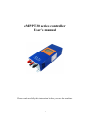
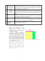
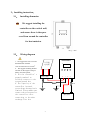
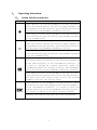
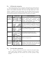
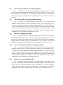
1
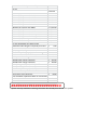
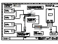
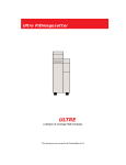
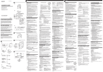
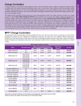
M&R Controls (UK) Limited
Electrical Control Specialist
Thank you for your interest in our Narrow Boat solar packages.
You will find below:
1 – A price list for the Tilt & Flat packages from 100 – 600 watt
2 – Price for the Tilt & Turn system
3 – Details of the equipment supplied
The prices all include delivery to your boat or home
Payment can be made by cheque or debit card prior to delivery or if you
prefer to pay by CASH on the day of delivery you can choose from the
following options:
a) Free fitting of any system
OR
b) 25% discount on any system if you self fit
NEW PRODUCT
MPPT Solar Charge Controller now available (details attached)
UP-Grade any package to the MPPT – See price list – Page 4
M&R
Controls (UK) Limited
Unit 1D,
Stonebroom Industrial Estate
Stonebroom
Derbyshire
DE555 6LQ
01773 875795
Email: [email protected]
Notes on MPPT
Please be careful if looking at other MPPT systems. There are other low cost units stating they are
MPPT but in fact they are not. Our MPPT control is….
200 watt example in optimum conditions.
2 x 100 watt panels are plated at approximately 5.6 amp each, i.e. 11.2 amps
Our standard PWM has shown up to 12.5 amps
Our MPPT has shown up to 16 amps
If you happen to have more panels fitted and exceed 30 amp solar input (weather permitting), our
MPPT protects itself by backing it down to 30 amp and carries on.
We know of a few “so called” MPPT controllers which stop charging and trip, and they will not restart automatically. So unless you are there to manually reset they do nothing.
Notes on Solar Panels
Again please be careful when looking for solar panels.
All our panels are Mono-crystalline, 100 watt, 18 volt with Grade “A” cells.
There are a couple of good reasons for this;
1 – The physical size is manageable and fits nicely down the side of a narrow-boat
2 – THE VOLTAGE *
* The voltage is important. 18 volt is ideal for a 12 volt battery system. Larger panels can be much
higher voltage and are not really suitable for a 12 volt system. Some are 36 volt which we would use
on a 24 volt system but could be used on a 12 volt system. Some are even higher voltages and a
waste of money. Normal charge controllers will possibly trip on over-voltage and although you could
use a “voltage dropper” of some kind the wasted energy usually means a 250 watt panel produces
fewer amps than our standard 100 watt panel.
This is why we offer full systems!
Standard "Tilt & Flat" systems from 100 - 600 watt
Each panel is 100 watt mono-crystalline with high efficiency Grade "A" cells and measures 1200mm x
540mm x 30mm.
Each System consists of the following:
1 to 6 x 100 watt solar panel (qty obviously dependent on system) with 0.8 mtr length of preconnected solar cable with male / female solar connectors.
1 pair of aluminium mounting brackets for each panel with hand-wheel knobs and wing-nuts. These
brackets allow a 2 way tilt angle of about 35 degrees.
1 x 6mtr length of meta-flex cable (different lengths available on request) to connect solar panels to
solar charge regulator, with 2 pairs of pre-connected solar connectors at one end and boot
connectors at the other. The solar connectors are "handed" to ensure correct polarity. This cable is
flexible but very well protected, so is ideal to run along the roof.
4 x meta-flex cable clamps.
1 set of tri-start self tapping fixing screws and drill bit (qty varies with system) to fit solar brackets
and cable clamps.
1 tube of marine flex which can be used to bond the mounting brackets if you prefer not to drill, or
as a sealant in conjunction with the fixing screws.
1 x ABS weather proof box and meta-flex cable gland which can be used to aid cable entry into boat.
1 x CM 30 amp programmable solar charge regulator with graphical display showing battery voltage,
solar amps and much more.
1 x 3 mtr length red / black cable for connection between CM 30 and your battery bank. The red
cable is pre-fitted with an in-line fuse and both cable have 8mm ring connector at one end for
battery termination and boot connectors at the other end.
1 x 3mtr length of 16mm diameter split flexible conduit for battery cables.
1 set of documents including invoice, connection drawing, self-fit help guide, CM 30 instruction
booklet, panel specifications and warranty documents.
Narrow-Boat Solar Systems and Spares
Jan-13
List Price
100 watt full system with CM30
100 watt full system with MPPT
200 watt full system with CM30
200 watt full system with MPPT
300 watt full system with CM30
300 watt full system with MPPT
400 watt full system with CM30
400 watt full system with MPPT
500 watt full system with 60 amp MPPT
600 watt full system with 60 amp MPPT
200 watt Tilt & Turn System with CM30
200 watt Tilt & Turn System with MPPT
All with standard 6 mtr cable length
Additional cable length if required per metre
£
£
£
£
£
£
£
£
£
£
£
£
440.00
590.00
636.00
786.00
882.00
1,032.00
1,080.00
1,230.00
1,510.00
1,685.00
960.00
1,110.00
£
5.00
100 watt panel only
Tilt & Flat brackets (1 pair) + knobs + wing nuts
6 mtr metaflex cable inc' solar connectors
CM30 pwm solar charge controller
MPPT30 solar charge controller
MPPT60 solar charge controller
3 mtr battery cable (red + black) inc' fuse
3 mtr flexible split conduit
metaflex cable clamps (Pack of 5)
3 mtr metaflex expansion cable inc' connectors
and 2 into 1 solar connector
1 mtr metaflex expansion cable inc' connectors
and 2 into 1 solar connector
Marine Flex
£
£
£
£
£
£
£
£
£
175.00
40.00
55.00
75.00
225.00
320.00
18.00
8.00
4.00
£
40.00
£
£
30.00
7.00
Note: 20% discount available for payment by CASH on the day.
XXXXXXXXXXXXXXXXXXXXXXX
Spares are only available to existing customers who already have one of our systems.
Chinaland Solar Energy Co., Ltd.
合肥中南光电有限公司
Address: Feidong New City Economic Development Zone, Hefei, 231600,
Anhui Province, PR China
Tel/Fax: +86 551 7758555
Web: www.chnland.com
E-mail: [email protected]
Model :
Monocrystalline silicon solar panel
CHN100-36M
Specification:
Cell Efficiency
Monocrystalline silicon solar cells
125*125mm
18.31%
No. of cells and connections
36(4*9)
Dimension of module (mm)
1200*540*30mm
Weight
7.8kg
Cell
Limits
Operating temperature
-40 to+85℃
Maximum system voltage
1000 V DC
Temperature and Coefficients
Nominal Operation Cell Temperature
48℃±2℃
Current temperature coefficient ( %/k) 0.06±0.01
Voltage temperature coefficient ( mV/k)-(78±10)
Power temperature coefficient ( %/k)
-(0.5±0.05 )
Output
Type of output terninal
Junction box
Cable
LAPP ( 4.0mm²)
Asymetrical lengths
900mm(-) and 900mm(+)
Connection
CHN Plug Type IV
Characteristics
Model
CHN100-36M
Open circuit voltage (Voc)
22.459V
Optimum operating voltage ( Vmp )
18.2V
Short circuit Current ( Isc )
5.81A
Optimum operating current ( Imp )
5.44A
Maximum power at STC (Pm )
Power Tolerance
100Wp
-3%~+3%
eMPPT30 series controller
User’s manual
Please read carefully this instruction before you use the machine.
1
Content
1、 eMPPT series controller introduction ..................................................................................................1
1.1、Product features ...........................................................................................................................1
1.2、 Product function ..........................................................................................................................2
1.3、 technology introduction...............................................................................................................2
2、 Installing introduction ...........................................................................................................................2
2.1、 Installing dimension.....................................................................................................................2
2.2、 Wiring diagram............................................................................................................................3
2.3、 Wire & tool preparation..............................................................................................................4
2.4、 Installation process ......................................................................................................................4
3、 Operating instruction ............................................................................................................................5
3.1、 Button function instruction.........................................................................................................5
3.2、 LCD interface instruction ...........................................................................................................6
3.3、 View the battery parameters.......................................................................................................6
3.4、View and clear for the PV generating data ................................................................................7
3.5、 View and setting for the elevating voltage .................................................................................7
3.6、 Interface language choosing........................................................................................................7
3.7、 View and setting for the float charging voltage.........................................................................7
3.8、Restore the controlling defaults ..................................................................................................7
4、Breakdown and disposal.........................................................................................................................8
4.1、 Breakdown indication..................................................................................................................8
4.2、 Breakdown code meaning and disposal .....................................................................................8
5、 Technical parameters.............................................................................................................................9
2
1、eMPPT series controller introduction
1.1、 Features
The product adopts DC/DC converting technology and MCU technology.
It can adjust the working point of the solar panels array intelligently
to make the solar panels array realize the maximum power output. When
the external condition changes, eMPPT controller bases on the MCU theory
to track the maximum working point of the solar panels, this can improve
the using efficiency of the solar panels and decrease the solar generating
cost. Compared with average solar charge controllers, eMPPT can improve
the output efficiency of the solar panels by 5% to 30%(the output
increasing proportion affected by the factors such as the attribute of
the solar panels, environmental temperature and lighting conditions).
The product adopts in big screen lattice LCD, and uses the vivid icons
to indicate the parameters. It has concise and vivid interface. The
product is wall mounting installation. Please refer to chapter 2.1 for
the installing dimensions.
1.2、 Product functions
1
2
3
4
5
6
7
8
Functions
maximum power
point tracking
battery reversed
connection
protection
Anti-battery
reverse discharge
Anti-solar panels
reverse
connection
three-stage charge
control
float charging
voltage adjustable
temperature
compensation for
float charging
voltage
Elevating
charging voltage
adjustable
instruction
Adopting DC/DC converting technology and MCU technology to
realize the maximum output of the solar panels
Battery polarity connecting to the controller reversely (under the
condition not connecting solar panels) will not cause damage to
controller. It can work normally after connecting right.
When solar panels voltage is less than battery voltage, the battery will
not charge to the solar panels array.
Solar panels array polarity connecting to the controller reversely will
not cause damage to controller. It can work normally after connecting
right
Bulk、Absorption、Float
The users can adjust the float charging voltage within a certain scope.
Referring to the current battery temperature, take 25 ℃ as a
benchmark, the controller will compensate the float charging voltage
by -4mV/Cell/ ℃ . For 12V battery, compensation voltage
U=(t-25)*6*(-0.004)V ; For 24V battery, compensation voltage
U=(t-25)*12*(-0.004)V ; For 48V battery, compensation voltage
U=(t-25)*24*(-0.004)V
The users can adjust the elevating charging voltage within a certain
scope
1
9
1
0
1
1
1
2
1
3
solar panel input
deviated from
maximum power
point
internal
overheating
protection
When solar panel input power is over the acceptable power for the
controller, the controller will make the solar panel work deviated from
the maximum power to prevent itself damaged. So the controller
charges the battery by rated current.
When the internal temperature sensor detects excessive temperature,
the controller will stop working to prevent it being damaged. It will
resume working again when the internal temperature drops to a certain
degree.
temperature
When the internal temperature sensor detects the temperature
controlling fan
exceeding a certain degree, the controller will start the cooling fan until
the temperature drops to a certain degree.
panel over
When the input voltage of the solar panels exceeds the rated voltage,
voltage protection the controller will start protection automatically and stop working until
the input voltage resumes back to the normal scope.
remote
This optional function can make it possible to view and set the
controlling
parameters of the system on PC.
function
1.3、 MPPT technology introduction
MPPT means maximum power point
tracking. MPPT technology is the
technology to track the maximum power
point of the solar panels.
Under a certain condition of
temperature and light, the I-V curve of the
solar panels is as the right chart. The output
power of solar panel is product of I and V,
which means rectangular area of the points
on I-V curve for solar panels. See the right
chart, when the solar panels work at point
A, the output power is Pa=①+③; when
solar panels work at point B, the
output power is Pb= ① + ② .
Obviously, we can see Pb>Pa. The
purpose of MPPT technology is to
keep the solar panels always
working at point B when the outer
conditions change.
2
2、Installing instruction、
2.1、 Installing dimension
We suggest installing the
controller on the vertical wall,
and ensure there is the space
over 10cm around the controller
for heat emission.
(单位:mm)
2.2、 Wiring diagram
1. We suggest the user to use the
sheathed cable with the
cross-sectional area over 6mm2.
2. We suggest installing breaker
and fuse on the negative loop of
battery and solar panels.
3. Set the controller’s
ground terminal to
reliably connect to the
system ground bus.
4. The capacity of the
controller internal
overvoltage absorption is
limited. Please make sure
connect the solar panel to
the controller after
connecting to the mine
exchange line box.
eMPPT30XX
太阳能
电池组
防雷汇线箱
+
-
+
Fuse
Fuse
蓄电池组
3
-
2.3
Wire & tool preparation
⑴Prepare 6 mm2 black and red sheathed cables, each one roll. Prepare
several copper noses of Ф 6-6mm2 since controller adopts in Ф 6
terminals
⑵Hydraulic pliers(for crimping copper nose and cable) and 6 mm2 die,
one couple, 10mm wrench, 2 sets, Phillips screwdriver, 1 set,
cutting pliers, 1set
⑶Cut the cables according to the cabling requirement. Use hydraulic
and die to connect the copper nose and cables tightly, and prepare
all the cables well.
2.4 Installing process
⑴If breaker is installed in the battery loop, please make the breaker open. If fuse
is installed, please take out the fuse to prevent the phenomena of contact
ignition.
⑵Use the prepared cables to connect the +,- polarity of battery to the battery
terminals on the controller. Please make sure the connecting of the polarity is
correct.
⑶Use the prepared cables to connect the solar panel output of the main
convergence box to the solar panes terminals on the controller. Please make
sure the connecting of the polarity is correct.
⑷Use the prepared cables to connect the ground terminals to the ground box of
the system.
⑸Insert the temperature sensor to the right place on the controller.
⑹Close the breaker of the battery loop or insert the fuse of the battery loop, if the
controller LCD screen starts to show the signal, the controller will start to
work. And if the LCD has no signal, please check whether the connecting of
the polarity is correct, whether the connecting cables is in good condition,
whether the breaker is closed, whether the fuse is inserter. Wait until the LCD
has signal, and then go to next step.
⑺Close the breaker of the solar panels loop or insert the fuse of the solar panels
loop, then the controller LCD screen will show the solar panels voltage. If the
LCD shows the voltage is 0V, please check whether the breaker in the solar
panels loop is closed.
4
3、
Operating instruction
3.1、 button function instruction
button
+
-
OK
ESC
function instruction
Press shortly: At the non parameter setting interface,
press this button shortly can turn the page backward. At
the parameter setting interface, press this button shortly
will increase the parameter pending to be set.
Press long (over 5s): At the parameter setting interface,
press this button long can increase the parameter pending
to set automatically.
Press shortly: At the non parameter setting interface,
press this button shortly can turn the page forward. At
the parameter setting interface, press this button shortly
will decrease the parameter pending to be set.
Press long (over 5s): At the parameter setting interface,
press this button long can decrease the parameter pending
to be set automatically.
Press shortly: At the parameter setting interface, press
this button short can switch to the different parameters
in the same interface; at the confirmation interface, it
is used to confirm the current operation; under the
circumstances when the controller detects the breakdown,
press this button to the breakdown indication interface.
Press long (over 5s): At the parameter setting interface,
press this button long and enter inter setting interface,
and then press this button long to save the setting
parameter and exit the setting state.
Press shortly: At the parameter setting interface, press
this button to cancel the change for the current parameter;
at the confirmation interface, it is used to cancel the
current operation; at the non parameter setting interface,
it is used to switch to the main interface quickly.
Pressing this button long does not have any meaning.
5
3.2、 LCD interface instruction
The showing interfaces consist of 5 interfaces. Each interface has 4 lines. The first
line is the state indication line, and it indicates the working condition of the whole
system or the breakdown information. The icon of the upper right corner of each
interface is indication of the current interface. The first number means the current
interface, and the second one means the whole interface. Please refer to the following
form to check the functions of each interface(take 24V system as an example).
interface
interface
1(main
interface)
interface 2
Interface 3
interface icon
interface instruction
It shows the parameters of the system in
general: charging mode, breakdown code,
battery voltage, battery temperature, battery
charging current(controller will show this
interface after opening the system).
it shows the accumulative charging AH today,
the total accumulative charging AH. Operate at
this interface to clear the accumulative charging
AH.
The setting interface for elevating charging
voltage and float charging voltage.
Interface 4
The language choosing interface and
communication number setting interface
Interface 5
controller model, fixed version information and
default restoring interface
Breakdown
indication
interface
breakdown code indication and disposal
indication. This interface does not exist if no
breakdown. The interface comes after the main
interface if the system has breakdown.
3.3、 View the battery parameters
Use +,- button to switch to the first interface. It shows the solar panels voltage,
battery voltage, battery temperature, accumulative charging current for battery,
solar panels generating AH. This interface does not have parameter setting
function.
6
3.4、 View and clear for the PV generating data
Use +, - button to switch to the second interface. Press OK over 5s and it
enters into state of clearing the generating AH. Then press OK over 5s again to clear
the generating AH. Press ESC to exit the parameter setting interface. The controller
will exit the parameter setting interface automatically if no operation for the button
over 20s.
3.5、 View and set the elevating charging voltage
Use +,- to switch to the third interface. Press OK over 5s to enter into the
parameter setting interface. Then the parameter pending to set is flickering. Press +,
- shortly can adjust the parameter, and the adjusting margin is 0.1V. Press OK over
5s can save the modified data. Press ESC shortly can exit the parameter setting
interface without saving the modified data. Then press OK shortly to switch to the
next parameter setting. The controller will exit the parameter setting interface
automatically if no operation for the button over 20s.
3.6、 interface language choosing
Use +, - button to switch to the forth interface. Press OK over 5s to enter into
the language setting state. Use +,- button to switch to the language you want. Press
OK over 5s can save the modified data. Press ESC shortly will exit the parameter
setting interface without saving the modified data. The controller will exit the
parameter setting interface automatically if no operation for the button over 20s.
3.7、 View and setting for the float charging voltage
Use +,- to switch to the third interface. Press OK over 5s to enter into the
parameter setting interface. Then the parameter pending to set is flickering. Press +,
- shortly can adjust the parameter, and the adjusting margin is 0.1V. Press OK over
5s can save the modified data. Press ESC shortly can exit the parameter setting
interface without saving the modified data. Then press OK shortly to switch to the
next parameter setting. The controller will exit the parameter setting interface
automatically if no operation for the button over 20s.
3.8、 Restore the controlling defaults
Use +,- button to switch the interface to the fifth interface. Press OK for 5s to
enter into the interface of the restoring the controlling interface. Then press OK for
5s to restore the controlling defaults. Press ESC shortly to exit the parameter
setting interface without saving the modified data. The controller will exit the
parameter setting interface automatically if no operation for the button over 20s.
7
4、Breakdown disposal
4.1、 Breakdown indication
图1
图2
When controller detects the breakdown, it will send the breakdown code to the
LCD interface, in the first line (see picture 1), and then it will jump into the
suggestive interface to advise the customer to dispose the breakdown. At the
breakdown suggestive interface, press ESC short, and the controller will show the
interface before the breakdown.
4.2、 Breakdown and disposal
breakdown
cause of the breakdown
code
solar panel voltage exceeding rated
E101
maximum value
the
internal
temperature
of
E102
controller too high, the controller
stop charging the battery to prevent
the damage caused by overheating.
The controller will resume charging
after the internal temperature
recovers to a certain degree.
battery voltage is lower than LVP
E103
point, no protection
the temperature sensor for internal
E104
radiator
breakdown
or
not
connecting
battery voltage too high, no
E105
protection
8
disposal
checking whether the solar panels
connect too much
checking whether the emission holes
blocked or cover, whether the
controller working condition to high
disconnect other charging appliances
5、Technical parameters
model
solar panel input
voltage scope
maximum power
input
point voltage
tracking scope
solar panel input
route
rated working
voltage
maximum charging
current
no load loss
charging mode
float charging
output
voltage
temperature
compensation for
float charging
voltage
absorption
charging voltage
temperature scope
protection
functions
others
cooling way
optional function
working
temperature scope
working altitude
working humidity
scope
volume
weight
storage
temperature scope
technical parameters
eMPPT3024Z
eMPPT3048
≤70V
≤130V
12V~70V(12V)
24V~70V(24V)
48V~130V
1 route
1 route
12V/24V auto switch
48V
30A
30A
≤30mA
≤30mA
(Bulk、Absorption、Float)
27.6V(adjustable)
55.2V(adjustable)
-4mV/cell/℃
-4mV/cell/℃
28.8V(adjustable)
57.6V(adjustable)
-20℃~+70℃
-20℃~+70℃
① battery reverse connection function
② battery reverse discharging function
③ solar panel reverse connection function
④ solar panel input over voltage protection
⑤ radiator overheat protection
⑥input over power deviated from maximum power point
thermostat active cooling
(RS485 or RS232)remote controlling function
-10℃~+50℃
≤3000m
0~90%, no condensation
380mm*150mm*100mm
2.5 Kg
2.6 Kg
-30℃~+80℃
9