1
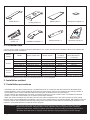
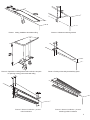
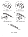
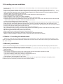
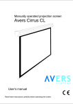
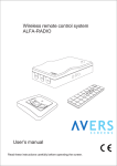
Avers Stratus 2 In-ceiling installation kit User’s manual Read these instructions carefully before operating the screen. Dear Customer, Thank you very much for the purchase of our product. The manual booklet contains all operation information you may require to install properly and operate the screen. We hope it will help you to get the most performance and enjoyment of your new screen. Enjoy time with the Avers Screens product. SAFETY INFORMATION NOTICE: Important safety information. Follow the instructions described in the operating manual for safety reasons. After reading the manual, please store it in a safe place just in case you need it in the future. Table of contents: 1. Safety rules 1.1. Declaration of Conformity CE 2. Product specification 2.1. Contents of package 2.2. Technical data 3. Installation method 3.1. Installation directions 3.2. Ini-cCeiling installation 4. Screen maintenance 5. Warranty conditions 1. SAFETY RULES SAFETY INFORMATION NOTICE: Important safety information. It is important for the safety of persons to follow these instructions. After reading the manual, please save it just in case of need in the future Periodically examine the screen installation for imbalance and signs of wear or damage to cables. Do not use if repair or adjustment is necessary. Do not attach any objects to the screen’s bottom bar. Screen damage and/or person injury danger. All installation work should be carried out by the qualified technician. Improper installation of the screen can cause device damage or health breakdown. Ceiling/wall installation can be done with the originally supplied mounting brackets dedicated for this model only. Always follow the instructions described in the operating manual. 2 1.1. Declaration of Conformity CE Manufacturer’s Declaration of ConformityCE AVERS Screens Sp. z o.o. Under it’s own responsibility declares: All screensand accessories mentioned below are manufactured in Polandaccording to the essential safety requirements of Council Directive 98/79/WE Projection screens: Stratus 2, Stratus, Focus, Cumulus X, Solar, Solaris, Contour, Altus, Cirrus CL, Cirrus X, Cirrus X Crank Projector mount brackets: Alumount, Promount, SimpleMount, ShortMount, Prolift The above mentioned products are in conformity with the European Directives and especially with the norms: PN-EN 55014-1:2007(U) PN-EN 50082-1:1997 PN-EN 60335-1:2004 PN-EN 61000-3-2:2007 PN-EN 61000-3-3:1997 IEC 60335-2-97:2007 2. Product specification Set of components required for hidden installation of Stratus 2 or Stratus 2 Tension screen in the false ceiling. It is designed for upper-class business applications and sophisticated Home Cinema applications. 2.1. Contents of packaging Please, check carefully if any physical damage of the screen has not happen during transportation. Inspect the package for all accessories presented below: M8 x4 M8 x 10 M8x20 x 2 M8x40 x 4 M5x8 x 4 Masking profile x 2 Nuts and Screws Screen bracket x 2 Ceiling bracket (40cm) x 2 3 Profile latch x 2 Locking profile x 2 Masking tile x 2 Neodymium magnet x 4 Ceiling bracket anchor x 6 Installation template x 1 Tubular wrench x 1 Operation manual x 1 2.2 Technical Data Please use the table to check Inceiling kit dedicated for your screen and size of the installation whole to be cutted at the false ceiling for screen installation. Screen family Stratus 2 Stratus 2 Tension Model Picture aspect ratio Border version Dedicated in-ceiling installation set False ceiling whole dimensions*) D x w [cm] 18/10, 18/14, 18 21/12, 21/16, 21 24/14, 24/18, 24 27/15, 27/20, 27 30/17, 30/23, 30 18/10, 18/14, 18 21/12, 21/16, 21 24/14, 24/18, 24 27/15, 27/20, 27 16:9, 16:10, 4:3, 1:1 16:9, 16:10, 4:3, 1:1 16:9, 16:10, 4:3, 1:1 16:9, 16:10, 4:3, 1:1 16:9, 16:10, 4:3, 1:1 16:9, 16:10, 4:3, 1:1 16:9, 16:10, 4:3, 1:1 16:9, 16:10, 4:3, 1:1 16:9, 16:10, 4:3, 1:1 no, BB type, BT type no, BB type, BT type no, BB type, BT type no, BB type, BT type no, BB type, BT type BB type, BT type BB type, BT type BB type, BT type BB type, BT type INC KIT 1 INC KIT 2 INC KIT 3 INC KIT 4 INC KIT 5 INC KIT 2 INC KIT 3 INC KIT 4 INC KIT 5 196 x 14 225 x 14 260 x 14 288 x 14 322 x 14 225 x 14 260 x 14 288 x 14 322 x 14 *) Check the length of your screen’s case (plastic side caps removed) before you begin to cut installation hole at the false ceiling. the lenght of the hole sholud be 10cm longer then screen’s casing. The hole length tolerance of +/-1cm is acceptable. 3. Installation method 3.1 Installation precautions - Installation work should be carried out by a qualified technician in accordance with the instructions described below. - Fixed installation of the screen should be done with use of the screws and anchors suitable for the ceiling materials at the installation place. Anchors delivered with the Inceiling Kit are dedicated for concrete ceilings. - Check carefully after installation if the screen is perfectly leveled. Do not roll out the screen not installed in horizontal position. In case the screen leveling is not perfect correct the installation. - When the distance between the real ceiling and the false ceiling is different than than 40cm metal rods of the ceiling brackets have to be modified before installation. You must cut or extend them to the required length. M8 extension rods are not part of the kit and should be purchased separately at the construction market. M8 nuts and bushings required for rod extension are bundled with the in-ceiling kit for this purpose. !!! CAUTION!!! Check false ceiling leveling and flatness before begining screen installation. False ceiling must be 100% horizontal and flat, otherwise either screen operation will not be posible, either installation appearance will be bad. Screen installation performed in the false ceiling not meeting requirements described above will result in improper screen operation or physical projection surface damage. 4 Picture.1 Cutting installation slot at false ceiling Picture 3 Preparation of ceiling bracket and installation template for pointing of fixing points at the real ceiling Picture 5 Screen installation - phase 1 Initial installation Picture.2 H distance measuring method Picture 4 Pointing of the ceiling bracket fixing points Picture 6 Screen installation - phase 2 Masking profiles installation 5 Picture 7 Screen installation - phase 2 Masking profiles locking Picture 9 Screen installation - phase 4 Installation of masking profile latches Picture 8 Screen installation - phase 3 Screen installation level final adjustment Picture 10 Screen installation - phase 5 Masking tiles installation Picture 11 Screen installed 6 3.2 In-ceiling screen installation - Trace the shape of the screen’s installation slot at the false ceiling. Cut out the whole according to the traced shape (see Picture 1). - Check the “H” distance between the real ceiling and the bottom surface of the false ceiling (see Picture 2) - Prepare ceiling bracket and the installation template to point the ceiling’s bracket fixing points at the real ceiling. Modify length of the ceiling bracket’s rods if needed. Distance between the ceiling bracket foot and the installation template should be equal with H distance (see Picture 3) - Trace the ceiling bracket fixing points (see Picture 4) and drill holes for the fixing anchors. - Fix the ceiling brackets to the real ceiling. - Prepare projection screen case for in-ceiling installation: a) Remove plastic casette endcaps, securing screws must be removed before. b) Sweep out decorative tapes installed at the front and rear sides of the screen case. We recommend to roll them and store at secure place in case they would be needed in the future. c) Fix the screen brackets to the screen case sides. d) Fix temporary locking profile to the screen bracket with prowided screw (see Picture 5). Do not tight the fixing screw. - Install the screen at the ceiling brackett rods temporary, secure the screen from falling down with self locking nuts (provided with the kit). Fixing nuts should be turned 6 times for safety, bottom part of the screen case should be lowered a few cm from the false ceiling surface (see Picture 6). - Fix masking profiles at the screen case slots (see Picture 6 and Picture 7). - Lift up the screen case by turning nuts at the ceiling bracket rods. Masking profiles should abut the false ceiling surface. - Tight the screws at locking profile to lock the screen case. - Slip masking profile latches at the position (see Picture 9) - Apply magnets at the masking profile latches (see Picture 10) - Apply masing tiles at the positions at both ends of the screen case (see Picture 10) - Hidden in-ceiling installation of Stratus 2 screen at the false ceiling is finished succesfully. 4. Stratus 2 In-ceiling kit maintenance Stratus 2 In-ceiling kit do not require periodical service maintenance. Clean dust from visible surfaces with dry soft cloths. If needed use moisturized cloth with soft detergent to remove stains. After stain removal dry the cleaned surface with cloth carefully. 5. Warranty conditions 1) Avers screens warranty period is 24 months from the date of purchase confirmed with the original purchase invoice. 2) Extended warranty period for electric engine is 60 month. 3) Surety commits to fix free of charge any failures (component or production defects) of the product which appear during warranty period. 4) Warranty exclusions : a) the failures caused by the usage of the screen against the rules described in operation manual, b) the failures caused by improper storage or transportation, c) mechanical defects of the screen other than mentioned at point 3), d) damages caused with overvoltage at power network, e) deinstallation and reinstallation of the screen. 5) Avers Screens Service department will remove all defects within 21 days after receiving the demaged product. 6) Warranty claims should be passed to the screen supplier (dealer). 7 Manufactured after 13.08.2005 This symbol on the products and/or accompanying documents means that used electrical and electronic products should not be mixed with general household waste. Disposing of this product correctly will help to save valuable resources and prevent any potentialnegative effects on human health and the environment which could otherwise arise from inappropriate waste handling. Please contact your local authority for further details of your nearest designated collection point. Wersja 30.07.2012