1
Microprocessor-Based
Auto-tuning Control
( User’s Manual)
Watlow Controls, 1241 Bundy Blvd., P.O. 8ox 5580, Winona, MN 55987-5580, Phone: 507/454-5300, Fax: 507/452-4507
W985-MA58-9307
February, 1993
Supersedes:
W985-MA70-9043
$10.00
Made in the U.S.A.
0 Printed on Recycled Paper
0
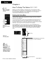
How to Use the Manual
First..
This manua/ will make
your job easier. Reading it and applying the informa-
tion is a good way to become familiar with the Series 980/985.
Starting Out
Chapter 1, Page 4.
Install/Wire
Chapter 2, Page 6.
Front Panel
Chapter 3, Page 22.
Set Up
Chapter 4, Page 24.
Tuning
Chapter 5, Page 29.
Appendix
Specifications, Page 34
Cali bration
Glossary
Warranty
An overview:
Notes
NOTE:
Details of a *‘Note**
appear here, in the
narrow box on the
outside of each page.
LLL
CAUTION:
Details of a “Caution”
appear here, in the
narrow box on the
outside of each page.
0
WARNING:
Details of a “Warning”
appear here, in the
narrow box on the
outside of each page.
The user’s manual contains informational notes to alert you to important details.
When you see a note icon, look for an explanation in the margin.
1 orJ3
Safety Information
This user‘s manual also has boldface safety information notes to protect both
you and your equipment. Please be attentive to them. Here are explanations:
AT
The Caution symbol (exclamation point) in the wide text column alerts you to a
“CAUTION,” a safety or functional hazard which could affect your eguipment or
its performance. A full explanation is in the narrow column on the outside of
the page.
0
The Warning symbol (lightning bolt) in the wide text column alerts you to a
**WARNING,” a safety hazard which could affect you and the equipment. A full
explanation is in the narrow column on the outside of the page.
Your Feedback
Your comments or suggestions on this manual are welcome, please send them
to: Technical Writer, Watlow Winona, Inc., 1241 Bundy Blvd., Winona, MN
55987, or phone 507-454-5300. The Watlow Series 9801985 User’s Manual
and integral software are copyrighted by Watlow Winona, Inc., © 1988, with all
blrO293
rights reserved.
2
WATLOW Series 9801985 User’s Manual
How to Use the Manual
Figures, Table, Charts
Chapters
page
Item
4
4
5
5
Chapter 1
Starting Out With The Watlow Series 980/985
General Description
Putting Your Control To Work
Overview of the Series 980/985 Menus
6
6
6
6
7
9
9
10
11
13
21
Chapter 2
How To Install And Wire The Series 980/985
System Planning
Sensor Installation Guidelines
Installation Guidelines For Preventing Noise
Noise
Checking For Ground Loops
Noise Suppression Devices Available..
Line Filtering Configurations For Controls
How To Install The Series 980/985
How To Wire The Series 980/985
System Wiring Example
Chapter 3
22 How To Use The Keys and Displays 22 Series 980/985 Displays & Load LED’s
23 Series 980/985 Keys
24
24
25
26
27
28
Chapter 4
How To Set Up The Series 980/985 Entering Set Up Menu
Set Up Parameters
Set Up Menu
Operation Parameters
Operation Menu
29
29
30
31
31
32
Chapter 5
How To Tune And Operate Tuning - Manual
Tuning - Automatic
Manual and Automatic Operation
Using Alarms
How To Deal With Error Codes
34
34
36
37
38
38
41
42
42
43
43
Appendix
Specifications
Model Number Information
Calibration Menu
Calibration Procedures
Glossary
Index
Returns
Shipping Claims
Warranty
Watlow Controls
H o w to Use the M a n u a l
page
Item
Figure
1
2
3
4
5
6
7
8
9
10
11
12
13
14
15
16
17
18
19
20
21
22
23
24
25
26
27
28
29
31
32
33
34
4
5
10
10
10
12
12
13
13
14
14
15
15
16
16
l?
17
18
18
19
19
20
20
21
22
23
24
24
27
31
32
37
38
Series 980/985 Input & Output Overview
Overview of the Series 980/985
Differential Mode Filter Wiring
Common Mode Fifter Wiring
Combination filter Wiring
Series 980/985 Panel Cutout Dimensions
Series 980/985 Dimensions
115 VAC Power Wiring
230 VAC Power Wiring
Thermocouple Wimg Diagram
Process Wiring Diagram
RTD (2 wire) Wiring Diagram
RTD (3 wire) Wiring Diagram
Solid State Relay, Output 1 Wiring
DC Output 1 (Open Collector) Wiring
6 Amp Relay, Output 1 Wiring
O-lOVDC, Output 1 Wiring
4-2OmA, Output 1 Wiring
O-2OmA, Output 1 Wiring
0-5VDC, Output 1 Wiring
S.S. Relay, Output 2 Wiring
DC Output, Output 2 Wiring
6A Mechanical Relay, Output 2 Wiring
System Wiring Example
Series 980/985 Displays
Series 980/985 Keys
Entering the Set Up Menu
The Set Up Menu
The Operation Menu
Alarm Display Examples
Error Code Display Examples
The Calibration Menu
Calibration Parameters
9
39
Noise Suppression Device Ratings
RTD Settings
Tables
1
2
26
26
28
Set Up Menu Prompts/Description
Input Ranges
Operation Menu Prompts/Description
Charts
1
2
3
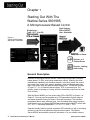
Chapter 1
Starting Out With The
Watlow Series 9801985,
A Microprocessor-Based Control
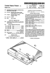
Single Input Type J, K, T, N or Pt2
Dual OutputsPID or ON/OFF
User Selectable
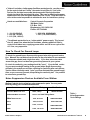
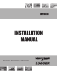
Flgure 1 Series 980/985 Input
and Output Overview
Heat, Cool or Alarm
Output 1 or 2
Percent Power
Output 1, Heating
Auto-tuning
General Description
Welcome to the Watlow Series 980/985, a dual output, single input, microprocessor-based, 1/8 DIN, auto-tuning temperature control, featuring the Automatic/Manual capability with bumpless transfer. In the Auto mode, the control
has closed loop control with sensory feedback, while the Manual mode has
open loop control with user defined output power level. The 980/985 accepts
a Type J, K, T, N, or Platinel2 thermocouple, RTD, or process input. The
primary output is Heating or Cooling, while the secondary output can be Heat,
Cool or Alarm.
With the Series 980/985 you can select either PID or ON/OFF for Output 1 or
Output 2. You may input a complete set of PID parameters for both outputs,
and select automatic tuning for Output 1 from the front panel. This includes
proportional band, reset, rate and cycle time. By setting either output’s proportional band to zero, the Series 9801985 becomes a simple ON/OFF control with
a 3°F or 1.7°C switching differential, 0.3°F or 0.17°C for 0.1 ° RTD.
Operator-friendly features include automatic LED indicators to aid in monitoring
and set-up, as well as a calibration offset at the front panel. The Watlow
Series 980/985 automatically stores all information in a non-volatile memory.
4
WATLOW Series 980/985 User’s Manual
Getting Started, Chapter 1
Putting Your Control To Work
To put your Series 980/985 to work, we suggest the following steps:
Read the User’s Manual.
Plan your installation and wiring.
Cut the panel mounting hole and install the control.
Wire your Series 980/985 to the system.
Start the system and tune the Series 980/985.
Make final adjustments to the control parameters and record the data.
That’s all there is to it.
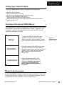
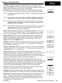
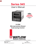
Overview of the Series 980/985 Menus
Before getting into the details of installing and wiring the Series 980/985, take a
look at Figure 2, and at the three different menus. “Setup”, “Operation”, and
“Calibration”. After you feel comfortable with the names and their functions,
move on to installation and wiring.
Setup
Operation
Calibration
Configure the 980/985’s features to your
application. Establish levels of operator
access, input type, units of measure, low and
high range limits, and Output 2 configuration.
Figure 2 Overview of the
Series 980/985.
Enter the set point and the PID tuning values
and alarm set points here. Parameters for
proportional band, reset, rate and cycle time for
Outputs 1 and 2; alarm low and high; deadband: calibration offset and auto-tune
are here also.
Supply various input signals to the
Series 980/985, and it performs autocalibration. Calibration procedures
should only be attempted with
proper equipment and by qualified
personnel.
Where To Go From Here
If your Series 980/985 is already installed and wired, go directly to “How to Use
the Keys and Displays”, Chapter 3. If not, turn the page to Chapter 2, “How to
Install and Wire the Series 980/985”, and proceed from there.
Getting Started, Chapter 1
WATLOW Series 980/985 User’s Manual
Chapter 2
How to Install and Wire the
Series 9801985
System Planning
This chapter tells you how to install the Series 980/985. All mounting and
wiring information is right here. Because Watlow controls are thoroughly
tested and "burned in" before leaving the factory, the Series 980/985 is ready
to install when you receive it.
But before you begin working, read through this chapter to gain an understanding of the entire installation. Consider sensor installation carefully. You’ll need
to look at the noise reduction guidelines before making your panel cutout.
Sensor Installation Guidelines
We suggest that you mount the sensor at a location in your process or system
where it reads an average temperature. Put the sensor as near as possible to
the material or space that you want to control. Air flow past this sensor should
be moderate. The sensor should be thermally insulated from the sensor
mounting.
Installation Guidelines For Preventing Noise
For improved electrical noise immunity, install the Series 980/985 as far away
as possible from motors, relays, and other similar noise generators.
Do not run low power (sensor input) lines in the same bundle as AC power
lines. Grouping these lines in the same bundle can create electrical noise
interference which may result in error codes in the Series 980/985.
The Culprit
Most noise problems stem from wiring practices. They’re the major means of
coupling noise from its sources to the control circuit The following information
will tell you how to eliminate or decrease noise.
An Information Resource
An outstanding resource for information for wiring guidelines is the IEEE
Standard No. 518-1982 and is available from IEEE, Inc. 345 East 47th Street,
New York, NY 10017.
6
WATLOW Series 980/985 Users Manual
Install and Wire, Chapter 2
Noise Sources
Switches and relay contacts operating inductive loads such as motor, coils,
solenoids, and relays, etc.
Thyristors or other semiconductor devices which are not zero crossover-fired
(randomly-fired or phase angle-fired devices).
All welding machinery.
Heavy current carrying conductors.
Fluorescent and neon lights.
How To Decrease Noise Sensitivity
Physical separatlon and wire routing must be given careful consideration in
planning the layout of the system. For example, A.C. power supply lines
should be bundled together and physically kept separate from input signal
lines (sensor lines). A 12 inch minimum separatlon is usually effective. Keep
all switched output signal lines (high power level) separate from input signal
lines (sensor lines). Cross other wiring at 90° angles whenever crossing lines
is unavoidable.
Another important practice is to look at the system layout and identify electrical noise sources such as solenoids, relay contacts, motors, etc., and where
they are physically located. Then route the wire bundles and cables as far
away as possible from these noise sources. Don’t mount relays or switching
devices close to a microprocessor control. Don’t have phase angle-fired
devices in the same electrical enclosure or on the same power line with the
control.
Shielded cables should be used for all low power signal lines to protect from
magnetic and electrostatic coupling of noise. Some simple pointers are:
• Whenever possible, low level signal lines should be run unbroken from
signal source to the control circuit.
• Connect the shield to the control circuit common at the control end only.
Never leave the shield unconnected at both ends. Never connect both
shield ends to a common or ground.
• If the shield is broken at some termination point and then continued on, the
shield must be connected to maintain shield continuity.
• If the shield is used as a signal return, no electrostatic shieldlng should be
assumed. If this must be done, use a triaxed cable (electrostatically
shielded coaxial cable).
Twisted pair wire should be used any time control circuit signals must travel
over two feet or when they are bundled in parallel with other wires.
The size or gauge of wire should be selected by calculating the maximum
circuit current and choosing the gauge meeting that requirement. Using
greatly larger wire sizes than required generally will increase the likelihood of
electrostatic (capacitance) coupling of noise.
Install and Wire, Chapter 2
WATLOW Series 980/985 User's Manual
7
• Ground loops must be eliminated in the entire control system. There are
obvious loops which can be spotted by studying the"as-built" wiring diagram.
There are also the not-so-obvious ground loops that result from the technique
of connecting internal circuit commons in the manufacturer's equipment. An
example of this would be if a control circuit is designed to work with a
grounded sensor input.
• Do not daisy chain A.C. power (or return) lines, or output signal (or return)
lines to multiple control circuits. Use a direct line from the power source to
each input requiring A.C. power. Avoid paralleling L1 (power lead) and L2
(return lead) to load power solenoids, contactors, and control circuitts. If L1
(power lead) is used to switch a load, L2 (return lead) will have the same
switched signal and could couple unwanted noise into a control circuit.
• Grounding the chassis of each piece of equipment in the system is very
important. The simple practice of connecting each individuai chassis to the
overall equipment chassis immediately adjacent to that piece, and then tie all
the major chassis ground terminals together with one lead (usually green
wire) to ground at one single point will work best. Don’t connect ground to
the control case if the control is mounted in grounded enclosure (prevent
ground loops).
• Do not confuse chassis grounds (safety ground) with control circuit commons
or with AC. supply lines L2 (return or neutral line). Each return system
wiring must be kept separate. Be absolutely sure chassis ground (safety) is
never used as a conductor to return circuit current
How To Eliminate Noise
• Use “snubbers” ("QUENCHARC™") to filter out noise generated by devices
such as relays, relay contacts, solenoids, motors, etc. A snubber is a simple
filter device using a 0.1µf, 600 volt, non-polarized capacitor in series with a
100 ohm, 1/2 watt resistor. The device can be used on A.C. or D.C. circuits
to effectively dampen noise at its source.
• The general purpose Watlow snubber, described above, is 0804-0147-0000.
For other ‘QUENCHARC” sizes contact
PAKTRON
P.O. Box 5438
Lynchburg, VA 24502
Phone: 804-239-6941
• Metal Oxide Varistor (MOV) can be used to limit voltage “spikes” that
occur on the A.C. supply lines as a result of lightning strikes, switching large
motors, etc. The MOV is available in several varieties and for 115 or 230
volt lines. The device dissipates the voltage “spikes” to ground and in doing
so repeatedly, deteriorates its ability to function. MOVs have a limited life.
• Watlow stocks several MOVs. See Table 1.
8
WATLOW Series 980/985 User's Manual
Install and Wire, Chapter 2
"Islatros" and other similar power line filters are designed to carry the power
for the control circuit and “buffer” the control circuit from A.C. line noise.
Devices like the lslatrol use media (electromagnetic filtering) other than
electric circuits to filter out electrical noise. Take care in matching the power
capabilities of the filter with power demands of the circuit. Keep line filters as
close to the control as possible to minimize the area for interference pick up.
lslatrols are available from:
I - 101 (1A,l20VAC)
I - 105 (5A, 120VAC)
I - 115 (15A, 120VAC)
Control Concepts Corporation
328 Water Street
P.O. Box 1360
Blnghamton, NY 139O2-1360
Phone: 607/724-2464
I - 202 (2.5A, 208/240VAC)
I - 207 (7.5A, 208/240VAC)
The ultimate protection is an “uninterruptable” power supply. This 'senses'
the A.C. power line; when the line fluctuates, a battery powered 6OHz inverted circuit takes over, supplying power within one-half to one cycle of the
A.C. line; very expensive.
How To Check For Ground Loops
To check for ground loops, disconnect the ground wire at the ground termination. Measure the resistance from the wire to the point where it was connected.
The ohmmeter should read a high ohm value. If you have a low ohm value
across this gap, there is at least one ground loop present in your system.
Or check for continuity; your reading should be "open”. If you do find continuity, you must now begin looking for the ground loops. Begin disconnecting
grounds in the system one at a time, checking for continuity after each disconnection. When continuity reads "open” you have eliminated the ground loop(s).
Also, as you reconnect grounds, keep making the continuity test. It is possible
to reconnect a ground loop.
Noise Suppression Devices Available From Watlow
Watlow Controls stocks a few key noise suppression parts. You may order
these by calling your local Watlow distributor.
Item
Electrical Ratlngs
Part Number
Common Mode Line Filter
25OV, 3 Amp
Differential Mode Line Filter
Refer to the lslatrol listing above.
Metal Oxide Varistor
15OV, 80 Joule
0802-0273-0000
MOV
13OV,38 Joule
0802-0304-0000
8
0
2
0
-3
0
4
0
-0
0
0
MOV
275V, 75 Joule
0802-0266-0000
MOV
275V, 140 Joule
0802-0405-0000
Install and Wire, Chapter 2
0804-0196-0000
Table 1 NoiseSuppressIon
Device Ratings
WATLOW Series 98O/985 User’s Manual
9
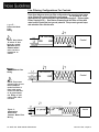
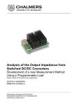
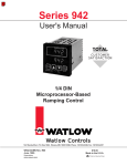
Line Filtering Configurations For Controls
Figure
3-
These three diagrams show you filter configurations for removing input power
noise. Choose the one best suited for your system. For very dirty or critical
applications- use a microcomputer-regulated power supply or Uninterruptable
Power Supply(U.P.S.) Don’t fasten common mode line filters or filters with
metal cases to metal that is at ground potential. This prevents ground loops
and maintains filter effectiveness.
Differential Mode
Filter
Wiring
Ll
.
D.M. Line Filter
Control
NOTE: Keep filters
12 inches or less
from the control.
Minimize the line
distance where
nolse can be reintroduced to
control.
Common Mode Filter
Wiring
C.M. Line Filter
Control
2
NOTE: To prevent
ground loops do not
fasten common
mode line filters or
filters with metal
cases to metal that
is at ground potentlal. Doing so will
reduce filter effectiveness.
Figure 5 Combination
Differential/
Common Mode Filter
Wiring
I
Ground
10 WATLOW Series 980/985 User's Manual
Control
Install and Wire, Chapter 2
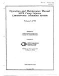
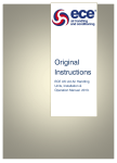
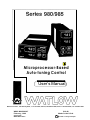
How to Install the Series 980/985
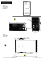
Figures 6,7 and 8 provide the Series 980/985’s panel cutout and dimensions.
Do not, however, make your panel cutout until you are sure that you are
placing the control in the best location. Read the noise guidelines at the
beginning of this chapter before installing and wiring the Series 980/985.
1. Place the panel cutout in the desired location. Figure 6 shows you the
panel cutout dimensions.
2. To install, carefully insert the Series 980/985 into the panel cutout.
the unit in until the bezel is seated securely against the panel.
Push
3. Included with your control are two adjustable mounting brackets; one for the
top and one for the bottom of the control case. Installing the mounting
brackets requires access to the back side of the panel.
1 NOTE:
Removing the Series
980/985 chassis
from its case may
make mounting
easier.
On the top and bottom of the case are a series of slots running the length of
the case. The first two shorter slots are for attaching the mounting brackets. Figure 8 shows a side view with both mounting brackets.
4. Loosen the mounting bracket screws with a Phillips screwdriver far enough
to allow for the panel thickness.
5. Make sure that each bracket is placed in the first two slots from the front of
the control, with the head of the screw facing the back of the control. Refer
to Figure 8 for screw and bracket placement.
6. To attach, place the bracket into the slots (head of the screw facing the
back of the control and push backward, securing the brackets to the control
case. Do the same for the other side of the control.
7. Make sure the Series 980/985 case is seated properly. Tighten the installation screws firmly against the panel to secure the unit in place.
8. To remove the unit from its enclosure, loosen the captive screw at the
bottom of the 980/985’s front panel with a Phillips screwdriver. Pull the unit
from its case.
9. To release the mounting brackets, push the brackets forward and pull out to
release them from the control case.
Install and Wire, Chapter 2
WATLOW Series 980/985 User’s Manual
11
Panel Cutout
Max.Panel
Thickness
0.50 (12.7mm)
Figure 6 Series 980/985
Panel Cutout
Dimensions
~
3.82 +0.03 - 0.00
(92mm + 0.8)
Load Power
indicators V
T
I .89
(48.0 mm
Figure 7 Series 980/985
Dimensions
Panel
_
12 WATLOW Series 9801985 User’s Manual
Adjustuble
‘Install and Wire, Chapter 2
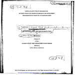
How to Wire the Series 980/985
The Series 980/985 wiring is illustrated by model number option. Check the
unit sticker on the control and compare your model number to those shown
here and also the model number breakdown in the back of this manual.
Series 980/985 internal circuits appear “inside“ the line drawing of the 980/985,
while connections and terminal designations appear “outside” the line drawing.
All outputs are referenced to a de-energized state. The final wiring figure is a
typical system example.
All wiring and fusing should conform to the National Electric Code and to any
locally applicable codes as well.
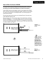
When you apply power without sensor inputs on the terminal strip, the Series
980/985 will display “- - -” in the Upper display, and a "O" in the Lower display.
Press the AUTO/MANUAL key twice, and an ER 7 is displayed for one second.
This error indicates an open sensor. Remove power to the control and connect
the sensor properly, see Page 14.
Figure 8 115 VAC Power
Wiring
II II
Jumper #4 to #6 and
Jumper #5 to #7 for
115 VAC operation
0
II 0
Install and Wire Chapter 2
Jumper # 5 to # 6 for
230 VAC operation
L2
Earth Ground
0
CAUTION:
To avoid potential
electric shock, use
National Electric
Code (NEC) safety
practices when
wiring and connecting this unit to a
power source and to
electrical sensors or
peripheral devices.
Figure 9 230 VAC Power
Wiring
WATLOW Series 980/985 User’s Manual
13
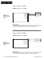
lnput Options “1“, “2” & “3”, Thermocouple Input
Terminals 18 & 20
Figure 10 Input Options “1”,
**2* & *3’, Thermocouple Wiring
Diagram.
I
Model # 98– A - 1 _ _ - 0-0000
98_A-2 – – 0-0000
98_A-3- – – 0-0000
II II
1
NOTE:
You must use an isolated or ungrounded thermocouple if an external 4-20mA
output device with a non-isolated circuit common is connected to the 4-20mA
output.
Extenslon wire for thermocouples must be of the same alloy as the thermocouple
itself to limit errors.
These input connections are used in conjunction with your units sensor
type. (Thermocouple and RTD only)
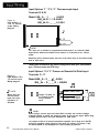
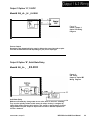
Input Options “2’ & “3”, Process or Remote Set Point Input
Terminals 15 - 17
Flgure 11 Input Options "2" &
"3" Process Input
Wlring Diagram.
Model #98_A - 2 _ _ 0 - 0000
98_A - 3 _ _ 0 - 0000
1
NOTE:
When using a 42OmA process
Input, the input
impedance is
24 9 ohms
0
II Jumper Terminal 16
to Terminal 17 when
using a 4-20mA
input.
fl
0-5VDC 4-20mA INPUT
16
17
0-5VDC, 4-20mA INPUT
Input
Voltage
.
J3
NOTE:
When using a process input such as O-5VDC or 4-2OmA, the rL and rH settings
scale the display to match the measured range of the process signal. When using
a 0-5VDC process input, the input impedance is 100K ohms.
An example of this is: A pressure transducer operates over a range of 0 - 300 PSI,
delivering a 4-20mA output signal for this range. By setting rL= 0 and rH = 300,
the Series 980/985 is now displayed as a direct reading of pressure.
14
WATLOW Series 980/985 User’s Manual
Install and Wire, Chapter 2
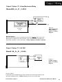
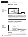
Input Options “2” & " 3 " RTD - 2 Wire
Terminals 12 - 14
ModeI#98 _ A - 2 _ _0-0000
98_A-3_ _0-0000
Figure 12 Input Options "2" &
“3”, RTD (2 wire)
Sensor Wiring.
Jumper#l3to#l4
II
II
.
.
.
.
.
.
Input Options “2” & " 3 " RTD - 3 Wire
Terminals 12 - 14
Model# 98_A-2_ _ 0-0000
98_A-3_ _0-0000
Figure 13 Input Options “2’ &
‘*3”, RTD (3 wire)
Sensor Wiring.
.
.
.
.
.
.
J
NOTE:
Long lead lengths create electrical resistance. There will be aS 1° approximate
input error for every 1ohm of lead length resistance when using a two wire RTD.
That resistance, when added to the resistance of the RTD element, can result in
erroneous input to the instrument. To overcome this problem, use a three wire
RTD sensor, which compensates for lead length resistance. When extension wire
is used for a three wire RTD, all three extension wires must have the same
electrical resistance. (i.e. same gauge, copper stranded).
Install and Wire, Chapter 2
WATLOW Series 980/985 User's Manual
15
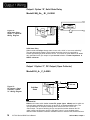
Output 1 Option “B”, Solid State Relay
ModeI# 98_A-_ B _0-0000
Figure 14 -
Solid State Relay,
Output 1, Option “B”
Wiring Diagram.
Solid State
Relay
Solid State Relay
Watlow's solid state relays change state at zero volts, which is *zero-cross switching.”
They are also optically isolated, which means the output circuitry is energized by
infrared light striking a photo-sensitive device. This results in virtual absence of electrically generated noise, pIus output to input electrical isolation. Off state impedance is
2OKohm minimum.
Output 1 Option “C”, DC Output (Open Collector)
Model# 98_A-_C_0-0000
Figure 15 DC Output 1 (Open
Collector), Option
72” Wiring Diagram.
u
71
.
+
3
.
.
.
.
.
.
.
-
-Q
,
DCLoad
Switched DC
Watlow’s solid state switch is a low current DC output (open collector) used to switch an
external power switching device such as an SSR or an electromechanical relay. The
input specifications of the power switching device must those listed for the SS
switch output. The power switching device must provide isolation between the SS
switch output and load power since the SS switch output is a non-isolated output.
Minimum load resistance is 5OOohms. Available current is minimum 9mA, 22mA maximum.
16
WATLOW Series 980/985 User’s Manual
Install and Wire, Chapter 2
Output 1 Option “D”, 6 Amp Mechanical Relay
Model#98_A-_D _0-0000
Figure 16 -
Mechanical
Relay
6 Amp mechanical
Relay, Output 1,
Optlon “D” Wlrlng
Diagram.
Mechanical Relay
The Electromechanical relay iS an electrical and mechanical d8vice with moving parts.
When power is applied to the relay solenoid, Contact closure is Created through movement of the “Common” Contact of the relay. Off state impedance is 2OK ohm minimum.
Output 1 Option “E”, 0-I0 VDC
Model# 98_A-_E _0-0000
Figure 17 -
0-10VDC, Output 1,
Optlon "E" Wiring
Diagram.
Process Output,
Proportional value determined by the Control to balance the sensor input and set point.
This value will fall between 0-10VDC depending on your process output type.
Install and Wire, Chapter 2
WATLOW Series 980/985 User’s Manual
17
Output 1 Option “F", 4-20mA
Model# 98_A-_F _0-0000
Figure 18 4-2OmA, Output 1,
Option "F" Wiring
Diagram.
Process Output
Proportional value determined by the control to balance the sensor input and set point.
This value will fall between 4-20mA depending on your process output type.
Output 1 Option “G”, O-20mA
Model# 98_A-_G _0-0000
Figure 19 0-20mA, Output 1,
Option “G” Wiring
Diagram.
Process Output
Proportional value determined by the control to balance the sensor input and set point.
This value will fall between 0-20mA depending on your process output type.
18
WATLOW Series 980/985 User’s Manual
Install and Wire, Chapter
2
Output 1 Option “H”, O-5VDC
Model# 98_A-_H _0-0000
Figure 20 O-5VDC, Output 1,
Option "H" Wiring
Diagram.
Process Output
Proportional value determined by the control to balance the sensor input and set point.
This value will fall between O-5VDC dependlng on your process output type.
Output 2 Option “B”, Solid State Relay
Model# 98_A- -
- B 0-0000
Figure 21 S.S. Relay,
Output 2, Option "B"
Wiring Diagram.
Solid State Relay
Watlow’s solid state relays change state at zero volts, which is zero-cross switching.”
They are also optically isolated, which means the output circuitry is energized by
infrared light striking a photo-sensitive device. This results in virtual absence of electrically generated noise, plus output to input electrical isolation. Off state impedance is
2 O K o h m s minimum.
Install and Wire, Chapter 2
WATLOW Series 980/985 Users Manual
19
Output 2 Option “C", DC Output (Open Collector)
Model# 98_A- __ C 0-0000
.
.
.
.
.
.
.
Figure 22 DC Output (Open
Collector), output 2
Option "C" Wiring
Diagram.
’
9
- 8 Heat, Cool
+ # or Alarm
Switched DC
Watlow’s solid state switch is a low current DC output (open collector) used to switch an
external power switching device such as a SSR or an electromechanical relay. The input
specifications of the power switching device must match those listed for the SS switch
output. The power switching device must provide isolation between the SS switch
output and load power since the SS switch output is a non-isolated output. Minimum
load resistance is 5 00 ohms. Available current is 9mA minimum and 22mA maximum.
Output 2 Option “D”, 6 Amp Mechanical Relay
Model# 98_A- - - D 0 - 0000
Figure 23 6 Amp Mechanical
Relay,
Output 2, Option "D"
Wiring Diagram.
Mechanical
Relay
Mechanical Relay
The electromechanical relay is an electrical and mechanical device with moving parts.
When power is applied to the relay solenoid, contact closure is created through movement of the “common” contact of the relay. Off state impedance is 20K ohms minimum.
20
WATLOWSeries 980/985 User’s Manual
InstaIl and Wire, Chapter 2
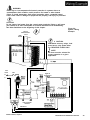
n
T
WARNING:
Install high or low temperature limit control protection in systems where an
overtemperature fault condition could present a fire hazard or other hazard.
Failure to install temperature limit control protection where a potential hazard
exists could result in damage to equipment and property, and injury to personnel.
0
0
1
CAUTION:
Do not jumper load power from the control power terminals. Doing so will cause
your control to be more susceptible to electrical interference from loadswitching.
See Noise Guidelines at the beginning of this chapter.
115 Volt
Control Power
L2 L1
Earth
A A
Ground
Fuse
Iif
01
1
Figure 24 System Wiring
Example
0
2 CAUTION:
With Watlow mercury relays, load
must have a unity power factor.
For RESISTIVE LOADS ONLY.
1 NOTE
All fuses must be selected for
proper protection in a given
application.
Load
Power
Fuse
Ll -
Ll L2
.t +
High Liiit
Control Power
120 YAC
140A-16XX-6000
HighLimit Control
*
*
Y!Ef
Heat
Load
flfi
I I
I 1
I ’
L2
Ll
Relay Contactor
coil Power
Limit Sensor
I
Process Sensor
Install and Wire, Chapter 2
I
WATLOW Series 980/985 Use's Manual
21
Chapter 3
How to Use the Keys and Displays
Series 980/985 Displays and Load LED’s
Upper Display
Red, 0.3” high LED, seven segment, three or four
digit display indicating either process actual temperature, the operating parameter values, or an
open sensor.
1 NOTE:
The Upper display
will always show
the process value
after 1 minute
without key
strokes.
Figure 25 Series 980/985
Displays
Lower Display /
Red 0.3” high LED, seven segment, three or
four digit, display indicating the set point,
output value, prompts for data in the upper
display, or error and alarm codes.
LOAD 1 When lit, this LED
tells you when
Output 1 is energized.
22
WATLOW Series 980/985 User’s Manual
Output 2 is energized or the alarm is
active.
Keys and Displays, Chapter 3
Series 980/985 Keys
Figure 27 Series 980/985 Keys
UP/DOWN keys
When pressed simultaneously for 3 seconds, the Setup Menu appears displaying
the LOC parameter. From the LOC parameter, press the UP/DOWN keys again
and the Calibration Menu appears.
MODE Key
Steps the control through the
Operating menu; also, in the
Auto mode, enters new data
selected less than 5 seconds
previously .
el
Increases the value
of the displayed
parameter. A light
touch increases the
value by one.
Holding the key
down increases the
display value at a
rapid rate. New
data is self entering
in 5 seconds.
/
DOWN Key
Decreases the value of the
displayed parameter. A light
touch decreases the value by
one. Holding the key down
decreases the displayed value
at a rapid rate. New data is
self entering in 5 seconds.
AUTO/MAN Key
Pressed once, it clears any
latched alarms. If the key is
pressed again within 5
seconds, the control toggles
between the Auto and Manual
mode. While in the Manual
mode, percent power is
always displayed in the lower
display.
Auto/Manual LED
Lit when the control is in Manual operation. Press the key twice to enter Auto
operation. A blinking Auto/Manual LED
indicates that pressing the Auto/Manual
key toggles between Auto and Manual.
After 5 seconds without pressing the
Auto/Manual key, the LED stops blinking,
and returns to its previous state.
Where To Go From -Here
Now that you know how to read the keys and displays, continue to Chapter 4 to
begin entering data and setting up your Series 980/985.
Keys and Displays, Chapter 3
WATLOW Series 980/985 User’s Manual
23
Chapter 4
1
NOTE:
While in the Setup
menu, all outputs
are OFF.
How To Setup The Series 9801985
Setting up the Series 980/985 is a simple process. First configure the 980/
985’s features to your application in the Setup Menu, and then enter values in
the Operating Menu. Both tasks use the MODE key to move through the
menus and the UP/DOWN keys to select data.
Entering the Setup Menu
The Setup Menu displays the parameters that configure the Series 980/985’s
features to your application.
To enter the Setup Menu, press the UP and DOWN keys simultaneously for 3
seconds. See Figure 27. The Lower display shows the LOC parameter, and
the Upper display shows its current level. All keys are inactive until you release
both keys. You can get to the LOC parameter from anywhere.
Figure 27 Entering the Setup
Menu.
Use the MODE key to cycle through the menu; use the UP/DOWN keys to
select Setup data. You may not see all the parameters in this menu, depending on the unit’s configuration and model number. After stepping through the
menu, you will return to the control set point parameter under the Operation
menu.
-l
@ Mode Key
Figure 28 The Setup Menu.
Prompt appears or not according
to control configuration.
an
NOTE:
When using a
process input such
as O-5VDC or
4-2OmA, the rL and
rH settings scale the
display to match the
measured range of
the process signal.
1 t Control Set Point
24 WATLOW
Series 980/985 User’s Manual
Setup, Chapter 4
Setup Parameters
At the top of the menu, the Series 980/985 displays the user level of operation
in the Upper display, and the LOC parameter in the Lower display. When
pressing the MODE key, the value of the next parameter appears in the Upper
display, and the parameter itself is in the Lower display.
Lock: Selects the level of operator lock-out. This parameter’s range is from
0 - 3. The default is 0. The levels of operator lock-out are defined as follows:
LOC 0: All operating parameters may be viewed or changed. Manual operation
is permitted.
LOC 1: The set point and actual are the only visible parameters, the set point
is adjustable in this level of lock-out. Manual operation is permitted.
LOC 2: The set point and actual are the only visible parameters, set point is
adjustable in this level of lock-out. Manual operation is not permitted.
Bumpless transfer is defeated.
LOC 3: The set point and actual are the only visible parameters, the set point is
not adjustable in this level of lock-out. Manual operation is not
permitted. Bumpless transfer is defeated.
Input: Selects the sensor input type. This parameter’s range is J, K, t, n, Pt2,
rtd, rt.d, 0-5, and 420. The default is Type “J”. Only those input types compatible with your unit appear. See the model number information for your type.
Remote Set Point: Enables the Series 980/985 to accept a remote set point
signal from another device. This parameter only appears on models 98XA2XXX-0000 or 98XA-3XXX-0000 and if In = Thermocouple or RTD input.
Range: OFF, 05,420 Default: OFF
Decimal: Selects the location of the decimal point for ail process related data.
The range is 0, 0.0, or 0.00. The default is 0. This parameter only appears if
the in parameter is 0-5 or 420.
Celsius _ Fahrenheit: Selects the units of measure for the control. The range
of this parameter is C or F. The default is F. This parameter only appears if the
In parameter is J, K, t, n, Pt2, rtd, or rt.d.
Range Low: Selects the low limit of the operating range. See the model
number and specification information in the Appendix for your range values. For
units with process input, it determines scaling of the remote set point input.
0.0VDC and 4mA input are equal to Range Low (rL) of your input type. Set point
is linearly scaled between rL and rH. See Chart 2 on Page 26.
Range High: Selects the high limit of the operating range. See the model
number and specification information in the Appendix for your range values. For
units with process input, it determines scaling of the remote set point input. The
5.OVDC and 2OmA input are equal to the Range High (rH) of your input type.
Set point is linearly scaled between rL and rH. See Chart 2 on Page 26.
Output 1: Selects the output action for the primary output. The range of this
parameter is Ht (Heating) or CL (Cooling). Default is Ht.
Output 2: Selects the output action for the secondary output. The range of this
parameter is Ht (Heating), CL (Cooling), AL (Alarm) or no (None). Default is AL.
l2-l
R H
CEI
Alarm Type: Selects the alarm type when Output 2 has been selected as an
alarm. The range of this parameter is Pr (Process Alarm) or dE (Deviation
Alarm). A process alarm is set at an absolute temperature to prevent over/
underrange. Deviation tracks your process set point. The default is Pr. This
only appears if the Ot2 parameter is AL.
SetupChapter4
WATLOW Series 980/985 User’s Manual
25
Latching: Selects whether the output is latching or non-latching when Output 2
is an alarm. Latching alarms must be cleared before the alarm output will reset.
Non-latching automatically resets the alarm output when the condition clears.
The range is LAt or nLA, default is nLA. This only appears if the Ot2 = AL.
Silencing: Selects alarms silencing (alarm inhibit). Appears only when
ALt = dE. If LAt, press the Auto/Man key to reset the alarm output. If nLA, alarm
automatically resets 5 seconds after power is applied.
RTD: Selects the RTD calibration curve. JIS = 0.003916 / PC
DIN =0.003850 / °C.
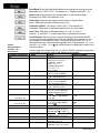
Chart 1Setup Menu
Prompts and
Descriptions.
Use this page as a master copy for configuring your Series 980/elects the low
limit of the Operating range See the model number and specification informa-
Setup Parameters
Value
Factory Default
Range
LOC
0-3
0
In
J, K (appears as H), t, n,
Pt2, rtd, rt.d, 0-5,4-20
Dependent on model number.
J
rSP
OFF, O-5,420
OFF
DEC
0, 0.0, or 0.00
0
Dependent on input type.
C-F
C or F
Will not appear if In = 0-5 or 420.
F
rL
rLtorH
Input selection dependent.
rH
rH to rL
Input selection dependent.
Otl
Ht or CL
Ht
ot2
Ht. CL, AL or no
AL
ALt
Pr or dE
Dependent on Ot2 = AL.
Pr
LAt
LAt or nLA
Dependent on Ot2 =AL.
nLA
SIL
OFF or On
Appears if Ot2=AL&ALt=dE.
OFF
rtd
JIS or din
Appears if In = rtd or rt.d.
JIS
Input Type
Chart 2Input Ranges.
J
I
K
1
n
I
Pt2
rtd
(1°)
Sensor Range Low
Sensor Range High
32°F/0°C
32°F/0°C
999*F/750°C (3 digit)
1 382°F/750°C (4 digit)
-328°F/-200°C
2282°F/1 250°C
2543°F/l395°C
-328°F/-200°C
111 2°F/600°C
-99.9°F/-99.9°C
I
0-5 (VDC) 1
-5.00/-50.0/-500
26 WATLOW Series 980/985 User’s Manual
I
32°F/O°C
rt.d (0.1’) 1
I
2282°F/1250°C
32°F/0°C
I
420 (mA)
1
1 .-5.00/-50.0/-500 1
I
I
392.0°F/200.0°C
I
I
35.00/350.0/3500
I
35.00/350.0/3500
1
Setup, Chapter4
m Mode Key
J NOTE:
The Upper display
will always show the
process value after 1
minute without key
strokes.
+ Control Set Point
1 g.f$fygj [!I=. Prompt appears or not according to control configuration.
Figure 29 The Operation Menu.
Operation Parameters
Set Point 2: Sets the operating set point for Output 2 when control mode is Ht/
Ht or CL/CL. SP2 only appears when Ot1 and 0t2 are the same, and functions
as an ON/OFF control.
Proportional Band: Set the proportional bandwidth for each Output, adjustable
from 0° to 999°F or 0 to 555°C for ranges displayed in whole degrees, and 0 to
99.9°F or 0 to 55.5°C for ranges displayed in 0.1°. If set at Pb = 0, the Series
9801985 functions as a simple ON/OFF control with a 3°F or 1.7°C switching
differential for ranges displayed in whole degrees, and 0.3°F or 0.17°C for
ranges displayed in 0.1°. The default is 25°F/13°C.
If the input type is 0-5VDC or 4-20mA, the range of Pb1 is 0-999, 0-99.9 or O9.99 (determined by the value of DEC). The switching differential is 0.03, 0.3 or
3 units. Pb2 default is 0. Pb2 only appears with Ht/CL or CL/Ht operation.
Reset: Enter Reset for Output 1 or 2, adjustable from 0.00 to 9.99 rpts/min. A
value of 2.00 rpts/min. corresponds to an integral time constant of 30 seconds.
Selecting 0.00 = no integral action. rE2 only appears with Ht/CL or CL/Ht
operation. rA X will not appear if Pb X = 0 respectively.
Rate: Adjust Rate function for Output 1 or 2, from 0.00 to 9.99 minutes maximum. Selecting 0.00 = no derivative action. rA2 will only appear with Ht/CL or
CL/Ht operation. rA X will not appear if Pb X = 0 respectively.
Cycle Time: Enter the Cycle Time for each Output, adjustable from 1 to 60
seconds. The default will be 5 seconds. Ct1 will not appear if Output 1 is 4-20.
CT2 only appears with Ht/CL or CL/Ht operation..
Setup, Chapter 4
WATLOW Series 980/985 User’s Manual
27
Dead Band: Enter the Dead Band between the heating and cooling functions
adjustable from ± 99°F/± 55°C. The default is 0°. Appears when Ot2 = CL.
Alarm Low: Represents the low process alarm or low deviation alarm.
Displayed only when 0t2 parameter is AL.
Alarm High: Represents the high process alarm or high deviation
alarm. Displayed only when Ot2 parameter is AL.
Calibration Offset. The range is ±99°F/±55°C. The default is 0°.
Calibration Offset adds or subtracts degrees from the input signal.
Chart 3 Operation Menu
Prompts and
Descriptions.
Operation Parameters
Auto-Tune. The range of this parameter is 0-3, off = 0, slow = 1,
medium = 2, and fast = 3. A value other than 0 initiates the auto-tune.
Local-Remote: Selects a local or remote set point for the Series 980/985.
Local set point is adjustable directly from the 980/985, while remote can only
be changed from an external device. The signal must be within O-5V or 420mA process input. This parameter appears if the LOC parameter = 0, 1 or 2,
and rSP = 0-5 or 420. If L-r = r, the remote set point is displayed in place of the
internal set point.
Use this page as a master copy for your Series 980/985. Operation Parameters.
Do not enter any values here: make photocopies instead.
Value
SP2
Pbl
Pb2
rE1
rE2
rA1
rA2
AL0 -
Deviation dE
AHI -
Process Pr
Deviation dE
Process Pr
Ctl
Ct2
db
CAL
AUt
L-r
2 8 WATLOW Series 980/985 User’s Manual
Range
rL to rH
0 to 999°F/0 to 555°C or
0 to 99.9°F/0 to 55.5°C
0=ON/OFF control
with 3°F or 1.7°C
switching differential.
0.3°F or 0.17°C
for 0.10 units.
Same as Pb1 . Only appears if
Ht/CL or CL/Ht operation.
0.00 to 9.99 repeats/min.
0.00 = No Reset Action
Same as rE1. Only appears if
Ht/CL or CL/Ht operation.
Will not appear if Pb2 = 0.
0.00 to 9.99 min.
0.00 = No Rate Action
Same as rA1. Only appears
if Ht/CL or CL/Ht operation.
Will not appear if Pb2 = 0.
-99° to O° (3 digit display)
-999° to 0° (4 digit display)
rL to AH1
0 ° to 99° (3 digit display)
0 ° to 999° (4 digit display)
AL0 to rH
1 to 60 seconds
1 to 60 seconds
Appears if Ht/CL or CL/Ht
Will not appear if PB2 = 0
±99°F/±55°C. ’
Appears if Ht/CL or CL/Ht
±99°F/±55°C
0-3
Appears if Ot1 = Ht.
L or r.
Appears if rSP = 0-5 or 420.
Factory Default
Same as primary set point.
25°F/l3°C (3 or 4 digit)
0°F/0°C (3 or 4 digit)
0.00 repeats/min.
0.00 repeats/min.
0.00 min.
0.00 min.
-99°
-999°
rL
99°
999°
rH
5 seconds
5 seconds
0
0
0
Setup, Chapter 4
1
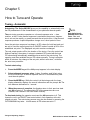
Chapter 5
How to Tune and Operate
Tuning - Automatic
Auto-tuning: The Series 9801985 gives you the capability to automatically tune
the PlD parameters to fit the characteristics of your particular thermal system.
The auto-tuning procedure operates on a thermal response value - slow,
medium, or fast. A slow thermal response is used when the process temperature is not met too rapidly, or greatly exceeds the set point value. A fast thermal
response produces a rapid temperature change over a short period of time.
J NOTE:
Auto-tuning is only
possible in the heat
mode. The cool
output remains off.
Once the auto-tune sequence has begun, all PID values for both heat and cool
are set to 0 and the control goes into an ON/OFF mode of control at 90% of the
established set point. The displayed set point remains unchanged.
The cool output remains off for the duration of the tuning. Once the control has
finished “learning” the system, it returns to standard PID control with the heat
PID values being automatically established as a result of the auto-tuning. The
operator must then establish the cool PID values manually. Tuning is complete
within 40 minutes. Any change of the set point, while in auto-tune, re-initiates
the auto-tune procedure.
To start auto-tuning:
1.
Press the MODE key until the AUt prompt appears in the data display.
2.
Select a thermal response value, 1=slow, 2=medium, and 3=fast, using
the UP/DOWN keys. A thermal response value of 2 will satisfactorily tune
most thermal systems.
3.
Press the MODE key. While the control is in the tuning mode, the lower
display alternately displays the normal information and the prompt At. The
time between alternations is 1 second.
4.
When the process is complete, the displays return to their previous state
and AUt reverts to 0. The appropriate PID tuning parameters are now
installed, and retained in the non-volatile memory.
To abort auto-tuning, the operator must reset the AUt parameter to 0. This
leaves the unit in an ON/OFF heat control state in Auto operation at the displayed set point. The auto-tuning process may also be aborted by pressing the
AUTO/MANUAL key twice. In both cases, all PID values are set to 0.
Tuning and Operating, Chapter 5
WATLOW Series 980/985 User's Manual
29
Tuning - Manual
For optimum control performance, tune the Series 985 to the thermal system
The tuning settings here are meant for a broad spectrum of applications; your
system may have somewhat different requirements.
1. Apply power to the Series 965 and enter a set point. Begin with these
Operation Parameters: Pbl = 1, rE1 = 0.00, rA1 = 0.00, Ct1 = 5, CAL = 0,
AUt= 0.
2. ProportionaI Band Adjustment (Output 1): Gradually increase Pb1 until
the Upper display temperature stabilizes to a constant value. The process
temperature will not be right on Set point because the initial reset value is
0.00 repeats per minute.
PB1 = 0; rE1 and rA1 are inoperative, and
the 985 functions as a simple ON/OFF control with a 3°F or 1.7°C switching
differential.)
3. Reset Adjustment: Gradually increase rE1 until the upper display temperature begins to oscillate or “hunt”. Then slowly decrease rE1 until the
Upper display stabilizes again near set point. NOTE: This is a slow procedure, taking from minutes to hours to obtain optimum value.
4. Cycle Time Adjustment: Set Ct1 as required. Optimum system control is
sometimes achieved with faster cycle times. However, if a mechanical
contactor or solenoid is switching power to the load, a longer cycle time may
be desirable to minimize wear on the mechanical components. Experiment
until the cycle time is consistent with the quality of control you want.
5. Rate Adjustment: lncrease rA1 to 1.00 min. Then raise set point by 20° to
30°F, or 11° to 17°C Observe the system’s approach to set point. If the
load temperature overshoots set point, increase rA1 to 2.00 minutes.
Then raise set point by 20 to 30°F, or 11 to 17°C and watch the approach to
the new set point. If rA1 is advanced too far, approach to the set point will
be very sluggish. Repeat as necessary until the system rises to the new set
point without overshooting or approaching the set point too slowly.
6. Calibration Offset Adjustment: You may want your system to control to a
temperature other than the value coming from the input sensor. If so,
measure the difference between that temperature, perhaps at another point
in the system, and the process value showing in the Upper display. Then
enter the amount of CAL offset you want. Calibration offset adds or subtracts degrees from the value of the input signal.
Manual and Automatic Operation
To change from manual to auto operation, press the AUTO/MAN key twice.
Manual operation provides direct (time proportioned % power) control of the
outputs from -100% to 100%. A negative output value is allowed only with a Cl
(Cool) selection on either Otl or 0t2. Automatic operation provides closed loop
ON/OFF or PID control. When the operation transfers from a closed loop to an
open loop, the 985 retains the power level from the closed loop control. When
returning to the closed loop control, the previous set point temperature is
restored.
30
WATLOW series 98O/985 User’s Manual
Tuning and Operating, Chapter 5
Indication of Auto/Manual operation is the LED located on the AUTO/MAN key.
When the LED is ON, the control is in the Manual operation, an alarm condition
is present, and the output de-energizes. When the LED is OFF, the control is in
AUTO operation and the alarm is energized. When the LED flashes, press the
key again within five seconds to complete the change in operation. If the sensor
is open and LOC = 0 or 1, the Series 985 switches to Manual operation (time
proportioned % power), if the output was stable before the break occurred.
When transferring from auto to manual operation, the control output(s) will not
change (“bumpless,” smooth transition). When transferring from manual to
automatic operation, the control output(s) may change significantly. In manual,
the output value (% power) appears in the lower display. In automatic operation,
the set point appears.
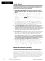
Using Alarms
The Series 985 has two alarms types, Process or Deviation. A Process alarm
sets an absolute temperature when the process exceeds that absolute temperature limit. The Process alarm points may be independently set high, low,
or high/low.
A Deviation alarm alerts the operator when the process strays too far from set
point. The operator can enter independent high and low alarm settings. The
reference for the deviation alarm is the set point. Any change in set point
causes a corresponding shift in the deviation alarm. Example: If your set point
is lOO°F, and you have a deviation alarm set at ±7°F as the high limit, and -5°F
as the low limit, the high alarm will trip at 107°F, and the low alarm at 95°F. If
you change the set point to 130°F, the alarms will follow the set point and trip at
137°F and 125°F.
Figure 31 Alarm Display
Examples
Alarm Silencing for alarm output A1 is available with the deviation alarm. This
overrides alarm A1 during power up. The non-latching mode automatically
enables alarm output A1 on initial power up. In the latching mode, the operator
must manually disable the alarm by pressing the AUTO/MAN key once. In both
cases alarm silencing disables the A1 alarm output relay, but the A1 LED
displays the alarm condition until the process value is within the “safe” region of
the deviation alarm band. Once the process value crosses into the “safe”
region, both a latching or a non-latching alarm is ready. Any future deviation
outside this safe band triggers an alarm.
Both Process and Deviation alarms can be latching or non-latching. The
operator must manually reset a latching alarm before the alarm will reset. The
operator must also remove the condition that created the alarm. When the
operator removes the condition causing the alarm, a non-latching alarm automatically resets the alarm output.
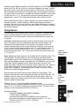
Flashing ‘LO” or “HI” in the lower display indicates an alarm.
The Lower display alternately displays information from the current parameter
and the “LO” or “HI” alarm message at one second intervals. The alarm output
(Output 2) is de-energized and the LOAD 2 LED is lit.
Press once Clear
a latched
and
corrected
alarm.
To clear an alarm...
l
The alarm condition must first be corrected...
• If the alarm is latching...
Clear manually; press the AUTO/MAN key once as soon as
the process temperature is inside the alarm limit by 3°F/l.7°C for 1°
RTD units, and 0.3°F/0.17°C for 0.1° RTD units.
Tuning and Operating, Chapter 5
WATLOW Series 980/985 User’s Manual
31
•If the alarm is non-latching...
The alarm will clear itself automatically as soon as the process
temperature is inside the alarm limit by 3°F/l.7°C for 1° RTD units, or
0.3°F/0.17°C for 0.1° RTD units.
A
1
CAUTION:
An alarm display will be masked by an error condition or when the
control is in the Calibration or Set Up Menus.
l
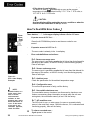
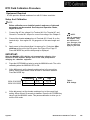
How To Deal With Error Codes J’
Press
~ twiceRead
error
Three dashes, “- - -", in the upper display indicate a Series 985 error.
l
If operator access is LOC 0 or 1 . . .
Press the AUTO/MAN key twice to see the error code for one
second.
l
•
If operator access is LOC 2 or 3...
l
•
The error code is already in the lowerdisplay.
Error code definitions and actions...
Er 1- Sensor overrange error
The sensor input is generating a value that is higher than that allowed for
the range of this sensor, or the A/D circuitry is not functioning properly.
Enter a valid input.
Er 2 - Sensor underrange error
The sensor input is generating a value that is lower than that allowed for
the range of this sensor, or the A/D circuitry is not functioning properly.
Enter a valid input.
Figure 32 Error Code Display
Examples
J
Er 3 - Ambient error
Check the specification for the ambient temperature range.
Er 4 - Configuration error
The unit’s microprocessor is faulty; call the factory.
NOTE:
Electrical noise or a
noise event, vibration or excess
environmental
moisture or temperature may cause
Series 985 errors to
occur. If the cause
of an error is not
otherwise apparent,
check for these.
Er 5 - Non volatile checksum error
The nonvolatile memory checksum has discovered a checksum error.
Unless a momentary power interruption occurred while the unit was
storing data, the nonvolatile memory is bad. Call the factory.
Er 7 - A/D overflow error
The A/D circuit is over- or under-range. An open or reversed polarity
sensor is the most likely cause. Check the sensor; if it is connected and
functioning properly, then call the factory.
To clear a corrected error...
l Cycle power to the control.
32
WATLOW Series 980/985 User’s Manual
Tuning and Operating, Chapter 5
Er 1, 2, 3 & 7 Errors - Control Outputs May Be ON
If operator access is LOC 0 or 1 . . .
. ..and the control was in AUTO operation when the error occurred, it will
go into MANUAL (% power) operation. If the output power is less than
70%±5% change within the last two minutes, the 985 will switch into
Manual operation at the last Automatic power level. If the control was in
MANUAL operation, it will remain there. (You must press the AUTO/
MAN key twice to see the error code.) The alarm output (if present) will
be in its alarm state (LED lit). The Upper display will read “- - -“. The
Lower display will indicate the error code.
If the control was operating with stable output values when the error
occurred, it will continue to operate at those levels on a % power basis.
If output values were not stable, the control outputs will go to 0% power
(OFF).
.
If operator access is LOC 2 or 3. . .
The control will remain in AUTO operation. The control outputs will go
OFF. The AUTO/MAN and MODE keys are disabled. The UP/DOWN
keys may be used together to enter the Set Up Menu. The alarm output
(if present) will be in its alarm state (LED lit). The Upper display will read
” - - -“. The Lower display will indicate the error code.
l
To clear a corrected error...
l
Cycle power to the control.
Er 4 & 5 Errors - Control Outputs Will Be OFF
Error codes Er 4 and Er 5 will result in these conditions:
The control is in AUTO operation with both Outputs OFF.
The alarm output (Output 2), if present, is in its alarm state (de-energized with the LED lit).
The Upper display will indicate the process value#.
The Lower display will indicate the error code.
All Keys are inactive.
All Set Up Menu parameters are reset to default values. Calibration
values 4AO and 2AO are set to default values. All other Calibration
Menu values remain unchanged.
These conditions will occur regardless of the value of LOC, or the presence of the Set Up or Calibration Menus.
To clear a corrected error. . .
l
Cycle power to the control.
l
Recalibrate the 4-20mA output, if applicable (see the unit’s model #).
Tuning and Operating, Chapter 5
WATLOW Series 9801985 User’s Manual
33
Appendix
Control Mode
•
l
l
Single set point, non-ramping.
Single input, dual outputs.
Control outputs: User selectable as: Heat, Heat/Heat, Heat/Cool, Cool,
Cool/Cool, Heat/Alarm, Cool/Alarm
Outputs independent, or related via deadband for Heat/Cool.
ON/OFF: 3°F or 1.7°C switching hysteresis or 0.3°F or 0.l7°C for
0.10 Units .
PID parameters:
Proportional band: 0 to 999°F/0 to 555°C(3 digit only)
0 to 999°F/0 to 555°C or 0 to 99.9°F/0 to 55.5°C (3 or 4 digit)
Reset: 0.00 to 9.99 repeats per minute.
Rate: 0.00 to 9.99 minutes.
Cycle time: 1 to 60 seconds.
Deadband: ±99°F, ±99 units or ±55°C
±9.9°F, ±9.9 units or ±5.5°C for 0.1 decimal units)
l
l
l
l
Operator Interface
l
l
l
l
Membrane front panel.
Three or four digit 0.3” (8mm) LED diiplays.
MODE, AUTO/MANUAL, UP, and DOWN keys.
Dual digital displays.
Input
Thermocouple, RTD, and electrical process input.
Automatic cold junction compensation for thermocouple.
RTD input 2 or 3 wire, platinum, 100 ohm @ 0°C user selectable, calibrate
to JIS curve #3916 (0.003916(0.003916ohm/ohm/°C or DIN curve #3850(0.003850ohm/ohm°C
Sensor break protection de-energizes control output to protect system or
selectable bumpless transfer to manual operation.
Grounded or ungrounded sensors.
°F/°C or process variable units are user selectable.
Operating ranges user selectable.
32 to 999°F or
0 to 750°C (3
32 to 1382°F or
0 to 750°C (4
K t/c:
- 3 2 8 t o 2282°F or -200 to 1250°C
T t/c:
-328 to 662°F or -200 to 350°C
N t/c:
32 to 2282°F or
0 t o 1250°C
PT 2 (Platinel2) 32 to 2543°F or
0 t o 1395°C
1° RTD:
-328 to 1112°F or -200 to 600°C
0.1° RTD:
-99.9 to 392.0°F or -99.9 to 200.0°C
0-5VDC:
-500 to 3500 units
4-20mA:
-500 to 3500 units
J t/c:
34
WATLOW Series 980/985 User’s Manual
Digit)
Digit)
Appendix
Primary Output (Heating or Cooling)
Solid state relay, 0.5A @ 24VAC minimum, 253VAC maximum, optoisolated, zero cross switching.
Electromechanical relay, Form C, 6A @ 115/230VAC, 6A @ 28VDC,
1/8 hp. @ 115VAC 125VA @ 115VAC. Warranted to 100,000 cycles.
Open collector, switched DC signal provides a minimum turn ON voltage of
3VDC into a minimum 500 ohm load, maximum ON voltage not greater than
32VDC into an infinite load.
4-20mA reverse acting into a 600 ohm maximum load.
l
l
l
l
Secondary Output (Heat, Cool or Alarm)
l
.
l
Solid state relay, 0.5A @ 24VAC minimum, 253VAC maximum, optoisolated, zero cross switching.
Electromechanical relay, Form A, 6A @ 115/230VAC, 6A @ 28VDC,
1/8 hp. @ 115VAC, 125VA @ 115VAC. Warranted to 100,000 cycles.
Open collector, switched DC signal provides a minimum turn ON voltage of
3VDC into a minimum 500 ohm load; maximum ON voltage not greater than
32VDC into an infinite load.
Accuracy
Calibration Accuracy: ± 0.1% of span, ± 1 LSD,
77°F ± 5°F (25°C ±3°C) ambient & rated line voltage ± 10%.
Accuracy Span: 1000°F or 540°C minimum.
Temperature Stability: 0.1 °F/°F (0.1 °C/°C) change in ambient.
Voltage Stability: ± 0.01% of span per percent of rated line voltage.
l
l
l
l
Agency Approvals
UL recognized, File #E43684, UL873
CSA file #LR30586
l
l
Terminals
#6 compression type screw terminals
l
Power
.
.
l
115/230VAC +1 0%, -15%, 50/60Hz, ± 5%
10VA maximum
Data retention upon power failure via nonvolatile memory
Operating Environment
l
l
32 to 1 30°F/0 to 55°C.
0 to 9O% RH, non-condensing.
Dimensions
(985 orientation) For 980 units, switch height and width measurements.
l
l
l
l
l
Height:
Width:
Overall depth:
Behind panel depth:
Weight:
Appendix
3.8 in.
1.9 in.
6.3 in.
6.0 in.
0.9 lb.
(96.5 mm)
(48.0 mm)
(160.5 mm)
(152.5 mm)
(0.4 kg)
WATLOW Series 980/985 User’s Manual
35
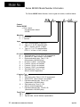
Series 980/985 Model Number Information
The Series 980/985 Model Number, listed on your unit sticker, is defined below.
,918
‘
Control
Series 980/985
= Dual output,
microprocessor-based
I/8 DIN
Mounting
0 = Horizontal
5 = Vertical
Input
1
2
3
,
= Type J thermocouple (3 digit only)
= Type J, K, T, N, PT 2 thermocouple;
RTD 1°, 420mA, 0-5VDC (4 digit)
= Type J, K, T, N, PT 2 thermocouple;
RTD 0.1°, 4-20mA, 0-5VDC (4 digit)
#1 output
B = Solid state relay, Form A, 0.5A, RC suppression
c = Switched DC, open collector, non-isolated
D = Electromechanical relay, Form C, 6A
(Warranted to 100,000 cycles)
E = Process, 0-10VDC, non-isolated
F = Process, 4-20mA, non-isolated
G = Process, 0-20mA, non-isolated
H = Process, 0-5VDC, non-isolated
K = Solid state relay, Form A, 0.5A,
without contact suppression
#2 output Type
A = None
B = Solid state relay, Form A, 0.5A, RC suppressed
c = Switched DC, open collector, non-isolated
D = Electromechanical relay, Form A, 6A
(Warranted to 100,000 cycles)
K = Solid state relay, Form A, 0.5A
without contact suppression
L = Electromechanical relay, Form B, 6A
(Warranted to 100,000 cycles)
Front Panel
00 = Standard
xx = Special label, consult Watlow representative
36
WATLOW Series 980/985 User’s Manual
Appendix
Calibration Menu
n?
l
In the Calibration Menu, various input signals must be supplied in order for the
control to go through its auto calibration. The calibration menu can only be
entered from the LOC parameter in the Setup menu. Press the UP/DOWN
keys simultaneously for 3 seconds (± 1 second). The CAL parameter appears.
CAUTION:
Incorrect calibration
will affect the
accuracy and should
only be attempted
with proper equipment and by qualified personnel.
Figure 33 Entering the
Calibration Menu.
1
Any inadvertent change in displayed data when pressing UP & DOWN, is
ignored. At the CAL parameter, press the AUTO/MANUAL key twice to enter
the MANUAL mode. Calibration values are not retained unless in MANUAL
mode.
Upon entering the calibration menu, the top display window indicates CAL and
keys are inactive until all keys are released. The upper display continues to
indicate CAL (with the exception of calibration of the 4-20mA output) while the
operator walks through the entire calibration parameter list. While calibrating
the 4-20mA output, the upper display contains a numeric value that is slewed
up or down until the output value is correct. The control uses the lower display
to prompt the user as to what the input should be.
NOTE:
Calibration values
are not retained
unless you are In the
MANUAL mode.
J3
NOTE:
While in the Calibratlon Menu, all
outputs are OFF,
except the 4-20mA
output.
Once the input has been properly established and maintained for at least 10
seconds, the MODE key may then be used to display the next prompt. After
the final input is established, another press of the MODE key returns the unit to
the configuration menu at the top of the parameter list.
Cal Restore
If you make a mistake in calibrating your control, the rSt prompt at the end of
the calibration menu restores the original factory calibration settings. Simply
select yes and press the MODE key. The original factory calibration values are
restored. Figure 34 on the next pages shows the calibration prompt.
Appendix
WATLOW Series 980l985 User’s Manual
37
tcL
Thermocouple, low end uncompensated. 0 mV
tcH
Thermocouple, high end uncompensated. 50mV
Thermocouple compensated value reference.
RTD low end resistance, see Table 2 on Page 39.
RTD high end resistance, see Table 2 on Page 39.
Figure 34 The Calibration
Menu.
t
Process input. 0V
Process input. 5V
Process input. 4mA
A
4A0
Process input. 20mA
t Process output. 4mA
Process output. 20mA
Restore factory calibration values. See Page 37.
Factory use only.
Factory use only.
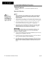
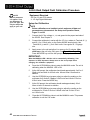
Thermocouple Field Calibration Procedure
Equipment Required
l
l
Type “J” Reference Compensator with reference junction at 320F/0°C, or
Type “J” Thermocouple Calibrator set at 320F/0°C.
Precision millivolt source, 0-50mV min. range, 0.01 mV resolution
k NOTE
Setup And Calibration p
Before calibration
on an installed
control, make sure
all data and
parameters are
documented. See
Setup and Operation
Charts, Pages 26
and 28.
1.
Connect the AC line voltage Ll to Terminal #4, L2 to Terminal #7, and
Ground to Terminal #8. Jumper for correct line voltage. See Chapter 2.
2.
Connect the millivolt source to Terminal #18 Negative and Terminal #20
Positive on the 980/985 terminal strip. Use regular 20 - 24 gauge wire.
3.
Apply power to the unit and allow it to warm up for 15 minutes. After
warm-up put the unit in the CAL menu. See Figure 33 on Page 37.
IMPORTANT:
When the MANUAL LED is ON the unit is automatically calibrating. Your
sequence is VERY important. Always move to the next prompt before
changing the calibration equipment.
J3 NOTE:
Not all parameters
will appear. They
are dependent on
your unit type. Use
only the steps that
apply to your unit.
38
4.
Press the AUTO/MAN key twice to enter the MANUAL mode. The unit is
calibrating when the MANUAL LED is ON.
5.
At the “tcL” prompt, enter 0.00 millivolts from the millivolt source to the
control. Allow at least 10 seconds to stabilize. Press the MODE key.
6.
At the “tcH” prompt, enter 50.00 millivolts from the millivolt source to the
9801985. Allow at least 10 seconds to stabilize. Press the MODE key.
7.
At the “tc” prompt, disconnect the millivolt source, and connect the
reference compensator or T/C calibrator to Terminal #18 Negative, and
Terminal #20 Positive on the Series 980/985 terminal strip. Allow 10
seconds for the control to stabilize. Press the AUTO/MAN key twice to
exit the MANUAL mode. This pauses calibration to allow you to exit the
CAL mode.
WATLOW Series 980l985 User’s Manual
Appendix
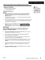
RTD Field Calibration Procedure
Equipment Required
l
1K ohm precision decade resistance box with 0.01 ohms resolution.
Setup And Calibration
ar NOTE
Before calibration on an installed control, make sure all data and
parameters are documented. See Setup and Operation Charts,
Pages 26 and 28.
1.
Connect the AC line voltage L1 to Terminal #4, L2 to Terminal #7, and
Ground to Terminal #8. Jumper for correct line voltage. See Chapter 2.
2.
Connect the decade resistance box to Terminal #12,13 and 14 on the
terminal strip. Use regular 20 - 24 gauge wire of the same length and
type.
3.
Apply power to the unit and allow it to warm up for 15 minutes. After
warm-up put the unit in the CAL menu. See Figure 33 on Page 37.
Press the MODE key until the rL0 prompt is displayed.
A NOTE:
Not all parameters
will appear. They
are dependent on
your unit type. Use
only the steps that
apply to your unit.
IMPORTANT:
When the MANUAL LED is ON the unit is automatlcally calibrating. Your
sequence is VERY important. Always move to the next prompt before
changing the calibration equipment.
4.
Press the AUTO/MAN key twice to enter the MANUAL mode. The unit is
calibrating when the MANUAL LED is ON.
5.
At the rL0 prompt, set the decade resistance box to the correct low
setting- See the table below. Allow at least 10 seconds to stabilize.
Press the MODE key.
985A-2XX0-0X00
985A-3XX0-0X00
6.
1
Calibration
1 Low 1
I
1
I
I
*
1°
0.1 °
17.31
59.57
High
I
i
317.33
177.13
Table 2RTD Settings.
At the rHI prompt, set the decade resistance box to the correct high
setting. Allow at least 10 seconds to stabilize. Press the AUTO/MAN key
twice to exit the MANUAL mode. This pauses calibration to allow you to
exit the CAL mode.
Appendix
WATLOW Series 980/985 User’s Manual
39
0 - 5 Volt Field Calibration Procedure
Equipment Required
l
Precision voltage source 0-5 volt minimum range with 0.001 volt
resolution.
Setup And Calibration
J-3 NOTE:
Not all parameters
will appear. They
are dependent on
your unit type. Use
only the steps that
apply to your unit.
aI NOTE
Before calibration on an installed control, make sure all data and
parameters are documented. See Setup and Operation Charts,
Pages 26 and 28.
1.
Connect the AC line voltage Ll to Terminal #14, L2 to Terminal #7, and
Ground to Terminal #8. Jumper for correct line voltage. See Chapter 2.
2.
Connect the voltage/current source to Terminal #15 and #17 on the
Series 980/985 terminal strip. Use regular 20 - 24 gauge wire.
3.
Apply power to the unit and allow it to warm up for 15 minutes. After
warm-up put the unit in the CAL menu. See Figure 33 on Page 37.
Press the MODE key until the OU prompt is displayed.
IIMPORTANT:
When the MANUAL LED Is ON the unit is automatically calibrating. Your
sequence is VERY important. Always move to the next prompt before
changing the calibration equipment.
40
4.
Press the AUTO/MAN key twice to enter the MANUAL mode. The unit is
calibrating when the MANUAL LED is ON.
5.
At the OU prompt, set the voltage/current source to 0.00 volts. Allow at
least 10 seconds to stabilize. Press the MODE key.
6.
At the 5U prompt, set the voltage/current source to 5.00 volts. Allow at
least 10 seconds to stabilize. Press the AUTO/MAN key twice to exit the
MANUAL mode. This pauses calibration to allow you to exit the CAL
mode.
WATLOW Series 980/985 User’s Manual
Appendix
4-20mA Input Field Calibration Procedure
Equipment Required
l
Precision current source 0-20mA minimum range with 0.01 mA
resolution.
Setup And Calibration
J
1 NOTE
Before calibration on an installed control, make sure all data and
parameters are documented. See Setup and Operation Charts,
Pages 26 and 26.
1.
Connect the AC line voltage Ll to Terminal # 4 , L2 to Terminal #7, and
Ground to Terminal #8. Jumper for correct line voltage. See Chapter 2.
2.
Connect the voltage/current source to Terminal #15 and #17. Jumper
Terminal #16 to #1 7 on the Series 980/985 terminal strip. Use regular
20 - 24 gauge wire.
.
Apply power to the unit and allow it to warm up for 15
15 minutes. After
warm-up put the unit in the CAL menu. See Figure 33 on Page 37.
Press, the MODE key until the 4A prompt is displayed.
NOTE:
Not all parameters
will appear. They
are dependent on
your unit type. Use
only the steps that
apply to your unit.
IMPORTANT:
When the MANUAL LED is ON the-unit is automatlcally calibratlng. Your
sequence is VERY Important. Always move to the next prompt before
changing the calibration equlpment.
4.
Press the AUTO/MAN key twice to enter the MANUAL mode. The unit is
calibrating when the MANUAL LED is ON.
5.
At the 4A prompt, set the mA source to 4.00mA. Allow at least 10
seconds to stabilize. Press the MODE key.
6.
At the 20A prompt, set the voltage/current source to 20.00mA. Allow at
least 10 seconds to stabilize. Press the AUTO/MAN key twice to exit the
MANUAL mode. This pauses calibration to allow you to exit the CAL
mode.
Appendix
WATLOW Series 980/985 User’s Manual
41
0-20/4-20mA Output Field Calibration Procedure
J3 NOTE
Not all
parameters
will appear. They
are dependent on
your unit type. Use
only the steps that
apply to your unit.
Equipment Required
l
l
470 ohm 1/2 watt 10% resistor.
4 - 1/2 digit Digital Multimeter.
Setup And Calibration
J NOTE
Before calibration on an installed control, make sure all data and
parameters are documented. See Setup and Operation Charts,
Pages 26 and 28.
1.
Connect the AC line voltage Ll , L2, and ground to the proper terminals of
the 980/985. See Chapter 2.
2.
Connect the multimeter in series with the 470 ohm resistor to Terminal #1 (+)
and #3 (-) for 0-20mA units, on the Series 980/985 terminal strip. Use
Terminal #I (+) and #2 (-) for 4-20mA units. Use regular 20 - 24 gauge
wire.
3.
Apply power to the unit and allow it to warm up for 15 minutes. After
warm-up put the unit in the CAL menu. See Figure 33 on Page 37.
Press the MODE key until the 4A0 prompt is displayed.
IMPORTANT:
When the MANUAL LED 's ON the unit is automatically calibrating. Your
sequence is VERY important. Always move to the next prompt before
changing the calibration equipment.
42
4.
Press the AUTO/MAN key twice to enter the MANUAL mode. The unit is
calibrating when the MANUAL LED is ON.
5.
At the 4A0 prompt, the multimeter should read approximately 0mA for 020mA units and 4mA for 4-20mA units. Allow at least 10 seconds to
stabilize.
6.
Use the UP/DOWN keys (reverse acting) to adjust the reading on the
multimeter for 0.0mA ±0.1 OmA on 0-20mA units and 4.0mA+/-0.2mA on
4-20mA units. Press the MODE key.
7.
At the 2AO prompt, the multimeter should read approximately 20mA.
Allow at least 10 seconds to stabilize.
8.
Use the UP/DOWN keys (reverse acting) to adjust the reading on the
multimeter for 20.0mA ±0.10mA on 0-20mA units and 20.0mA+/-0.2mA
on 4-20mA units.
9.
Press the AUTO/MAN key twice to exit the MANUAL mode. This pauses
calibration to exit the CAL mode.
WATLOW Series 980/985 User’s Manual
0-5/0-10 Volt Output Field Calibration Procedure
Equipment Required
l
l
R NOTE:
20K ohm, 1/4 watt, 10% resistor
4 - 1/2 digit Digital Multimeter.
Not all parameters
will appear. They
are dependent on
your unit type. Use
only the steps that
apply to your unit.
Setup And Calibration
1 NOTE
Before calibration on an installed control, make sure all data and
parameters are documented. See Setup and Operation Charts,
Pages 26 and 26.
1.
Connect the AC line voltage Ll , L2, and ground to the proper terminals of
the 980/985. See Chapter 2.
2.
Connect the multimeter across the 20K ohm resistor to Terminai #1 (+) and
#3 (-) for 0-5VDC or 0-10VDC units, on the Series 980/985 terminal strip.
Use regular 20 - 24 gauge wire.
3.
Apply power to the unit and allow it to warm up for 15 minutes. After
warm-up put the unit in the CAL menu. See Figure 33 on Page 37.
Press the MODE key until the 4A0 prompt is displayed.
IMPORTANT:
When the MANUAL LED is ON the unit is automatically calibrating. Your
sequence is VERY important. Always move to the next prompt before
changing the calibration equipment.
4.
Press the AUTO/MAN key twice to enter the MANUAL mode. The unit is
calibrating when the MANUAL LED is ON.
5.
At the 4A0 prompt, the multimeter should read approximately 0.000V.
Allow at least 10 seconds to stabilize.
6.
Use the UP/DOWN keys (reverse acting) to adjust the reading on the
multimeter for 0.0V±0.10V. Press the MODE key.
7.
At the 2AO prompt, the multimeter should read approximately 5.000V for
0-5 volt units, or 1 0.000V for 0-10 volt units. Allow at least 10 seconds to
stabilize.
8.
Use the UP/DOWN keys (reverse acting) to adjust the reading on the
multimeter for 5.0V ±0.10V on 0-5V units and 10.0V+/-0.1 OV on 0-1 OV
units.
9.
Press the AUTO/MAN key twice to exit the MANUAL mode. This pauses
calibration to exit the CAL mode.
Appendix
WATLOW Series 980/985 User’s Manual
43
Droop: Difference in temperature between set
point and stabilized process temperature.
Alarm: A condition, generated by a controller,
indicating that the process has exceeded or fallen
below the set or limit point.
Duty cycle: Percentage of “load ON time”
relative to total cycle time.
Anti-reset: Control feature that inhibits automatic reset action outside of the proportional
band.
Hysteresis: In ON/OFF control, the temperature
change necessary to change the output from full
ON to full OFF.
Automatic prompts: Data entry points where a
microprocessor-based control “prompts” or asks
the operator/programmer for information input.
Hunting: Oscillation or fluctuation of process
temperature between set point and process
variable.
Bumpless transfer: When transferring from
auto to manual operation, the control output(s)
will not change (“bumpless,” smooth transition).
input: Process variable information being supplied to the instrument.
Closed loop: Control system that has a sensing
device for process variable feedback.
integral: Control action that automatically eliminates offset, or “droop”, between set point and
actual process temperature. Also “reset.”
Cold junction: Point of connection between
thermocouple metals and the electronic instrument.
Isolation: Electrical separation of sensor from
high voltage circuitry. Allows for application of
grounded or ungrounded sensing element.
Cold junction
compensation: Electronic means used to
compensate for the effect of temperature at the
cold junction.
JIS: Japanese Industrial Standards. Also Japanese Industrial Standards Committee (JISC).
Establishes standards on equipment and components.
Cycle time: The time necessary to complete a
full ON-through-OFF period in a time proportioning control system.
Dead band: A temperature band between
heating and cooling functions.
Offset: Adjustment to actual input temperature
and to the temperature values the Series 985
uses for display and control.
Derivative: Anticipatory action that senses the
rate of change of temperature, and compensates
to minimize overshoot and undershoot. Also
“rate.”
ON/OFF control: Control of temperature about a
set point by turning the output full ON below set
point and full OFF above set point in the heat
mode.
I
Open loop: Control system with no sensory
feedback. The Series 980/985 uses closed loop.
Deviation: The difference between the value of
the controlled variable and the value at which it is
being controlled.
Default parameters: The parameters, or programmed instructions, which are permanently
stored in microprocessor software to provide a
data base.
DIN: Deutsche Industrial Norms, a widelyrecognized German standard for engineering
units.
Display capability: In a digital indicating instrument, the entire span that can be indicated if fully
utilized.
44
WATLOW Series 980/985 User’s Manual
Output: Action in response to difference between
set point and process variable.
1
Overshoot: Condition where temperature
exceeds setpoint due to initial power up or
process changes.
P control: Proportioning control.
Parameter: A physical property whose value
determines the response of an electronic control
to given inputs.
Appendix
PD control: Proportioning control with rate
action.
Switching sensitivity: In ON/OFF control, the
temperature change necessary to change the
output from full ON to full OFF.
PI control: Proportioning control with auto-reset.
PID control: Proportioning control with autoreset and rate.
Process varlable: Thermal system element to
be regulated, such as time, temperature, relative
humidity, etc.
Programmed display data: Displayed information which gives the operator/programmer the
“programmed” or intended process information,
i.e., intended set point, intended alarm limit, etc.
See “Actual displayed data.”
Proportlonal band: Span of temperature about
the set point where time proportional control
action takes place.
Proportloning control: See Time Proportioning
Control.
Rate: Anticipatory action that senses the rate of
change of temperature and compensates to
minimize overshoot. Also “derivative.”
Rate Band: A thermal control band that defines
where the rate (derivative) function begins. A
Watlow rate band occurs centered on set point at
one or more times the width of the proportional
band.
Reference junction: Synonymous with cold
junction. See “Cold junction.”
Reset: Control action that automatically eliminates offset, or “droop”, between set point and
actual process temperature. Also “integral.”
Reset windup inhibit: Synonymous with antireset. See “Anti-reset.”
Thermal System: A regulated environment
consisting of a heat source, heat transfer medium, sensing device and a process variable
control instrument.
Thermocouple: Temperature sensing device
that is constructed of two dissimilar metals
wherein a measurable, predictable voltage is
generated corresponding to temperature.
Thermocouple break protection: Fail-safe
operation that assures output shutdown upon an
open thermocouple condition.
Three mode control: Proportioning control with
reset and rate.
Time Proportioning Control: Action which
varies the amount of ON and OFF time when
“close” to the set point, i.e., in the proportional
band. This variance is proportional to the difference between the set point and the actual
process temperature. In other words, the amount
of time the output relay is energized depends on
the system temperature.
Triac: Solid state switching device.
Upper display data: Displayed information
which gives the operator/programmer real or
“actual” data, i.e., actual process temperature.
See “Programmed display data.”
Warm Start: Start-up condition where all program
information is remembered by the instrument’s
memory back-up protection.
Zero switching: Action that provides output
switching only at the zero voltage crossing points
of the AC line.
RTD: Resistance Temperature Detector. Resistive sensing device displaying resistance versus
temperature characteristics. Displays positive
temperature coefficient.
Set point: Intended value of the process variable.
Appendix
WATLOW Series 980/985 User’s Manual
45
A
Appendix , 34
AUTO/MAN key, 23
Automatic Operation, 23,31
Auto-tuning, 30
B
Bumpless transfer, 31
C
Calibration, 38
Combination Differential Filter, 10, Fig. 5
Common Mode Fitter Wiring, 10, Fig 4
D
DCOutput 1, 16, Fig.16
DC Output 2,20, Fig. 20
Decrease Noise Sensitivity, How To, 7
Default Parameters,
Installation, 26, Chart 1
Operation, 28, Chart 2
Differential Mode Filter Wiring, 10, Fig. 3
Dimensions,
Control, 12, Fig. 7
Panel Cutout, 12, Fig. 6
Displays, 22
DOWN key, 23
E
Eliminate Noise, How To, 8
Entering the Setup Menu, 24
Error Codes, 32
F, G
General Description, 4
Glossary, 44
Ground Loops, 9
H
How To,
Deal with Alarms, 31
Deal with Error Codes, 32
Eliminate Noise, 8
Install And Wire The Series 980/985 - Chapter 2,6
Install The Series 980/985,11
Setup The Series 980/985 - Chapter 4.24
Tune And Operate - Chapter 5,29
Use The Keys And Displays - Chapter 3,22
Wire Power For The Series 980/985, 13
Wire Input, 14
Wire Output, 16
I
Index, 46
Information Resource, 6
Inputs, 14
Installation Guidelines for Preventing Noise, 6
Setup Menu and Parameters, 24
46
WATLOW Series 980/985 User’s Manual
K, L
Keys, 23, Fig. 27
Line Filtering Configurations, 10
Local-Remote Set Point, 25,28 ’
Lower Display, 22, Fig. 25
M
Manual Operation, 23, 31
Mechanical Relay, 6 Amp,
Output 1 Wiring, 17, Fig. 16
Output 2 Wiring, 20, Fig. 23
MODE key, 23
Model Number, 36
N
Noise,
Sources, 7
Suppression Device & Ratings, 9, Table 1
Operating Chart and Default Parameters, 28
Operation Parameters, 27
Output 1 Wiring, 16
Output 2 Wiring, 19
overview of the Series 980/985, 5 Fig. 2
P
Power Wiring, 13, Fig. 8,9
Preventing Noise, Installation Guidelines, 6
Process Calibration, 40
Process Input, 14, Fig. 13
ProcessOutputl,l7-19Fig.17~20
Q, R
Returns, 47
RTD Calibration, 39
RTD Sensor Wiring, 15, Fig. 12 - 13
S
Sensor Wiring 14 - 15, Fig. 10 - 13
Series 980/985 Input And Output Overview, 4, Fig. 1
Setup Charts, 26,28
Specifications, 34
SS Relay,
Output 1 Wiring, 16, Fig. 14
Output 2 Wiring, 19, Fig. 21
Steps To Put Your Control To Work, 5
System, Planning, 6
Wiring Example, 21, Fig. 24
T
Thermocouple Calibration, 38
Thermocouple Sensor Wiring, 14, Fig. 10
Tuning, 29
U, V, W
UP/DOWN keys, 23
Upper Display, 22, Fig. 25
Warranty, 47
Index
Warranty
The Watlow Series 980/985 is warranted to be free of defects in material and
workmanship for 36 months after delivery to the first purchaser for use, providing that the units have not been misapplied. Since Watlow has no control over
their use, and sometimes misuse, we cannot guarantee against failure. Watlow’s obligations hereunder, at Watlow’s option, are limited to replacement,
repair or refund of purchase price, and parts which upon examination prove to
be defective within the warranty period specified. This warranty does not apply
to damage resulting from transportation, alteration, misuse, or abuse.
Returns
We will not accept a return without an RMA number. The RMA number must
appear on the outside of the carton and on all paperwork. Cartons without
RMA numbers will be returned. Ship on a Freight Prepaid basis.
1. You must call Watlow Customer Service, 507/454-5300, for a Return
Material Authorization (RMA) number before returning any item for repair.
We need this information:
Contact name
Ship to address
Bill to address
Ship via
Your P.O. number
Phone number
Symptoms and/or special instructions
Name and phone number of person returning the material.
l
l
l
l
l
l
l
l
2. You need prior approval and an RMA number from the Customer Service
Department when you are returning an unused product for credit. Also, we
must apply a 20 percent restocking charge for all returned stock controls
and accessories.
3. After we receive your return, we will examine it to determine the cause for
your action.
4.
In cases of manufacturing defect, we will enter a repair order, replacement
order or issue credit for material.
5.
If the unit is unrepairable, we will return it to you with a letter of explanation.
Repair costs will not exceed 50 percent of the original cost.
Watlow Controls
Watlow Controls is a division of Watlow Electric Mfg. Co., St. Louis, MO, a
manufacturer of industrial electric heating products, since 1922. Watlow begins
with a full set of specifications and completes an industrial product that is
manufactured totally in-house, in the U.S.A. Watlow products include electric
heaters, sensors, controls and switching devices. The Winona operation has
been designing solid state electronic control devices since 1962, and has
earned the reputation as an excellent supplier to original equipment manufacturers. These OEMs depend upon Watlow Controls to provide compatibly
engineered controls which they can incorporate into their products with confidence. Watlow Controls resides in a 100,000 square foot marketing, engineering and manufacturing facility in Winona, Minnesota.
Index
WATLOW Series 9801985 User’s Manual
47