1
R&S®SMW-K46
CDMA2000®
User Manual
(;ÙÑÅ2)
User Manual
Test & Measurement
1175.6755.02 ─ 07
This document describes the following software options:
●
R&S®SMW-K46
1413.3884.xx
This manual describes firmware version FW 3.20.324.xx and later of the R&S®SMW200A.
© 2015 Rohde & Schwarz GmbH & Co. KG
Mühldorfstr. 15, 81671 München, Germany
Phone: +49 89 41 29 - 0
Fax: +49 89 41 29 12 164
Email: [email protected]
Internet: www.rohde-schwarz.com
Subject to change – Data without tolerance limits is not binding.
R&S® is a registered trademark of Rohde & Schwarz GmbH & Co. KG.
CDMA2000® is a registered trademark of the Telecommunications Industry Association (TIA -USA).
Trade names are trademarks of the owners.
The following abbreviations are used throughout this manual: R&S®SMW200A is abbreviated as R&S SMW, R&S®WinIQSIM2TM is
abbreviated as R&S WinIQSIM2; the license types 02/03/07/11/13/16/12 are abbreviated as xx.
R&S®SMW-K46
Contents
Contents
1 Preface.................................................................................................... 7
1.1
Documentation Overview............................................................................................. 7
1.2
Conventions Used in the Documentation...................................................................9
1.2.1
Typographical Conventions.............................................................................................9
1.2.2
Conventions for Procedure Descriptions.........................................................................9
1.2.3
Notes on Screenshots.....................................................................................................9
2 Welcome to the CDMA2000 Digital Standard.................................... 10
2.1
Accessing the CDMA2000 Dialog.............................................................................. 10
2.2
Scope........................................................................................................................... 11
3 About this Digital Standard.................................................................12
3.1
Modulation System CDMA2000................................................................................. 13
3.1.1
Modulation System CDMA2000 in the Downlink (Forward).......................................... 13
3.1.2
Modulation System CDMA2000 in the Uplink (Reverse).............................................. 14
3.1.3
Data Source - Uplink and Downlink.............................................................................. 14
3.1.4
Channel Coding - Uplink and Downlink.........................................................................14
3.1.5
Long-Code Scrambling Generator - Downlink.............................................................. 15
3.1.6
Power Control Puncturing - Downlink........................................................................... 16
3.1.7
Variable-Length Walsh Spreading - Downlink...............................................................16
3.1.8
PN Short-Code Scrambling - Downlink......................................................................... 16
3.1.9
Spreading - Uplink.........................................................................................................16
3.1.9.1
Variable Length Walsh Spreading.................................................................................16
3.1.9.2
64-ary Orthogonal Modulator........................................................................................ 17
3.1.10
Scrambling - Uplink....................................................................................................... 17
3.1.10.1
Scrambling for Radio Configuration 1 and 2 ................................................................ 17
3.1.10.2
Scrambling for Radio Configuration 3, 4 and 5............................................................. 19
3.1.11
Baseband Filtering - Uplink and Downlink.................................................................... 20
3.1.12
I/Q Modulator - Uplink and Downlink.............................................................................20
3.1.13
Constellation of I/Q Signals - Downlink......................................................................... 21
3.1.13.1
BPSK channels............................................................................................................. 21
3.1.13.2
QPSK channels.............................................................................................................21
3.1.14
Power Control - Downlink and Uplink............................................................................22
User Manual 1175.6755.02 ─ 07
3
R&S®SMW-K46
Contents
4 CDMA2000 Configuration and Settings............................................. 23
4.1
General Settings for CDMA2000 Signals.................................................................. 23
4.2
Trigger Settings...........................................................................................................26
4.3
Marker Settings........................................................................................................... 31
4.4
Clock Settings............................................................................................................. 34
4.5
Local and Global Connector Settings....................................................................... 35
4.6
CDMA2000 Basestations and Mobile Stations Settings..........................................36
4.6.1
Configure Base Station or Mobile Station..................................................................... 36
4.6.2
Predefined Settings - Downlink..................................................................................... 40
4.6.3
Additional Mobile Station - Uplink................................................................................. 44
4.6.4
Base Station Configuration........................................................................................... 45
4.6.4.1
Common Settings..........................................................................................................45
4.6.4.2
Channel Table - BS.......................................................................................................47
4.6.4.3
Code Domain and Channel Graphs.............................................................................. 54
4.6.5
More Parameters - BS Channel Table.......................................................................... 58
4.6.5.1
General Settings........................................................................................................... 59
4.6.5.2
Power Control............................................................................................................... 60
4.6.5.3
Channel Coding............................................................................................................ 63
4.6.5.4
Additional Sync Channel Parameters........................................................................... 65
4.6.6
More Parameters for F-PDCH - BS...............................................................................67
4.6.6.1
General Settings for Packet Channel............................................................................68
4.6.6.2
Subpacket Table Settings............................................................................................. 69
4.6.6.3
Subpacket Graph.......................................................................................................... 72
4.6.7
Mobile Station Configuration (MS)................................................................................ 72
4.6.7.1
Common Settings - MS................................................................................................. 73
4.6.7.2
Power Control - MS.......................................................................................................74
4.6.7.3
Channel Table - MS...................................................................................................... 77
4.7
Filter / Clipping / ARB Settings.................................................................................. 81
4.7.1
Filter Settings................................................................................................................ 81
4.7.2
Clipping Settings........................................................................................................... 83
4.7.3
ARB Settings.................................................................................................................84
4.7.4
I/Q Setting..................................................................................................................... 85
5 Remote-Control Commands............................................................... 86
User Manual 1175.6755.02 ─ 07
4
R&S®SMW-K46
Contents
5.1
Primary Commands.................................................................................................... 87
5.2
Filter/Clipping Settings...............................................................................................93
5.2.1
Filter Settings................................................................................................................ 93
5.2.2
Clipping Settings........................................................................................................... 96
5.3
Trigger Settings...........................................................................................................98
5.4
Marker Settings......................................................................................................... 105
5.5
Clock Settings........................................................................................................... 108
5.6
Predefined Settings.................................................................................................. 110
5.7
Base Stations Settings............................................................................................. 115
5.8
Mobile Station Settings............................................................................................ 146
List of Commands..............................................................................159
Index....................................................................................................162
User Manual 1175.6755.02 ─ 07
5
R&S®SMW-K46
User Manual 1175.6755.02 ─ 07
Contents
6
R&S®SMW-K46
Preface
Documentation Overview
1 Preface
1.1 Documentation Overview
The user documentation for the R&S SMW consists of the following parts:
●
Getting Started printed manual
●
Online Help system on the instrument, incl. Tutorials
●
Documentation CD-ROM with:
– Getting Started
–
Online help system (Web Help and *.chm) as a standalone help
–
User Manuals for base unit and options
–
Service manual
–
Data sheet and product brochure
–
Links to useful sites on the Rohde & Schwarz internet
Online Help
The Online Help is embedded in the software. It offers quick, context-sensitive access
to the complete information needed for operation and programming. The online help
contains help on operating the R&S SMW and all available options.
Getting Started
The Getting Started is delivered with the instrument in printed form and in PDF format
on the documentation CD. It provides the information needed to set up and start working with the instrument. Basic operations and typical signal generation examples are
described. Safety information is also included.
This manual is available in several languages. You can download these documents
from the Rohde & Schwarz website, on the R&S SMW product page at http://
www.rohde-schwarz.com/product/SMW200A.html > Downloads > Manuals.
User Manual
User manuals are provided for the base unit and each additional (software) option.
The User Manual for the base unit is a supplement to the Getting Started manual and
provides basic information on operating the R&S SMW in general. In this manual, all
instrument functions are described in detail. Furthermore, it provides a complete
description of the remote control commands with programming examples. An introduction to remote control is provided, as well as information on maintenance, instrument
interfaces and troubleshooting.
In the user manuals for the individual software options, the specific instrument functions of this option are described in detail. For additional information on default settings
and parameters, refer to the data sheets. Basic information on operating the
R&S SMW is not included in these user manuals.
User Manual 1175.6755.02 ─ 07
7
R&S®SMW-K46
Preface
Documentation Overview
The user manuals are available in PDF format - in printable form - on the Documentation CD-ROM delivered with the instrument.
All user manuals are also available for download from the Rohde & Schwarz website,
on the R&S SMW product page at http://www.rohde-schwarz.com/product/
SMW200A.html > Downloads > Manuals.
Service Manual
The service manual is available in PDF format on the CD delivered with the instrument.
It describes how to check compliance with rated specifications, instrument function,
repair, troubleshooting and fault elimination. It contains all information required for
repairing the R&S SMW by replacing modules.
Release Notes
The release notes describe the installation of the firmware, new and modified functions, eliminated problems, and last minute changes to the documentation. The corresponding firmware version is indicated on the title page of the release notes.
The latest versions are available for download from the R&S SMW product page, at
http://www.rohde-schwarz.com/product/SMW200A.html > Downloads > Firmware.
Web Help
The web help provides online access to the complete information on operating the
R&S SMW and all available options, without downloading. The content of the Web
Help corresponds to the user manuals for the latest product version.
The web help is available from the R&S SMW product page, at http://www.rohdeschwarz.com/product/SMW200A.html > Downloads > Web Help.
Tutorials
A set of tutorials is embedded in the software. The tutorials offer guided examples and
demonstrations on operating the R&S SMW.
Application Notes
Application notes, application cards, white papers and educational notes are further
publications that provide more comprehensive descriptions and background information.
A subset of application notes is provided on the documentation CD-ROM delivered
with the instrument.
The latest versions are available for download from the Rohde & Schwarz website, at
http://www.rohde-schwarz.com/appnotes.
User Manual 1175.6755.02 ─ 07
8
R&S®SMW-K46
Preface
Conventions Used in the Documentation
1.2 Conventions Used in the Documentation
1.2.1 Typographical Conventions
The following text markers are used throughout this documentation:
Convention
Description
"Graphical user interface elements"
All names of graphical user interface elements on the screen, such as
dialog boxes, menus, options, buttons, and softkeys are enclosed by
quotation marks.
KEYS
Key names are written in capital letters.
File names, commands,
program code
File names, commands, coding samples and screen output are distinguished by their font.
Input
Input to be entered by the user is displayed in italics.
Links
Links that you can click are displayed in blue font.
"References"
References to other parts of the documentation are enclosed by quotation marks.
1.2.2 Conventions for Procedure Descriptions
When describing how to operate the instrument, several alternative methods may be
available to perform the same task. In this case, the procedure using the touchscreen
is described. Any elements that can be activated by touching can also be clicked using
an additionally connected mouse. The alternative procedure using the keys on the
instrument or the on-screen keyboard is only described if it deviates from the standard
operating procedures.
The term "select" may refer to any of the described methods, i.e. using a finger on the
touchscreen, a mouse pointer in the display, or a key on the instrument or on a keyboard.
1.2.3 Notes on Screenshots
When describing the functions of the product, we use sample screenshots. These
screenshots are meant to illustrate as much as possible of the provided functions and
possible interdependencies between parameters. The shown values may not represent
realistic test situations.
The screenshots usually show a fully equipped product, that is: with all options installed. Thus, some functions shown in the screenshots may not be available in your particular product configuration.
User Manual 1175.6755.02 ─ 07
9
R&S®SMW-K46
Welcome to the CDMA2000 Digital Standard
Accessing the CDMA2000 Dialog
2 Welcome to the CDMA2000 Digital Standard
The R&S SMW-K46 is a firmware application that adds functionality to generate signals in accordance with the CDMA2000 standard 3GPP2 C.S0002-C, version 1.0, may
2002 (release C). CDMA2000® is a registered trademark of the Telecommunications
Industry Association (TIA –USA).
The R&S SMW simulates CDMA2000 at the physical channel level. The following list
gives an overview of the R&S SMW-K46 features:
●
Configuration of up to 4 base stations or 4 mobile stations
●
All special channels and up to 78 channels on the downlink (depending on the
radio configuration)
●
Packet channel according to 1xEV-DV on the downlink
●
Operating modes "Traffic", "Access", "Enhanced Access" and "Common Control"
on the uplink
●
"Misuse For Output Power Control" parameter for varying the original normal transmit power over time
●
Simulation of up to 64 additional mobile stations
●
Clipping for reducing the crest factor
●
All channel coding modes included in IS-2000 (Frame Quality Indicator, Convolutional Encoder, Turbo Encoder, Symbol Puncture, Interleaver, etc)
This user manual contains a description of the functionality that the application provides, including remote control operation.
All functions not discussed in this manual are the same as in the base unit and are
described in the R&S SMW user manual. The latest version is available for download
at the product homepage.
Installation
You can find detailed installation instructions in the delivery of the option or in the
R&S SMW Service Manual.
2.1 Accessing the CDMA2000 Dialog
To open the dialog with CDMA2000 settings
► In the block diagram of the R&S SMW, select "Baseband > CDMA2000".
A dialog box opens that displays the provided general settings.
The signal generation is not started immediately. To start signal generation with the
default settings, select "State > On".
User Manual 1175.6755.02 ─ 07
10
R&S®SMW-K46
Welcome to the CDMA2000 Digital Standard
Scope
2.2 Scope
Tasks (in manual or remote operation) that are also performed in the base unit in the
same way are not described here.
In particular, this includes:
●
Managing settings and data lists, i.e. storing and loading settings, creating and
accessing data lists, accessing files in a particular directory, etc.
●
Information on regular trigger, marker and clock signals as well as filter settings, if
appropriate.
●
General instrument configuration, such as checking the system configuration, configuring networks and remote operation
●
Using the common status registers
For a description of such tasks, see the R&S SMW user manual.
User Manual 1175.6755.02 ─ 07
11
R&S®SMW-K46
About this Digital Standard
3 About this Digital Standard
CDMA2000 is the North American standard for the third mobile radio generation (3G).
It is a further development of the North American mobile radio system of the second
generation IS95 (CDMA).
The R&S SMW generates the CDMA2000 signals with a chip rate of 1,2288 Mcps, corresponding to the so-called "Spreading Rate 1".
The CDMA2000 signal is generated in arbitrary waveform mode, i.e. the signal is first
calculated and then output.
The following table gives an overview of parameters of the modulation system
CDMA2000.
Table 3-1: Parameters of the modulation system
Parameter
Value
Spreading rate
1.2288 MHz
Channel types
Downlink:
●
●
●
●
●
●
●
●
●
●
●
●
●
●
●
●
●
●
Forward Pilot (F-PICH)
Sync (F-SYNC)
Paging (F-PCH)
Transmit Diversity Pilot (F-TDPICH)
Auxiliary Pilot (F-APICH)
Auxiliary Transmit Diversity Pilot (F-ATDPCH)
Broadcast (F-BCH)
Quick Paging (F-QPCH)
Common Power Control (F-CPCCH)
Common Assignment (F-CACH)
Forward Common Control (F-CCCH)
Packet Channels
Forward Packet Data Control (F-PDCCH)
Forward Packet Data (F-PDCH)
Traffic Channels
Forward Dedicated Control (F-DCCH)
Forward Fundamental (F-FCH)
Forward Supplemental (F-SCH)
Uplink:
●
●
●
●
●
●
●
●
●
Channel count
Reverse Pilot (R-PICH)
Access (R-ACH)
Enhanced Access (R-EACH)
Reverse Common Control (R-CCCH)
Traffic Channel
Reverse Dedicated Control (R-DCCH)
Reverse Fundamental (R-FCH)
Reverse Supplemental Code (R-SCCH)
Reverse Supplemental (R-SCH)
In downlink 4 base stations each with up to 78 code channels (depending
on the radio configuration).
In uplink 4 mobile stations with up to 8 code channels (depending on the
radio configuration).
Radio configuration
RC 1 – RC 5 & RC10
Frame length
Radio frame: 5 ms, 10 ms, 20 ms, 40 ms, 80 ms, 160 ms (depending on
the channel type and the radio configuration)
User Manual 1175.6755.02 ─ 07
12
R&S®SMW-K46
About this Digital Standard
Modulation System CDMA2000
Parameter
Value
PN offset
0 ... 511
Quasi Orthogonal Walsh Set
set 1 – set 3
Channel coding
All channel coding modes included in IS-2000 (Frame Quality Indicator,
Convolutional Encoder, Turbo Encoder, Symbol Puncture, Interleaver, etc)
Long Code Mask
0 ... 3FF FFFF FFFF hex
The following sections provide some background information on basic terms and principles used in the CDMA2000 modulation system.
3.1 Modulation System CDMA2000
The following simplified diagram is used to explain the system principle of CDMA200 in
the forward (down) and reverse (up) link. The exact system configuration depends on
parameters like link direction, spreading rate, mode, radio configuration and channel
type. A detailed description cannot be given in this manual. For further information
refer to the IS2000 standard.
3.1.1 Modulation System CDMA2000 in the Downlink (Forward)
The following block diagram shows the components of the CDMA2000 transmission
system in the downlink.
Fig. 3-1: Components of the CDMA2000 transmission system in the downlink (forward)
User Manual 1175.6755.02 ─ 07
13
R&S®SMW-K46
About this Digital Standard
Modulation System CDMA2000
3.1.2 Modulation System CDMA2000 in the Uplink (Reverse)
The following block diagram shows the components of the CDMA2000 transmission
system in the uplink.
Fig. 3-2: Components of the CDMA2000 transmission system in the uplink (reverse)
3.1.3 Data Source - Uplink and Downlink
The data fields of all channels can be filled from all possible data sources: pattern (all1,
all0, user-defined up to 64 bits), PRBS data, data lists and external data.
3.1.4 Channel Coding - Uplink and Downlink
In contrast to 3GPP FDD, channel coding with CDMA2000 is part of the physical layer.
The channel coding procedure may slightly vary depending on channel type, frame
length and data rate. The basic coding procedure is illustrated by the coding block in
the diagram above. Blocks like 'Add reserved bits' or 'Symbol puncture' are not used in
all coding scenarios. For a more exact definition refer to the standard.
Add Reserved Bits:
filled with "0" bits
Add Frame Quality Indicator:
calculation and insertion of a CRC (cyclic redundancy code) checksum for error identification.
Add 8 Reserved/Encoder
Tail Bits:
User Manual 1175.6755.02 ─ 07
reserved, tail bits which set the subsequent coder to a defined final
state.
14
R&S®SMW-K46
About this Digital Standard
Modulation System CDMA2000
Convolutional or Turbo Encoder:
error correction code, depending on data rate and other parameters either by convolutional coding or turbo codes.
Symbol Repetition:
symbol repetition is used together with bock symbol puncture for
adapting the convolutional or turbo coder output data rate to the
required input data rate of the interleaver.
Symbol Puncture:
symbol puncturing (elimination) is used together with bock symbol
repetition for adapting the convolutional or turbo coder output data
rate to the required input data rate of the interleaver.
Block Interleaver:
blockwise permutation of input data sequence of interleaver to
reduce bit errors.
3.1.5 Long-Code Scrambling Generator - Downlink
The long-code generator is also referred to as scrambling code generator since it
scrambles the chip sequence in a user-specific way (long-code mask).
Fig. 3-3: Long-code generator CDMA2000
The long-code generator is a feedback 42-bit shift register with its status vector linked
to a user-specific long-code mask to form the specific long-code sequence.
The generator polynomial of the shift-register section of the long-code generator is:
p(x) = x42+x35+x33+x31+x27+x26+x25+x22+x21+x19+x18+x17+x16+x10+x7+x6+x5+x3+x2+x1+1
A real long code is used in the forward link. In the reverse link a complex long code
with I and Q component is required. The long code for the I component is derived
directly from the 1X generator, that for the Q component corresponds to the I long code
delayed by one chip.
User Manual 1175.6755.02 ─ 07
15
R&S®SMW-K46
About this Digital Standard
Modulation System CDMA2000
3.1.6 Power Control Puncturing - Downlink
To control the output power of the mobile station, the base station sends power control
bits in the traffic channel at an 800 Hz rate instead of the scrambled data bits. Depending on the power control bits, the mobile station increases or reduces its output power.
3.1.7 Variable-Length Walsh Spreading - Downlink
Spreading of the CDMA2000 signal is performed in this block. Walsh codes with a variable spreading factor are used. The spreading factor and the Walsh code depend on
the spreading rate, channel type, frame length and data rate. To extend the base-station capacity, so-called 'quasi-orthogonal Walsh sets' can be used in addition to the
Walsh codes. The input data stream of the spreading unit is already complex (I + jQ). If
a standard Walsh code is used, spreading is performed by multiplying the input symbol
(modulo 2 multiplication) with the real Walsh code. The quasi-orthogonal Walsh code
results in complex spreading through an additional rotation of the output phase (the
spreading code then consists of a real and an imaginary part).
3.1.8 PN Short-Code Scrambling - Downlink
The (complex) input data stream of the PN short-code scrambler is multiplied by a
complex PN sequence (IPN + j QPN). This is also called 'quadrature spreading'. With
channels of the radio configurations 1 and 2, whose generation is comparable with that
of IS-95 systems, this block splits up the input stream in I and Q components.
The base-station-specific parameter PN offset determines the start phase of these PN
short-code sequences. This permits signals of different base stations to be distinguished.
Generator polynomial for I and Q components of the PN short code:
PI(x) = x15+x13+x9+x8+x7+x5+1
PQ(x) = X15+x12+x11+x10+x6+x5+x4+x3+1
The period of a PN short-code sequence is 26.666 ms.
3.1.9 Spreading - Uplink
Increasing the data rate or spreading in the reverse link is performed in different ways
depending on the radio configuration and the channel type.
3.1.9.1
Variable Length Walsh Spreading
Walsh codes with a variable spread factor are used for spreading. The spreading factor
and the Walsh code depend on the spreading rate, channel type, frame length and the
data rate. Spreading is obtained by multiplication of the input symbol (modulo 2 multiplication) by the real Walsh code.
User Manual 1175.6755.02 ─ 07
16
R&S®SMW-K46
About this Digital Standard
Modulation System CDMA2000
3.1.9.2
64-ary Orthogonal Modulator
Groups of 6 input bits are used for addressing a line of the Walsh code table with the
spread code length of 64. This 'modulator' increases the data rate by a factor of 64/6.
This type of rate increase comes from IS-95 and is mainly used in the radio configurations 1 and 2.
3.1.10 Scrambling - Uplink
In the scrambling block of the uplink system the spread data stream is scrambled by
means of the long code and the PN short code. Different methods are used for the
radio configurations 1, 2 and RC3 to RC5.
3.1.10.1
Scrambling for Radio Configuration 1 and 2
Fig. 3-4: Scrambling in the uplink RC 1 and RC2
The output data stream of the spreading block is scrambled with the long code. The
rate is increased in addition by a factor of four. The long-code generator is also referred to as scrambling code generator since it scrambles the chip sequence in a userspecific way (long-code mask). This generator exactly corresponds to that described in
chapter 3.1.5, "Long-Code Scrambling Generator - Downlink", on page 15 for the
downlink.
The real input data stream of the PN short-code scrambler is multiplied by a complex
PN sequence (IPN + j QPN). This procedure is also called 'quadrature spreading'. With
channels of the radio configurations 1 and 2, whose generation is comparable with that
of IS-95 systems, this block splits up the input stream in I and Q components.
In contrast to the downlink, no variable PN offset parameter is available for the PN
short code in the reverse link. The PN offset is always 0.
Different generation rules are used for the PN short codes depending on the mode and
spreading rate. The generator polynomials of the PN short codes correspond to those
in the downlink (see chapter 3.1.8, "PN Short-Code Scrambling - Downlink",
on page 16). The I and Q data streams consisting of {0, 1} sequences are then mapped to {+1, -1} in the signal point mapping block.
User Manual 1175.6755.02 ─ 07
17
R&S®SMW-K46
About this Digital Standard
Modulation System CDMA2000
Because of the delay of the Q component, offset QPSK constellation known from the
reverse link of IS-95 is obtained from the QPSK constellation. Due to the Q delay, the
transfer of the I and Q signal components from one chip to the next is never synchronous. For this reason there are no zero crossings in the transfer from one chip to the
next. This behavior can be seen in the vector diagram below.
Fig. 3-5: Scrambling in the uplink RC 1 and RC2
User Manual 1175.6755.02 ─ 07
18
R&S®SMW-K46
About this Digital Standard
Modulation System CDMA2000
3.1.10.2
Scrambling for Radio Configuration 3, 4 and 5
Fig. 3-6: Scrambling in the uplink RC3, RC4 and RC5
Here too, the long-code generator defined in chapter 3.1.5, "Long-Code Scrambling
Generator - Downlink", on page 15 for the downlink is used. A complex long-code
sequence is required. For this purpose, the output sequence of the generator is used
as the I component and the sequence delayed by one chip as the Q component.
The I component of the long code is then multiplied by the I component of the PN short
code, the Q component with the corresponding Q component of the PN short code.
The definition of the PN short code is given in chapter 3.1.8, "PN Short-Code Scrambling - Downlink", on page 16.
The subsequent operations decimation by factor of 2 and linking the Q component to
the Walsh sequence (+-) and the I component serve for reducing the zero crossings of
the I/Q signal at the end of the whole scrambling process. Thus a behavior similar to
that in the uplink of 3GPP is obtained. It is also known as HPSK (hybrid phase shift
keying).
The resulting I/Q output stream is obtained by complex multiplication (modulo 2) of the
I/Q input sequence of the scrambler by the complex scramble sequence obtained from
the long code and the PN short code. The constellation obtained is a combination of
QPSK and offset QPSK.
In this mode, the traffic data streams of a channel are mapped either to the I or to the
Q path of the complex data stream shown in the diagram above. With these so-called
BPSK channels, the channel component at the scrambler input consists of a real or an
User Manual 1175.6755.02 ─ 07
19
R&S®SMW-K46
About this Digital Standard
Modulation System CDMA2000
imaginary component. As can be seen in the table below, the constellation after complex scrambling is again at the angle bisector.
Table 3-2: Output combinations with BPSK channels
d(n) \ S-Code(n)
-1-j
-1+j
+1-j
+1+j
-1
+1+j
+1-j
-1+j
-1-j
+1
-1-j
-1+j
+1-j
+1+j
-j
-1+j
+1+j
-1-j
+1-j
+j
+1-j
-1-j
+1+j
-1+j
3.1.11 Baseband Filtering - Uplink and Downlink
This block performs baseband filtering (pulse shaping and band limiting) of the I/Q signal. In addition to the filters specified in the standard, the signal generator also provides equalizer filters with a better adjacent-channel leakage ratio.
3.1.12 I/Q Modulator - Uplink and Downlink
The IQ modulator defined in the IS2000 standard differs from the definition in this
implementation. The definition on which the implementation is based is used by virtually all digital communication standards, except IS95 and IS2000.
In the final step, the filtered IQ signal is modulated to the desired RF in a different way
in the IQ modulator:
Fig. 3-7: Definition of IQ modulator in IS2000 and the R&S SMW
IS2000
= the RF signal s(t) is derived from the baseband I/Q signal as s(t)=i(t)cos(2*pi*fct) +
q(t)sin(2*pi*fct)
R&S SMW = the RF signal s(t) is based on the definition s(t)=i(t)cos(2*pi*fct)-q(t)sin(2*pi*fct)
To generate baseband signals according to IS2000 (CDMA200 standard) invert the Qpart of the signal, i.e. select "I/Q Modulator > I/Q Swap > On".
See also R&S SMW user manual, section "Applying I/Q Vector Modulation".
User Manual 1175.6755.02 ─ 07
20
R&S®SMW-K46
About this Digital Standard
Modulation System CDMA2000
3.1.13 Constellation of I/Q Signals - Downlink
Depending on radio configuration and channel type, the signal components in the different channels create different sub-constellations.
3.1.13.1
BPSK channels
With some channel types (particularly in RC1 and 2 but always in the pilot channel, for
instance) the data stream is split up in I and Q components in the PN Short Code
Scrambling block. The input data stream of this block is a real +/-1 sequence similar
to BPSK. The complex output data sequence is then as follows:
Sout(n) = din(n) (PNI(n) + j PNQ(n)), with din(n), PNI(n), PNQ(n) ∊ {-1, +1}.
This yields four different output combinations for Sout:
(-1 –j), (-1 +j), (+1 –j), (+1 +j),
ie. all points are on one of the two angle bisectors at the I/Q level.
Fig. 3-8: Constellation diagram of a BPSK channel with 0 dB power
3.1.13.2
QPSK channels
With other channel types, the input data stream of the PN Short Code Scrambling
block is a complex ±1 ±j sequence similar to QPSK. The complex output data
sequence is then as follows:
Sout(n) = (dI(n) + jdQ(n)) (PNI(n) + j PNQ(n)), with dI(n), dQ(n), PNI(n), PNQ(n) ∊ {-1, +1}.
Table 3-3: Output combinations with QPSK channels
PN(n) \ d(n)
-1-j
-1+j
+1-j
+1+j
-1-j
+2j
+2
-2
-2j
-1+j
+2
-2j
+2j
-2
+1-j
-2
+2j
-2j
+2
+1+j
-2j
-2
+2
+2j
User Manual 1175.6755.02 ─ 07
21
R&S®SMW-K46
About this Digital Standard
Modulation System CDMA2000
This again yields four different output combinations for Sout:
-2j, 2j, -2, 2,
i.e. all points are on one of the two axes at the I/Q level.
Fig. 3-9: Constellation diagram of a QPSK channel with 0 dB power
3.1.14 Power Control - Downlink and Uplink
After spreading and scrambling, a channel-specific power factor p is applied to the signal. For example, a value of -6 dB therefore results in half the level (or ¼ power).
User Manual 1175.6755.02 ─ 07
22
R&S®SMW-K46
CDMA2000 Configuration and Settings
General Settings for CDMA2000 Signals
4 CDMA2000 Configuration and Settings
► To access the CDMA2000 settings, select "Baseband > CDMA2000".
Tip: The dialog is extremely comprehensive. To simplify the description and the
orientation through this documentation, the headings of the following section follow
a common naming convention:
<DialogName/TabName>< - ><SourceDialog>
This common structure is intended to identify your current location in the dialog.
The remote commands required to define these settings are described in chapter 5,
"Remote-Control Commands", on page 86.
●
●
●
●
●
●
●
General Settings for CDMA2000 Signals................................................................23
Trigger Settings.......................................................................................................26
Marker Settings....................................................................................................... 31
Clock Settings......................................................................................................... 34
Local and Global Connector Settings......................................................................35
CDMA2000 Basestations and Mobile Stations Settings......................................... 36
Filter / Clipping / ARB Settings................................................................................81
4.1 General Settings for CDMA2000 Signals
This tab provides access to the default and the "Save/Recall" settings, and displays the
valid CDMA2000 version and the spreading rate. The selected link direction determines the available parameters.
User Manual 1175.6755.02 ─ 07
23
R&S®SMW-K46
CDMA2000 Configuration and Settings
General Settings for CDMA2000 Signals
State..............................................................................................................................24
Set to Default................................................................................................................ 24
Save/Recall................................................................................................................... 25
Generate Waveform File............................................................................................... 25
CDMA 2000 Version..................................................................................................... 25
Spreading Rate............................................................................................................. 25
Link Direction................................................................................................................ 26
Filter / Clipping / ARB Settings......................................................................................26
State
Activates the standard and deactivates all the other digital standards and digital modulation modes in the same path.
Remote command:
[:SOURce<hw>]:BB:C2K:STATe on page 92
Set to Default
Calls the default settings. The values of the main parameters are listed in the following
table.
Parameter
Value
State
Not affected by "Set to default"
Link Direction
Downlink
Filter
CdmaOne + Equalizer
Clipping
Off
Trigger
Auto
Clock
Internal
Base Station Configuration
State
Off
Radio Configuration Traffic Channels 1 and 2
RC3
Radio Configuration other Traffic Channels
RC1
Time Delay
0 chips
PN Offset
0
Transmit Diversity
Off
Quasi Orthogonal Walsh Set
1
Mobile Station Configuration
State
Off
Mode
Traffic
Radio Configuration
RC3
Channel Coding
Complete
LC Mask (hex)
0
User Manual 1175.6755.02 ─ 07
24
R&S®SMW-K46
CDMA2000 Configuration and Settings
General Settings for CDMA2000 Signals
Parameter
Value
State (all Channels)
Off
Power Control
Off
Remote command:
[:SOURce<hw>]:BB:C2K:PRESet on page 90
Save/Recall
Accesses the "Save/Recall" dialog, i.e. the standard instrument function for storing and
recalling the complete dialog related settings in a file. The provided navigation possibilities in the dialog are self-explanatory.
The file name and the directory it is stored in are user-definable; the file extension is
however predefined.
See also, chapter "File and Data Management" in the R&S SMW User Manual.
Remote command:
[:SOURce<hw>]:BB:C2K:SETTing:CATalog? on page 91
[:SOURce<hw>]:BB:C2K:SETTing:LOAD on page 91
[:SOURce<hw>]:BB:C2K:SETTing:STORe on page 92
[:SOURce<hw>]:BB:C2K:SETTing:DELete on page 91
Generate Waveform File
With enabled signal generation, triggers the instrument to store the current settings as
an ARB signal in a waveform file. Waveform files can be further processed by the ARB
and/or as a multi carrier or a multi segment signal.
The file name and the directory it is stored in are user-definable; the predefined file
extension for waveform files is *.wv.
Remote command:
[:SOURce<hw>]:BB:C2K:WAVeform:CREate on page 93
CDMA 2000 Version
Displays the current version of the CDMA2000 standard.
The default settings and parameters provided are oriented towards the specifications
of the version displayed.
Remote command:
[:SOURce]:BB:C2K:VERSion? on page 93
Spreading Rate
Displays the spreading rate.
Mode Spreading Rate 1 ("Direct Spread 1X") is used:
The "Chip Rate" parameter which determines the rate of the spread symbols that is
used for signal output, can be varied in the Filter, Clipping, ARB Settings dialog (see
chapter 4.7, "Filter / Clipping / ARB Settings", on page 81 ).
Remote command:
[:SOURce<hw>]:BB:C2K:CRATe? on page 89
User Manual 1175.6755.02 ─ 07
25
R&S®SMW-K46
CDMA2000 Configuration and Settings
Trigger Settings
Link Direction
Selects the transmission direction.
The settings of the base station or the mobile station are provided in the following dialog section in accordance with the selection.
"Downlink/ Forward Link"
The transmission direction selected is base station to mobile station.
The signal corresponds to that of a base station.
"Uplink/ Reverse Link"
The transmission direction selected is mobile station to base station.
The signal corresponds to that of a mobile station.
Remote command:
[:SOURce<hw>]:BB:C2K:LINK on page 90
Filter / Clipping / ARB Settings
Provides access to the dialog for setting baseband filtering, clipping and the sequence
length of the arbitrary waveform component, see chapter 4.7, "Filter / Clipping / ARB
Settings", on page 81.
4.2 Trigger Settings
This dialog provides access to the settings necessary to select and configure the trigger, like trigger source, mode, trigger delay and trigger suppression, as well as to arm
or trigger an internal trigger manually. The current signal generation status is displayed
in the header of the dialog together with information on the enabled trigger mode. As in
the "Marker" and "Clock" dialogs, this dialog provides also access to the settings of the
related connectors.
This section focuses on the available settings.
For information on how these settings affect the signal, refer to section "Basics on ..."
in the R&S SMW user manual.
► To access this dialog, select "Baseband > CDMA2000 > Trigger In".
User Manual 1175.6755.02 ─ 07
26
R&S®SMW-K46
CDMA2000 Configuration and Settings
Trigger Settings
This dialog comprises the settings required for configuring the trigger signal.
Routing and Enabling a Trigger
The provided trigger signals are not dedicated to a particular connector but can be
mapped to one or more globally shared USER or local T/M/(C) connectors.
Use the Local and Global Connector Settings to configure the signal mapping as well
as the polarity, the trigger threshold and the input impedance of the input connectors.
To route and enable a trigger signal, perform the following general steps:
●
Define the signal source and the effect of a trigger event, i.e. select the "Trigger In
> Mode" and "Trigger In > Source"
●
Define the connector, USER or T/M/(C), the selected signal is provided at, i.e. configure the Local and Global Connector Settings.
Provided are the following settings:
Trigger Settings Common to All Basebands
To enable simultaneous signal generation in all basebands, the R&S SMW couples the
trigger settings in the available basebands in any instrument's configuration involving
signal routing with signal addition (e.g. MIMO configuration, routing and summing of
basebands and/or streams).
The icon
indicates that common trigger settings are applied.
You can access and configure the common trigger source and trigger mode settings in
any of the basebands. An arm or a restart trigger event applies to all basebands, too.
You can still apply different delay to each of the triggers individually.
Trigger Mode ← Trigger Settings Common to All Basebands
Selects trigger mode, i.e. determines the effect of a trigger event on the signal generation.
User Manual 1175.6755.02 ─ 07
27
R&S®SMW-K46
CDMA2000 Configuration and Settings
Trigger Settings
For more information, refer to chapter "Basics" in the R&S SMW user manual.
●
●
●
●
●
"Auto"
The signal is generated continuously.
"Retrigger"
The signal is generated continuously. A trigger event (internal or external) causes a
restart.
"Armed_Auto"
The signal is generated only when a trigger event occurs. Then the signal is generated continuously.
An "Arm" stops the signal generation. A subsequent trigger event (internal with or
external) causes a restart.
"Armed_Retrigger"
The signal is generated only when a trigger event occurs. Then the signal is generated continuously. Every subsequent trigger event causes a restart.
An "Arm" stops signal generation. A subsequent trigger event (internal with or
external) causes a restart.
"Single"
The signal is generated only when a trigger event occurs. Then the signal is generated once to the length specified at "Signal Duration".
Every subsequent trigger event (internal or external) causes a restart.
Remote command:
[:SOURce<hw>]:BB:C2K[:TRIGger]:SEQuence on page 98
Signal Duration Unit ← Trigger Settings Common to All Basebands
Defines the unit for describing the length of the signal sequence to be output in the
"Single" trigger mode.
Available units are chip sequence length (CLS), chips or frames.
Remote command:
[:SOURce<hw>]:BB:C2K:TRIGger:SLUNit on page 103
Trigger Signal Duration ← Trigger Settings Common to All Basebands
Enters the length of the signal sequence to be output in the "Single" trigger mode.
Use this parameter to deliberately output part of the signal, an exact sequence of the
signal, or a defined number of repetitions of the signal.
Remote command:
[:SOURce<hw>]:BB:C2K:TRIGger:SLENgth on page 102
Running/Stopped ← Trigger Settings Common to All Basebands
For enabled modulation, displays the status of signal generation for all trigger modes.
●
●
"Running"
The signal is generated; a trigger was (internally or externally) initiated in triggered
mode.
"Stopped"
The signal is not generated and the instrument waits for a trigger event.
Remote command:
[:SOURce<hw>]:BB:C2K:TRIGger:RMODe? on page 102
User Manual 1175.6755.02 ─ 07
28
R&S®SMW-K46
CDMA2000 Configuration and Settings
Trigger Settings
Arm ← Trigger Settings Common to All Basebands
Stops the signal generation until subsequent trigger event occurs.
Remote command:
[:SOURce<hw>]:BB:C2K:TRIGger:ARM:EXECute on page 99
Execute Trigger ← Trigger Settings Common to All Basebands
For internal trigger source, executes trigger manually.
Remote command:
[:SOURce<hw>]:BB:C2K:TRIGger:EXECute on page 99
Trigger Source ← Trigger Settings Common to All Basebands
The following sources of the trigger signal are available:
● "Internal"
The trigger event is executed manually by the "Execute Trigger".
● "Internal (Baseband A/B)"
The trigger event is provided by the trigger signal from the other basebands.
If common trigger settings are applied, this trigger source is disabled.
● "External Global Trigger 1 / 2"
The trigger event is the active edge of an external trigger signal provided and configured at the global USER connectors.
● "External Global Clock 1 / 2"
The trigger event is the active edge of an external global clock signal provided and
configured at the global USER connectors.
● "External Local Trigger"
The trigger event is the active edge of an external trigger signal provided and configured at the local T/M/(C) connector.
With coupled trigger settings, the signal has to be provided at the T/M/C 1/2/3 connectors.
● "External Local Clock"
The trigger event is the active edge of an external local clock signal provided and
configured at the local T/M/C connector.
With coupled trigger settings, the signal has to be provided at the T/M/C 1 connector.
Remote command:
[:SOURce<hw>]:BB:C2K:TRIGger:SOURce on page 103
Sync. Output to External Trigger ← Trigger Settings Common to All Basebands
For an external trigger signal, enables/disables the output of a signal synchronous to
the external trigger event.
User Manual 1175.6755.02 ─ 07
29
R&S®SMW-K46
CDMA2000 Configuration and Settings
Trigger Settings
"On"
Corresponds to the default state of this parameter.
The signal calculation starts simultaneously with the external trigger
event but because of the instrument’s processing time the first samples are cut off and no signal is output. After elapsing of the internal
processing time, the output signal is synchronous to the trigger event.
"Off"
The signal output begins after elapsing of the processing time and
starts with sample 0, i.e. the complete signal is output.
This mode is recommended for triggering of short signal sequences
with signal duration comparable with the processing time of the
instrument.
Remote command:
[:SOURce<hw>]:BB:C2K:TRIGger:EXTernal:SYNChronize:OUTPut
on page 99
External Trigger Inhibit ← Trigger Settings Common to All Basebands
For external trigger signal or trigger signal from the other path, sets the duration a new
trigger event subsequent to triggering is suppressed. In "Retrigger" mode for example,
a new trigger event will not cause a restart of the signal generation until the specified
inhibit duration does not expire.
For more information, see chapter "Basics" in the R&S SMW User Manual.
Remote command:
[:SOURce<hw>]:BB:C2K:TRIGger[:EXTernal]:INHibit on page 101
[:SOURce<hw>]:BB:C2K:TRIGger:OBASeband:INHibit on page 101
User Manual 1175.6755.02 ─ 07
30
R&S®SMW-K46
CDMA2000 Configuration and Settings
Marker Settings
Trigger Delay
Delays the trigger event of the signal from:
● the external trigger source
● the other path
● the other basebands (internal trigger), if common trigger settings are used.
Use this setting to:
● synchronize the instrument with the device under test (DUT) or other external devices
● postpone the signal generation start in the basebands compared to each other
For more information, see chapter "Basics on ..." in the R&S SMW User Manual.
Remote command:
[:SOURce<hw>]:BB:C2K:TRIGger[:EXTernal]:DELay on page 100
[:SOURce<hw>]:BB:C2K:TRIGger:OBASeband:DELay on page 100
4.3 Marker Settings
This dialog provides access to the settings necessary to select and configure the
marker output signal, like the marker mode or marker delay settings.
This section focuses on the available settings.
For information on how these settings affect the signal, refer to section "Basics on ..."
in the R&S SMW user manual.
► To access this dialog, select "Baseband > CDMA2000 > Marker".
User Manual 1175.6755.02 ─ 07
31
R&S®SMW-K46
CDMA2000 Configuration and Settings
Marker Settings
This dialog comprises the settings required for configuring the marker mode and
the marker delay.
Routing and Enabling a Marker
The provided marker signals are not dedicated to a particular connector but can be
mapped to one or more globally shared USER or local T/M/(C) connectors.
To route and enable a marker signal, perform the following general steps:
●
Define the shape of the generated marker, i.e. select the "Marker > Mode"
●
Define the connector, USER or T/M/(C), the selected signal is output at, i.e. configure the Local and Global Connector Settings.
Provided are the following settings:
Marker Mode
Marker configuration for up to 3 marker channels. The settings are used to select the
marker mode defining the shape and periodicity of the markers. The contents of the
dialog change with the selected marker mode; the settings are self-explanatory.
"Power Control Group (1.25 ms)"
A marker signal is generated at the start of each Power Control
Group (every 1,25 ms).
User Manual 1175.6755.02 ─ 07
32
R&S®SMW-K46
CDMA2000 Configuration and Settings
Marker Settings
"Radio Frame (20 ms)"
A marker signal is generated every 20 ms (traffic channel frame
clock).
"Sync Channel Frame (26.6 ms)"
A marker signal is generated at the beginning of each Sync Channel
Frame (every 26,6 ms).
"Superframe (80 ms)"
A marker signal is generated every 80 ms (super frame clock).
"Even Second Mark (2 s)"
A marker signal is generated every 2 seconds.
"Chip Sequence Period (ARB)"
A marker signal is generated at the beginning of every Arbitrary
Waveform sequence (depending on the set sequence length). The
marker signal is generated regardless of whether or not an ARB component is actually used.
"ON/OFF Period"
A regular marker signal that is defined by an ON/OFF ratio is generated. A period lasts one ON and OFF cycle.
The "ON Time" and "OFF Time" are each expressed as a number of
samples and are set in an input field which opens when ON/OFF ratio
is selected.
Remote command:
[:SOURce<hw>]:BB:C2K:TRIGger:OUTPut<ch>:ONTime on page 108
[:SOURce<hw>]:BB:C2K:TRIGger:OUTPut<ch>:OFFTime on page 108
"User Period"
A marker signal is generated at the beginning of every user-defined
period. The period is defined in "Period".
Remote command:
[:SOURce<hw>]:BB:C2K:TRIGger:OUTPut<ch>:PERiod on page 108
Remote command:
[:SOURce<hw>]:BB:C2K:TRIGger:OUTPut<ch>:MODE on page 107
Marker x Delay
Defines the delay between the marker signal at the marker outputs relative to the signal generation start.
"Marker x"
For the corresponding marker, sets the delay as a number of symbols.
Remote command:
[:SOURce<hw>]:BB:C2K:TRIGger:OUTPut<ch>:DELay on page 106
User Manual 1175.6755.02 ─ 07
33
R&S®SMW-K46
CDMA2000 Configuration and Settings
Clock Settings
"Current Range without Recalculation"
Displays the dynamic range within which the delay of the marker signals can be set without restarting the marker and the signal.
Move the setting mark to define the delay.
Remote command:
[:SOURce<hw>]:BB:C2K:TRIGger:OUTPut<ch>:DELay:MINimum? on page 106
[:SOURce<hw>]:BB:C2K:TRIGger:OUTPut<ch>:DELay:MAXimum? on page 106
"Fix marker delay to current range"
Restricts the marker delay setting range to the dynamic range.
Remote command:
[:SOURce<hw>]:BB:C2K:TRIGger:OUTPut:DELay:FIXed on page 105
4.4 Clock Settings
This tab provides access to the settings necessary to select and configure the clock
signal, like the clock source and clock mode.
This section focuses on the available settings.
For information on how these settings affect the signal, refer to section "Basics on ..."
in the R&S SMW user manual.
► To access this dialog, select "Baseband > CDMA2000 > Clock".
This dialog comprises the settings required for configuring the clock signal.
User Manual 1175.6755.02 ─ 07
34
R&S®SMW-K46
CDMA2000 Configuration and Settings
Local and Global Connector Settings
Defining the Clock
The provided clock signals are not dedicated to a particular connector but can be mapped to one or more globally shared USER and the two local T/M/C connectors.
Use the Local and Global Connector Settings to configure the signal mapping as well
as the polarity, the trigger threshold and the input impedance of the input connectors.
To route and enable a trigger signal, perform the following general steps:
●
Define the signal source, i.e. select the "Clock > Source"
●
Define the connector, USER or T/M/C, the selected signal is provided at, i.e. configure the Local and Global Connector Settings.
Clock Source
Selects the clock source.
● "Internal"
The instrument uses its internal clock reference.
● "External Global Clock 1/2"
The instrument expects an external clock reference at the global USER connector,
as configured in the "Global Connector Settings" dialog.
● "External Local Clock"
The instrument expects an external clock reference at the local T/M/C connector.
Remote command:
[:SOURce<hw>]:BB:C2K:CLOCk:SOURce on page 109
Clock Mode
Enters the type of externally supplied clock.
Remote command:
[:SOURce<hw>]:BB:C2K:CLOCk:MODE on page 109
Chip Clock Multiplier
Enters the multiplication factor for clock type "Multiple".
Remote command:
[:SOURce<hw>]:BB:C2K:CLOCk:MULTiplier on page 109
Measured External Clock
Provided for permanent monitoring of the enabled and externally supplied clock signal.
Remote command:
CLOCk:INPut:FREQuency?
4.5 Local and Global Connector Settings
Each of the "Trigger In", "Marker" and "Clock" dialogs as well as the "Trigger Marker
Clock" dialog provides a quick access to the related local and global connector settings.
User Manual 1175.6755.02 ─ 07
35
R&S®SMW-K46
CDMA2000 Configuration and Settings
CDMA2000 Basestations and Mobile Stations Settings
For more information, refer to the description R&S SMW User Manual, section "Local
and Global Connectors".
4.6 CDMA2000 Basestations and Mobile Stations Settings
Depending on the selected transmission direction, the last dialog contains either the
"Basestations" or the "Mobile Stations" common settings.
4.6.1 Configure Base Station or Mobile Station
How to configure the basestations settings
1. To access the basestations settings, select "CDMA 2000 > General > Transmission Direction > Downlink / Forward".
2. Select the "Basestations" dialog.
This dialog provides access to the appropriate settings dialogs for configuring the
basestations.
How to configure the mobile stations settings
1. To access the mobile stations settings, select "CDMA 2000 > General > Link Direction > Uplink / Reverse".
User Manual 1175.6755.02 ─ 07
36
R&S®SMW-K46
CDMA2000 Configuration and Settings
CDMA2000 Basestations and Mobile Stations Settings
2. Select the "Mobile Stations" dialog.
Provides access to the appropriate settings dialogs for configuring the mobile stations.
Reset All Base Stations
Resets all base stations to the predefined settings. The following table gives an overview of the settings. The preset value for each parameter is specified in the description
of the remote-control commands.
Parameter
Value
Base Station Configuration
State
Off
Time Delay
0 chips
PN Offset
0
Transmit Diversity
Off
Quasi Orthogonal Walsh Set
1
State (all channels)
Off
Frame Length (0-5 / 0-7/ 0-10)
26.6 ms / 40 ms / 5 ms
Frame Length (all other channels)
20 ms
Data Rate (0-6,0-10,0-11,1-1,1-4,2-1,2-4)
9.6 kbps
Data Rate (0-7,0-9,1-2,1-3,2-2,2-3)
19.2 kbps
Data Rate (all other channels)
1.2 kbps
Walsh (0-2 / 0-5)
16 / 32
Walsh (1-1 / 1-2 / 1-3 / 2-1 / 2-2 / 2-3)
8 / 17 /18 /9 / 19 /20
Walsh (all other channels)
0
Power (0-1 / 0-6 )
-7 dB / -6.62 dB
Power (0-5 , 1-1, 2-1 / 1-2, 1-3, 2-2, 2-3)
-12.72 dB / -9.72 dB
User Manual 1175.6755.02 ─ 07
37
R&S®SMW-K46
CDMA2000 Configuration and Settings
CDMA2000 Basestations and Mobile Stations Settings
Parameter
Value
Power (all other channels)
0 dB
Data Source (0-1, 0-2, 0-3, 0-4)
All0
Data Source (all other channels)
PN9
Channel Coding (all Channels)
Complete
Remote command:
[:SOURce<hw>]:BB:C2K:BSTation:PRESet on page 117
Reset All Mobile Stations
Resets all mobile stations to the predefined settings. The following table gives an overview of the settings. The preset value for each parameter is specified in the description
of the remote-control commands.
Parameter
Value
Mobile Station Configuration
State
Off
Mode
Traffic
Radio Configuration
3
Channel Coding
Complete
LC Mask (hex)
0
State (all Channels)
Off
Frame Length
20 ms
Data Rate (2 / 3,4,5)
9.6 kbps / 1.5 kbps
Walsh (0 / 8 / 4 / 2 /6)
0/8/4/2/6
Spread (2 / 3,4,5)
32 / 16
Power
0 dB
Data Source
PN9
Remote command:
[:SOURce<hw>]:BB:C2K:MSTation:PRESet on page 148
Copy ...
Copies the settings of a base or mobile station to a second base or mobile station. A
window opens for creating the destination station.
User Manual 1175.6755.02 ─ 07
38
R&S®SMW-K46
CDMA2000 Configuration and Settings
CDMA2000 Basestations and Mobile Stations Settings
Downlink / Forward link direction
Uplink / Reverse
"Copy from Source"
Selects the base station or mobile station whose settings are to be
copied.
"To Destination"
Selects the base station or mobile station whose settings are to be
overwritten.
"Walsh Code Offset (Base Station only)"
Enters the offset to be applied when copying the base station to the
Walsh codes of the destination base station. The minimum value is 0
(Walsh codes are identical), the maximum value is 255.
"Accept"
Starts the copy process.
Remote command:
[:SOURce<hw>]:BB:C2K:COPY:SOURce on page 88
[:SOURce<hw>]:BB:C2K:COPY:DESTination on page 87
[:SOURce<hw>]:BB:C2K:COPY:COFFset on page 87
[:SOURce<hw>]:BB:C2K:COPY:EXECute on page 88
Predefined Settings
Accesses the dialog for setting predefined configurations in "Downlink / Forward" direction, see chapter 4.6.2, "Predefined Settings - Downlink", on page 40.
Additional Mobile Station
Accesses the dialog for simulating up to 64 additional mobile stations, see chapter 4.6.3, "Additional Mobile Station - Uplink", on page 44.
Adjust Total Power to 0dB
Sets the power of an enabled channel so that the total power of all the active channels
is 0 dB. This will not change the power ratio among the individual channels.
This parameter is available when the "CDMA2000 > State > On".
Remote command:
[:SOURce<hw>]:BB:C2K:POWer:ADJust on page 90
Total Power
Displays the total power of the active channels.
User Manual 1175.6755.02 ─ 07
39
R&S®SMW-K46
CDMA2000 Configuration and Settings
CDMA2000 Basestations and Mobile Stations Settings
The total power is calculated from the power ratio of the powered up code channels
with modulation on. If the value is not equal to 0 dB, the individual code channels
(whilst still retaining the power ratios) are internally adapted so that the "Total Power"
for achieving the set output level is 0 dB.
Remote command:
[:SOURce<hw>]:BB:C2K:POWer[:TOTal]? on page 90
Select ...
Selects the base or mobile station by pressing the accompanying button. This opens a
dialog for editing the selected base or mobile station.
The dialogs are described in chapter 4.6.4, "Base Station Configuration", on page 45
and chapter 4.6.7, "Mobile Station Configuration (MS)", on page 72.
Remote command:
(the base station or mobile station is selected by the keyword index BSTation<i> or
MSTation<i>.)
Base Station/Mobile Station State
Activates a base or mobile station.
Remote command:
[:SOURce<hw>]:BB:C2K:BSTation<st>:STATe on page 144
[:SOURce<hw>]:BB:C2K:MSTation<st>:STATe on page 156
4.6.2 Predefined Settings - Downlink
1. To access this dialog, select "CDMA 2000 > General > Link Direction > Downlink /
Forward".
2. Select "Basestations > Predefined Settings".
User Manual 1175.6755.02 ─ 07
40
R&S®SMW-K46
CDMA2000 Configuration and Settings
CDMA2000 Basestations and Mobile Stations Settings
This dialog contains the predefined settings.
The channel table of base station 1 is filled (preset) with the set parameters.
With the "Predefined Settings" function, it is possible to create highly complex scenarios with just a few keystrokes. This function is of use if, say, just the envelope of the
signal is of interest.
A separate set of settings of all predefined parameters is provided for each radio configuration. If the radio configuration is changed, the set of traffic channel settings
belonging to this RC is automatically indicated.
In the "Traffic Channel Settings" section, the number and the structure of the traffic
channels used in the test scenario is set. The selected structure is valid for all activated
traffic channels.
The indicated parameters depend on the radio configuration. Their settings are specific
for the selected radio configuration.
User Manual 1175.6755.02 ─ 07
41
R&S®SMW-K46
CDMA2000 Configuration and Settings
CDMA2000 Basestations and Mobile Stations Settings
Additionlly, the desired range for the crest factor is selected. Button "Accept" presets
the channel table of base station 1 with the predefined parameters.
Radio Configuration - Predefined Settings
Selects the radio configuration (RC).
The R&S SMW provides a separate set of settings of all predefined traffic channel
parameters for each radio configuration. If the radio configuration is changed, the set of
traffic channel table values belonging to this RC is automatically activated.
Remote command:
[:SOURce<hw>]:BB:C2K:PPARameter:RCONfiguration on page 112
Use Pilot (F-PICH) - Predefined Settings
Selects if pilot channel F-PICH is used in the scenario or not.
Remote command:
[:SOURce<hw>]:BB:C2K:PPARameter:PICHannel[:STATe] on page 112
Use Sync (F-Sync) - Predefined Settings
Selects if sync channel F-SYNC is used in the scenario or not.
Remote command:
[:SOURce<hw>]:BB:C2K:PPARameter:SCHannel[:STATe] on page 112
Use Paging Channel (F-PCH) - Predefined Settings
Selects if paging channel F-PCH is used in the scenario or not.
Remote command:
[:SOURce<hw>]:BB:C2K:PPARameter:PCHannel[:STATe] on page 111
Number of Traffic Channels - Predefined Settings
Sets the number of activated traffic channels. Channels F-DCCH, F-FCH, and F-SCH
form a traffic channel.
Remote command:
[:SOURce<hw>]:BB:C2K:PPARameter:TCHannel:COUNt on page 112
Use Dedicated Control (F-DCCH) - Predefined Settings
Selects if the dedicated control channel F-DCCH is activated for the traffic channel or
not. PN9 is used as a data source for F-DCCH.
The set state is specific for the selected radio configuration.
F-DCCH cannot be activated for radio configuration RC1 and RC2.
Remote command:
[:SOURce<hw>]:BB:C2K:PPARameter:TCHannel:DCCHannel[:STATe]
on page 113
User Manual 1175.6755.02 ─ 07
42
R&S®SMW-K46
CDMA2000 Configuration and Settings
CDMA2000 Basestations and Mobile Stations Settings
Use Fundamental (F-FCH) - Predefined Settings
Selects if the fundamental channel F-FCH is activated for the traffic channel or not.
PN9 is used as data source for F-FCH. The set value is specific for the selected radio
configuration.
Remote command:
[:SOURce<hw>]:BB:C2K:PPARameter:TCHannel:FCHannel[:STATe]
on page 114
Number of Supplemental (F-SCH) - Predefined Settings
Sets the number of activated supplemental channels F-SCH. PN9 is used as data
source for F-SCH. The set value is specific for the selected radio configuration.
The maximum number depends on the selected radio configuration:
● RC1 and RC2: 0 ... 7
● RC3, RC4, and RC5: 0 ... 2
Remote command:
[:SOURce<hw>]:BB:C2K:PPARameter:TCHannel:SCHannel:COUNt
on page 114
Frame Length - Predefined Settings
Sets the frame length of the traffic channel. The set value is specific for the selected
radio configuration.
The value range for the frame length depends on the selected radio configuration:
● RC1 and RC2: 20 ms
● RC3 to RC5: 5, 20, 40 and 80 ms
Remote command:
[:SOURce<hw>]:BB:C2K:PPARameter:TCHannel:FLENgth on page 114
Data Rate - Predefined Settings
Sets the data rate for F-FCH and all F-SCH. The set value is specific for the selected
radio configuration.
The value range depends on the set frame length.
Remote command:
[:SOURce<hw>]:BB:C2K:PPARameter:TCHannel:DATA:RATE on page 113
Crest Factor - Predefined Settings
Selects the desired range for the crest factor of the test scenario. The crest factor of
the signal is kept in the desired range by automatically setting appropriate Walsh Code
Numbers.
"Minimum"
The crest factor is minimized by assigning Walsh codes which are
chosen as close as possible.
"Average"
An average crest factor is set. The Walsh codes are distributed uniformly over the code domain.
"Worst"
The crest factor is set to an unfavorable value (i.e. maximum) by
assigning Walsh codes which are separated as widely as possible.
Remote command:
[:SOURce<hw>]:BB:C2K:PPARameter:CRESt on page 110
User Manual 1175.6755.02 ─ 07
43
R&S®SMW-K46
CDMA2000 Configuration and Settings
CDMA2000 Basestations and Mobile Stations Settings
Accept - Predefined Settings
Presets the channel table of base station 1 with the parameters defined in the "Predefined Settings" dialog. Base station one is switched on, the other base stations are
switched off.
Remote command:
[:SOURce<hw>]:BB:C2K:PPARameter:EXECute on page 111
4.6.3 Additional Mobile Station - Uplink
1. To access the additional mobile station settings, select "CDMA 2000 > General >
Link Direction > Uplink / Reverse".
2. Select "Mobile Stations > Additional Mobile Station".
The dialog provides the settings for configuring additional mobile stations.
It is possible to simulate up to 64 additional mobile stations and thus to generate a signal that corresponds to the received signal for a base station with high capacity utilization.
The fourth mobile station (MS4) serves as a template for all other stations. The following parameters are the only ones modified for the additional mobile stations:
●
LC Mask Step (different for all stations)
●
Power (different to MS4, but identical among themselves)
State
Activates additional mobile stations. At "State Off", all the additional mobile stations are
switched off.
Remote command:
[:SOURce<hw>]:BB:C2K:MSTation:ADDitional:STATe on page 148
User Manual 1175.6755.02 ─ 07
44
R&S®SMW-K46
CDMA2000 Configuration and Settings
CDMA2000 Basestations and Mobile Stations Settings
Number of Additional MS
Sets the number of additional mobile stations. As many as 64 additional mobile stations can be simulated.
Remote command:
[:SOURce<hw>]:BB:C2K:MSTation:ADDitional:COUNt on page 147
LC Mask Step
Enters the step width for increasing the LC mask of the additional mobile stations. The
start value is the scrambling code of MS4.
The Long Code generator mask serves for channel-specific and user-specific scrambling of the code channel.
Remote command:
[:SOURce<hw>]:BB:C2K:MSTation:ADDitional:LCMask:STEP on page 147
Power Offset
Sets the power offset of the active channels of the additional mobile stations to the
power outputs of the active channels of MS4.
The resultant power must fall within the range 0 ... - 80 dB. If the value is above or
below this range, it is limited automatically.
Remote command:
[:SOURce<hw>]:BB:C2K:MSTation:ADDitional:POWer:OFFSet on page 147
Time Delay Step
Enters the step width for the time delay of the additional mobile stations to one
another. The start value returns the time delay of MS4. Entry is made in chips and can
be a maximum of 1 frame.
The time delay allows mobile stations to be simulated even if the arrival of their signals
is not synchronized at the base station.
Remote command:
[:SOURce<hw>]:BB:C2K:MSTation:ADDitional:TDELay:STEP on page 148
4.6.4 Base Station Configuration
1. To access this dialog, select "CDMA 2000 > General > Transmission Direction >
Downlink / Forward".
2. Select "Basestations > Basestation > BS1...BS4".
Base stations can be configured independently of one another.
4.6.4.1
Common Settings
1. To access this dialog select "Basestations > Basestation > BS1...BS4 ".
2. Select "BS1...BS4 > Common ".
User Manual 1175.6755.02 ─ 07
45
R&S®SMW-K46
CDMA2000 Configuration and Settings
CDMA2000 Basestations and Mobile Stations Settings
This dialog comprises the common settings required for configuring the basestation.
State - BS
Activates or deactivates the selected base station.
Remote command:
[:SOURce<hw>]:BB:C2K:BSTation<st>:STATe on page 144
Transmit Diversity - BS
Switches transmit diversity on and off.
The signal can be sent simultaneously on several antennas. Various forms of transmit
diversity are described in the CDMA2000 standard. Different coding is used to divide
the signal between the two antennas. As a result, the receiver can decode the traffic
signal from the two input signals and is less liable to fading and other interference. The
R&S SMW can simulate the signal of one of the two antennas.
To activate transmit diversity, the antennas whose signals are to be simulated must be
specified. The signal is generated differently depending on the selected antenna.
Additionally two diversity schemes for the calculation of the signals are available for
selection at "Diversity Mode".
"Off"
No transmit diversity
"Antenna 1"
Calculates and appleis the output signal for antenna 1. The diversity
scheme is selected at "Diversity Mode".
"Antenna 2"
Calculates and applies the output signal for antenna 2. The diversity
scheme is selected at "Diversity Mode".
Remote command:
[:SOURce<hw>]:BB:C2K:BSTation<st>:TDIVersity on page 145
Diversity Mode - BS
Selects the diversity scheme for "Transmit Diversity".
The diversity scheme defines the calculation mode of the signal for the selected
antenna (at Transmit Diversity).
"OTD"
User Manual 1175.6755.02 ─ 07
Orthogonal Transmit Diversity Mode. A forward link transmission
method which distributes forward link channel symbols among multiple antennas and spreads the symbols with a unique Walsh or quasiorthogonal function associated with each antenna.
46
R&S®SMW-K46
CDMA2000 Configuration and Settings
CDMA2000 Basestations and Mobile Stations Settings
"STS"
Space Time Spreading Mode. A forward link transmission method
which transmits all forward link channel symbols on multiple antennas
and spreads the symbols with complementary Walsh or quasi-orthogonal functions.
Remote command:
[:SOURce<hw>]:BB:C2K:BSTation<st>:TDIVersity:MODE on page 145
Time Delay - BS
Enters the time delay of the signal of the selected basestation compared to the signal
of BS1.
Note: For BS1, this value is always 0 and read-only.
Remote command:
[:SOURce<hw>]:BB:C2K:BSTation<st>:TDELay on page 145
PN Offset - BS
Enters the PN offset (short code).
The PN offset determines the start phase of these PN short-code sequences (see
chapter 3.1.8, "PN Short-Code Scrambling - Downlink", on page 16).
This permits signals of different basestations to be distinguished.
Remote command:
[:SOURce<hw>]:BB:C2K:BSTation<st>:PNOFfset on page 144
Quasi orth Walsh Set - BS
Selects the Quasi Orthogonal Walsh Set. The standard defines three different sets.
The so-called 'quasi-orthogonal Walsh sets' can be used in addition to the Walsh
codes. They increase the number of possible channels and thus extend the basestation capacity. When the quasi-orthogonal Walsh code is used, spreading the data
stream results in complex spreading also through an additional rotation of the output
phase (the spreading code then consists of a real and an imaginary part).
In the channel table, a decision can be made for each channel whether the Walsh code
of the standard set or of the quasi-orthogonal set should be used. The quasi-orthogonal Walsh codes are used if "On" is activated in column "Q. Orth".
Remote command:
[:SOURce<hw>]:BB:C2K:BSTation<st>:QWSet on page 144
4.6.4.2
Channel Table - BS
1. To access this dialog select "Basestations > Basestation > BS1...BS4".
2. Select "BS1...BS4 > Channel Table".
User Manual 1175.6755.02 ─ 07
47
R&S®SMW-K46
CDMA2000 Configuration and Settings
CDMA2000 Basestations and Mobile Stations Settings
In this tab you can set the channel parameters individually.
Up to 78 channels are available for each basestation. Channels 0-1 to 0-11 are
assigned to the special channels which are responsible for the correct communication
between basestation and mobile station. The packet channels (0-12 to 0-14) and the
traffic channels (1-0 and above) transmit the data.
A traffic channel is used for transmitting the radio link information, i.e. for communication with the addressee. The traffic channels consists of a dedicated channel, a fundamental channel and, depending on the radio configuration, of up to 7 supplemental
channels.
The packet data channel and the packet data control channels are used for transmitting data packets (packet data service) usually at higher data rates than is the case
with purely circuit-mode traffic channels. The radio configuration of these channels is
defined as 10 in accordance with the CDMA2000 standard.
The number of sub channels and the sub channel types of a traffic channel depend on
the selected radio configuration. The radio configuration can be set separately for each
traffic channel and is the same for all sub channels of this traffic channel. It determines
among other things the channel coding types, the frame lengths and the data rates that
can be used and the settings of fixed parameter , e.g. CRC length. The R&S SMW provides a separate set of settings of all channel table parameters for each radio configuration. Thus, when the radio configuration is changed, the current set of settings is
internally stored for the old radio configuration and the complete set of settings belonging to the new radio configuration is activated and indicated in the channel table.
Channel Number - BS
Displays the channel numbers.
User Manual 1175.6755.02 ─ 07
48
R&S®SMW-K46
CDMA2000 Configuration and Settings
CDMA2000 Basestations and Mobile Stations Settings
The channel number is made up of 2 numbers. If the first number is 0 it identifies the
special channels, i.e. the control channels and packet channels. A first number of 1 to
8 designates the traffic channels. The second number refers consecutively to the special channels or the sub-channels of a traffic channel.
All available channels are always displayed, even those that are inactive. The number
of sub-channels per traffic channel 1 (four or eight) depends on the chosen radio configuration.
Each channel is switched on and off by the "On/Off" button in the "State" column.
Remote command:
During remote control the channel is selected via the suffix to the keywords :CGRoup<n>:COFFset<n>. Then CGRoup0 selects the special channels
group, CGRoup1 to 8 the traffic channel. COFFset1 to 14 selects either the special channel or the code channel of a traffic channel. E.g. :CGRoup0:COFFset14
selects the packet channel F-PDCH, :CGRoup3:COFFset1 selects the F-FCH of traffic channel 3.
Channel Type - BS
Indication of the channel type (see following table).
Table 4-1: List of supported channel types and their sequence in the CDMA2000 channel table
Index
Shortform
Name
Function
0-1
F-PICH
Forward Pilot Channel
The basestation continuously transmits the
pilot channel. This channel provides capabilities for soft handoff and coherent detection.
Handoff is a procedure where a mobile with an
on-going call changes channel and/or basestation under the supervision of the network. The
Walsh code is 0.
0-2
F-TDPICH
Forward Transmit
Diversity Pilot Channel
The basestation continuously transmits this
pilot channel from the secondary antenna when
transmit diversity is enabled.
0-3
F-APICH
Forward Auxiliary
Pilot Channel
This pilot channel transmits the basestation as
an option.
0-4
F-ATDPICH
Forward Auxiliary
Transmit Diversity
Pilot Channel
The basestation optionally transmits this pilot
channel from the secondary antenna when
transmit diversity is enabled.
0-5
F-SYNC
Forward Synchronisation Channel
The synchronization channel enables the
mobile station to synchronize with the basestation. It contains the PN offset, the system time
and the long code status, information about the
paging channel, together with the system ID
and the network ID. The Walsh code is 32.
0-6
F-PCH
Forward Paging
Channel
The paging channel carries control information
specific to a mobile station when the network
does not know where the mobile station is located.
0-7
F-BCCH
Forward Broadcast
Channel
The broadcast channel is used to broadcast
system- and cell-specific information.
User Manual 1175.6755.02 ─ 07
49
R&S®SMW-K46
CDMA2000 Configuration and Settings
CDMA2000 Basestations and Mobile Stations Settings
Index
Shortform
Name
Function
0-8
F-QPCH
Forward Quick Paging Channel
The paging channel contains short form information for the mobile station, particularly if the
latter is not transmitting.
0-9
F-CPCCH
Forward Common
Power Control Channel
0-10
F-CACH
Forward Common
Assignment Channel
0-11
F-CCCH
Forward Common
Control Channel
General channel for transmitting control information. It also provides a mean for paging
functions but it supports different data rates. It
provides capability for short burst data communications.
0-12/13
F-PDCCH
Forward Packet Data
Control Channel
The Forward Packet Data Control Channel carries the control information for the Forward
Packet Data Channel.
0-14
F-PDCH
Forward Packet Data
Channel
Packet oriented data channel, supports high
data rates
1-1
F-FCH
Forward Fundamental Channel
Subchannel of a traffic channel. Contains control data and user data.
1-2
F-SCCH1
Forward Supplemental Code Channel
Subchannel of a traffic channel. Enables higher
data rates for control and user data.
1-2
F-SCH1
Forward Supplemental Channel
Subchannel of a traffic channel. Enables higher
data rates for control and user data.
F-DCCH
Forward Dedicated
Control Channel
(RC3, RC4 and RC5)
Subchannel of a traffic channel. It transports
specific control information.
...
1-4
Remote command:
[:SOURce<hw>]:BB:C2K:BSTation<st>:CGRoup<di0>:COFFset<ch>:TYPE?
on page 132
Radio Configuration (RC) - BS
Selects radio configuration of the traffic channel.
The radio configuration determines the channel types, the frame lengths, the channel
coding types and the data rates that can be used.
The radio configuration is the same for all sub channels of a traffic channel. If the radio
configuration is modified for one of the sub channels the new value is then automatically used by all other sub-channels of this traffic channel.
The radio configuration for the packet channels F-PDCCH and F-PDCH is fixed to
RC10.
The R&S SMW provides a separate set of settings of all channel table parameters for
each radio configuration. Changing the radio configuration causes the settings belonging to the new RC value to be activated in the channel table (the settings belonging to
the old RC value are stored).
User Manual 1175.6755.02 ─ 07
50
R&S®SMW-K46
CDMA2000 Configuration and Settings
CDMA2000 Basestations and Mobile Stations Settings
The radio configuration determines the permissible frame lengths. The frame length
defines the permitted data rate and channel coding type which in turn determine the
permitted Walsh codes.
This gives rise to a hierarchy within the following parameters:
Frame Length -> Data Rate + Channel Coding Type -> Walsh Code
Changing one of the parameters in this hierarchy automatically causes the lower-level
settings to be changed if they are no longer permitted following the change to the
higher-level parameter.
Remote command:
[:SOURce<hw>]:BB:C2K:BSTation<st>:CGRoup<di0>:RCONfiguration
on page 135
Frame Length- BS
Enters the frame length of the channel. The set value is specific for the selected radio
configuration.
The value range depends on the channel type and radio configuration. The frame
length of the F-SCH is fixed to 26.6.ms. The maximum frame length is 160 ms, the
minimum frame length is 5 ms.
The frame length affects the data rates and the channel coding types that are possible
within a channel. Changing the frame length may lead to a change of data rate and/or
the channel coding type and this in turn may bring about a change of the Walsh code.
Remote command:
[:SOURce<hw>]:BB:C2K:BSTation<st>:CGRoup<di0>:COFFset<ch>:
FLENgth on page 126
Data Rate - BS
Enters the data rate of the channel. The set value is specific for the selected radio configuration.
The R&S SMW supports all data rates between 1.2 kbps and 1,036.8 kbps defined in
the standard.
The value range depends on the frame length. If the frame length is changed so that
the set data rate becomes invalid, the next permissible value is automatically set.
The data rate affects the Walsh code (spreading factor) that is possible within a channel. If a data rate is changed so that the selected Walsh code becomes invalid, the
next permissible value is automatically set.
Remote command:
[:SOURce<hw>]:BB:C2K:BSTation<st>:CGRoup<di0>:COFFset<ch>:DATA:
RATE on page 126
Walsh Code - BS
Assigns the Walsh Code to the channel (see chapter 3.1.7, "Variable-Length Walsh
Spreading - Downlink", on page 16, and see "Code Domain " on page 56). The set
value is specific for the selected radio configuration.
The code channel is spread with the set Walsh code (spreading code).
The value range of the Walsh code depends on the frame length, the channel coding
type and the data rate.
User Manual 1175.6755.02 ─ 07
51
R&S®SMW-K46
CDMA2000 Configuration and Settings
CDMA2000 Basestations and Mobile Stations Settings
If one of these parameters is changed so that the set Walsh code gets invalid, the next
permissible value is automatically set.
The standard assigns a fixed Walsh code to some channels (F-PICH, for example,
always uses Walsh code 0). Generally, the Walsh code can only be varied within the
range specified by the standard.
Remote command:
[:SOURce<hw>]:BB:C2K:BSTation<st>:CGRoup<di0>:COFFset<ch>:WCODe
on page 134
Quasi Orthogonal Walsh Code State - BS
Activates/deactivates the use of the quasi orthogonal Walsh codes for the channel.
The set state is specific for the selected radio configuration.
Depending on the channel type and other parameters, the standard does not allow the
use of quasi-orthogonal codes. In this case the selection field is dimmed.
The quasi orthogonal Walsh Code set is selected for all channels of the basestation in
the upper area of the CDMA200 dialog.
Remote command:
[:SOURce<hw>]:BB:C2K:BSTation<st>:CGRoup<di0>:COFFset<ch>:
QWCode:STATe on page 128
Power - BS
Sets the channel power in dB. The set value is specific for the selected radio configuration.
The power entered is relative to the powers outputs of the other channels. If "Adjust
Total Power to 0 dB" is executed (top level of the CDMA dialog), all the power data is
relative to 0 dB.
The set "Power" value is also the start power of the channel for "Misuse For Output
Power Control".
Note: The maximum channel power of 0 dB applies to non-blanked channels (duty
cycle 100%). For blanked channels, the maximum value can be increased (by Adjust
Total Power) to values greater than 0 dB (to 10*log10(1/duty_cycle)).
Remote command:
[:SOURce<hw>]:BB:C2K:BSTation<st>:CGRoup<di0>:COFFset<ch>:POWer
on page 127
Data - BS
Selects data source. The set value is specific for the selected radio configuration.
The following standard data sources are available:
● "All 0, All 1"
An internally generated sequence containing 0 data or 1 data.
● "PNxx"
An internally generated pseudo-random noise sequence.
● "Pattern"
An internally generated sequence according to a bit pattern.
Use the "Pattern" box to define the bit pattern.
● "Data List/Select DList"
User Manual 1175.6755.02 ─ 07
52
R&S®SMW-K46
CDMA2000 Configuration and Settings
CDMA2000 Basestations and Mobile Stations Settings
A binary data from a data list, internally or externally generated.
Select "Select DList" to access the standard "Select List" dialog.
– Select the "Select Data List > navigate to the list file *.dm_iqd > Select" to
select an existing data list.
– Use the "New" and "Edit" functions to create internally new data list or to edit
an existing one.
– Use the standard "File Manager" function to transfer external data lists to the
instrument.
See also:
● section "Modulation Data" in the R&S SMW user manual.
● section "File and Data Management" in the R&S SMW user manual.
● section "Data List Editor" in the R&S SMW user manual
Remote command:
[:SOURce<hw>]:BB:C2K:BSTation<st>:CGRoup<di0>:COFFset<ch>:DATA
on page 124
[:SOURce<hw>]:BB:C2K:BSTation<st>:CGRoup<di0>:COFFset<ch>:DATA:
PATTern on page 126
[:SOURce<hw>]:BB:C2K:BSTation<st>:CGRoup<di0>:COFFset<ch>:DATA:
DSELect on page 125
More Params - BS
Provides access to a dialog covering additional parameters of the selected channel
(see chapter 4.6.5, "More Parameters - BS Channel Table", on page 58 ).
Remote command:
n.a.
Channel State - BS
Activates or deactivates the channel. The set state is specific for the selected radio
configuration.
Remote command:
[:SOURce<hw>]:BB:C2K:BSTation<st>:CGRoup<di0>:COFFset<ch>:STATe
on page 128
Domain Conflict - BS
Displays whether the channel has a code domain conflict with another channel. If there
is a conflict, an attention triangle appears and the column is colored soft orange. If
there is no conflict, the column is colored soft grey. The indicated value is specific for
the selected radio configuration.
To access the graphical display of code domain occupancy by all the active code channels, see the "Code Domain" dialog (also see "Code Domain " on page 56).
Remote command:
[:SOURce<hw>]:BB:C2K:BSTation<st>:DCONflict[:STATe]? on page 136
[:SOURce<hw>]:BB:C2K:BSTation<st>:DCONflict:RESolve on page 135
User Manual 1175.6755.02 ─ 07
53
R&S®SMW-K46
CDMA2000 Configuration and Settings
CDMA2000 Basestations and Mobile Stations Settings
4.6.4.3
Code Domain and Channel Graphs
The Walsh codes of variable length used by CDMA2000 are the so-called Hadamard
codes.
The structure of these codes is explained below. The code matrix of the order N+1 is
obtained from the matrix N by extending the latter to the right and downwards through
copying and downwards to the right by copying and inversion.
Fig. 4-1: Generation scheme of Walsh code
Walsh codes of the lengths 4, 8, 16, 32, 64, and 128 are used in CDMA2000 with
spreading rate 1. The greater the spreading factor / Walsh code length, the smaller the
useful symbol rate prior to spreading and vice versa.
In contrast to the spreading codes of 3GPP, Walsh codes of short lengths (low spreading factor) do not occupy a block area in a Walsh matrix of larger spreading factor.
Several lines (ratio of the two spreading factors) are occupied in the matrix with a
higher spreading factor, distributed over the whole matrix. This behavior is illustrated in
the diagram below. This results from the structuring scheme of the Walsh codes that
are obtained by copying and inverting the next smaller matrix.
User Manual 1175.6755.02 ─ 07
54
R&S®SMW-K46
CDMA2000 Configuration and Settings
CDMA2000 Basestations and Mobile Stations Settings
Fig. 4-2: Walsh code tree
If a Walsh code with the length 4 and index 1 is used, codes 1 and 5 are disabled at
the length 8, and codes 1, 5, 9 and 13 at the length 16 because codes of greater length
contain the output code of shorter length (or its inversion).
When using such conflicting Walsh codes simultaneously, the signals of the associated
code channels are mixed so that they can no longer be separated in the receiver.
Orthogonality will then be lost.
The matrix range with the highest spreading factor (i.e. 128), which is based on the
spreading code selected in the code tree, is then defined as domain of a specific
Walsh spreading code. Using a spreading code means that its entire domain is used.
Channel Graph
1. To access the channel graph, select "Basestations > Basestation > BS1...BS4".
2. Select "BS1...BS4 > Channel Graph".
User Manual 1175.6755.02 ─ 07
55
R&S®SMW-K46
CDMA2000 Configuration and Settings
CDMA2000 Basestations and Mobile Stations Settings
This tab graphically shows the active code channels. The channel number is plotted on the X axis. The red bars represent the special channels, the green bars the
traffic channels. The channel index is plotted on the X-axes. The height of the bars
shows the relative power of the channel.
Code Domain
1. To access this dialog select "Basestations > Basestation > BS1...BS4".
2. Select "BS1...BS4 > Code Domain".
This tab shows the code domain of the standard Walsh set and the quasi-orthogonal Walsh sets graphically.
The "Code Domain" graphic shows the assignment of active code channels in the code
domain.
The code numbers are plotted on the X axes, the colored bars show the code channels. The legend at the left of the graph indicates the assignment of colors to the
spreading factors. An additional color is reserved for the packet channel F-PDCH
because this channel may be assigned to more than one code channel. The height of
the bars indicates the power of the code channel.
In this display assignment of the domains can be seen at a glance. Compared to 3GPP
it is however much more difficult to see whether the code domains of different channels
overlap, i.e. whether there is a domain conflict. This is due to the structure of the Walsh
codes described above. The reason is that no block areas are occupied in the domain
but several areas of minimum width are distributed over the whole domain.
Therefore, the occurrence of a domain conflict is indicated by a red dot marking of the
involved channels. In addition, in the channel table, a code domain conflict is indicated
User Manual 1175.6755.02 ─ 07
56
R&S®SMW-K46
CDMA2000 Configuration and Settings
CDMA2000 Basestations and Mobile Stations Settings
in the column "Do Conf" on the far right of the graph by a triangle and the orange-colored column.
The graph is calculated from the settings that have been made. A change in the settings results at once in a change of the graphical display.
Order - Code Domain BS
Switches the order of the spreading codes.
"Hadamard"
User Manual 1175.6755.02 ─ 07
The code channels are displayed in the order determined by the
Hadamard matrix. The codes are numbered as Walsh codes according to the standard.
57
R&S®SMW-K46
CDMA2000 Configuration and Settings
CDMA2000 Basestations and Mobile Stations Settings
"Bit reversed"
The code channels are displayed in the order defined by the Orthogonal Variable Spreading Factor (OVSF) code tree (3GPP code).
The Walsh codes and their generation scheme are closely related to
the spreading codes of 3GPP. Basically, the same spreading sequences are used, only the order in the respective code trees is different.
According to 3GPP TS 25.213 the following code tree is used:
To find a 3GPP code that corresponds to a CDMA2000 code, the bitinverted line (line index) has to be selected in the 3GPP matrix of
identical spreading factor.
Example:
The 3GPP spreading code matching line 10 of the 16-bit Walsh code
matrix is searched for. The binary form of the line index 10 (with 4
bits, because of Walsh length 16 = 24) is 1010. The bit-inverted index
is 0101, i.e. 5 in decimal notation. This means that the Walsh code
No. 10 with the length 16 corresponds to the 3GPP spreading code 5
of the same length (spreading factor).
Remote command:
[:SOURce<hw>]:BB:C2K:BSTation<st>:DCONflict:MODE on page 135
4.6.5 More Parameters - BS Channel Table
1. To access this dialog, select "CDMA 2000 > General > Link Direction > Downlink /
Forward".
2. Select "Basestations > Select Basestation > BS1...BS4".
User Manual 1175.6755.02 ─ 07
58
R&S®SMW-K46
CDMA2000 Configuration and Settings
CDMA2000 Basestations and Mobile Stations Settings
3. Select "Channel Table > Channel# > More Params > Config"
This dialog contains the parameters required for configuring the channel coding.
The settings for the packet channel F-PDCH channel and all other channels are different (see chapter 4.6.6, "More Parameters for F-PDCH - BS", on page 67). The dialog
for the special channels and the traffic channels is described below.
4.6.5.1
General Settings
In the upper section, the channel number, channel type and Walsh length of the
selected channel are displayed.
Channel No - More Parameters BS
Displays the channel number of the channel.
Remote command:
n.a.
User Manual 1175.6755.02 ─ 07
59
R&S®SMW-K46
CDMA2000 Configuration and Settings
CDMA2000 Basestations and Mobile Stations Settings
Channel Type - More Parameters BS
Displays the type of the channel.
Remote command:
n.a.
Walsh Length - More Parameters BS
Displays the Walsh code of the channel. The indicated value is specific for the selected
radio configuration.
Remote command:
[:SOURce<hw>]:BB:C2K:BSTation<st>:CGRoup<di0>:COFFset<ch>:
WLENgth? on page 134
LC Mask (hex) - More Parameters BS
Enters the mask of the long-code generator in hexadecimal form. The set value is specific for the selected radio configuration.
The long-code mask is a 42-bit value. The mask serves for channel-specific and userspecific scrambling of the code channel. The value range is 0 to 3FF FFFF FFFF.
The LC Mask is the same for all sub channels of a traffic channel. If the mask is modified for one of the sub channels the new value is then automatically used by all other
sub-channels of this traffic channel.
Remote command:
[:SOURce<hw>]:BB:C2K:BSTation<st>:CGRoup<di0>:COFFset<ch>:LCMask
on page 127
4.6.5.2
Power Control
In this section, you can configure the settings for the power control bits. These bits are
used to control the transmission power.
1. To access this dialog, select "CDMA 2000 > General > Link Direction > Downlink /
Forward".
2. Select "Basestations > Select Basestation > BS1...BS4".
3. Select "Channel Table > F-FCH/F-DCCH > More Params > Config".
User Manual 1175.6755.02 ─ 07
60
R&S®SMW-K46
CDMA2000 Configuration and Settings
CDMA2000 Basestations and Mobile Stations Settings
This section contains the parameters required for configuring the power control for
the channel types F-FCH and F-DCCH.
Data Source - Power Control - BS
Defines the data source for the power control bits of the channel. The set value is specific for the selected radio configuration.
The following standard data sources are available:
● "All 0, All 1"
An internally generated sequence containing 0 data or 1 data.
● "PNxx"
An internally generated pseudo-random noise sequence.
● "Pattern"
An internally generated sequence according to a bit pattern.
Use the "Pattern" box to define the bit pattern.
● "Data List/Select DList"
A binary data from a data list, internally or externally generated.
Select "Select DList" to access the standard "Select List" dialog.
– Select the "Select Data List > navigate to the list file *.dm_iqd > Select" to
select an existing data list.
– Use the "New" and "Edit" functions to create internally new data list or to edit
an existing one.
– Use the standard "File Manager" function to transfer external data lists to the
instrument.
See also:
● section "Modulation Data" in the R&S SMW user manual.
● section "File and Data Management" in the R&S SMW user manual.
● section "Data List Editor" in the R&S SMW user manual
Remote command:
[:SOURce<hw>]:BB:C2K:BSTation<st>:CGRoup<di0>:COFFset<ch>:TPC:
DATA on page 129
[:SOURce<hw>]:BB:C2K:BSTation<st>:CGRoup<di0>:COFFset<ch>:TPC:
DATA:PATTern on page 130
[:SOURce<hw>]:BB:C2K:BSTation<st>:CGRoup<di0>:COFFset<ch>:TPC:
DATA:DSELect on page 129
Read Out Mode (Power Control) - BS
Defines power control bits usage. The set value is specific for the selected radio configuration.
With CDMA, the power control bits are used to signal the increase or reduction in
transmit power to the called station.
The basestation sends power control bits in the traffic channel at an 800 Hz rate
instead of the scrambled data bits. The mobile station increases or decrease its output
power depending on these power control bits. One to four data bits (depending on the
data rate) are replaced a corresponding number of power control bits ("0...0" or "1...1").
With all read out modes, one bit is taken from the power control, multiplied and entered
into the bit stream. The difference between the modes lies in the usage of the power
control bits.
User Manual 1175.6755.02 ─ 07
61
R&S®SMW-K46
CDMA2000 Configuration and Settings
CDMA2000 Basestations and Mobile Stations Settings
These different modes can be used, for example, to deliberately set a basestation to a
specific output power (e.g. with the pattern 11111) and then let it oscillate around this
power (with Single + alt. 01 and Single + alt. 10). This then allows power measurements to be carried out at the basestation (at a quasi-constant power). Together with
the option (Mis-)Use for output power control (see below), Read Out Mode can also be
used to generate various output power profiles.
"Continuous"
The power control bits are used cyclically.
"Single + All 0"
The power control bits are used once, and then the power control
sequence is continued with 0 bits.
"Single + All 1"
The power control bits are used once, and then the power control
sequence is continued with 1 bits.
"Single + alt.
01"
The power control bits are used once and then the power control
sequence is continued with 0 and 1 bits alternately (in multiples,
depending on the data rate, for example, 00001111).
"Single + alt.
10"
The power control bits are used once and then the Power control bit
sequence is continued with 1 and 0 bits alternately (in multiples,
depending on the data rate, for example, 11110000).
Remote command:
[:SOURce<hw>]:BB:C2K:BSTation<st>:CGRoup<di0>:COFFset<ch>:TPC:
READ on page 132
Misuse for Output Power Control - BS
Activates "(Mis-)Use " of the power control data. The set value is specific for the
selected radio configuration.
With CDMA, the power control bits are used to signal the increase or reduction of
transmit power to the called station. If "(Mis-)Use for Output Power Control" is activated, the specified pattern is misused, in order to vary the intrinsic transmit power over
time. Every 1.25 ms (800 Hz) a bit of this pattern is removed in order to increase (bit =
"1") or reduce (bit = "0") the channel power by the specified power step "(Power Step)".
The upper limit of this is 0 dB and the lower limit -80 dB. The following envelope is produced at a channel power of 0 dB, power step 1.0 dB and pattern "001110100000011"
and Pattern ReadOut Mode "Continuous":
Fig. 4-3: Dynamic change of channel power (continuous)
Note: The first bit is assigned to the first power control section. In this first section the
start power specified in the channel table is always used, i.e. the defined power
User Manual 1175.6755.02 ─ 07
62
R&S®SMW-K46
CDMA2000 Configuration and Settings
CDMA2000 Basestations and Mobile Stations Settings
change will be effective only in the next power control section (with the second power
control bit) .
Remote command:
[:SOURce<hw>]:BB:C2K:BSTation<st>:CGRoup<di0>:COFFset<ch>:TPC:
MISuse on page 130
Power Step (DPCCH) - BS
Sets the step width of the power change in dB for "(Mis-)Use for Output Power Control". The set value is specific for the selected radio configuration.
Remote command:
[:SOURce<hw>]:BB:C2K:BSTation<st>:CGRoup<di0>:COFFset<ch>:TPC:
PSTep on page 131
4.6.5.3
Channel Coding
In this section, you can configure the settings for the channel coding. The indicated values and the settings are specific for the selected radio configuration.
In contrast to 3GPP FDD, channel coding with CDMA2000 is part of the physical layer.
The channel coding procedure may slightly vary depending on channel type, frame
length and data rate.
Channel Coding Mode - More Params BS
Activates or deactivates channel coding. The set state is specific for the selected radio
configuration.
"Off"
Channel coding is deactivated.
Channel coding is not performed. The data sources of the individual
channels apply their data stream directly to the long-code scrambler.
The data source supplies the traffic data with the data rate that would
be available at the long-code scrambler after coding is switched on.
This effective data rate, which is used for reading off from the data
source, is displayed under Effective Data Rate. The Data Rate
parameter displayed in the channel table continues to affect the
Effective Data Rate, but no longer agrees with it.
"Complete"
The complete channel coding is performed. The channel coding procedure may slightly vary depending on channel type, frame length
and data rate.
"Without Interleaving"
Except for the block interleaver, the whole channel coding procedure
is carried out. In this mode the frame structure and the convolutional
coder of an receiver can be tested.
"Interleaving
Only"
In this mode only a block interleaver is used for coding. This allows
the deinterleaver in the receiver to be tested independently of the
remaining (de-)coding process.
Remote command:
[:SOURce<hw>]:BB:C2K:BSTation<st>:CGRoup<di0>:COFFset<ch>:
CCODing:MODE on page 122
User Manual 1175.6755.02 ─ 07
63
R&S®SMW-K46
CDMA2000 Configuration and Settings
CDMA2000 Basestations and Mobile Stations Settings
Effective Data Rate - More Params BS
Indicates the effective data rate. The value is specific for the selected radio configuration.
For coding modes "Interleaving Only" and "Coding Off" the effective data rate differs
from the set data rate, since no increase in the data rate is brought about by the convolution coder. The data rate set in the channel table is therefore not correct.
For coding modes "Without Interleaving" and "Complete" the data rate in the channel
table agrees with the effective data rate, since there is an increase in the data rate due
to the convolution coder.
Remote command:
[:SOURce<hw>]:BB:C2K:BSTation<st>:CGRoup<di0>:COFFset<ch>:
CCODing:DATA:RATE? on page 121
Source Bits / Frame - More Params BS
Indicates the number of input bits per frame for the channel coder. The indicated value
is specific for the selected radio configuration.
Remote command:
[:SOURce<hw>]:BB:C2K:BSTation<st>:CGRoup<di0>:COFFset<ch>:
CCODing:BITFrame? on page 120
CRC Length - More Params BS
Indicates the CRC (cyclic redundancy code) type (length) for error identification. The
indicated value is specific for the selected radio configuration.
Remote command:
n.a.
Channel Coder Type - More Params BS
Selects error protection. The set value is specific for the selected radio configuration.
Which coder types are available depends on the channel type and other channel settings such as frame length, etc.
If one of these parameters is changed so that the set channel coding type gets invalid,
the next permissible value is automatically set.
"Off"
No error protection. This selection is available for the pilot channels
only.
"Conv
Encoder"
Convolution Coder with generator polynomials defined by CDMA. The
numeric value defines the rate of the convolution coder.
"Turbo
Encoder"
Turbo Coder of rate 1/3 in accordance with the CDMA specifications.
The numeric value defines the rate of the turbo coder.
Remote command:
[:SOURce<hw>]:BB:C2K:BSTation<st>:CGRoup<di0>:COFFset<ch>:
CCODing:TYPE on page 123
User Manual 1175.6755.02 ─ 07
64
R&S®SMW-K46
CDMA2000 Configuration and Settings
CDMA2000 Basestations and Mobile Stations Settings
Symbol Repetition - More Params BS
Indicates the symbol repetition rate. The value is specific for the selected radio configuration.
Symbol repetition is used together with block symbol puncture for adapting the convolutional or turbo coder output data rate to the required input data rate of the interleaver.
Remote command:
[:SOURce<hw>]:BB:C2K:BSTation<st>:CGRoup<di0>:COFFset<ch>:
CCODing:SREPetition? on page 123
Symbol Puncture - More Params BS
Indicates the symbol puncture rate. The value is specific for the selected radio configuration.
Symbol puncturing (elimination) is used together with block symbol repetition for adapting the convolutional or turbo coder output data rate to the required input data rate of
the interleaver.
Remote command:
[:SOURce<hw>]:BB:C2K:BSTation<st>:CGRoup<di0>:COFFset<ch>:
CCODing:SPUNcture? on page 122
Block Interleaver - More Params BS
Displays the number of symbols that the interleaver processes per block. The indicated
value is specific for the selected radio configuration.
Remote command:
[:SOURce<hw>]:BB:C2K:BSTation<st>:CGRoup<di0>:COFFset<ch>:
CCODing:BINTerleaver? on page 120
4.6.5.4
Additional Sync Channel Parameters
1. To access this dialog, select "CDMA 2000 > General > Link Direction > Downlink /
Forward".
2. Select "Basestations > Select Basestation > BS1...BS4".
User Manual 1175.6755.02 ─ 07
65
R&S®SMW-K46
CDMA2000 Configuration and Settings
CDMA2000 Basestations and Mobile Stations Settings
3. Select "Channel Table > F-SYNC > More Params > Config".
This section contains the additional prameters for the channel type F-SYNC.
CDMA Channel Number - More Params BS
Displays the CDMA Channel Number which corresponds to the RF.
Remote command:
[:SOURce<hw>]:BB:C2K:BSTation:SYNC:CNUMber on page 117
System Time - More Params BS
Displays the system time.
Remote command:
[:SOURce<hw>]:BB:C2K:BSTation:SYNC:STIMe on page 119
LC State (hex) - More Params BS
Defines the long code state in hexadecimal format.
Remote command:
[:SOURce<hw>]:BB:C2K:BSTation:SYNC:LCSTate on page 118
P_REV - More Params BS
Displays the Protocol Revision Level that specifies the CDMA2000 system release
number.
The table below gives the cross-reference between the P_REV values and the
CDMA2000 Releases.
User Manual 1175.6755.02 ─ 07
66
R&S®SMW-K46
CDMA2000 Configuration and Settings
CDMA2000 Basestations and Mobile Stations Settings
P_REV
CDMA2000 Release
1
Korean PCS(Band Class4), USPCS(Band Class1)
2
IS-95
3
TBS74
4
IS-95A
5
IS-95B
6
IS2000 Release 0
7
IS2000 Release A
8
IS2000 Release B
Remote command:
[:SOURce<hw>]:BB:C2K:BSTation:SYNC:PREV on page 118
MIN_P_REV - More Params BS
Displays the Minimum Protocol Revision Level.
The basestation sets this field to prevent mobile stations which can not be supported
by the basestation from accessing the CDMA system.
Remote command:
[:SOURce<hw>]:BB:C2K:BSTation:SYNC:MPRev on page 118
SID - More Params BS
Displays the System Identification.
The basestation sets the system identification number.
Remote command:
[:SOURce<hw>]:BB:C2K:BSTation:SYNC:SID on page 119
NID - More Params BS
Displays the Network Identification.
The NID serves as a sub-identifier of a CDMA system as defined by the owner of the
SID.
Remote command:
[:SOURce<hw>]:BB:C2K:BSTation:SYNC:NID on page 118
4.6.6 More Parameters for F-PDCH - BS
1. To access this dialog, select "CDMA 2000 > General > Link Direction > Downlink /
Forward".
2. Select "Basestations > Basestation > BS1...BS4".
3. Select "Channel Table > F-PDCH >More Params > Config".
User Manual 1175.6755.02 ─ 07
67
R&S®SMW-K46
CDMA2000 Configuration and Settings
CDMA2000 Basestations and Mobile Stations Settings
This dialog contains the settings required for configuring the packet channel FPDCH.
The settings for the packet channel F-PDCH channel and all other channels are different (see chapter 4.6.5, "More Parameters - BS Channel Table", on page 58 ). The dialog for the special channels and the traffic channels is described below.
The channel coding for the F-PDCHs is always carried out in full (see 3GPP2
C.S0002-C figure 3.1.3.1.1.1-19).
The parameters of both F-PDCCHs (such as Number of Slots per Subpacket, Subpacket Position, etc.) are implicitly defined by the F-PDCH settings, since both these
channels are always transmitted simultaneously with the F-PDCH. The "More Parameters" dialog for these F-PDCCHs is therefore mostly for display, it only enables you to
select the channel coding mode.
The left part is used to enter the general settings for the packet channel.
The right, upper part contains a table for setting the parameters of the subpackets. Up
to 8 subpackets can be transmitted for each regular packet.
The right, lower part displays the current configuration of the packet channel in graphical form.
4.6.6.1
General Settings for Packet Channel
In the left section, you can configure the general settings for the packet channel.
Packet Interval - More Params F-PDCHs BS
Selects the interval at which new data packets arrive.
New F-PDCH packets are generated in this interval. Within an interval, up to 8 subpackets of a data packet can be transmitted with any required time offset.
User Manual 1175.6755.02 ─ 07
68
R&S®SMW-K46
CDMA2000 Configuration and Settings
CDMA2000 Basestations and Mobile Stations Settings
The value range is dependent on the set sequence length (ARB settings). The values
80 ms, 40 ms, 20 ms, 10 ms and 5 ms can always be set, and the maximum value is
2000 ms. All intermediate values must satisfy the condition
Sequence Length = * 80ms/2^n
where n is a whole number.
Example:
Sequence length = one 80 ms frame.
The possible values for the packet interval are 80 ms, 40 ms, 20 ms, 10 ms and 5 ms.
Sequence length = three 80 ms frames.
The possible values for the packet interval are 240 ms, 120 ms, 80 ms, 40 ms, 20 ms,
10 ms and 5 ms.
Remote command:
[:SOURce<hw>]:BB:C2K:BSTation<st>:PDCHannel:PINTerval on page 136
Walsh Code Column Index - More Params F-PDCHs BS
Selects the standard-compliant set of available Walsh codes for the F_PDCH (see
3GPP2 C.S0003-C, table 2-35).
Remote command:
[:SOURce<hw>]:BB:C2K:BSTation<st>:PDCHannel:WINDex on page 143
Same Packet Setup... - More Params F-PDCHs BS
Activates that all subpackets are generated with the same settings.
If enabled, you can only set the parameters of subpackage1 (number of bits, etc., see
Subpacket Table Settings). The same settings are automatically assigned to all subpackets.
The "Off" setting allows individual settings for each subpacket.
Remote command:
[:SOURce<hw>]:BB:C2K:BSTation<st>:PDCHannel:PSETup on page 137
4.6.6.2
Subpacket Table Settings
The middle part contains a table for setting the parameters of the subpackets. Up to 8
subpackets can be transmitted for each regular packet (Encoder Packet).
User Manual 1175.6755.02 ─ 07
69
R&S®SMW-K46
CDMA2000 Configuration and Settings
CDMA2000 Basestations and Mobile Stations Settings
Subpacket Number - More Params F-PDCHs BS
Denotes the index number of the subpackets in the selected channel. Each packet can
include up to eight subpackets.
The subpacket is selected by the suffix to SUBPacket in remote control.
Subpacket State - More Params F-PDCHs BS
Activates a subpacket.
Subpacket 1 is always active. The rest can be turned on and off.
Remote command:
[:SOURce<hw>]:BB:C2K:BSTation<st>:PDCHannel:SUBPacket<di>:STATe
on page 142
Subpacket ID (SPID) - More Params F-PDCHs BS
Selects the subpacket ID.
The subpacket ID controls the subpacket symbol selection and adopts one of four possible subpackets from the encoder packet.
The ID of the first subpacket is fixed at 0. The ID can be chosen for each of the rest.
Remote command:
[:SOURce<hw>]:BB:C2K:BSTation<st>:PDCHannel:SUBPacket<di>:ID
on page 137
Time Slot Offset - More Params F-PDCHs BS
Sets the starting time of the subpacket relative to the starting time of the packet interval.
The first subpacket always has an offset of 0, which cannot be changed.
The value range for the individual subpackets depends on the settings of the other
subpackets:
The time slot offsets of the remaining subpackets must be entered in ascending order.
Also it is not permitted to transmit two packets simultaneously.
User Manual 1175.6755.02 ─ 07
70
R&S®SMW-K46
CDMA2000 Configuration and Settings
CDMA2000 Basestations and Mobile Stations Settings
Example:
Subpacket 2 is transmitted in time slot 5 and is 4 slots long. Subpacket 3 can only be
transmitted in time slot 9 and no sooner.
In total the value range is 0 to (Packet Interval/1.25 ms -Number of Slots per Subpacket).
Example:
Packet Interval = 20 ms, Number of Slots per Subpacket = 2. The value range is 0 to
14.
The entry for "Number of Slots per Subpacket" defines the length of a packet.
Remote command:
[:SOURce<hw>]:BB:C2K:BSTation<st>:PDCHannel:SUBPacket<di>:
TOFFset on page 143
PDCH Subpacket Table Parameters - More Params F-PDCHs BS
Only certain combinations of this parameter with the parameters of the last five table
columns are possible. These combinations are shown in the selection list in the form of
a table for all five parameters.
"Number of Bits per Encoder Packet"
Sets the number of bits per encoder packet.
The "Number of Bits per Encoder Packet" defines the number of data
bits that can be read from the data source for an encoder packet. Due
to the channel coding this number is multiplied by a factor of about 5.
The subsequent subpacket symbol selection then divides these bits
into four different subpackets which can be selected via the SPID
parameter.
The "Number of Bits per Encoder Packet" can only be changed for
subpacket 1. This value must be identical for the remaining subpackets, since they are all part of a single encoder packet.
"Number of 32-Chip Walsh Channels"
Selects the number of 32-chip Walsh channels.
"Subpacket Data Rate (kbps)"
Selects the data rate of the subpacket.
The data rate is the result of the "Number of Bits per Encoder Packet"
divided by the duration of the subpacket (= "Number of Slots per Subpacket"). Therefore only specified combinations of the "Subpacket
Data Rate" with the "Number of Slots per Subpacket" at a specified
"Number of Bits per Encoder Packet" are possible.
"Number of Slots per Subpacket"
Selects the number of slots per subpacket. This parameter defines
the duration of the subpacket. A slot equals 1.25 ms.
The "Number of Slots per Subpacket" is the result of the "Number of
Bits per Encoder Packet" divided by the data rate. Therefore only
specified combinations of the Subpacket Data Rate with the "Number
of Slots per Subpacket" at a specified "Number of Bits per Encoder
Packet" are possible.
User Manual 1175.6755.02 ─ 07
71
R&S®SMW-K46
CDMA2000 Configuration and Settings
CDMA2000 Basestations and Mobile Stations Settings
"Modulation"
Indication of the modulation type.
The modulation type is fix for each combination of the above parameters.
Remote command:
[:SOURce<hw>]:BB:C2K:BSTation<st>:PDCHannel:SUBPacket<di>:
PARameters on page 137
Resulting Walsh Codes for Subpacket - More Params F-PDCHs BS
Indicates the resulting Walsh codes for the sub packet.
Remote command:
[:SOURce<hw>]:BB:C2K:BSTation<st>:PDCHannel:SUBPacket<di>:
WCODes? on page 143
4.6.6.3
Subpacket Graph
Displayes the current configuration of the packet channel and its active subpackets
graphically.
The X axis is the length of the set packet interval in ms, i.e. the duration of the transmission of an encoder packet.
The relative power of the subpackets is represented on the Y axis. The subpackets are
shown as bars and are 1, 2 or 4 time slots wide according to the configuration. The
position on the X axis corresponds to the selected time slot offset.
The color of the bar depends on the sub packet ID (SPID). The assignment of colors to
SPIDs is shown below the graph.
4.6.7 Mobile Station Configuration (MS)
1. To access this dialog, select "CDMA 2000 > General > Transmission Direction >
Uplink / Reverse".
2. Select "Mobile Stations > Mobile Station > MS1...MS4".
The structure of the channel table depends on the selected operating mode and - for
the traffic channel - on the selected radio configuration.
User Manual 1175.6755.02 ─ 07
72
R&S®SMW-K46
CDMA2000 Configuration and Settings
CDMA2000 Basestations and Mobile Stations Settings
4.6.7.1
Common Settings - MS
1. To access this dialog select "CDMA2000 > Mobile Station> MS1..MS4".
2. Select "MS1...MS4 > Common".
This dialog comprises the common settings required for configuring the mobile station.
State - MS
Activates or deactivates the selected mobile station. The number of the selected
mobile station is specified in the dialog header.
Remote command:
[:SOURce<hw>]:BB:C2K:MSTation<st>:STATe on page 156
Operation Mode - MS
Selects the mode in which the mobile station is to work.
The operation mode defines the generated channel types. The lower part of the dialog
will change in accordance with the mode. The following modes are available:
"Traffic"
In this mode the instrument generates a single traffic channel. A traffic channel consists of up to 8 sub channels depending on the
selected radio configuration.
This mode corresponds to the standard mode of a mobile station during voice and data transmission.
"Access"
In this mode, the instrument generates an access channel (R-ACH).
This channel is needed to set up the connection between the mobile
station and the base station.
"Enhanced
Access"
In this mode, the instrument generates an enhanced access channel
(R-ACH) and a pilot channel (R-PICH). These channels are used to
set up the connection between the mobile station and the basestation.
"Common
Control"
In this mode, the instrument generates a common control channel (RACH) and a pilot channel (R-PICH).
Remote command:
[:SOURce<hw>]:BB:C2K:MSTation<st>:MODE on page 154
User Manual 1175.6755.02 ─ 07
73
R&S®SMW-K46
CDMA2000 Configuration and Settings
CDMA2000 Basestations and Mobile Stations Settings
Radio Configuration - MS
Selects the radio configuration for the traffic channel.
In the reverse link, the channel scenario with the spreading codes of the individual
channels is predefined by selecting the radio configuration. For this reason the channel
table does not contain selection parameters for the Walsh code.
A separate set of settings of all channel table parameters is provided for each radio
configuration. Changing the radio configuration causes the settings belonging to the
new RC value to be activated in the channel table (the settings belonging to the old RC
value are not lost).
The radio configuration determines the permissible frame lengths and the frame length
defines the permitted data rate.
Changing the frame length automatically causes the data rate to be changed if it is no
longer permitted.
Remote command:
[:SOURce<hw>]:BB:C2K:MSTation<st>:RCONfiguration on page 155
Channel Coding - MS
Activates or deactivates channel coding.
"Off"
Channel coding is deactivated.
"Complete"
The complete channel coding is performed. The channel coding procedure may slightly vary depending on channel type, frame length
and data rate.
"Without Interleaving"
Except for the block interleaver, the whole channel coding procedure
is carried out.
"Interleaving
Only"
In this mode only block interleaver is used for coding.
Remote command:
[:SOURce<hw>]:BB:C2K:MSTation<st>:CCODing:MODE on page 149
LC Mask (hex) - MS
Enters the mask of the long-code generator in hexadecimal form.
The long-code mask is a 42-bit value. The mask serves for channel-specific and userspecific scrambling of the code channel. The value range is 0 to 3FF FFFF FFFF.
Remote command:
[:SOURce<hw>]:BB:C2K:MSTation<st>:LCMask on page 154
4.6.7.2
Power Control - MS
1. To access this dialog select "Mobile Stations > Select Mobile Station> MS1..MS4".
2. Select "MS1...MS4 > Power Control".
User Manual 1175.6755.02 ─ 07
74
R&S®SMW-K46
CDMA2000 Configuration and Settings
CDMA2000 Basestations and Mobile Stations Settings
This dialog conatins the parameters for configuring the power control bits for
mobile stations.
In the uplink, the bits are used exclusively for controlling the mobile station output
power by activating the "(Mis-)Use Power Control" function. Power control puncturing
of the data bits of the traffic channels for controlling the base station power is not performed.
This section is only available for the traffic channel.
Data Source (Power Control) - MS
Defines the data source for the power control bits of the channel.
The following standard data sources are available:
● "All 0, All 1"
An internally generated sequence containing 0 data or 1 data.
● "PNxx"
An internally generated pseudo-random noise sequence.
● "Pattern"
An internally generated sequence according to a bit pattern.
Use the "Pattern" box to define the bit pattern.
● "Data List/Select DList"
A binary data from a data list, internally or externally generated.
Select "Select DList" to access the standard "Select List" dialog.
– Select the "Select Data List > navigate to the list file *.dm_iqd > Select" to
select an existing data list.
– Use the "New" and "Edit" functions to create internally new data list or to edit
an existing one.
– Use the standard "File Manager" function to transfer external data lists to the
instrument.
See also:
● section "Modulation Data" in the R&S SMW user manual.
● section "File and Data Management" in the R&S SMW user manual.
● section "Data List Editor" in the R&S SMW user manual
Remote command:
[:SOURce<hw>]:BB:C2K:MSTation<st>:TPC:DATA on page 156
[:SOURce<hw>]:BB:C2K:MSTation<st>:TPC:DATA:PATTern on page 157
[:SOURce<hw>]:BB:C2K:MSTation<st>:TPC:DATA:DSELect on page 156
User Manual 1175.6755.02 ─ 07
75
R&S®SMW-K46
CDMA2000 Configuration and Settings
CDMA2000 Basestations and Mobile Stations Settings
Read Out Mode (Power Control) - MS
Defines a read-out mode of power control bits.
Together with the option (Mis-)Use for output power control (see below), Read Out
Mode can also be used to generate various output power profiles.
"Continuous"
The power control bits are used cyclically.
"Single + All 0"
The power control bits are used once and then the power control
sequence is continued with 0 bits.
"Single + All 1"
The power control bits are used once and then the power control
sequence is continued with 1 bits.
"Single + Alt.
01"
The power control bits are used once and then the power control
sequence is continued with 0 and 1 bits alternately.
"Single + Alt.
10"
The power control bits are used once and then the power control
sequence is continued with 1 and 0 bits alternately.
Remote command:
[:SOURce<hw>]:BB:C2K:MSTation<st>:TPC:READ on page 158
Misuse for Output Power Control - MS
Activates "(Mis-)Use" of the power control data.
In the uplink, the power control bits are used exclusively for controlling the mobile station output power. Power control puncturing is not defined for controlling the basestation power
If "(Mis-)Use for Output Power Control""" is activated, the specified pattern is used to
vary the intrinsic transmit power over time. Every 1.25 ms (800 Hz) a bit of this pattern
is removed in order to increase (bit = "1") or reduce (bit = "0") the channel power by the
specified power step "(Power Step)". The upper limit for this is 0 dB and the lower limit
-80 dB. The following envelope is produced at a channel power of 0 dB, power step
1.0 dB and pattern "001110100000011" and Pattern ReadOut Mode "Continuous":
Fig. 4-4: Dynamic change of channel power (continuous)
Note: The first bit is assigned to the first power control section. In this first section the
start power specified in the channel table is always used, i.e. only in the next power
control section (with the second power control bit) will the defined power change be
effective.
Remote command:
[:SOURce<hw>]:BB:C2K:MSTation<st>:TPC:MISuse on page 157
User Manual 1175.6755.02 ─ 07
76
R&S®SMW-K46
CDMA2000 Configuration and Settings
CDMA2000 Basestations and Mobile Stations Settings
Power Step - MS
Sets the step width of the power change in dB for "(Mis-) use for output power control".
Remote command:
[:SOURce<hw>]:BB:C2K:MSTation<st>:TPC:PSTep on page 158
4.6.7.3
Channel Table - MS
1. To access this dialog select "Mobile Stations > Select Mobile Station> MS1..MS4".
2. Select "MS1...MS4 > Channel Table".
This tabe contains the channel table for configuring the channel parameters individually.
The structure of the channel table depends on the selected operating mode and - for
the traffic channel - on the selected radio configuration. Also, for the traffic channels,
the indicated values and the settings are specific for the selected radio configuration.
In uplink, the employed Walsh code is determined by the radio configuration and cannot be chosen.
The following combinations between the operating modes of the four mobile stations
are allowed:
Traffic,RC1 &
RC 2
Traffic, RC1 &
RC 2
X
Traffic, RC3 &
RC 4
Access
User Manual 1175.6755.02 ─ 07
Traffic, RC3 &
RC 4
Access
Common Control
X
X
X
X
X
Enhanced
Access
X
77
R&S®SMW-K46
CDMA2000 Configuration and Settings
CDMA2000 Basestations and Mobile Stations Settings
Traffic,RC1 &
RC 2
Traffic, RC3 &
RC 4
Access
Enhanced
Access
Common Control
Enhanced
Access
X
X
X
Common Control
X
X
X
Channel Number- MS
Displays the channel number.
All channels of the selected operating mode are listed. The channels are switched on
and off with the "On/Off" button in the "State" column.
Remote command:
n.a.
Channel Type - MS
Indicates the channel type (see table 4-2). The possible channel types depend on the
selected operating mode of the mobile station.
Table 4-2: List of supported channel types
Short form
Name
Function
R-PICH
Reverse Pilot Channel
The Reverse Pilot Channel provides the capabilities for coherent
detection.
R-DCCH
Reverse Dedicated Control Channel
The Reverse Dedicated Control
Channel transports mobile-specific control information.
R-FCH
Reverse Fundamental Channel
The Reverse Fundamental Channel is similar to F-FCH; designed
to transport dedicated data.
R-SCH
Reverse Supplemental Channel
(RC 3...5)
The Reverse Supplemental Channels are allocated dynamically to
meet a required data rate.
R-SCCH
Reverse Supplemental Code
Channel (RC 1 / 2)
The Reverse Supplemental Code
Channels are allocated dynamically to meet a required data rate.
Reverse Access Channel
The Access channel is needed to
set up the connection between
the mobile station and the base
station.
Reverse Enhanced Access Channel
The Reverse Enhanced Access
Channel is needed to set up the
connection between the mobile
station and the base station
Traffic
Access
R-ACH
Enhanced Access
R-EACH
User Manual 1175.6755.02 ─ 07
78
R&S®SMW-K46
CDMA2000 Configuration and Settings
CDMA2000 Basestations and Mobile Stations Settings
Short form
Name
Function
R-PICH
Reverse Pilot Channel
The Reverse Pilot Channel provides the capabilities for coherent
detection.
Reverse Common Control Channel
The Reverse Fundamental Channel is similar to R-ACH but it is
meant to transport control information.
Common Control
R-CCCH
Remote command:
[:SOURce<hw>]:BB:C2K:MSTation<st>:CHANnel<ch>:TYPE? on page 153
Frame Length- MS
Sets the frame length of the channel. For the traffic channels, the indicated value is
specific for the selected radio configuration.
The value range depends on the channel type and the selected radio configuration.
The frame length of some channels is fixed. The maximum frame length is 80 ms, the
minimum frame length is 5 ms.
The frame length affects the data rates that are possible within a channel. If a frame
length is changed so that the set data rate becomes invalid, the next permissible value
is automatically set.
Remote command:
[:SOURce<hw>]:BB:C2K:MSTation<st>:CHANnel<ch>:FLENgth on page 152
Data Rate - MS
Sets the data rate of the channel. For the traffic channels, the indicated value is specific for the selected radio configuration.
The R&S SMW supports all data rates between 1.2 kbps and 1,036.8 kbps defined in
the standard.
The value range depends on the frame length. If one of these parameters is changed
so that the set data rate becomes invalid, the next permissible value is automatically
set.
Remote command:
[:SOURce<hw>]:BB:C2K:MSTation<st>:CHANnel<ch>:DATA:RATE
on page 151
Walsh - MS
Assigns the Walsh Code to the channel (see chapter 3.1.9, "Spreading - Uplink",
on page 16). For the traffic channels, the indicated value is specific for the selected
radio configuration.
The code channel is spread with the set Walsh code (spreading code). The Walsh
codes to be used are specified by the standard and cannot be chosen.
Remote command:
[:SOURce<hw>]:BB:C2K:MSTation<st>:CHANnel<ch>:WCODe? on page 154
User Manual 1175.6755.02 ─ 07
79
R&S®SMW-K46
CDMA2000 Configuration and Settings
CDMA2000 Basestations and Mobile Stations Settings
Spread- MS
Indication of the spreading factor of the channel. For the traffic channels, the indicated
value is specific for the selected radio configuration.
The spreading factor corresponds to the length of the employed Walsh code. The
Walsh codes to be used are specified by the standard and cannot be chosen.
Remote command:
[:SOURce<hw>]:BB:C2K:MSTation<st>:CHANnel<ch>:SPReading?
on page 152
Power - MS
Enters the channel power in dB. For the traffic channels, the set value is specific for
the selected radio configuration.
The power entered is relative to the power's output of the other channels. If "Adjust
Total Power to 0 dB" is executed (top level of the CDMA2000 dialog), all the power
data is relative to 0 dB.
The set power value is also the start power of the channel for "Misuse For Output
Power Control".
Note: The maximum channel power of 0 dB applies to non-blanked channels (duty
cycle 100%), with blanked channels, the maximum value can be increased (by Adjust
Total Power) to values greater than 0 dB (to 1ß*log10(1/duty_cycle)).
Remote command:
[:SOURce<hw>]:BB:C2K:MSTation<st>:CHANnel<ch>:POWer on page 152
Data - MS
Selects data source. For the traffic channels, the set value is specific for the selected
radio configuration.
The following standard data sources are available:
● "All 0, All 1"
An internally generated sequence containing 0 data or 1 data.
● "PNxx"
An internally generated pseudo-random noise sequence.
● "Pattern"
An internally generated sequence according to a bit pattern.
Use the "Pattern" box to define the bit pattern.
● "Data List/Select DList"
A binary data from a data list, internally or externally generated.
Select "Select DList" to access the standard "Select List" dialog.
– Select the "Select Data List > navigate to the list file *.dm_iqd > Select" to
select an existing data list.
– Use the "New" and "Edit" functions to create internally new data list or to edit
an existing one.
– Use the standard "File Manager" function to transfer external data lists to the
instrument.
See also:
● section "Modulation Data" in the R&S SMW user manual.
● section "File and Data Management" in the R&S SMW user manual.
User Manual 1175.6755.02 ─ 07
80
R&S®SMW-K46
CDMA2000 Configuration and Settings
Filter / Clipping / ARB Settings
●
section "Data List Editor" in the R&S SMW user manual
Remote command:
[:SOURce<hw>]:BB:C2K:MSTation<st>:CHANnel<ch>:DATA on page 149
[:SOURce<hw>]:BB:C2K:MSTation<st>:CHANnel<ch>:DATA:PATTern
on page 151
[:SOURce<hw>]:BB:C2K:MSTation<st>:CHANnel<ch>:DATA:DSELect
on page 150
Channel State - MS
Activates/deactivates the channel. For the traffic channels, the indicated value is specific for the selected radio configuration.
Remote command:
[:SOURce<hw>]:BB:C2K:MSTation<st>:CHANnel<ch>:STATe on page 153
4.7 Filter / Clipping / ARB Settings
► To access this dialog, select "General > Filter/Clipping/ARB Settings".
The dialog comprises the settings, necessary to configure the baseband filter, to
enable clipping and adjust the sequence length of the arbitrary waveform component.
4.7.1 Filter Settings
► To access this dialog, select "Filter".
The dialog contains the parameters required for configuring the baseband filter.
Provided are the following settings:
User Manual 1175.6755.02 ─ 07
81
R&S®SMW-K46
CDMA2000 Configuration and Settings
Filter / Clipping / ARB Settings
Filter
Selects the baseband filter.
Remote command:
[:SOURce<hw>]:BB:C2K:FILTer:TYPe on page 94
Roll Off Factor or BxT
Sets the filter parameter.
The filter parameter offered ("Roll Off Factor" or "BxT") depends on the currently
selected filter type. This parameter is preset to the default for each of the predefined
filters.
Remote command:
[:SOURce<hw>]:BB:C2K:FILTer:PARameter:APCO25 on page 94
[:SOURce<hw>]:BB:C2K:FILTer:PARameter:COSine on page 94
[:SOURce<hw>]:BB:C2K:FILTer:PARameter:GAUSs on page 94
[:SOURce<hw>]:BB:C2K:FILTer:PARameter:PGAuss on page 95
[:SOURce<hw>]:BB:C2K:FILTer:PARameter:RCOSine on page 96
[:SOURce<hw>]:BB:C2K:FILTer:PARameter:SPHase on page 96
Cut Off Frequency Factor
Sets the value for the cut off frequency factor. The cut off frequency of the filter can be
adjusted to reach spectrum mask requirements.
Remote command:
[:SOURce<hw>]:BB:C2K:FILTer:PARameter:LPASs on page 95
[:SOURce<hw>]:BB:C2K:FILTer:PARameter:LPASSEVM on page 95
Chip Rate Variation
Enters the chip rate.
Remote command:
[:SOURce<hw>]:BB:C2K:CRATe:VARiation on page 89
User Manual 1175.6755.02 ─ 07
82
R&S®SMW-K46
CDMA2000 Configuration and Settings
Filter / Clipping / ARB Settings
4.7.2 Clipping Settings
► To access this dialog, select "Clipping".
The dialog comprises the settings, necessary to configure the clipping.
Clipping State
Switches baseband clipping on and off.
Baseband clipping is a very simple and effective way of reducing the crest factor of the
signal. Since clipping is done prior to filtering, the procedure does not influence the
spectrum. The EVM however increases.
Remote command:
[:SOURce<hw>]:BB:C2K:CLIPping:STATe on page 97
Clipping Level
Sets the limit for clipping.
This value indicates at what point the signal is clipped. It is specified as a percentage,
relative to the highest level. 100% indicates that clipping does not take place.
Remote command:
[:SOURce<hw>]:BB:C2K:CLIPping:LEVel on page 96
Clipping Mode
Selects the clipping method. A graphic illustration of the way in which these two methods work is given in the dialog.
●
●
"Vector | i + jq |"
The limit is related to the amplitude | i + q |. The I and Q components are mapped
together, the angle is retained.
"Scalar | i | , | q |"
User Manual 1175.6755.02 ─ 07
83
R&S®SMW-K46
CDMA2000 Configuration and Settings
Filter / Clipping / ARB Settings
The limit is related to the absolute maximum of all the I and Q values | i | + | q |.
The I and Q components are mapped separately, the angle changes.
Remote command:
[:SOURce<hw>]:BB:C2K:CLIPping:MODE on page 97
4.7.3 ARB Settings
► To access this dialog, select "ARB Settings".
The dialog comprises the settings, required to adjust the sequence length of the
arbitrary waveform component.
Sequence Length ARB
Changes the sequence length of the arbitrary waveform component of the signal. This
component is calculated in advance and output in the arbitrary waveform generator.
The number of chips is determined from this sequence length (1 Frame = 80 ms) and
the chip rate. At 1.2288 MChips/s a frame equals 98.304 chips.
In pure amplifier tests with several channels and no realtime channels, it is possible to
improve the statistical properties of the signal by increasing the sequence length.
Note: Unlike for 3GPP, in the case of CDMA2000 the length of a frame is not uniformly
defined. This implementation uses a frame length of 80 ms. Division into 80 ms frames
was chosen because in this time grid the frame lengths for both the SYNC channel,
with its cycle duration of 26.67 ms, and all other channels work out to 5 ms, 10 ms, 20
ms or 80 ms. The F-BCH has a frame length of 160 ms. In order to use this channel,
an even number of 80 ms frames has to be set.
Remote command:
[:SOURce<hw>]:BB:C2K:SLENgth on page 92
User Manual 1175.6755.02 ─ 07
84
R&S®SMW-K46
CDMA2000 Configuration and Settings
Filter / Clipping / ARB Settings
4.7.4 I/Q Setting
► To access this dialog, select "'IQ Settings".
This dialog contains the parameters for for configuring the IQ settings.
Invert Q for Correct Baseband Output
Inverts Q-part of the baseband signal, see chapter 3.1.12, "I/Q Modulator - Uplink and
Downlink", on page 20.
With its default CDMA2000 settings, the R&S SMW generates a standard compliant
RF signal.
If a standard compliant baseband signal is required, enable this parameter to invert the
Q-part of the baseband signal.
If both, the RF signal and baseband signal have to be compliant with the CDMA2000
standard:
● Set "Invert Q for Correct Baseband Output > On"
● Set "I/Q Mod > I/Q Settings > I/Q Swap > On"
See also R&S SMW user manual, section "Applying I/Q Vector Modulation".
Remote command:
[:SOURce<hw>]:BB:C2K:IQSWap[:STATe] on page 89
User Manual 1175.6755.02 ─ 07
85
R&S®SMW-K46
Remote-Control Commands
5 Remote-Control Commands
The following commands are required to perform signal generation with the
CDMA2000 options in a remote environment. We assume that the R&S SMW has
already been set up for remote operation in a network as described in the R&S SMW
documentation. Knowledge of the remote control operation and the SCPI command
syntax is assumed.
Conventions used in SCPI command descriptions
For a description of the conventions used in the remote command descriptions, see
section "Remote Control Commands" in the R&S SMW user manual.
The commands in the SOURce:BB:C2K subsystem are described in several sections,
separated into general remote commands, commands for base station settings and
commands for mobile station settings.
Common Suffixes
The following common suffixes are used in remote commands:
Suffix
Value range
Description
ENTity<ch>
1 .. 4
entity in a multiple entity configuration with separate basebad sources
ENTity3|4 require option R&S SMW-K76
SOURce<hw>
[1]|4
available baseband signals
only SOURce1 possible, if the keyword ENTity is used
OUTPut<ch>
1 .. 3
available markers
BSTation<st>
[1]|2|3|4
base station
CGRoup<di0>
0|[1]|..8
See "Suffixes" on page 115
COFFset<ch>
[1]..13
MSTation<st>
[1]|2|3|4
mobile station
CHANnel<ch>
0|[1]|..8
uplink channel
Using SCPI command aliases for advanced mode with multiple entities
You can address multiple entities configurations by using the SCPI commands starting
with the keyword SOURce or the alias commands starting with the keyword ENTity.
Note that the meaning of the keyword SOURce<hw> changes in the second case.
For details, see section "SCPI Command Aliases for Advanced Mode with Multiple
Entities" in the R&S SMW user manual.
The following commands specific to the CDMA2000 are described here:
User Manual 1175.6755.02 ─ 07
86
R&S®SMW-K46
Remote-Control Commands
Primary Commands
5.1 Primary Commands
[:SOURce<hw>]:BB:C2K:COPY:COFFset.......................................................................... 87
[:SOURce<hw>]:BB:C2K:COPY:DESTination..................................................................... 87
[:SOURce<hw>]:BB:C2K:COPY:EXECute.......................................................................... 88
[:SOURce<hw>]:BB:C2K:COPY:SOURce...........................................................................88
[:SOURce<hw>]:BB:C2K:CRATe?..................................................................................... 89
[:SOURce<hw>]:BB:C2K:CRATe:VARiation........................................................................89
[:SOURce<hw>]:BB:C2K:IQSWap[:STATe].........................................................................89
[:SOURce<hw>]:BB:C2K:LINK.......................................................................................... 90
[:SOURce<hw>]:BB:C2K:POWer:ADJust............................................................................90
[:SOURce<hw>]:BB:C2K:POWer[:TOTal]?......................................................................... 90
[:SOURce<hw>]:BB:C2K:PRESet...................................................................................... 90
[:SOURce<hw>]:BB:C2K:SETTing:CATalog?......................................................................91
[:SOURce<hw>]:BB:C2K:SETTing:DELete......................................................................... 91
[:SOURce<hw>]:BB:C2K:SETTing:LOAD........................................................................... 91
[:SOURce<hw>]:BB:C2K:SETTing:STORe......................................................................... 92
[:SOURce<hw>]:BB:C2K:SLENgth.....................................................................................92
[:SOURce<hw>]:BB:C2K:STATe....................................................................................... 92
[:SOURce<hw>]:BB:C2K:WAVeform:CREate......................................................................93
[:SOURce]:BB:C2K:VERSion?...........................................................................................93
[:SOURce<hw>]:BB:C2K:COPY:COFFset <COffset>
The command sets the offset for the Walsh code in the destination base station. The
minimum value is 0 (Walsh codes are identical), the maximum value is 255.
This command is only available in the downlink (SOUR:BB:C2K:LINK FORW/DOWN).
Parameters:
<COffset>
integer
Range:
0 to 255
Increment: 1
*RST:
0
Example:
BB:C2K:COPY:COFF 10
the Walsh code is shifted by 10 when the source base station is
copied to the destination base station.
Manual operation:
See "Copy ..." on page 38
[:SOURce<hw>]:BB:C2K:COPY:DESTination <Destination>
The command selects the station to which data is to be copied. Whether the data is
copied to a base station or a mobile station depends on which transmission direction is
selected (command C2K:LINK UP | DOWN).
Parameters:
<Destination>
1|2|3|4
Range:
*RST:
User Manual 1175.6755.02 ─ 07
1 to 4
2
87
R&S®SMW-K46
Remote-Control Commands
Primary Commands
Example:
BB:C2K:LINK DOWN
selects the downlink transmit direction (base station to mobile
station).
BB:C2K:COPY:SOUR 1
selects base station 1 as the source.
BB:C2K:COPY:DEST 4
selects base station 4 as the destination.
BB:C2K:COPY:EXEC
starts copying the parameter set of base station 1 to base station 4.
Manual operation:
See "Copy ..." on page 38
[:SOURce<hw>]:BB:C2K:COPY:EXECute
The command starts the copy process. The dataset of the source station is copied to
the destination station. Whether the data is copied to a base station or a mobile station
depends on which transmission direction is selected (command :BB:C2K:LINK UP |
DOWN).
Example:
BB:C2K:COPY:EXEC
starts copying the parameter set of the selected source station
to the selected destination station.
Usage:
Event
Manual operation:
See "Copy ..." on page 38
[:SOURce<hw>]:BB:C2K:COPY:SOURce <Source>
The command selects the station that has data to be copied. Whether the station copied is a base or mobile station depends on which transmission direction is selected
(command C2K:LINK UP | DOWN).
Parameters:
<Source>
1|2|3|4
Range:
*RST:
1 to 4
1
Example:
BB:C2K:LINK UP
selects the uplink transmit direction (mobile station to base station).
BB:C2K:COPY:SOUR 1
selects mobile station 1 as the source.
BB:C2K:COPY:DEST 4
selects mobile station 4 as the destination.
BB:C2K:COPY:EXEC
starts copying the parameter set of mobile station 1 to mobile
station 4.
Manual operation:
See "Copy ..." on page 38
User Manual 1175.6755.02 ─ 07
88
R&S®SMW-K46
Remote-Control Commands
Primary Commands
[:SOURce<hw>]:BB:C2K:CRATe?
The command queries the spreading rate. The output chip rate which determines the
rate of the spread symbols as is used for signal output can be set with the command
SOUR:BB:C2K:CRAT:VAR.
Return values:
<CRate>
R1M2
*RST:
R1M2
Example:
BB:C2K:CRAT?
queries the system chip rate.
Response:R1M2
the system chip rate is 1.2288 Mcps.
Usage:
Query only
Manual operation:
See "Spreading Rate" on page 25
[:SOURce<hw>]:BB:C2K:CRATe:VARiation <Variation>
Sets the output chip rate.
The output chip rate changes the output clock and the modulation bandwidth, as well
as the synchronization signals that are output. It does not affect the calculated chip
sequence.
Parameters:
<Variation>
float
Range:
400 to 5E6
Increment: 1E-3
*RST:
1.2288E6
Example:
BB:C2K:CRAT:VAR 4086001
sets the chip rate to 4.08 Mcps.
Manual operation:
See "Chip Rate Variation" on page 82
[:SOURce<hw>]:BB:C2K:IQSWap[:STATe] <State>
This command inverts the Q-part of the baseband signal if set to ON. The signal on the
baseband outputs meets the cdma2000 standard. In order to generate an RF signal
that conforms to the standard, the "I/Q Swap" function in the "I/Q Modulator" menu
must be enabled ("On") (SOURce:IQ:SWAP ON).
Parameters:
<State>
0 | 1 | OFF | ON
*RST:
OFF
Example:
BB:C2K:IQSW:STAT ON
inverts the Q-part of the baseband signal.
Manual operation:
See "Invert Q for Correct Baseband Output" on page 85
User Manual 1175.6755.02 ─ 07
89
R&S®SMW-K46
Remote-Control Commands
Primary Commands
[:SOURce<hw>]:BB:C2K:LINK <Link>
The command defines the transmission direction. The signal either corresponds to that
of a base station (FORWard | DOWN) or that of a mobile station (REVerse | UP).
Parameters:
<Link>
DOWN | UP | FORWard | REVerse
*RST:
DOWN
Example:
BB:C2K:LINK DOWN
the transmission direction selected is base station to mobile station. The signal corresponds to that of a base station.
Manual operation:
See "Link Direction" on page 26
[:SOURce<hw>]:BB:C2K:POWer:ADJust
The command sets the power of the active channels in such a way that the total power
of the active channels is 0 dB. This will not change the power ratio among the individual channels.
Example:
BB:C2K:POW:ADJ
the total power of the active channels is set to 0 dB, the power
ratio among the individual channels is unchanged.
Usage:
Event
Manual operation:
See "Adjust Total Power to 0dB" on page 39
[:SOURce<hw>]:BB:C2K:POWer[:TOTal]?
The command queries the total power of the active channels. After "Power Adjust", this
power corresponds to 0 dB.
Return values:
<Total>
float
Range:
-80 dB to 30 dB
Increment: 0.01 dB
*RST:
0 dB
Example:
BB:C2K:POW?
queries the total power of the active channels.
Response: -22.5
the total power is -25 dB.
Usage:
Query only
Manual operation:
See "Total Power " on page 39
[:SOURce<hw>]:BB:C2K:PRESet
Sets the parameters of the digital standard to their default values (*RST values specified for the commands).
User Manual 1175.6755.02 ─ 07
90
R&S®SMW-K46
Remote-Control Commands
Primary Commands
Not affected is the state set with the command SOURce<hw>:BB:C2K:STATe
Example:
SOURce1:BB:C2K:PRESet
Usage:
Event
Manual operation:
See "Set to Default" on page 24
[:SOURce<hw>]:BB:C2K:SETTing:CATalog?
This command reads out the files with CDMA2000 settings in the default directory. The
default directory is set using command MMEM:CDIRectory. Only files with the file
extension *.cdma2k will be listed.
Return values:
<Catalog>
string
Example:
MMEM:CDIR "/var/user/temp/cdma"
sets the default directory to /var/user/temp/cdma.
BB:C2K:SETT:CAT?
reads out all the files with CDMA2000 settings in the default
directory.
Response: 'CDMA_UP','CDMA_DN'
the files CDMA_UP and CDMA_DN are available.
Usage:
Query only
Manual operation:
See "Save/Recall" on page 25
[:SOURce<hw>]:BB:C2K:SETTing:DELete <Filename>
This command deletes the selected file with CDMA2000 settings. The directory is set
using command MMEM:CDIRectory. A path can also be specified, in which case the
files in the specified directory are read. The file extension may be omitted. Only files
with the file extension *.cdma2k will be deleted.
Setting parameters:
<Filename>
string
Example:
BB:C2K:SETT:DEL 'CDMA_UP
deletes file CDMA_UP.
Usage:
Setting only
Manual operation:
See "Save/Recall" on page 25
[:SOURce<hw>]:BB:C2K:SETTing:LOAD <Filename>
This command loads the selected file with CDMA2000 settings. The directory is set
using command MMEM:CDIRectory. A path can also be specified, in which case the
files in the specified directory are read. The file extension may be omitted. Only files
with the file extension *.cdma2k will be loaded.
User Manual 1175.6755.02 ─ 07
91
R&S®SMW-K46
Remote-Control Commands
Primary Commands
Setting parameters:
<Filename>
string
Example:
BB:C2K:SETT:LOAD 'CDMA_UP'
loads file CDMA_UP.
Usage:
Setting only
Manual operation:
See "Save/Recall" on page 25
[:SOURce<hw>]:BB:C2K:SETTing:STORe <Filename>
This command stores the current CDMA2000 settings into the selected file. The directory is set using command MMEM:CDIRectory. A path can also be specified, in which
case the files in the specified directory are read. Only the file name has to be entered.
CDMA2000 settings are stored as files with the specific file extensions *.cdma2k.
Setting parameters:
<Filename>
string
Example:
BB:C2K:SETT:STOR 'CDMA_UP'
stores the current CDMA2000 settings into file CDMA_UP.
Usage:
Setting only
Manual operation:
See "Save/Recall" on page 25
[:SOURce<hw>]:BB:C2K:SLENgth <SLength>
Sets the sequence length of the arbitrary waveform component of the CDMA2000 signal in the number of frames.
Parameters:
<SLength>
integer
Range:
*RST:
1 to max
1
Example:
BB:C2K:SLEN 10
sets the sequence length to 10 frames.
Manual operation:
See "Sequence Length ARB" on page 84
[:SOURce<hw>]:BB:C2K:STATe <State>
Activates the standard and deactivates all the other digital standards and digital modulation modes in the same path.
Parameters:
<State>
0 | 1 | OFF | ON
*RST:
0
Example:
SOURce1:BB:C2K:STATe ON
Manual operation:
See "State" on page 24
User Manual 1175.6755.02 ─ 07
92
R&S®SMW-K46
Remote-Control Commands
Filter/Clipping Settings
[:SOURce<hw>]:BB:C2K:WAVeform:CREate <Filename>
This command creates a waveform using the current settings of the "CDMA2000"
menu. The file name is entered with the command. The file is stored with the predefined file extension *.wv. The file name and the directory it is stored in are user-definable.
Setting parameters:
<Filename>
string
Example:
MMEM:CDIR "/var/user/temp/waveform"
sets the default directory to /var/user/temp/waveform.
BB:C2K:WAV:CRE "cdma_bs"
creates the waveform file cdma_bs.wv in the default directory.
Usage:
Setting only
Manual operation:
See "Generate Waveform File" on page 25
[:SOURce]:BB:C2K:VERSion?
The command queries the version of the CDMA standard underlying the definitions.
Return values:
<Version>
string
Example:
BB:C2K:VERS?
queries the CDMA version.
Response: Release C
CDMA Release 5
Usage:
Query only
Manual operation:
See "CDMA 2000 Version" on page 25
5.2 Filter/Clipping Settings
5.2.1 Filter Settings
[:SOURce<hw>]:BB:C2K:FILTer:TYPe............................................................................... 94
[:SOURce<hw>]:BB:C2K:FILTer:PARameter:APCO25.........................................................94
[:SOURce<hw>]:BB:C2K:FILTer:PARameter:COSine.......................................................... 94
[:SOURce<hw>]:BB:C2K:FILTer:PARameter:GAUSs...........................................................94
[:SOURce<hw>]:BB:C2K:FILTer:PARameter:LPASs............................................................95
[:SOURce<hw>]:BB:C2K:FILTer:PARameter:LPASSEVM.................................................... 95
[:SOURce<hw>]:BB:C2K:FILTer:PARameter:PGAuss..........................................................95
[:SOURce<hw>]:BB:C2K:FILTer:PARameter:RCOSine........................................................96
[:SOURce<hw>]:BB:C2K:FILTer:PARameter:SPHase..........................................................96
User Manual 1175.6755.02 ─ 07
93
R&S®SMW-K46
Remote-Control Commands
Filter/Clipping Settings
[:SOURce<hw>]:BB:C2K:FILTer:TYPe <Type>
The command selects the filter type.
Parameters:
<Type>
RCOSine | COSine | GAUSs | LGAuss | CONE | COF705 |
COEQualizer | COFequalizer | C2K3x | APCO25 | SPHase |
RECTangle | PGAuss | LPASs | DIRac | ENPShape |
EWPShape | LPASSEVM
*RST:
Downlink:COEF; Uplink: CONE
Example:
BB:C2K:FILT:TYPE CONE
sets the filter type CdmaOne. This filter type is defined by the
standard for the uplink.
Manual operation:
See "Filter" on page 82
[:SOURce<hw>]:BB:C2K:FILTer:PARameter:APCO25 <Apco25>
The command sets the roll-off factor for filter type APCO25.
Parameters:
<Apco25>
float
Range:
0.05 to 0.99
Increment: 0.01
*RST:
0.20
Example:
BB:C2K:FILT:PAR:APCO25 0.2
sets the roll-off factor to 0.2 for filter type APCO25.
Manual operation:
See "Roll Off Factor or BxT" on page 82
[:SOURce<hw>]:BB:C2K:FILTer:PARameter:COSine <Cosine>
The command sets the roll-off factor for the Cosine filter type.
Parameters:
<Cosine>
float
Range:
0.00 to 1.0
Increment: 0.01
*RST:
0.35
Example:
BB:C2K:FILT:PAR:COS 0.35
sets the roll-off factor to 0.35 for filter type Cosine.
Manual operation:
See "Roll Off Factor or BxT" on page 82
[:SOURce<hw>]:BB:C2K:FILTer:PARameter:GAUSs <Gauss>
The command sets the roll-off factor for the Gauss filter type.
User Manual 1175.6755.02 ─ 07
94
R&S®SMW-K46
Remote-Control Commands
Filter/Clipping Settings
Parameters:
<Gauss>
float
Range:
0.15 to 2.5
Increment: 0.01
*RST:
0.5
Example:
BB:C2K:FILT:PAR:GAUS 0.5
sets B x T to 0.5 for the Gauss filter type.
Manual operation:
See "Roll Off Factor or BxT" on page 82
[:SOURce<hw>]:BB:C2K:FILTer:PARameter:LPASs <LPass>
The command sets the cut off frequency factor for the Lowpass (ACP Opt.) filter type.
Parameters:
<LPass>
float
Range:
0.05 to 2
Increment: 0.01
*RST:
0.5
Example:
BB:C2K:FILT:PAR:LPAS 0.5
the cut of frequency factor is set to 0.5.
Manual operation:
See "Cut Off Frequency Factor" on page 82
[:SOURce<hw>]:BB:C2K:FILTer:PARameter:LPASSEVM <LPassEvm>
The command sets the cut off frequency factor for the Lowpass (EVM Opt.) filter type.
Parameters:
<LPassEvm>
float
Range:
0.05 to 2
Increment: 0.01
*RST:
0.5
Example:
BB:C2K:FILT:PAR:LPASSEVM 0.5
the cut of frequency factor is set to 0.5.
Manual operation:
See "Cut Off Frequency Factor" on page 82
[:SOURce<hw>]:BB:C2K:FILTer:PARameter:PGAuss <PGauss>
The command sets the roll-off factor for the Pure Gauss filter type.
Parameters:
<PGauss>
float
Range:
0.15 to 2.5
Increment: 0.01
*RST:
0.5
User Manual 1175.6755.02 ─ 07
95
R&S®SMW-K46
Remote-Control Commands
Filter/Clipping Settings
Example:
BB:C2K:FILT:PAR:GAUS 0.5
sets B x T to 0.5 for the Pure Gauss filter type.
Manual operation:
See "Roll Off Factor or BxT" on page 82
[:SOURce<hw>]:BB:C2K:FILTer:PARameter:RCOSine <RCosine>
The command sets the roll-off factor for the Root Cosine filter type.
Parameters:
<RCosine>
float
Range:
0.00 to 1.0
Increment: 0.01
*RST:
0.22
Example:
BB:C2K:FILT:PAR:RCOS 0.22
sets the roll-off factor to 0. 22 for filter type Root Cosine.
Manual operation:
See "Roll Off Factor or BxT" on page 82
[:SOURce<hw>]:BB:C2K:FILTer:PARameter:SPHase <SPhase>
The command sets B x T for the Split Phase filter type.
Parameters:
<SPhase>
float
Range:
0.15 to 2.5
Increment: 0.01
*RST:
2.00
Example:
BB:C2K:FILT:PAR:SPH 0.5
sets B x T to 0.5 for the Split Phase filter type.
Manual operation:
See "Roll Off Factor or BxT" on page 82
5.2.2 Clipping Settings
[:SOURce<hw>]:BB:C2K:CLIPping:LEVel...........................................................................96
[:SOURce<hw>]:BB:C2K:CLIPping:MODE..........................................................................97
[:SOURce<hw>]:BB:C2K:CLIPping:STATe......................................................................... 97
[:SOURce<hw>]:BB:C2K:CLIPping:LEVel <Level>
The command sets the limit for level clipping (Clipping). This value indicates at what
point the signal is clipped. It is specified as a percentage, relative to the highest level.
100% indicates that clipping does not take place.
Level clipping is activated with the command [:SOURce<hw>]:BB:C2K:CLIPping:
STATe
User Manual 1175.6755.02 ─ 07
96
R&S®SMW-K46
Remote-Control Commands
Filter/Clipping Settings
Parameters:
<Level>
integer
Range:
1 PCT to 100
Increment: 1
*RST:
100 PCT
Example:
BB:C2K:CLIP:LEV 80PCT
sets the limit for level clipping to 80% of the maximum level.
BB:C2K:CLIP:STAT ON
activates level clipping.
Manual operation:
See "Clipping Level" on page 83
[:SOURce<hw>]:BB:C2K:CLIPping:MODE <Mode>
The command sets the method for level clipping (Clipping).
Parameters:
<Mode>
VECTor | SCALar
VECTor
The reference level is the amplitude | i+jq |
SCALar
The reference level is the absolute maximum of the I and Q values.
*RST:
VECTor
Example:
BB:C2K:CLIP:MODE SCAL
selects the absolute maximum of all the I and Q values as the
reference level.
BB:C2K:CLIP:LEV 80PCT
sets the limit for level clipping to 80% of this maximum level.
BB:C2K:CLIP:STAT ON
activates level clipping.
Manual operation:
See "Clipping Mode" on page 83
[:SOURce<hw>]:BB:C2K:CLIPping:STATe <State>
The command activates level clipping (Clipping). The value is defined with the command [:SOURce<hw>]:BB:C2K:CLIPping:LEVel, the mode of calculation with the
command [:SOURce<hw>]:BB:C2K:CLIPping:MODE.
Parameters:
<State>
0 | 1 | OFF | ON
*RST:
OFF
Example:
BB:C2K:CLIP:STAT ON
activates level clipping.
Manual operation:
See "Clipping State" on page 83
User Manual 1175.6755.02 ─ 07
97
R&S®SMW-K46
Remote-Control Commands
Trigger Settings
5.3 Trigger Settings
This section lists the remote control commands, necessary to configure the trigger.
[:SOURce<hw>]:BB:C2K[:TRIGger]:SEQuence...................................................................98
[:SOURce<hw>]:BB:C2K:TRIGger:ARM:EXECute...............................................................99
[:SOURce<hw>]:BB:C2K:TRIGger:EXECute.......................................................................99
[:SOURce<hw>]:BB:C2K:TRIGger:EXTernal:SYNChronize:OUTPut......................................99
[:SOURce<hw>]:BB:C2K:TRIGger:OBASeband:DELay......................................................100
[:SOURce<hw>]:BB:C2K:TRIGger[:EXTernal]:DELay........................................................ 100
[:SOURce<hw>]:BB:C2K:TRIGger[:EXTernal]:INHibit........................................................ 101
[:SOURce<hw>]:BB:C2K:TRIGger:OBASeband:INHibit......................................................101
[:SOURce<hw>]:BB:C2K:TRIGger:RMODe?.....................................................................102
[:SOURce<hw>]:BB:C2K:TRIGger:SLENgth..................................................................... 102
[:SOURce<hw>]:BB:C2K:TRIGger:SLUNit........................................................................ 103
[:SOURce<hw>]:BB:C2K:TRIGger:SOURce..................................................................... 103
[:SOURce<hw>]:BB:C2K:TRIGger[:EXTernal]:DELay........................................................ 104
[:SOURce<hw>]:BB:C2K:TRIGger[:EXTernal]:INHibit........................................................ 105
[:SOURce<hw>]:BB:C2K[:TRIGger]:SEQuence <Sequence>
The command selects the trigger mode.
Parameters:
<Sequence>
AUTO | RETRigger | AAUTo | ARETrigger | SINGle
AUTO
The modulation signal is generated continuously.
RETRigger
The modulation signal is generated continuously. A trigger event
(internal or external) causes a restart.
AAUTo
The modulation signal is generated only when a trigger event
occurs. After the trigger event the signal is generated continuously. Signal generation is stopped with command
SOUR:BB:C2K:TRIG:ARM:EXEC and started again when a trigger event occurs.
ARETrigger
The modulation signal is generated only when a trigger event
occurs. The device automatically toggles to RETRIG mode.
Every subsequent trigger event causes a restart.
Signal generation is stopped with command
SOUR:BB:C2K:TRIG:ARM:EXEC and started again when a trigger event occurs.
SINGle
The modulation signal is generated only when a trigger) event
occurs. After the trigger event the signal is generated once to
the set sequence length (SOUR:BB:C2K:TRIG:SLEN). Every
subsequent trigger event causes a restart.
*RST:
User Manual 1175.6755.02 ─ 07
AUTO
98
R&S®SMW-K46
Remote-Control Commands
Trigger Settings
Example:
BB:C2K:SEQ AAUT
sets the "Armed_auto" trigger mode; the device waits for the first
trigger (e.g. with *TRG) and then generates the signal continuously.
Manual operation:
See "Trigger Mode" on page 27
[:SOURce<hw>]:BB:C2K:TRIGger:ARM:EXECute
The command stops signal generation for trigger modes Armed_Auto and Armed_Retrigger. A subsequent internal or external trigger event restart signal generation.
Example:
BB:C2K:TRIG:SOUR INT
sets internal triggering.
BB:C2K:TRIG:SEQ ARET
sets Armed_Retrigger mode, i.e. every trigger event causes signal generation to restart.
BB:C2K:TRIG:EXEC
executes a trigger, signal generation is started.
BB:C2K:TRIG:ARM:EXEC
signal generation is stopped.
BB:C2K:TRIG:EXEC
executes a trigger, signal generation is started again.
Usage:
Event
Manual operation:
See "Arm" on page 29
[:SOURce<hw>]:BB:C2K:TRIGger:EXECute
The command executes a trigger. The internal trigger source must be selected using
the command :BB:C2K:TRIG:SOUR INT and a trigger mode other than AUTO must
be selected using the command :BB:C2K:TRIG:SEQ.
Example:
BB:C2K:TRIG:SOUR INT
sets internal triggering.
BB:C2K:TRIG:SEQ RETR
sets Retrigger mode, i.e. every trigger event causes signal generation to restart.
BB:C2K:TRIG:EXEC
executes a trigger.
Usage:
Event
Manual operation:
See "Execute Trigger" on page 29
[:SOURce<hw>]:BB:C2K:TRIGger:EXTernal:SYNChronize:OUTPut <Output>
(enabled for "Trigger Source" External)
Enables/disables output of the signal synchronous to the external trigger event.
User Manual 1175.6755.02 ─ 07
99
R&S®SMW-K46
Remote-Control Commands
Trigger Settings
Parameters:
<Output>
0 | 1 | OFF | ON
ON
The signal calculation starts simultaneously with the external
trigger event but because of the instrument's processing time
the first samples are cut off and no signal is outputted. After
elapsing of the internal processing time, the output signal is synchronous to the trigger event.
OFF
The signal output begins after elapsing of the processing time
and starts with sample 0, i.e. the complete signal is outputted.
This mode is recommended for triggering of short signal sequences with signal duration comparable with the processing time of
the instrument.
*RST:
ON
Example:
BB:C2K:TRIG:SOUR EXT
sets external triggering.
BB:C2K:TRIG:EXT:SYNC:OUTP ON
enables synchrounous output to external trigger
Manual operation:
See "Sync. Output to External Trigger" on page 29
[:SOURce<hw>]:BB:C2K:TRIGger:OBASeband:DELay <Delay>
Specifies the trigger delay (expressed as a number of samples) for triggering by the
trigger signal from the second path.
Parameters:
<Delay>
float
Range:
0 to 16777215
Increment: 0.01
*RST:
0
Example:
BB:C2K:TRIG:SOUR OBAS
sets for path A the internal trigger executed by the trigger signal
from the second path (path B).
BB:C2K:TRIG:OBAS:DEL 50
sets a delay of 50 symbols for the trigger.
Manual operation:
See "Trigger Delay" on page 31
[:SOURce<hw>]:BB:C2K:TRIGger[:EXTernal]:DELay <Delay>
Sets the trigger delay.
User Manual 1175.6755.02 ─ 07
100
R&S®SMW-K46
Remote-Control Commands
Trigger Settings
Parameters:
<Delay>
float
Range:
Increment:
*RST:
Default unit:
0 to 16777215
0.01
0
samples
Example:
BB:C2K:TRIG:SOUR EXT
sets an external trigger.
BB:C2K:TRIG:EXT:DEL 50
sets a delay of 50 symbols for the trigger.
Manual operation:
See "Trigger Delay" on page 31
[:SOURce<hw>]:BB:C2K:TRIGger[:EXTernal]:INHibit <Inhibit>
Specifies the number of samples by which a restart is to be inhibited following an external trigger event.
Parameters:
<Inhibit>
integer
Range:
*RST:
0 to 21.47*chipRate
0
Example:
BB:C2K:TRIG:SOUR EXT
selects an external trigger.
BB:C2K:TRIG:EXT:INH 200
sets a restart inhibit for 200 samples following a trigger event.
Manual operation:
See "External Trigger Inhibit" on page 30
[:SOURce<hw>]:BB:C2K:TRIGger:OBASeband:INHibit <Inhibit>
The command specifies the number of chips by which a restart is to be inhibited following a trigger event. This command applies only for triggering by the second path.
Parameters:
<Inhibit>
integer
Range:
0 chips to 67108863 chips
Increment: 1 chip
*RST:
0 chips
Example:
BB:C2K:TRIG:SOUR OBAS
sets for path A the internal trigger executed by the trigger signal
from the second path (path B).
BB:C2K:TRIG:INH 200
sets a restart inhibit for 200 chips following a trigger event.
Manual operation:
See "External Trigger Inhibit" on page 30
User Manual 1175.6755.02 ─ 07
101
R&S®SMW-K46
Remote-Control Commands
Trigger Settings
[:SOURce<hw>]:BB:C2K:TRIGger:RMODe?
The command queries the current status of signal generation for all trigger modes with
CDMA2000 modulation on.
Return values:
<RMode>
STOP | RUN
RUN
the signal is generated. A trigger event occurred in the triggered
mode.
STOP
the signal is not generated. A trigger event did not occur in the
triggered modes, or signal generation was stopped by the command :BB:C2K:TRIG:ARM:EXECute (armed trigger modes
only).
Example:
SOUR2:BB:C2K:TRIG:SOUR EXT
sets external triggering for path B of a two-path instrument.
BB:C2K:TRIG:MODE ARET
selects the Armed_Retrigger mode.
BB:C2K:TRIG:RMOD?
queries the current status of signal generation.
Response: RUN
the signal is generated, an external trigger was executed.
Usage:
Query only
Manual operation:
See "Running/Stopped" on page 28
[:SOURce<hw>]:BB:C2K:TRIGger:SLENgth <SLength>
Sets the length of the signal sequence to be output in the "Single" trigger mode
(SOUR:BB:C2K:SEQ SING). The unit is defined with command [:SOURce<hw>]:
BB:C2K:TRIGger:SLUNit. It is then possible to output deliberately just part of the
frame, an exact sequence of the frame, or a defined number of repetitions of the frame.
Parameters:
<SLength>
integer
Range:
*RST:
1 to INT_MAX
98304
Example:
BB:C2K:SEQ SING
sets trigger mode Single.
BB:C2K:TRIG:SLUN CHIP
sets unit chips for the entry of sequence length.
BB:C2K:TRIG:SLEN 200
sets a sequence length of 200 chips. The first 200 chips of the
current frame will be output after the next trigger event.
Manual operation:
See "Trigger Signal Duration" on page 28
User Manual 1175.6755.02 ─ 07
102
R&S®SMW-K46
Remote-Control Commands
Trigger Settings
[:SOURce<hw>]:BB:C2K:TRIGger:SLUNit <SlUnit>
The command defines the unit for the entry of the length of the signal sequence ([:
SOURce<hw>]:BB:C2K:TRIGger:SLENgth) to be output in the Single trigger mode
(SOUR:BB:C2K:SEQ SING).
Parameters:
<SlUnit>
FRAMe | CHIP | SEQuence
*RST:
SEQuence
Example:
BB:C2K:SEQ SING
sets trigger mode Single.
BB:C2K:TRIG:SLUN FRAM
sets unit frames for the entry of sequence length.
BB:C2K:TRIG:SLEN 2
sets a sequence length of 2 frames. The current frame will be
output twice after the next trigger event.
Manual operation:
See "Signal Duration Unit" on page 28
[:SOURce<hw>]:BB:C2K:TRIGger:SOURce <Source>
Selects the trigger signal source and determines the way the triggering is executed.
Provided are internal triggering by means of a command, external trigger singnal via
one of the provided local or global connectors and and triggering by a signal from the
other paths.
User Manual 1175.6755.02 ─ 07
103
R&S®SMW-K46
Remote-Control Commands
Trigger Settings
Parameters:
<Source>
INTB | INTernal | OBASeband | EGT1 | EGT2 | EGC1 | EGC2 |
ELTRigger | INTA | ELCLock | BEXTernal | EXTernal
INTernal
Internal
INTA | INTB
Internal trigger from the other baseband
EGT1 | EGT2
External global trigger
EGC1 | EGC2
External global clock
ELTRigger
External local trigger
ELCLock
External local clock
OBASeband|BEXTernal|EXTernal
Provided only for backward compatibility with other R&S signal
generators.
The R&S SMW accepts these values und maps them automatically as follow:
EXTernal = EGT1, BEXTernal = EGT2, OBASeband = INTA or
INTB (depending on the current baseband)
*RST:
INTernal
Example:
BB:C2K:TRIG:SOUR INT
selects an internal trigger.
Manual operation:
See "Trigger Source" on page 29
[:SOURce<hw>]:BB:C2K:TRIGger[:EXTernal]:DELay <Delay>
Sets the trigger delay.
Parameters:
<Delay>
float
Range:
Increment:
*RST:
Default unit:
0 to 16777215
0.01
0
samples
Example:
BB:C2K:TRIG:SOUR EXT
sets an external trigger.
BB:C2K:TRIG:EXT:DEL 50
sets a delay of 50 symbols for the trigger.
Manual operation:
See "Trigger Delay" on page 31
User Manual 1175.6755.02 ─ 07
104
R&S®SMW-K46
Remote-Control Commands
Marker Settings
[:SOURce<hw>]:BB:C2K:TRIGger[:EXTernal]:INHibit <Inhibit>
Specifies the number of samples by which a restart is to be inhibited following an external trigger event.
Parameters:
<Inhibit>
integer
Range:
*RST:
0 to 21.47*chipRate
0
Example:
BB:C2K:TRIG:SOUR EXT
selects an external trigger.
BB:C2K:TRIG:EXT:INH 200
sets a restart inhibit for 200 samples following a trigger event.
Manual operation:
See "External Trigger Inhibit" on page 30
5.4 Marker Settings
This section lists the remote control commands, necessary to configure the markers.
[:SOURce<hw>]:BB:C2K:TRIGger:OUTPut:DELay:FIXed.................................................. 105
[:SOURce<hw>]:BB:C2K:TRIGger:OUTPut<ch>:DELay.....................................................106
[:SOURce<hw>]:BB:C2K:TRIGger:OUTPut<ch>:DELay:MAXimum?................................... 106
[:SOURce<hw>]:BB:C2K:TRIGger:OUTPut<ch>:DELay:MINimum?.................................... 106
[:SOURce<hw>]:BB:C2K:TRIGger:OUTPut<ch>:MODE.....................................................107
[:SOURce<hw>]:BB:C2K:TRIGger:OUTPut<ch>:ONTime.................................................. 108
[:SOURce<hw>]:BB:C2K:TRIGger:OUTPut<ch>:OFFTime.................................................108
[:SOURce<hw>]:BB:C2K:TRIGger:OUTPut<ch>:PERiod................................................... 108
[:SOURce<hw>]:BB:C2K:TRIGger:OUTPut:DELay:FIXed <Fixed>
Restricts the marker delay setting range to the dynamic range. In this range the delay
can be set without restarting the marker and signal. If a delay is entered in setting ON
but is outside this range, the maximum possible delay is set and an error message is
generated.
Parameters:
<Fixed>
0 | 1 | OFF | ON
*RST:
OFF
Example:
BB:C2K:TRIG:OUTP:DEL:FIX ON
restricts the marker signal delay setting range to the dynamic
range.
Manual operation:
See "Marker x Delay" on page 33
User Manual 1175.6755.02 ─ 07
105
R&S®SMW-K46
Remote-Control Commands
Marker Settings
[:SOURce<hw>]:BB:C2K:TRIGger:OUTPut<ch>:DELay <Delay>
Defines the delay between the signal on the marker outputs and the start of the signal,
expressed in terms of chips. Command [:SOURce<hw>]:BB:C2K:TRIGger:
OUTPut:DELay:FIXed can be used to restrict the range of values to the dynamic
range, i.e. the range within which a delay of the marker signals can be set without
restarting the marker and signal.
Parameters:
<Delay>
float
Range:
0 to max
Increment: 1E-3
*RST:
0
Example:
BB:C2K:TRIG:OUTP:DEL 1600
sets a delay of 1600 chips for the for the corresponding marker
signal.
Manual operation:
See "Marker x Delay" on page 33
[:SOURce<hw>]:BB:C2K:TRIGger:OUTPut<ch>:DELay:MAXimum?
The command queries the maximum marker delay for setting :BB:C2K:TRIG:OUTP:DEL:FIX ON.
Return values:
<Maximum>
float
Example:
BB:C2K:TRIG:OUTP:DEL:FIX ON
restricts the marker signal delay setting range to the dynamic
range.
BB:C2K:TRIG:OUTP:DEL:MAX?
queries the maximum of the dynamic range.
Response: 2000
the maximum for the marker delay setting is 2000 chips.
Usage:
Query only
Manual operation:
See "Marker x Delay" on page 33
[:SOURce<hw>]:BB:C2K:TRIGger:OUTPut<ch>:DELay:MINimum?
Queries the minimum marker delay for setting :BB:C2K:TRIGger:OUTPut:DELay:
FIXed ON.
Return values:
<Minimum>
User Manual 1175.6755.02 ─ 07
float
106
R&S®SMW-K46
Remote-Control Commands
Marker Settings
Example:
BB:C2K:TRIG:OUTP:DEL:FIX ON
restricts the marker signal delay setting range to the dynamic
range.
BB:C2K:TRIG:OUTP:DEL:MIN
queries the minimum of the dynamic range.
Response: 0
the minimum for the marker delay setting is 0 symbols.
Usage:
Query only
Manual operation:
See "Marker x Delay" on page 33
[:SOURce<hw>]:BB:C2K:TRIGger:OUTPut<ch>:MODE <Mode>
The command defines the signal for the selected marker output.
Parameters:
<Mode>
PCGRoup | RFRame | SCFRame | SFRame | ESECond |
CSPeriod | RATio | USER
PCGRoup
A marker signal is generated at the start of each power control
group (every 1.25 ms).
RFRame
A marker signal is generated every 20 ms (traffic channel clock).
SCFRame
A marker signal is generated at the start of each sync channel
frame (every 26,6 ms).
SFRame
A marker signal is generated every 80 ms (super frame clock).
ESECond
A marker signal is generated every 2 s (even second mark).
CSPeriod
A marker signal is generated at the start of each arbitrary waveform sequence (depending on the set sequence length). The
marker signal is also generated if the signal contains no ARB.
RATio
A regular marker signal corresponding to the Time Off / Time On
specifications in the commands [:SOURce<hw>]:BB:C2K:
TRIGger:OUTPut<ch>:OFFTime and [:SOURce<hw>]:BB:
C2K:TRIGger:OUTPut<ch>:ONTime is generated.
USER
A marker signal is generated at the beginning of every userdefined period. The period is defined with command [:
SOURce<hw>]:BB:C2K:TRIGger:OUTPut<ch>:PERiod.
*RST:
Example:
User Manual 1175.6755.02 ─ 07
PCGRoup
BB:C2K:TRIG:OUTP:MODE RFR
selects the traffic channel clock for the corresponding marker
signal.
107
R&S®SMW-K46
Remote-Control Commands
Clock Settings
Manual operation:
See "Marker Mode" on page 32
[:SOURce<hw>]:BB:C2K:TRIGger:OUTPut<ch>:ONTime <OnTime>
[:SOURce<hw>]:BB:C2K:TRIGger:OUTPut<ch>:OFFTime <OffTime>
The command sets the number of chips in a period (ON time + OFF time) during which
the marker signal in setting SOURce:BB:C2K:TRIGger:OUTPut:MODE RATio on
the marker outputs is OFF.
Parameters:
<OffTime>
integer
Range:
1 chip to 16777215 chips
Increment: 1 chip
*RST:
1 chip
Example:
BB:C2K:TRIG:OUTP:OFFT 2000
sets an OFF time of 2000 chips for the corresponding marker
signal on path A.
BB:C2K:TRIG:OUTP:OFFT 2000
sets an OFF time of 2000 chips for the corresponding marker
signal.
BB:C2K:TRIG:OUTP:OFFT 2000
sets an OFF time of 2000 chips for the corresponding marker
signal.
Manual operation:
See "Marker Mode" on page 32
[:SOURce<hw>]:BB:C2K:TRIGger:OUTPut<ch>:PERiod <Period>
Sets the repetition rate for the signal at the marker outputs, expressed in terms of
chips. The setting is only valid for selection USER in :BB:C2K:TRIG:OUTP:MODE.
Parameters:
<Period>
integer
Range:
*RST:
2 to UINT_MAX
2
Example:
BB:C2K:TRIG:OUTP:MODE USER
selects the user marker for the corresponding marker signal.
BB:C2K:TRIG:OUTP:PER 1600
sets a period of 1600 chips, i.e. the marker signal is repeated
every 1600th chip.
Manual operation:
See "Marker Mode" on page 32
5.5 Clock Settings
This section lists the remote control commands, necessary to configure the clock.
User Manual 1175.6755.02 ─ 07
108
R&S®SMW-K46
Remote-Control Commands
Clock Settings
[:SOURce<hw>]:BB:C2K:CLOCk:MODE.......................................................................... 109
[:SOURce<hw>]:BB:C2K:CLOCk:MULTiplier.................................................................... 109
[:SOURce<hw>]:BB:C2K:CLOCk:SOURce....................................................................... 109
[:SOURce<hw>]:BB:C2K:CLOCk:MODE <Mode>
The command enters the type of externally supplied clock (:C2K:CLOCk:SOURce
EXTernal). When MCHip mode is used, a multiple of the sample clock is supplied and
the clock is derived internally from it . The multiplier is entered with the command [:
SOURce<hw>]:BB:C2K:CLOCk:MULTiplier.
Parameters:
<Mode>
CHIP | MCHip
*RST:
CHIP
Example:
SOURce1:BB:C2K:CLOCk:MODE CHIP
selects clock type "Chip", i.e. the supplied clock is a chip clock.
Manual operation:
See "Clock Mode" on page 35
[:SOURce<hw>]:BB:C2K:CLOCk:MULTiplier <Multiplier>
Sets the multiplier for clock type "Multiplied" (:BB:C2K:CLOCk:MODE MCHip) in the
case of an external clock source.
Parameters:
<Multiplier>
integer
Range:
1 to 64
Increment: 1
*RST:
4
Example:
SOURce1:BB:C2K:CLOCk:SOURce EGC1
selects the external clock source.
BB:C2K:CLOCk:MODE MCHip
selects clock type "Multiplied", i.e. the supplied clock has a rate
which is a multiple of the chip rate.
BB:C2K:CLOCk:MULTiplier 12
the multiplier for the external clock rate is 12.
Manual operation:
See "Chip Clock Multiplier" on page 35
[:SOURce<hw>]:BB:C2K:CLOCk:SOURce <Source>
Selects the clock source.
User Manual 1175.6755.02 ─ 07
109
R&S®SMW-K46
Remote-Control Commands
Predefined Settings
Parameters:
<Source>
INTernal | EGC1 | EGC2 | ELCLock | EXTernal
INTernal
The instrument uses its internal clock reference
EGC1|EGC2
External global clock
ELCLock
External local clock
EXTernal
EXTernal = EGC1
Setting only; provided for backward compatibility with other R&S
signal generators.
*RST:
INTernal
Example:
BB:C2K:CLOC:SOUR: INT
selects an internal clock reference.
Manual operation:
See "Clock Source" on page 35
5.6 Predefined Settings
The R&S SMW gives you the opportunity to generate predefined test settings for base
station 1. These predefined settings enable the creation of highly complex scenarios
for the downlink by presetting the channel table of base station 1. The settings take
effect only after execution of command [:SOURce<hw>]:BB:C2K:PPARameter:
EXECute.
[:SOURce<hw>]:BB:C2K:PPARameter:CRESt..................................................................110
[:SOURce<hw>]:BB:C2K:PPARameter:EXECute.............................................................. 111
[:SOURce<hw>]:BB:C2K:PPARameter:PCHannel[:STATe]................................................ 111
[:SOURce<hw>]:BB:C2K:PPARameter:PICHannel[:STATe]............................................... 112
[:SOURce<hw>]:BB:C2K:PPARameter:RCONfiguration.....................................................112
[:SOURce<hw>]:BB:C2K:PPARameter:SCHannel[:STATe]................................................ 112
[:SOURce<hw>]:BB:C2K:PPARameter:TCHannel:COUNt..................................................112
[:SOURce<hw>]:BB:C2K:PPARameter:TCHannel:DATA:RATE.......................................... 113
[:SOURce<hw>]:BB:C2K:PPARameter:TCHannel:DCCHannel[:STATe].............................. 113
[:SOURce<hw>]:BB:C2K:PPARameter:TCHannel:FCHannel[:STATe].................................114
[:SOURce<hw>]:BB:C2K:PPARameter:TCHannel:FLENgth............................................... 114
[:SOURce<hw>]:BB:C2K:PPARameter:TCHannel:SCHannel:COUNt.................................. 114
[:SOURce<hw>]:BB:C2K:PPARameter:CRESt <Crest>
This commands selects the desired range for the crest factor of the test scenario. The
crest factor of the signal is kept in the desired range by automatically setting appropriate Walsh codes and timing offsets.
The setting takes effect only after execution of command [:SOURce<hw>]:BB:C2K:
PPARameter:EXECute.
User Manual 1175.6755.02 ─ 07
110
R&S®SMW-K46
Remote-Control Commands
Predefined Settings
The setting of command [:SOURce<hw>]:BB:C2K:BSTation<st>:
CGRoup<di0>:COFFset<ch>:WCODe is adjusted according to the selection.
Parameters:
<Crest>
MINimum | AVERage | WORSt
MINimum
The crest factor is minimized. The Walsh codes are spaced as
closely as possible.
AVERage
An average crest factor is set. The Walsh codes are distributed
uniformly over the code domain.
WORSt
The crest factor is set to an unfavorable value (i.e. maximum).
The Walsh codes are as wildly spaced as possible.
*RST:
MINimum
Example:
BB:C2K:PPAR:CRES WORS
sets the crest factor to an unfavorable value.
Manual operation:
See "Crest Factor - Predefined Settings" on page 43
[:SOURce<hw>]:BB:C2K:PPARameter:EXECute
This command presets the channel table of base station 1 with the parameters defined
by the PPARameter commands.
Example:
BB:C2K:PPAR:EXEC
configures the signal sequence as defined by the :BB:C2K:
PPARameter commands.
Usage:
Event
Manual operation:
See "Accept - Predefined Settings" on page 44
[:SOURce<hw>]:BB:C2K:PPARameter:PCHannel[:STATe] <State>
The command activates/deactivates the paging channel.
The setting takes effect only after execution of command [:SOURce<hw>]:BB:C2K:
PPARameter:EXECute.
Parameters:
<State>
0 | 1 | OFF | ON
*RST:
ON
Example:
BB:C2K:PPAR:PCH ON
activates F-PCH.
Manual operation:
See "Use Paging Channel (F-PCH) - Predefined Settings"
on page 42
User Manual 1175.6755.02 ─ 07
111
R&S®SMW-K46
Remote-Control Commands
Predefined Settings
[:SOURce<hw>]:BB:C2K:PPARameter:PICHannel[:STATe] <State>
The command activates/deactivates the pilot channel.
The setting takes effect only after execution of command [:SOURce<hw>]:BB:C2K:
PPARameter:EXECute.
Parameters:
<State>
0 | 1 | OFF | ON
*RST:
ON
Example:
BB:C2K:PPAR:PICH ON
activates F-PICH.
Manual operation:
See "Use Pilot (F-PICH) - Predefined Settings" on page 42
[:SOURce<hw>]:BB:C2K:PPARameter:RCONfiguration <RConfiguration>
Selects the radio configuration for the traffic channel.
The setting takes effect only after execution of command [:SOURce<hw>]:BB:C2K:
PPARameter:EXECute.
Parameters:
<RConfiguration>
1|2|3|4|5
*RST:
1
Example:
BB:C2K:PPAR:RCON 1
selects radio configuration 1.
Manual operation:
See "Radio Configuration - Predefined Settings" on page 42
[:SOURce<hw>]:BB:C2K:PPARameter:SCHannel[:STATe] <State>
Activates/deactivates the F-SYNC.
The setting takes effect only after execution of command [:SOURce<hw>]:BB:C2K:
PPARameter:EXECute.
Parameters:
<State>
0 | 1 | OFF | ON
*RST:
1
Example:
BB:C2K:PPAR:SCH ON
activates the F-SYNC.
Manual operation:
See "Use Sync (F-Sync) - Predefined Settings" on page 42
[:SOURce<hw>]:BB:C2K:PPARameter:TCHannel:COUNt <Count>
This command sets the number of activated traffic channels.
The setting takes effect only after execution of command [:SOURce<hw>]:BB:C2K:
PPARameter:EXECute.
User Manual 1175.6755.02 ─ 07
112
R&S®SMW-K46
Remote-Control Commands
Predefined Settings
Parameters:
<Count>
integer
Range:
*RST:
0 to 8
1
Example:
BB:C2K:PPAR:TCH:COUN 2
the predefined signal contains 2 traffic channels.
Manual operation:
See "Number of Traffic Channels - Predefined Settings"
on page 42
[:SOURce<hw>]:BB:C2K:PPARameter:TCHannel:DATA:RATE <Rate>
This command sets the data rate of F-FCH and F-SCH. The set value is specific for the
selected radio configuration.
The setting takes effect only after execution of command [:SOURce<hw>]:BB:C2K:
PPARameter:EXECute. It is specific for the selected radio configuration.
The value range depends on the frame length. If the frame length is changed so that
the set data rate becomes invalid, the next permissible value is automatically set.
The data rate affects the Walsh code (spreading factor) that are possible within a channel. If a data rate is changed so that the selected Walsh code becomes invalid, the
next permissible value is automatically set.
Parameters:
<Rate>
DR1K2 | DR1K3 | DR1K5 | DR1K8 | DR2K4 | DR2K7 | DR3K6 |
DR4K8 | DR7K2 | DR9K6 | DR14K4 | DR19K2 | DR28K8 |
DR38K4 | DR57K6 | DR76K8 | DR115K2 | DR153K6 |
DR230K4 | DR259K2 | DR307K2 | DR460K8 | DR518K4 |
DR614K4 | DR1036K8 | NUSed
*RST:
DR1K2
Example:
BB:C2K:PPAR:TCH:DATA:RATE D240K
sets the data rate of F-FCH and F-SCH to 240 ksps.
Manual operation:
See "Data Rate - Predefined Settings" on page 43
[:SOURce<hw>]:BB:C2K:PPARameter:TCHannel:DCCHannel[:STATe] <State>
Activates/deactivates the dedicated control channel. F-DCCH can not be selected for
RC1 and RC2.
The setting takes effect only after execution of command [:SOURce<hw>]:BB:C2K:
PPARameter:EXECute. It is specific for the selected radio configuration.
Parameters:
<State>
0 | 1 | OFF | ON
*RST:
Example:
User Manual 1175.6755.02 ─ 07
1
BB:C2K:PPAR:TCH:DCCH ON
activates F-DCCH.
113
R&S®SMW-K46
Remote-Control Commands
Predefined Settings
Manual operation:
See "Use Dedicated Control (F-DCCH) - Predefined Settings"
on page 42
[:SOURce<hw>]:BB:C2K:PPARameter:TCHannel:FCHannel[:STATe] <State>
Activates/deactivates the fundamental channel.
The setting takes effect only after execution of command [:SOURce<hw>]:BB:C2K:
PPARameter:EXECute. It is specific for the selected radio configuration.
Parameters:
<State>
0 | 1 | OFF | ON
*RST:
1
Example:
BB:C2K:PPAR:TCH:FCH ON
activates F-FCH.
Manual operation:
See "Use Fundamental (F-FCH) - Predefined Settings"
on page 43
[:SOURce<hw>]:BB:C2K:PPARameter:TCHannel:FLENgth <FLength>
The command activates/deactivates the fundamental channel. The set value is specific
for the selected radio configuration.
The setting takes effect only after execution of command [:SOURce<hw>]:BB:C2K:
PPARameter:EXECute. It is specific for the selected radio configuration.
The frame length affects the data rates that are possible within a channel. Changing
the frame length may lead to a change of data rate and this in turn may bring about a
change of Walsh code.
Parameters:
<FLength>
20 | 40 | 80
*RST:
20 ms
Example:
BB:C2K:PPAR:TCH:FLEN 20 ms
sets the frame length of the code channels to 20 ms.
Manual operation:
See "Frame Length - Predefined Settings" on page 43
[:SOURce<hw>]:BB:C2K:PPARameter:TCHannel:SCHannel:COUNt <Count>
Sets the number of supplemental channels. The maximum number of supplemental
channels depends on the selected radio configuration.
The setting takes effect only after execution of command [:SOURce<hw>]:BB:C2K:
PPARameter:EXECute. It is specific for the selected radio configuration.
Parameters:
<Count>
integer
Range:
*RST:
User Manual 1175.6755.02 ─ 07
0 to 7
1
114
R&S®SMW-K46
Remote-Control Commands
Base Stations Settings
Example:
BB:C2K:PPAR:TCH:SCH:COUN 2
selects two F-SCHs.
Manual operation:
See "Number of Supplemental (F-SCH) - Predefined Settings"
on page 43
5.7 Base Stations Settings
The SOURce:BB:C2K:BSTation system contains commands for setting base stations.
The commands of this system only take effect if the CDMA2000 standard is activated,
the DOWN transmission direction is selected and the particular base station is
enabled:
●
SOURce:BB:C2K:STATe ON
●
SOURce:BB:C2K:LINK DOWN
●
SOURce:BB:C2K:BSTation2:STATe ON
Suffixes
The channel table for the base station is configured from fourteen special channels and
up to eight traffic channels. Each traffic channel consists of four to eight code channels. The type and number of code channels depends on the radio configuration
chosen for the traffic channel.
The individual channels are selected in SCPI via the suffixes to keywords CGRoup and
COFFset.
The special channel have the suffix 0 to CGRoup and 1 to 14 to COFFset corresponding to the channel index 0-1 to 0-14 in the channel table.
The code channels of a traffic channel are addressed by means of suffixes 1 to 8 for
the traffic channel and 1 to 8 to COFFset for the sub channels of the selected traffic
channel. Thus CGRoup2:COFFset1 is the code channel F-FCH of the traffic channel 2
and equates to the channel index 2-1 in the channel table.
Table 5-1: Structure of the traffic channel for different radio configurations.
Radio Configuration 1, 2
Radio Configuration 3,4,5
1-1 (CGRoup1:COFFset1)
F-FCH
F-FCH
1-2 (CGRoup1:COFFset2)
F-SCH1
F-SCH1
1-3 (CGRoup1:COFFset3)
F-SCH2
F-SCH2
1-4 (CGRoup1:COFFset4)
F-SCH3
F-DCCH
1-5 (CGRoup1:COFFset5)
F-SCH4
-
1-6 (CGRoup1:COFFset6)
F-SCH5
-
User Manual 1175.6755.02 ─ 07
115
R&S®SMW-K46
Remote-Control Commands
Base Stations Settings
Radio Configuration 1, 2
Radio Configuration 3,4,5
1-7 (CGRoup1:COFFset7)
F-SCH6
-
1-8 (CGRoup1:COFFset8)
F-SCH7
-
Regardless of the radio configuration, in all traffic channels the COFFset1 corresponds
to the F-FCH, and the COFFset2 and COFFset3 correspond to the F-SCH1 and FSCH2, respectively. In radio configurations 1 and 2 the COFFset4 corresponds to the
F-SCH3, and in radio configurations 3, 4, 5 to the F-DCCH. COFFset5,
COFFset6,COFFset7 and COFFset8 exist only in radio configurations 1 and 2, where
they correspond to the F-SCH4 to F-SCH7.
For the code channels of a traffic channels, the settings of the channel table parameters are specific for the selected radio configuration. I.e. a complete set of settings
exists for each of the five possible radio configurations.
See also "Common Suffixes" on page 86.
[:SOURce<hw>]:BB:C2K:BSTation:PRESet......................................................................117
[:SOURce<hw>]:BB:C2K:BSTation:SYNC:CNUMber......................................................... 117
[:SOURce<hw>]:BB:C2K:BSTation:SYNC:LCSTate...........................................................118
[:SOURce<hw>]:BB:C2K:BSTation:SYNC:MPRev.............................................................118
[:SOURce<hw>]:BB:C2K:BSTation:SYNC:NID..................................................................118
[:SOURce<hw>]:BB:C2K:BSTation:SYNC:PREV...............................................................118
[:SOURce<hw>]:BB:C2K:BSTation:SYNC:SID.................................................................. 119
[:SOURce<hw>]:BB:C2K:BSTation:SYNC:STIMe..............................................................119
[:SOURce<hw>]:BB:C2K:BSTation<st>:CGRoup<di0>:COFFset<ch>:CCODing:
BINTerleaver?..................................................................................................... 120
[:SOURce<hw>]:BB:C2K:BSTation<st>:CGRoup<di0>:COFFset<ch>:CCODing:BITFrame?. 120
[:SOURce<hw>]:BB:C2K:BSTation<st>:CGRoup<di0>:COFFset<ch>:CCODing:CRC?.........121
[:SOURce<hw>]:BB:C2K:BSTation<st>:CGRoup<di0>:COFFset<ch>:CCODing:DATA:
RATE?................................................................................................................121
[:SOURce<hw>]:BB:C2K:BSTation<st>:CGRoup<di0>:COFFset<ch>:CCODing:MODE........122
[:SOURce<hw>]:BB:C2K:BSTation<st>:CGRoup<di0>:COFFset<ch>:CCODing:
SPUNcture?........................................................................................................ 122
[:SOURce<hw>]:BB:C2K:BSTation<st>:CGRoup<di0>:COFFset<ch>:CCODing:
SREPetition?.......................................................................................................123
[:SOURce<hw>]:BB:C2K:BSTation<st>:CGRoup<di0>:COFFset<ch>:CCODing:TYPE......... 123
[:SOURce<hw>]:BB:C2K:BSTation<st>:CGRoup<di0>:COFFset<ch>:DATA........................124
[:SOURce<hw>]:BB:C2K:BSTation<st>:CGRoup<di0>:COFFset<ch>:DATA:DSELect..........125
[:SOURce<hw>]:BB:C2K:BSTation<st>:CGRoup<di0>:COFFset<ch>:DATA:PATTern..........126
[:SOURce<hw>]:BB:C2K:BSTation<st>:CGRoup<di0>:COFFset<ch>:DATA:RATE.............. 126
[:SOURce<hw>]:BB:C2K:BSTation<st>:CGRoup<di0>:COFFset<ch>:FLENgth................... 126
[:SOURce<hw>]:BB:C2K:BSTation<st>:CGRoup<di0>:COFFset<ch>:LCMask.................... 127
[:SOURce<hw>]:BB:C2K:BSTation<st>:CGRoup<di0>:COFFset<ch>:POWer......................127
[:SOURce<hw>]:BB:C2K:BSTation<st>:CGRoup<di0>:COFFset<ch>:QWCode:STATe........128
[:SOURce<hw>]:BB:C2K:BSTation<st>:CGRoup<di0>:COFFset<ch>:STATe...................... 128
[:SOURce<hw>]:BB:C2K:BSTation<st>:CGRoup<di0>:COFFset<ch>:TPC:DATA................ 129
[:SOURce<hw>]:BB:C2K:BSTation<st>:CGRoup<di0>:COFFset<ch>:TPC:DATA:DSELect.. 129
User Manual 1175.6755.02 ─ 07
116
R&S®SMW-K46
Remote-Control Commands
Base Stations Settings
[:SOURce<hw>]:BB:C2K:BSTation<st>:CGRoup<di0>:COFFset<ch>:TPC:DATA:PATTern.. 130
[:SOURce<hw>]:BB:C2K:BSTation<st>:CGRoup<di0>:COFFset<ch>:TPC:MISuse..............130
[:SOURce<hw>]:BB:C2K:BSTation<st>:CGRoup<di0>:COFFset<ch>:TPC:PSTep...............131
[:SOURce<hw>]:BB:C2K:BSTation<st>:CGRoup<di0>:COFFset<ch>:TPC:READ................132
[:SOURce<hw>]:BB:C2K:BSTation<st>:CGRoup<di0>:COFFset<ch>:TYPE?...................... 132
[:SOURce<hw>]:BB:C2K:BSTation<st>:CGRoup<di0>:COFFset<ch>:WCODe.................... 134
[:SOURce<hw>]:BB:C2K:BSTation<st>:CGRoup<di0>:COFFset<ch>:WLENgth?................ 134
[:SOURce<hw>]:BB:C2K:BSTation<st>:CGRoup<di0>:RCONfiguration...............................135
[:SOURce<hw>]:BB:C2K:BSTation<st>:DCONflict:MODE.................................................. 135
[:SOURce<hw>]:BB:C2K:BSTation<st>:DCONflict:RESolve............................................... 135
[:SOURce<hw>]:BB:C2K:BSTation<st>:DCONflict[:STATe]?.............................................. 136
[:SOURce<hw>]:BB:C2K:BSTation<st>:PDCHannel:PINTerval...........................................136
[:SOURce<hw>]:BB:C2K:BSTation<st>:PDCHannel:PSETup............................................. 137
[:SOURce<hw>]:BB:C2K:BSTation<st>:PDCHannel:SUBPacket<di>:ID.............................. 137
[:SOURce<hw>]:BB:C2K:BSTation<st>:PDCHannel:SUBPacket<di>:PARameters...............137
[:SOURce<hw>]:BB:C2K:BSTation<st>:PDCHannel:SUBPacket<di>:STATe....................... 142
[:SOURce<hw>]:BB:C2K:BSTation<st>:PDCHannel:SUBPacket<di>:TOFFset.................... 143
[:SOURce<hw>]:BB:C2K:BSTation<st>:PDCHannel:SUBPacket<di>:WCODes?..................143
[:SOURce<hw>]:BB:C2K:BSTation<st>:PDCHannel:WINDex............................................. 143
[:SOURce<hw>]:BB:C2K:BSTation<st>:PNOFfset.............................................................144
[:SOURce<hw>]:BB:C2K:BSTation<st>:QWSet.................................................................144
[:SOURce<hw>]:BB:C2K:BSTation<st>:STATe................................................................. 144
[:SOURce<hw>]:BB:C2K:BSTation<st>:TDELay............................................................... 145
[:SOURce<hw>]:BB:C2K:BSTation<st>:TDIVersity............................................................145
[:SOURce<hw>]:BB:C2K:BSTation<st>:TDIVersity:MODE................................................. 145
[:SOURce<hw>]:BB:C2K:BSTation:PRESet
A standardized default for all the base stations (*RST values specified for the commands).
See "Reset All Base Stations" on page 37 for an overview.
Example:
SOURce1:BB:C2K:BSTation:PRESet
Usage:
Event
Manual operation:
See "Reset All Base Stations" on page 37
[:SOURce<hw>]:BB:C2K:BSTation:SYNC:CNUMber <CNumber>
Sets the CDMA Channel Number which corresponds to the RF.
Parameters:
<CNumber>
integer
Range:
*RST:
0 to 2047
387
Example:
BB:C2K:BST:SYNC:CNUM 400
sets the channel number
Manual operation:
See "CDMA Channel Number - More Params BS" on page 66
User Manual 1175.6755.02 ─ 07
117
R&S®SMW-K46
Remote-Control Commands
Base Stations Settings
[:SOURce<hw>]:BB:C2K:BSTation:SYNC:LCSTate <LcState>
Defines the long code state in hexadecimal format.
Parameters:
<LcState>
42 bit
Range:
*RST:
0 to 3FFFFFFFFFF
0
Example:
BB:C2K:BST:SYNC:LCST #H0001F3A002E1
sets the Long Code state parameter.
Manual operation:
See "LC State (hex) - More Params BS" on page 66
[:SOURce<hw>]:BB:C2K:BSTation:SYNC:MPRev <MPrev>
Sets the Minimum Protocol Revision Level.
The base station sets this field to prevent mobile stations which can not be supported
by the base station from accessing the CDMA system.
Parameters:
<MPrev>
2|8
Range:
*RST:
2 to 8
2
Example:
BB:C2K:BST:SYNC:MPR 3
sets the MIN_P_REV parameter
Manual operation:
See "MIN_P_REV - More Params BS" on page 67
[:SOURce<hw>]:BB:C2K:BSTation:SYNC:NID <Nid>
Sets the Network Identification.
The NID serves as a sub-identifier of a CDMA system as defined by the owner of the
SID.
Parameters:
<Nid>
integer
Range:
*RST:
0 to 65535
1
Example:
BB:C2K:BST:SYNC:NID 5
sets the network identification parameter
Manual operation:
See "NID - More Params BS" on page 67
[:SOURce<hw>]:BB:C2K:BSTation:SYNC:PREV <Prev>
Sets the Protocol Revision Level, i.e. specifies the CDMA2000 system release number.
The table below gives the cross-reference between the P_REV values and the
CDMA2000 Releases.
User Manual 1175.6755.02 ─ 07
118
R&S®SMW-K46
Remote-Control Commands
Base Stations Settings
P_REV
CDMA2000 Release
1
Korean PCS(Band Class4), USPCS(Band Class1)
2
IS-95
3
TBS74
4
IS-95A
5
IS-95B
6
IS2000 Release 0
7
IS2000 Release A
8
IS2000 Release B
Parameters:
<Prev>
integer
Range:
*RST:
1 to 8
6
Example:
BB:C2K:BST:SYNC:PREV 4
sets the P_REV parameter
Manual operation:
See "P_REV - More Params BS" on page 66
[:SOURce<hw>]:BB:C2K:BSTation:SYNC:SID <Sid>
Displays the System Identification.
The base station sets the system identification number.
Parameters:
<Sid>
integer
Range:
*RST:
0 to 32767
10
Example:
BB:C2K:BST:SYNC:SID 10
sets the system identification parameter
Manual operation:
See "SID - More Params BS" on page 67
[:SOURce<hw>]:BB:C2K:BSTation:SYNC:STIMe <SystTime>
Displays the system time.
Parameters:
<SystTime>
integer
Range:
*RST:
Example:
User Manual 1175.6755.02 ─ 07
0 to 68719476735
0
BB:C2K:BST:SYNC:STIM 4
sets the system time.
119
R&S®SMW-K46
Remote-Control Commands
Base Stations Settings
Manual operation:
See "System Time - More Params BS" on page 66
[:SOURce<hw>]:BB:C2K:BSTation<st>:CGRoup<di0>:COFFset<ch>:CCODing:
BINTerleaver?
The command queries the number of symbols per block which are processed by the
interleaver. This value is only available for channel coding modes "Complete" and
"Without Interleaving"
(SOURce:BB:C2K:BST<n>:CGRoup<n>:COFFset<n>:CCODing:MODE COMP |
NOIN).
For the traffic channels, this value is specific for the selected radio configuration.
Return values:
<BInterleaver>
48 | 96 | 128 | 144 | 192 | 288 | 384 | 576 | 768 | 1152 | 1536 |
2304 | 3072 | 4608 | 6144 | 9216 | 12288 | 18432 | 36864 |
NONE
Example:
BB:C2K:BST:CGR3:COFF1:CCOD:MODE COMP
selects channel coding mode "Complete" for F-FCH of the third
traffic channel.
BB:C2K:BST:CGR3:COFF1:CCOD:BINT?
queries the number of symbols per block which are processed
by the interleaver.
Response: 384
384 symbols per block are processed.
Usage:
Query only
Manual operation:
See "Block Interleaver - More Params BS" on page 65
[:SOURce<hw>]:BB:C2K:BSTation<st>:CGRoup<di0>:COFFset<ch>:CCODing:
BITFrame?
Queries the number of input bits per frame for the channel coder. This value is only
available for channel coding modes "Complete" and "Without Interleaving"
(SOURce:BB:C2K:BST<n>:CGRoup<n>:COFFset<n>:CCODing:MODE COMP |
NOIN).
For the traffic channels, this value is specific for the selected radio configuration.
Return values:
<BitFrame>
integer
Range:
*RST:
User Manual 1175.6755.02 ─ 07
16 to 20712
16
120
R&S®SMW-K46
Remote-Control Commands
Base Stations Settings
Example:
BB:C2K:BST:CGR3:COFF1:CCOD:MODE COMP
selects channel coding mode "Complete" for F-FCH of the third
traffic channel.
BB:C2K:BST:CGR3:COFF1:CCOD:BITF?
queries the number of input bits per frame.
Response: 16
16 bits per frame.
Usage:
Query only
Manual operation:
See "Source Bits / Frame - More Params BS" on page 64
[:SOURce<hw>]:BB:C2K:BSTation<st>:CGRoup<di0>:COFFset<ch>:CCODing:
CRC?
Queries the CRC (cyclic redundancy code) type (length). This value is only available
for channel coding modes "Complete" and "Without Interleaving"
(SOURce:BB:C2K:BST<n>:CGRoup<n>:COFFset<n>:CCODing:MODE COMP |
NOIN).
For the traffic channels, this value is specific for the selected radio configuration.
Return values:
<Crc>
integer
Range:
*RST:
0 to 16
0
Example:
BB:C2K:BST:CGR1:COFF1:CCOD:MODE COMP
selects channel coding mode "Complete" for F-FCH of the first
traffic channel.
BB:C2K:BST:CGR1:COFF1:CCOD:CRC?
queries the CRC type.
Response: 6
CRC type 6 is used.
Usage:
Query only
[:SOURce<hw>]:BB:C2K:BSTation<st>:CGRoup<di0>:COFFset<ch>:CCODing:
DATA:RATE?
The command queries the effective data rate in Hz. This value is only available for
channel coding modes "Off" and "Interleaving Only"
(SOURce:BB:C2K:BST<n>:CGRoup<n>:COFFset<n>:CCODing:MODE OFF |
OINT).
When channel coding is switched off, the effective data rate differs from the data rate
set in the channel table. The data are read out with the effective rate.
For the traffic channels, this value is specific for the selected radio configuration.
Return values:
<Rate>
User Manual 1175.6755.02 ─ 07
float
121
R&S®SMW-K46
Remote-Control Commands
Base Stations Settings
Example:
BB:C2K:BST:CGR3:COFF1:CCOD:MODE OINT
selects channel coding mode "Interleaving Only" for F-FCH of
the third traffic channel.
BB:C2K:BST:CGR3:COFF1:CCOD:DATA:RATE?
queries the effective data rate.
Response: 19200
the effective data is 19.2 kbps.
Usage:
Query only
Manual operation:
See "Effective Data Rate - More Params BS" on page 64
[:SOURce<hw>]:BB:C2K:BSTation<st>:CGRoup<di0>:COFFset<ch>:CCODing:
MODE <Mode>
Selects channel coding mode. For the traffic channels, this value is specific for the
selected radio configuration.
Parameters:
<Mode>
OFF | COMPlete | NOINterleaving | OINTerleaving
OFF
Channel coding is deactivated.
COMPlete
The complete channel coding is performed. The channel coding
procedure may slightly vary depending on channel type, frame
length and data rate.
OINTerleaving
Except for the block interleaver, the whole channel coding procedure is carried out. In this mode the frame structure and the
convolutional coder of an receiver can be tested.
NOINterleaving
In this mode only block interleaver is used for coding. This
allows the deinterleaver in the receiver to be tested independently of the remaining (de-)coding process.
*RST:
COMPlete
Example:
BB:C2K:BST:CGR3:COFF1:CCOD:MODE OFF
deactivates channel coding for F-FCH of the third traffic channel.
Manual operation:
See "Channel Coding Mode - More Params BS" on page 63
[:SOURce<hw>]:BB:C2K:BSTation<st>:CGRoup<di0>:COFFset<ch>:CCODing:
SPUNcture?
The command queries the symbol puncture rate. This value is only available for channel coding modes "Complete" and "Without Interleaving"
(SOURce:BB:C2K:BST<n>:CGRoup<n>:COFFset<n>:CCODing:MODE COMP |
NOIN).
For the traffic channels, this value is specific for the selected radio configuration.
User Manual 1175.6755.02 ─ 07
122
R&S®SMW-K46
Remote-Control Commands
Base Stations Settings
Return values:
<SPuncture>
8OF24 | 1OF5 | 1OF9 | 4OF12 | 2OF18 | 2OF6 | T2OF18 |
T4OF12 | NONE
xOFy
a symbol puncture rate of x out of y is used
TxOFy
a symbol puncture rate of x out of y Turbo is used
Example:
BB:C2K:BST:CGR3:COFF1:CCOD:MODE COMP
selects channel coding mode "Complete" for F-FCH of the third
traffic channel.
BB:C2K:BST:CGR3:COFF1:CCOD:SPUN?
queries the symbol puncture rate.
Response: 8OF24
a symbol puncture rate of 8 out of 24 is used.
Usage:
Query only
Manual operation:
See "Symbol Puncture - More Params BS" on page 65
[:SOURce<hw>]:BB:C2K:BSTation<st>:CGRoup<di0>:COFFset<ch>:CCODing:
SREPetition?
Queries symbol repetition rate. This value is only available for channel coding modes
"Complete" and "Without Interleaving"
(SOURce:BB:C2K:BST<n>:CGRoup<n>:COFFset<n>:CCODing:MODE COMP |
NOIN).
For the traffic channels, this value is specific for the selected radio configuration.
Return values:
<SRepetition>
integer
Range:
*RST:
1 to 16
0
Example:
BB:C2K:BST:CGR3:COFF1:CCOD:MODE COMP
selects channel coding mode "Complete" for F-FCH of the third
traffic channel.
BB:C2K:BST:CGR3:COFF1:CCOD:SREP?
queries symbol repetition rate.
Response: 8
a symbol repetition rate of 8 is used.
Usage:
Query only
Manual operation:
See "Symbol Repetition - More Params BS" on page 65
[:SOURce<hw>]:BB:C2K:BSTation<st>:CGRoup<di0>:COFFset<ch>:CCODing:
TYPE <Type>
The command sets the channel coding type.
User Manual 1175.6755.02 ─ 07
123
R&S®SMW-K46
Remote-Control Commands
Base Stations Settings
This value is only available for channel coding modes "Complete" and "Without Interleaving" (SOURce:BB:C2K:BST<n>:CGRoup<n>:COFFset<n>:CCODing:MODE
COMP | NOIN). For the traffic channels, this value is specific for the selected radio
configuration.
Parameters:
<Type>
CON2 | CON3 | CON4 | CON6 | TUR2 | TUR3 | TUR4 | TUR5 |
OFF | DEFault
NONE
No error protection
TURx
Turbo Coder of rate 1/x in accordance with the CDMA specifications.
CONx
Convolution Coder of rate 1/x with generator polynomials
defined by CDMA.
*RST:
Channel-specific
Example:
BB:C2K:BST:CGR3:COFF2:CCOD:MODE COMP
selects channel coding mode "Complete" for F-SCH1 of the third
traffic channel.
BB:C2K:BST:CGR3:COFF2:CCOD:TYPE TURB4
selects turbo coder with a rate of 1/4 for F-SCH1 of the third traffic channel.
Manual operation:
See "Channel Coder Type - More Params BS" on page 64
[:SOURce<hw>]:BB:C2K:BSTation<st>:CGRoup<di0>:COFFset<ch>:DATA
<Data>
The command selects the data source for the specified channel.
For the traffic channels, this value is specific for the selected radio configuration.
The data source for the power control bits is selected with the command :BB:C2K:BST<n>:CGRoup<n>:COFFset<n>:TPC:DATA.
User Manual 1175.6755.02 ─ 07
124
R&S®SMW-K46
Remote-Control Commands
Base Stations Settings
Parameters:
<Data>
ZERO | ONE | PATTern | PN9 | PN11 | PN15 | PN16 | PN20 |
PN21 | PN23 | DLISt
PNxx
The pseudo-random sequence generator is used as the data
source. Different random sequence lengths can be selected.
DLISt
A data list is used. The data list is selected with the command :BB:C2K:BST<n>:CGRoup<n>:COFFset<n>:DATA:
DSEL.
ZERO | ONE
Internal 0 and 1 data is used.
PATTern
Internal data is used The bit pattern for the data is defined by the
command :BB:C2K:BST:CGRoup:COFFset:DATA:PATT.
*RST:
F-PICH; F-TDPICH; F-APICH; F-ATDPICH: ALL0;
all other channels: PN9
Example:
BB:C2K:BST2:CGR3:COFF1:DATA PATT
selects as the data source for the F-FCH of the third traffic channel of base station 2, the bit pattern defined with the following
command:
BB:C2K:BST2:CGR3:COFF1:DATA:PATT #H3F,8
defines the bit pattern.
Manual operation:
See "Data - BS" on page 52
[:SOURce<hw>]:BB:C2K:BSTation<st>:CGRoup<di0>:COFFset<ch>:DATA:
DSELect <DSelect>
The command selects the data list for the DLISt data source selection.
The lists are stored as files with the fixed file extensions *.dm_iqd in a directory of the
user's choice. The directory applicable to the following commands is defined with the
command MMEMory:CDIR. To access the files in this directory, you only have to give
the file name, without the path and the file extension.
For the traffic channels, this value is specific for the selected radio configuration.
Parameters:
<DSelect>
Example:
User Manual 1175.6755.02 ─ 07
string
BB:C2K:BST2:CGR3:COFF1:DATA DLIS
selects the Data Lists data source for the F-FCH of the third traffic channel of basestation2.
MMEM:CDIR "/var/user/temp/Lists"
selects the directory for the data lists.
BB:C2K:BST2:CGR3:COFF1:DATA:DLIS "cdma_list1"
selects file "cdma_list1" as the data source. This file must be
in specified directory and it must have the file extension
*.dm_iqd.
125
R&S®SMW-K46
Remote-Control Commands
Base Stations Settings
Manual operation:
See "Data - BS" on page 52
[:SOURce<hw>]:BB:C2K:BSTation<st>:CGRoup<di0>:COFFset<ch>:DATA:
PATTern <Pattern>
Sets the bit pattern for the PATTern selection. The first parameter determines the bit
pattern (choice of hexadecimal, octal or binary notation), the second specifies the number of bits to use. The maximum length is 64 bits.
For the traffic channels, this value is specific for the selected radio configuration.
Parameters:
<Pattern>
64 bits
Example:
BB:C2K:BST2:CGR3:COFF1:DATA:PATT #H800FE038,30
defines the bit pattern.
Manual operation:
See "Data - BS" on page 52
[:SOURce<hw>]:BB:C2K:BSTation<st>:CGRoup<di0>:COFFset<ch>:DATA:RATE
<Rate>
The command sets the data rate for the specified channel. The value range depends
on the channel type, the selected radio configuration and the frame length. Parameter
NUSed is returned for channel 0-1 to 0-4.
For the traffic channels, this value is specific for the selected radio configuration.
The value range depends on the frame length. If the frame length is changed so that
the set data rate becomes invalid, the next permissible value is automatically set.
The data rate affects the Walsh code (spreading factor) that are possible within a channel. If a data rate is changed so that the selected Walsh code becomes invalid, the
next permissible value is automatically set.
Parameters:
<Rate>
DR1K2 | DR1K3 | DR1K5 | DR1K8 | DR2K4 | DR2K7 | DR3K6 |
DR4K8 | DR7K2 | DR9K6 | DR14K4 | DR19K2 | DR28K8 |
DR38K4 | DR57K6 | DR76K8 | DR115K2 | DR153K6 |
DR230K4 | DR307K2 | NUSed
*RST:
Channel-specific
Example:
BB:C2K:BST2:CGR3:COFF1:DATA:RATE DR4K8
sets a data rate of 4.8 kbps for F-FCH of the third traffic channel
of base station 2.
Manual operation:
See "Data Rate - BS" on page 51
[:SOURce<hw>]:BB:C2K:BSTation<st>:CGRoup<di0>:COFFset<ch>:FLENgth
<FLength>
The command sets the frame length of the selected channel. The value range is channel specific.
User Manual 1175.6755.02 ─ 07
126
R&S®SMW-K46
Remote-Control Commands
Base Stations Settings
For the traffic channels, this value is specific for the selected radio configuration.
The value range of the frame length depends on the channel type and the selected
radio configuration.
The frame length affects the data rates that are possible within a channel. Changing
the frame length may lead to a change of data rate and this in turn may bring about a
change of Walsh code.
Parameters:
<FLength>
5 | 10 | 20 | 26.6 | 40 | 80 | 160 | NUSed
26 ms
Frame length of 26,6. Also all inputs between 26.6 and 26.7 ms
are allowed.
*RST:
F-SYNC: 26.6; F_BCH: 40 ms; F_CACH: 5 ms; all
other channels: 20 ms
Example:
BB:C2K:BST:CGR3:COFF4:FLEN 5 ms
sets the frame length of sub channel 3-4 to 5 ms.
Manual operation:
See "Frame Length- BS" on page 51
[:SOURce<hw>]:BB:C2K:BSTation<st>:CGRoup<di0>:COFFset<ch>:LCMask
<LcMask>
The command sets the mask of the Long Code Generator of the base station.
For the traffic channels, this value is specific for the selected radio configuration.
The LC Mask is the same for all sub channels of a traffic channel. If the mask is modified for one of the sub channels the new value is then automatically used by all other
subchannels of this traffic channel.
Parameters:
<LcMask>
integer
Range:
*RST:
#H0 to #H3FF FFFF FFFF
#H0
Example:
BB:C2K:BST1:CGR2:COFF1:LCM #H55
sets the Long Code Mask to #H55.
Manual operation:
See "LC Mask (hex) - More Parameters BS" on page 60
[:SOURce<hw>]:BB:C2K:BSTation<st>:CGRoup<di0>:COFFset<ch>:POWer
<Power>
Sets the channel power relative to the powers of the other channels. This setting also
determines the starting power of the channel for Misuse Output Power Control.
With the command [:SOURce<hw>]:BB:C2K:POWer:ADJust, the power of all the
activated channels is adapted so that the total power corresponds to 0 dB. This will not
change the power ratio among the individual channels.
For the traffic channels, this value is specific for the selected radio configuration.
User Manual 1175.6755.02 ─ 07
127
R&S®SMW-K46
Remote-Control Commands
Base Stations Settings
Parameters:
<Power>
float
Range:
-80 to depends on channel
Increment: 0.01
*RST:
0
Example:
BB:C2K:BST2:CGR3:COFF4:POW -10dB
sets the channel power of sub channel 3-4 of base station 2 to
-10 dB relative to the power of the other channels.
Manual operation:
See "Power - BS" on page 52
[:SOURce<hw>]:BB:C2K:BSTation<st>:CGRoup<di0>:COFFset<ch>:QWCode:
STATe <State>
Activates/deactivates the use of the quasi orthogonal Walsh codes for the channel.
The quasi orthogonal Walsh Code set is selected for all channels of the base station
with command [:SOURce<hw>]:BB:C2K:BSTation<st>:QWSet.
For the traffic channels, this value is specific for the selected radio configuration. It is
only available for radio configuration 3 and higher.
Parameters:
<State>
0 | 1 | OFF | ON
*RST:
0
Example:
BB:C2K:BST1:QWS 3
selects quasi orthogonal Walsh code set 3 for base station 1.
BB:C2K:BST1:CGR3:COFF4:QWC:STAT ON
activates the use of the quasi orthogonal Walsh code for sub
channel 3-4.
Manual operation:
See "Quasi Orthogonal Walsh Code State - BS" on page 52
[:SOURce<hw>]:BB:C2K:BSTation<st>:CGRoup<di0>:COFFset<ch>:STATe
<State>
This command activates/deactivates the selected channel.
For the traffic channels, this value is specific for the selected radio configuration.
Parameters:
<State>
0 | 1 | OFF | ON
*RST:
OFF
Example:
BB:C2K:BST2:CGR1:COFF2:STAT OFF
deactivates sub channel 1-2 of base station 1.
Manual operation:
See "Channel State - BS" on page 53
User Manual 1175.6755.02 ─ 07
128
R&S®SMW-K46
Remote-Control Commands
Base Stations Settings
[:SOURce<hw>]:BB:C2K:BSTation<st>:CGRoup<di0>:COFFset<ch>:TPC:DATA
<Data>
Sets the data source for the power control bits of the selected F-FCH or F-DCCH.
Power control is available for sub channel types F-FCH and F-DCCH. F-DCCH is only
generated for radio configurations 3, 4 and 5.
For the traffic channels, this value is specific for the selected radio configuration.
Parameters:
<Data>
ZERO | ONE | PATTern | DLISt
DLISt
A data list is used. The data list is selected with the command
[:SOURce<hw>]:BB:C2K:BSTation<st>:CGRoup<di0>:
COFFset<ch>:TPC:DATA:DSELect.
ZERO | ONE
Internal 0 and 1 data is used.
PATTern
Internal data is used The bit pattern for the data is defined by the
command [:SOURce<hw>]:BB:C2K:BSTation<st>:
CGRoup<di0>:COFFset<ch>:TPC:DATA:PATTern. The
maximum length is 64 bits.
*RST:
ZERO
Example:
BB:C2K:BST2:CGR1:RCON 4
selects radio configuration4 for the first traffic channel of base
station 2. This setting is valid for all sub channels of this traffic
channel. With RC4, the traffic channel includes a F-DCCH.
BB:C2K:BST2:CGR1:COFF4:TPC:DATA PATT
selects as the data source for the power control bits of F-DCCH
the bit pattern defined with the following command.
BB:C2K:BST2:CGR1:COFF4:TPC:DATA:PATT #HF0C20,19
defines the bit pattern.
Manual operation:
See "Data Source - Power Control - BS" on page 61
[:SOURce<hw>]:BB:C2K:BSTation<st>:CGRoup<di0>:COFFset<ch>:TPC:DATA:
DSELect <DSelect>
The command selects the data list for the DLISt data source selection.
Power control is available for sub channel types F-DCCH and F-FCH. F-DCCH is only
generated for radio configurations 3, 4 and 5.
The lists are stored as files with the fixed file extensions *.dm_iqd in a directory of the
user's choice. The directory applicable to the following commands is defined with the
command MMEMory:CDIR. To access the files in this directory, you only have to give
the file name, without the path and the file extension.
For the traffic channels, this value is specific for the selected radio configuration.
User Manual 1175.6755.02 ─ 07
129
R&S®SMW-K46
Remote-Control Commands
Base Stations Settings
Parameters:
<DSelect>
string
Example:
BB:C2K:BST2:CGR1:RCON 4
selects radio configuration RC4 for the first traffic channel of
base station 2. This setting is valid for all sub channels of the
traffic channel. With RC4, the traffic channel includes a FDCCH.
:BB:C2K:BST2:CGR1:COFF4:TPC:DATA DLIS
selects the DLISt data source.
MMEM:CDIR "/var/user/temp/Lists"
selects the directory for the data lists.
BB:C2K:BST2:CGR1:COFF4:TPC:DATA:DSEL "cdma_ch4"
selects the file cdma_ch4 as the data source. This file must be
in specified directory and it must have the file extension
*.dm_iqd.
Manual operation:
See "Data Source - Power Control - BS" on page 61
[:SOURce<hw>]:BB:C2K:BSTation<st>:CGRoup<di0>:COFFset<ch>:TPC:DATA:
PATTern <Pattern>
Sets the bit pattern for the PATTern selection. The maximum bit pattern length is 64
bits.
Power control is available for sub channel types F-DCCH and F-FCH. F-DCCH is only
generated for radio configurations 3, 4 and 5.
For the traffic channels, this value is specific for the selected radio configuration.
Parameters:
<Pattern>
64 bits
Example:
BB:C2K:BST2:CGR1:RCON 4
selects radio configuration RC4 for the first traffic channel of
base station 2. This setting is valid for all sub channels of the
traffic channel. With RC4, the traffic channel includes a FDCCH.
BB:C2K:BST2:CGR1:COFF4:TPC:DATA:PATT #H3F,8
defines the bit pattern for the power control-bits.
Manual operation:
See "Data Source - Power Control - BS" on page 61
[:SOURce<hw>]:BB:C2K:BSTation<st>:CGRoup<di0>:COFFset<ch>:TPC:MISuse
<MisUse>
The command activates "mis-" use of the power control bits of the selected F-DCCH or
F- FCH for controlling the channel powers of these channels.
Power control is available for sub channel types F-DCCH and F-FCH. F-DCCH is only
generated for radio configurations 3, 4 and 5.
User Manual 1175.6755.02 ─ 07
130
R&S®SMW-K46
Remote-Control Commands
Base Stations Settings
The bit pattern (see commands :BB:C2K:BSTation<n>:CGRoup<n>:COFFset<n>:TPC...) of the power
control bits of each channel is used to control the channel power. A "1" leads to an
increase of channel powers, a "0" to a reduction of channel powers. Channel power is
limited to the range 0 dB to -80 dB. The step width of the change is defined with the
command [:SOURce<hw>]:BB:C2K:BSTation<st>:CGRoup<di0>:
COFFset<ch>:TPC:PSTep.
For the traffic channels, this value is specific for the selected radio configuration.
Parameters:
<MisUse>
0 | 1 | OFF | ON
*RST:
OFF
Example:
BB:C2K:BST2:CGR1:RCON 4
selects radio configuration RC4 for the first traffic channel of
base station 2. This setting is valid for all sub channels of the
traffic channel. With RC4, the traffic channel includes a FDCCH.
BB:C2K:BST2:CGR1:COFF4:TPC:MIS ON
activates regulation of channel power for DCCH of the first traffic
channel of base station 2 via the power control bit pattern.
BB:C2K:BST2:CGR1:COFF4:TPC:PST 1 dB
sets the step width for the change of channel powers to 1 dB.
Manual operation:
See "Misuse for Output Power Control - BS" on page 62
[:SOURce<hw>]:BB:C2K:BSTation<st>:CGRoup<di0>:COFFset<ch>:TPC:PSTep
<PStep>
The command defines the step width for the change of channel powers in the case of
"mis-" use of the power control bits.
Power control is available for sub channel types F-DCCH and F-FCH. F-DCCH is only
generated for radio configurations 3, 4 and 5.
For the traffic channels, this value is specific for the selected radio configuration.
Parameters:
<PStep>
float
Range:
-10 dB to 10 dB
Increment: 0.01 dB
*RST:
0 dB
Example:
BB:C2K:BST2:CGR1:RCON 4
selects radio configuration RC4 for the first traffic channel of
base station 2. This setting is valid for all sub channels of the
traffic channel. With RC4, the traffic channel includes a FDCCH.
BB:C2K:BST2:CGR1:COFF4:TPC:PST 1 dB
sets the step width for the change of channel powers to 1 dB.
Manual operation:
See "Power Step (DPCCH) - BS" on page 63
User Manual 1175.6755.02 ─ 07
131
R&S®SMW-K46
Remote-Control Commands
Base Stations Settings
[:SOURce<hw>]:BB:C2K:BSTation<st>:CGRoup<di0>:COFFset<ch>:TPC:READ
<Read>
The command sets the read out mode for the bit pattern of the power control bits.
The bit pattern is defined with the commands :BB:C2K:BST<n>:CGRoup<n>:COFFset<n>:TPC....
Power control is available for sub channel types F-DCCH and F-FCH. F-DCCH is only
generated for radio configurations 3, 4 and 5.
For the traffic channels, this value is specific for the selected radio configuration.
Parameters:
<Read>
CONTinuous | S0A | S1A | S01A | S10A
CONTinuous
The bit pattern is used cyclically.
S0A
The bit pattern is used once, then the power control bit
sequence continues with 0 bits.
S1A
The bit pattern is used once, then the power control bit
sequence continues with 1 bits.
S01A
The bit pattern is used once and then the power control bit
sequence is continued with 0 and 1 bits alternately.
S10A
The bit pattern is used once and then the power control bit
sequence is continued with 1 and 0 bits alternately.
*RST:
CONTinuous
Example:
BB:C2K:BST2:CGR1:RCON 4
selects radio configuration RC4 for the first traffic channel of
base station 2. This setting is valid for all sub channels of the
traffic channel. With RC4, the traffic channel includes a FDCCH.
BB:C2K:BST2:CGR1:COFF4:TPC:READ S0A
'the bit pattern is used once, after which a 0 sequence is generated (applies to F-DCCH of the first traffic channel of base station 2).
Manual operation:
See "Read Out Mode (Power Control) - BS" on page 61
[:SOURce<hw>]:BB:C2K:BSTation<st>:CGRoup<di0>:COFFset<ch>:TYPE?
The command queries the channel type.
User Manual 1175.6755.02 ─ 07
132
R&S®SMW-K46
Remote-Control Commands
Base Stations Settings
The channel type is firmly fixed for channel numbers 0-1 to 0-14 (CGR0:
COFF1 to CGR0:COFF14), i.e. for the special channels (control and packet channels). The remaining channel numbers are assigned to the individual code channels of
the eight possible traffic channels. In this case the first traffic channel occupies the
range 1-1 to 1-8 (CGR1:COFF1 to CGR1:COFF8), the second occupies the range 2-1
to 2-8 (CGR2:COFF1 to CGR2:COFF8), etc. Since the type and number of code
channels depends on the radio configuration of the channel, the channels x-2 to x-8
are variously occupied. X-1 is always the fundamental channel (F-FCH) of the traffic
channel.
Return values:
<Type>
F-PICH | F-SYNC | F-PCH | F-TDPICH | F-APICH |
F-ATDPICH | F-BCH | F-QPCH | F-CPCCH | F-CACH |
F-CCCH | F-DCCH | F-FCH | F-SCH | F-PDCCH | F-PDCH
F-PICH
Pilot Channel
F-SYNC
Sync Channel
F-PCH
Paging Channel
F-TDPICH
Transmit Diversity Pilot Channel.
F-APICH
Auxiliary Pilot Channel
F-ATDPICH
Auxiliary Transmit Diversity Pilot Channel
F-BCH
Broadcast Channel
F-CPCCH
Common Power Control Channel
F-QPCH
Quick Paging Channel
F-CACH
Common Assignment Channel
F-CCCH
Common Control Channel
F-DCCH
Dedicated Control Channel
F-FCH
Fundamental Channel
F-SCH
Supplemental Channel
F-PDCCH
Packet Data Control Channel
F-PDCH
Forward Packet Data Channel
User Manual 1175.6755.02 ─ 07
133
R&S®SMW-K46
Remote-Control Commands
Base Stations Settings
Example:
BB:C2K:BST2:CGR0:COFF12:TYPE?
queries type of channel 0-12 of base station 2.
Response: F-PDCCH
channel 0-12 is a Packet Dedicated Control Channel.
Usage:
Query only
Manual operation:
See "Channel Type - BS" on page 49
[:SOURce<hw>]:BB:C2K:BSTation<st>:CGRoup<di0>:COFFset<ch>:WCODe
<WCode>
Assigns the Walsh Code to the channel. The standard assigns a fixed walsh code to
some channels (F-PICH, for example, always uses Walsh code 0). Generally, the
Walsh code can only be varied within the range specified by the standard.
For the traffic channels, this value is specific for the selected radio configuration.
The value range of the Walsh code depends on the frame length, the channel coding
type and the data rate.
If one of these parameters is changed so that the set Walsh code gets invalid, the next
permissible value is automatically set.
Parameters:
<WCode>
integer
Range:
*RST:
0 to 255
0
Example:
BB:C2K:BST1:CGR3:COFF5:WCOD 23
assigns Walsh code 23 to sub channel 3-5 of base station 1.
Manual operation:
See "Walsh Code - BS" on page 51
[:SOURce<hw>]:BB:C2K:BSTation<st>:CGRoup<di0>:COFFset<ch>:WLENgth?
Queries the Walsh Code length of the channel. For the traffic channels, this value is
specific for the selected radio configuration.
Return values:
<WLength>
integer
Range:
*RST:
0 to 255
0
Example:
BB:C2K:BST1:CGR3:COFF5:WLEN?
queries Walsh code length of sub channel 3-5 of base station 1.
Response: 64
the Walsh code length is 64.
Usage:
Query only
Manual operation:
See "Walsh Length - More Parameters BS" on page 60
User Manual 1175.6755.02 ─ 07
134
R&S®SMW-K46
Remote-Control Commands
Base Stations Settings
[:SOURce<hw>]:BB:C2K:BSTation<st>:CGRoup<di0>:RCONfiguration
<RConfiguration>
Selects the radio configuration for the traffic channel. The settings of the channel table
parameters are specific for the selected radio configuration.
Parameters:
<RConfiguration>
1|2|3|4|5
*RST:
Traffic channel 1/2: 3; all other traffic channels: 1
Example:
BB:C2K:BST2:CGR1:RCON 4
selects radio configuration RC4 for the first traffic channel of
base station 2. This setting is valid for all sub channels of the
traffic channel. With RC4, the traffic channel includes a FDCCH.
Manual operation:
See "Radio Configuration (RC) - BS" on page 50
[:SOURce<hw>]:BB:C2K:BSTation<st>:DCONflict:MODE <Mode>
The command switches the order of the spreading codes.
Parameters:
<Mode>
HAD | BREV
HAD
the code channels are displayed in the order determined by the
Hadamard matrix. The codes are numbered as Walsh codes
according to the standard.
BREV
the code channels are displayed in the order defined by the
Orthogonal Variable Spreading Factor (OVSF) code tree (3GPP
code).
*RST:
HAD
Example:
BB:C2K:BST2:DCON:MODE HAD
selects that the codes are numbered as Walsh codes according
to the standard.
Manual operation:
See "Order - Code Domain BS" on page 57
[:SOURce<hw>]:BB:C2K:BSTation<st>:DCONflict:RESolve
The command resolves existing domain conflicts by modifying the Walsh codes of the
affected channels.
User Manual 1175.6755.02 ─ 07
135
R&S®SMW-K46
Remote-Control Commands
Base Stations Settings
Example:
BB:C2K:BST2:DCON:STAT?
queries whether a code domain conflict exists for base station 2.
Response: 1
there is a conflict.
BB:C2K:BST2:DCON:RES
resolves the code domain error by modifying the Walsh codes of
the affected channels.
Usage:
Event
Manual operation:
See "Domain Conflict - BS" on page 53
[:SOURce<hw>]:BB:C2K:BSTation<st>:DCONflict[:STATe]?
The command queries whether there is (response 1) or is not (response 0) a conflict
(overlap) in the hierarchically-structured Walsh codes.
Return values:
<State>
0 | 1 | OFF | ON
Example:
BB:C2K:BST2:DCON:STAT?
queries whether a code domain conflict exists for base station 2.
Response: 0
there is no conflict.
Usage:
Query only
Manual operation:
See "Domain Conflict - BS" on page 53
[:SOURce<hw>]:BB:C2K:BSTation<st>:PDCHannel:PINTerval <PInterval>
The command sets the interval between two data packets for F-PDCH. The range
depends on the ARB settings sequence length (:BB:C2K:SLENgth). The values 80
ms, 40 ms, 20 ms, 10 ms and 5 ms can always be set, and the maximum value is 2000
ms. All intermediate values must satisfy the condition:
Sequence Length * 80ms/2^n, where n is a whole number.
Parameters:
<PInterval>
float
Range:
5 ms to 2000 ms
Increment: 0.005
*RST:
20 ms
Example:
BB:C2K:BST2:PDCH:PINT 10 ms
sets an interval of 10 ms between two data packets.
Manual operation:
See "Packet Interval - More Params F-PDCHs BS" on page 68
User Manual 1175.6755.02 ─ 07
136
R&S®SMW-K46
Remote-Control Commands
Base Stations Settings
[:SOURce<hw>]:BB:C2K:BSTation<st>:PDCHannel:PSETup <PSetup>
Selects for F-PDCH if all subpackets are generated using the same settings or if the
settings of subchannel 1 are valid for all sub channels. However, the value of "Number
of Bits per Encoder Packet" is a quality of the complete encoder packet, therefore it is
always set for all sub packet channels via the entry for sub channel 1.
Parameters:
<PSetup>
0 | 1 | OFF | ON
ON
Packet parameters can be changed only for sub packet 1, all
sub packets are generated with these settings.
OFF
Packet parameters can be set individually for each sub packet.
*RST:
1
Example:
BB:C2K:BST2:PDCH:PSET OFF
selects that all sub packets can be configured separately.
Manual operation:
See "Same Packet Setup... - More Params F-PDCHs BS"
on page 69
[:SOURce<hw>]:BB:C2K:BSTation<st>:PDCHannel:SUBPacket<di>:ID <Id>
The command selects the sub packet ID for F_PDCH. The sub packet ID determines
the sub packet symbol selection and selects one of four available subpackets of the
encoder packets. The SPID of sub packet 1 is always 1.
Parameters:
<Id>
0|1|2|3
Range:
*RST:
0 to 3
0
Example:
BB:C2K:BST2:PDCH:SUBP3:ID 3
selects SPID 3 for sub packet 3.
Manual operation:
See "Subpacket ID (SPID) - More Params F-PDCHs BS"
on page 70
[:SOURce<hw>]:BB:C2K:BSTation<st>:PDCHannel:SUBPacket<di>:PARameters
<Parameters>
Selects a fixed combination of parameters "Bits per Encoder Packet", "Number of 32Chip Walsh Channels", "Subpacket Data Rate", "Number of Slots per Subpackets" and
"Modulation Order". These combinations are shown in the following list in the form of a
table for all five parameters.
The complete range of 127 possible combinations is only available for subpacket 1. If
"Same Packet Setup for all Subpackets" is enabled (SOUR:BB:C2K:BST2:PDCH:
PSET ON), this command is only valid for subpacket 1.
User Manual 1175.6755.02 ─ 07
137
R&S®SMW-K46
Remote-Control Commands
Base Stations Settings
Parameter of
command
Number of
Bits per
Encoder
Packet
Number of 32Chip Walsh
Channels
Subpacket
Data Rate
(kbps)
Number of
Slots per Subpacket
Modulation
Order
1
2328
28
1862.4
1
8-PSK
2
3864
27
1545.6
2
QPSK
3
3096
26
2476.8
1
16-QAM
4
3864
26
3091.2
1
16-QAM
5
1560
25
1248.0
1
QPSK
6
2328
25
1862.4
1
8-PSK
7
3096
25
1238.4
2
QPSK
8
3864
25
1545.6
2
8-PSK
9
2328
23
931.2
2
QPSK
10
2328
23
1862.4
1
16-QAM
11
3096
23
2476.8
1
16-QAM
12
3864
23
1545.6
2
8-PSK
13
1560
22
1248.0
1
QPSK
14
3096
22
1238.4
2
QPSK
15
1560
21
1248.0
1
8-PSK
16
3096
21
1238.4
2
8-PSK
17
3096
21
2476.8
1
16-QAM
18
3864
21
1545.6
2
8-PSK
19
1560
20
624.0
2
QPSK
20
2328
20
465.6
4
QPSK
21
2328
20
931.2
2
QPSK
22
2328
20
1862.4
1
16-QAM
23
3096
20
619.2
4
QPSK
24
408
19
326.4
1
QPSK
25
792
19
316.8
2
QPSK
26
792
19
633.6
1
QPSK
27
1560
19
1248.0
1
8-PSK
28
3096
19
1238.4
2
8-PSK
29
3864
19
772.8
4
QPSK
30
3864
19
1545.6
2
16-QAM
31
2328
18
1862.4
1
16-QAM
SOUR:BB:
C2K:BST:
PDCH:PAR
User Manual 1175.6755.02 ─ 07
138
R&S®SMW-K46
Remote-Control Commands
Base Stations Settings
Parameter of
command
Number of
Bits per
Encoder
Packet
Number of 32Chip Walsh
Channels
Subpacket
Data Rate
(kbps)
Number of
Slots per Subpacket
Modulation
Order
32
1560
17
1248.0
1
8-PSK
33
2328
17
931.2
2
QPSK
34
3096
17
1238.4
2
8-PSK
35
3864
17
1545.6
2
16-QAM
36
2328
16
1862.4
1
16-QAM
37
3096
16
619.2
4
QPSK
38
3864
16
772.8
4
QPSK
39
792
15
633.6
1
QPSK
40
1560
15
624.0
2
QPSK
41
1560
15
1248.0
1
16-QAM
42
2328
15
931.2
2
8-PSK
43
3096
15
1238.4
2
16-QAM
44
3864
15
1545.6
2
16-QAM
45
1560
14
312.0
4
QPSK
46
2328
14
465.6
4
QPSK
47
3864
14
772.8
4
QPSK
48
3864
14
1545.6
2
16-QAM
49
792
13
633.6
1
QPSK
50
1560
13
624.0
2
QPSK
51
1560
13
1248.0
1
16-QAM
52
2328
13
931.2
2
8-PSK
53
3096
13
619.2
4
QPSK
54
3096
13
1238.4
2
16-QAM
55
3864
13
1545.6
2
16-QAM
56
1560
12
1248.0
1
16-QAM
57
3096
12
1238.4
2
16-QAM
58
3864
12
772.8
4
8-PSK
59
408
11
326.4
1
QPSK
60
792
11
158.4
4
QPSK
61
792
11
316.8
2
QPSK
62
792
11
633.6
1
QPSK
SOUR:BB:
C2K:BST:
PDCH:PAR
User Manual 1175.6755.02 ─ 07
139
R&S®SMW-K46
Remote-Control Commands
Base Stations Settings
Parameter of
command
Number of
Bits per
Encoder
Packet
Number of 32Chip Walsh
Channels
Subpacket
Data Rate
(kbps)
Number of
Slots per Subpacket
Modulation
Order
63
1560
11
624.0
2
QPSK
64
1560
11
1248.0
1
16-QAM
65
2328
11
465.6
4
QPSK
66
2328
11
931.2
2
16-QAM
67
3096
11
619.2
4
QPSK
68
3096
11
1238.4
2
16-QAM
69
3864
11
772.8
4
8-PSK
70
792
10
633.6
1
8-PSK
71
1560
10
624.0
2
8-PSK
72
2328
10
931.2
2
16-QAM
73
3096
10
619.2
4
8-PSK
74
792
9
633.6
1
8-PSK
75
1560
9
312.0
4
QPSK
76
1560
9
624.0
2
8-PSK
77
2328
9
465.6
4
QPSK
78
2328
9
931.2
2
16-QAM
79
3096
9
619.2
4
8-PSK
80
3864
9
772.8
4
16-QAM
81
408
8
163.2
2
QPSK
82
408
8
326.4
1
QPSK
83
792
8
316.8
2
QPSK
84
792
8
633.6
1
16-QAM
85
1560
8
624.0
2
16-QAM
86
2328
8
465.6
4
8-PSK
87
2328
8
931.2
2
16-QAM
88
3096
8
619.2
4
16-QAM
89
3864
8
772.8
4
16-QAM
90
408
7
326.4
1
QPSK
91
792
7
316.8
2
QPSK
92
792
7
633.6
1
16-QAM
93
1560
7
312.0
4
QPSK
SOUR:BB:
C2K:BST:
PDCH:PAR
User Manual 1175.6755.02 ─ 07
140
R&S®SMW-K46
Remote-Control Commands
Base Stations Settings
Parameter of
command
Number of
Bits per
Encoder
Packet
Number of 32Chip Walsh
Channels
Subpacket
Data Rate
(kbps)
Number of
Slots per Subpacket
Modulation
Order
94
1560
7
624.0
2
16-QAM
95
2328
7
465.6
4
8-PSK
96
3096
7
619.2
4
16-QAM
97
3864
7
772.8
4
16-QAM
98
408
6
326.4
1
QPSK
99
792
6
158.4
4
QPSK
100
792
6
316.8
2
QPSK
101
792
6
633.6
1
16-QAM
102
1560
6
312.0
4
QPSK
103
1560
6
624.0
2
16-QAM
104
2328
6
465.6
4
16-QAM
105
3096
6
619.2
4
16-QAM
106
408
5
163.2
2
QPSK
107
408
5
326.4
1
8-PSK
108
792
5
316.8
2
8-PSK
109
1560
5
312.0
4
8-PSK
110
2328
5
465.6
4
16-QAM
111
408
4
81.6
4
QPSK
112
408
4
163.2
2
QPSK
113
408
4
326.4
1
16-QAM
114
792
4
158.4
4
QPSK
115
792
4
316.8
2
16-QAM
116
1560
4
312.0
4
16-QAM
117
2328
4
465.6
4
16-QAM
118
408
3
81.6
4
QPSK
119
408
3
163.2
2
QPSK
120
408
3
326.4
1
16-QAM
121
792
3
158.4
4
QPSK
122
792
3
316.8
2
16-QAM
123
1560
3
312.0
4
16-QAM
124
408
2
81.6
4
QPSK
SOUR:BB:
C2K:BST:
PDCH:PAR
User Manual 1175.6755.02 ─ 07
141
R&S®SMW-K46
Remote-Control Commands
Base Stations Settings
Parameter of
command
Number of
Bits per
Encoder
Packet
Number of 32Chip Walsh
Channels
Subpacket
Data Rate
(kbps)
Number of
Slots per Subpacket
Modulation
Order
125
408
2
163.2
2
16-QAM
126
792
2
158.4
4
16-QAM
127
408
1
81.6
4
16-QAM
SOUR:BB:
C2K:BST:
PDCH:PAR
Parameters:
<Parameters>
1 | 2 | 3 | 4 | 5 | 6 | 7 | 8 | 9 | 10 | 11 | 12 | 13 | 14 | 15 | 16 | 17 |
18 | 19 | 20 | 21 | 22 | 23 | 24 | 25 | 26 | 27 | 28 | 29 | 30 | 31 |
32 | 33 | 34 | 35 | 36 | 37 | 38 | 39 | 40 | 41 | 42 | 43 | 44 | 45 |
46 | 47 | 48 | 49 | 50 | 51 | 52 | 53 | 54 | 55 | 56 | 57 | 58 | 59 |
60 | 61 | 62 | 63 | 64 | 65 | 66 | 67 | 68 | 69 | 70 | 71 | 72 | 73 |
74 | 75 | 76 | 77 | 78 | 79 | 80 | 81 | 82 | 83 | 84 | 85 | 86 | 87 |
88 | 89 | 90 | 91 | 92 | 93 | 94 | 95 | 96 | 97 | 98 | 99 | 100 | 101 |
102 | 103 | 104 | 105 | 106 | 107 | 108 | 109 | 110 | 111 | 112 |
113 | 114 | 115 | 116 | 117 | 118 | 119 | 120 | 121 | 122 | 123 |
124 | 125 | 126 | 127
*RST:
1
Example:
BB:C2K:BST2:PDCH:SUBP1:PAR 48
selects combination of parameters with index 48 (see following
table).
Manual operation:
See "PDCH Subpacket Table Parameters - More Params FPDCHs BS" on page 71
[:SOURce<hw>]:BB:C2K:BSTation<st>:PDCHannel:SUBPacket<di>:STATe
<State>
This command activates/deactivates the selected sub packet for F_PDCH. Sub packet
1 is always active.
Parameters:
<State>
0 | 1 | OFF | ON
*RST:
OFF
Example:
BB:C2K:BST2:PDCH:SUBP3:STAT ON
activates sub packet 3.
Manual operation:
See "Subpacket State - More Params F-PDCHs BS" on page 70
User Manual 1175.6755.02 ─ 07
142
R&S®SMW-K46
Remote-Control Commands
Base Stations Settings
[:SOURce<hw>]:BB:C2K:BSTation<st>:PDCHannel:SUBPacket<di>:TOFFset
<TOffset>
Sets start of the sub packet relative to the start of the packet interval. The offset is
entered in slots. Sub packet 1 has offset 0. The value range for the individual subpackets depends on the settings of the other subpackets. The time slot offsets of the other
sub packet have to be entered in ascending order. Also, two packets cannot be sent at
the same time.
In total the maximum value depends on the selected packet interval and the number of
slots per sub packet as follows:
Packet Interval/1.25 ms - Number of Slots per Subpacket.
Parameters:
<TOffset>
integer
Range:
*RST:
0 to max
0|1|2|3
Example:
BB:C2K:BST2:PDCH:SUBP3:TOFF 4
enters at time slot offset of 4 slots. Sub packet 3 is sent 4 slots
after the begin of the packet interval.
Manual operation:
See "Time Slot Offset - More Params F-PDCHs BS" on page 70
[:SOURce<hw>]:BB:C2K:BSTation<st>:PDCHannel:SUBPacket<di>:WCODes?
The command queries the resulting Walsh codes for the selected sub packet of FPDCH. Packet channels may be assigned to more than one code channel.
Return values:
<WCodes>
string
Example:
BB:C2K:BST2:PDCH:SUBP3:RES:WCOD?
queries the resulting Walsh codes for sub packet 3 of F-PDCH
of base station 2.
Response: "31, 15, 23"
the resulting walsh codes are 31,15,23.
Usage:
Query only
Manual operation:
See "Resulting Walsh Codes for Subpacket - More Params FPDCHs BS" on page 72
[:SOURce<hw>]:BB:C2K:BSTation<st>:PDCHannel:WINDex <WIndex>
The command selects a standard Walsh set for F-PDCH. Four different sets are
defined in the standard.
Parameters:
<WIndex>
0|1|2|3
*RST:
User Manual 1175.6755.02 ─ 07
0
143
R&S®SMW-K46
Remote-Control Commands
Base Stations Settings
Example:
BB:C2K:BST2:PDCH:WIND 2
selects set 2 for PDCH of base station 2.
Manual operation:
See "Walsh Code Column Index - More Params F-PDCHs BS"
on page 69
[:SOURce<hw>]:BB:C2K:BSTation<st>:PNOFfset <PnOffset>
The command sets the PN offset (short code) of the base station. The PN offset permits signals of different base stations to be distinguished.
Parameters:
<PnOffset>
integer
Range:
*RST:
0 to 511
0
Example:
BB:C2K:BST3:PNOF 123
sets a PN offset of 123 for base station 3.
Manual operation:
See "PN Offset - BS" on page 47
[:SOURce<hw>]:BB:C2K:BSTation<st>:QWSet <QwSet>
The command selects the quasi orthogonal Walsh code set. The standard defines
three different sets.
The quasi-orthogonal Walsh codes are used for a given channel if [:SOURce<hw>]:
BB:C2K:BSTation<st>:CGRoup<di0>:COFFset<ch>:QWCode:STATe is ON.
Parameters:
<QwSet>
integer
Range:
*RST:
1 to 3
1
Example:
BB:C2K:BST2:QWS 2
selects set 2 for base station 2.
Manual operation:
See "Quasi orth Walsh Set - BS" on page 47
[:SOURce<hw>]:BB:C2K:BSTation<st>:STATe <State>
The command activates and deactivates the specified base station.
Parameters:
<State>
0 | 1 | OFF | ON
*RST:
OFF
Example:
BB:C2K:BST2:STAT OFF
deactivates base station 2.
Manual operation:
See "Base Station/Mobile Station State" on page 40
User Manual 1175.6755.02 ─ 07
144
R&S®SMW-K46
Remote-Control Commands
Base Stations Settings
[:SOURce<hw>]:BB:C2K:BSTation<st>:TDELay <TDelay>
Sets the time shift of the selected base station compared to base station 1 in chips.
Parameters:
<TDelay>
integer
Range:
*RST:
0 to dynamic
0
Example:
BB:C2K:BST2:TDEL 256
shifts base station 2 by 256 chips compared to base station 1.
Manual operation:
See "Time Delay - BS" on page 47
[:SOURce<hw>]:BB:C2K:BSTation<st>:TDIVersity <TDiversity>
The command activates and deactivates signal calculation with transmit diversity (
OFF). To activate transmit diversity, the antenna must be specify whose signals are to
be simulated (ANT1 or ANT2).
The diversity scheme is selected using command [:SOURce<hw>]:BB:C2K:
BSTation<st>:TDIVersity:MODE.
Parameters:
<TDiversity>
OFF | ANT1 | ANT2
OFF
No transmit diversity.
ANT1
Calculate and apply the output signal for antenna 1.
ANT2
Calculate and apply the output signal for antenna 2.
*RST:
OFF
Example:
BB:C2K:BST2:TDIV ANT2
activates transmit diversity, the signal of antenna 2 is simulated.
Manual operation:
See "Transmit Diversity - BS" on page 46
[:SOURce<hw>]:BB:C2K:BSTation<st>:TDIVersity:MODE <Mode>
The command selects the diversity scheme.
Command [:SOURce<hw>]:BB:C2K:BSTation<st>:TDIVersity activates transmit diversity and selects the antenna.
User Manual 1175.6755.02 ─ 07
145
R&S®SMW-K46
Remote-Control Commands
Mobile Station Settings
Parameters:
<Mode>
OTD | STS
OTD
Orthogonal Transmit Diversity Mode.
STS
Space Time Spreading Mode.
*RST:
OTD
Example:
BB:C2K:BST2:TDIV:MODE OTD
selects scheme OTD for Transmit Diversity.
BB:C2K:BST2:TDIV ANT2
activates transmit diversity, the signal of antenna 2 is simulated.
Manual operation:
See "Diversity Mode - BS" on page 46
5.8 Mobile Station Settings
The SOURce:BB:C2K:MSTation system contains commands for setting mobile stations.
The commands of this system only take effect when the CDMA2000 standard is activated, the UP transmission direction is selected and the particular mobile station is
enabled:
●
SOURce:BB:C2K:STATe ON
●
SOURce:BB:C2K:LINK UP
●
SOURce:BB:C2K:MSTation2:STATe ON
For the code channels of a traffic channels, the settings of the channel table parameters are specific for the selected radio configuration. I.e. a complete set of settings
exists for each of the four possible radio configurations.
[:SOURce<hw>]:BB:C2K:MSTation:ADDitional:COUNt...................................................... 147
[:SOURce<hw>]:BB:C2K:MSTation:ADDitional:LCMask:STEP........................................... 147
[:SOURce<hw>]:BB:C2K:MSTation:ADDitional:POWer:OFFSet..........................................147
[:SOURce<hw>]:BB:C2K:MSTation:ADDitional:STATe...................................................... 148
[:SOURce<hw>]:BB:C2K:MSTation:ADDitional:TDELay:STEP........................................... 148
[:SOURce<hw>]:BB:C2K:MSTation:PRESet..................................................................... 148
[:SOURce<hw>]:BB:C2K:MSTation<st>:CCODing:MODE.................................................. 149
[:SOURce<hw>]:BB:C2K:MSTation<st>:CHANnel<ch>:DATA............................................ 149
[:SOURce<hw>]:BB:C2K:MSTation<st>:CHANnel<ch>:DATA:DSELect...............................150
[:SOURce<hw>]:BB:C2K:MSTation<st>:CHANnel<ch>:DATA:PATTern.............................. 151
[:SOURce<hw>]:BB:C2K:MSTation<st>:CHANnel<ch>:DATA:RATE...................................151
[:SOURce<hw>]:BB:C2K:MSTation<st>:CHANnel<ch>:FLENgth........................................ 152
[:SOURce<hw>]:BB:C2K:MSTation<st>:CHANnel<ch>:POWer.......................................... 152
[:SOURce<hw>]:BB:C2K:MSTation<st>:CHANnel<ch>:SPReading?...................................152
[:SOURce<hw>]:BB:C2K:MSTation<st>:CHANnel<ch>:STATe...........................................153
[:SOURce<hw>]:BB:C2K:MSTation<st>:CHANnel<ch>:TYPE?...........................................153
User Manual 1175.6755.02 ─ 07
146
R&S®SMW-K46
Remote-Control Commands
Mobile Station Settings
[:SOURce<hw>]:BB:C2K:MSTation<st>:CHANnel<ch>:WCODe?....................................... 154
[:SOURce<hw>]:BB:C2K:MSTation<st>:LCMask...............................................................154
[:SOURce<hw>]:BB:C2K:MSTation<st>:MODE.................................................................154
[:SOURce<hw>]:BB:C2K:MSTation<st>:RCONfiguration....................................................155
[:SOURce<hw>]:BB:C2K:MSTation<st>:STATe................................................................ 156
[:SOURce<hw>]:BB:C2K:MSTation<st>:TPC:DATA.......................................................... 156
[:SOURce<hw>]:BB:C2K:MSTation<st>:TPC:DATA:DSELect.............................................156
[:SOURce<hw>]:BB:C2K:MSTation<st>:TPC:DATA:PATTern.............................................157
[:SOURce<hw>]:BB:C2K:MSTation<st>:TPC:MISuse........................................................ 157
[:SOURce<hw>]:BB:C2K:MSTation<st>:TPC:PSTep......................................................... 158
[:SOURce<hw>]:BB:C2K:MSTation<st>:TPC:READ.......................................................... 158
[:SOURce<hw>]:BB:C2K:MSTation:ADDitional:COUNt <Count>
Sets the number of additional mobile stations.
Parameters:
<Count>
integer
Range:
*RST:
1 to 64
4
Example:
BB:C2K:MST:ADD:COUN 20
sets 20 additional mobile stations.
BB:C2K:MST:ADD:POW:OFFS -3.0
sets the power offset to -3 dB.
BB:C2K:MST:ADD:LCM:STEP #H1
sets the step width for increasing the LC mask to 1.
BB:C2K:MST:ADD:STAT ON
connects the 20 mobile stations to the CDMA signal.
Manual operation:
See "Number of Additional MS" on page 45
[:SOURce<hw>]:BB:C2K:MSTation:ADDitional:LCMask:STEP <Step>
Sets the step width for increasing the LC mask of the additional mobile stations. The
start value is the LC mask of MS4.
Parameters:
<Step>
24 bits
*RST:
#H1
Example:
BB:C2K:MST:ADD:LCM:STEP #H55
sets the step width for increasing the long code mask to #H55.
Manual operation:
See "LC Mask Step" on page 45
[:SOURce<hw>]:BB:C2K:MSTation:ADDitional:POWer:OFFSet <Offset>
The command sets the power offset of the active channels of the additional mobile stations relative to the power of the active channels of the reference station MS4.
User Manual 1175.6755.02 ─ 07
147
R&S®SMW-K46
Remote-Control Commands
Mobile Station Settings
The offset applies to all the additional mobile stations. The resultant overall power must
fall within the range 0 ... - 80 dB. If the value is above or below this range, it is limited
automatically.
Parameters:
<Offset>
float
Range:
-80 dB to 0 dB
Increment: 0.01 dB
*RST:
0 dB
Example:
BB:C2K:MST:ADD:POW:OFFS -3.0
sets the offset to -3 dB.
Manual operation:
See "Power Offset" on page 45
[:SOURce<hw>]:BB:C2K:MSTation:ADDitional:STATe <State>
The command activates additional mobile stations.
Parameters:
<State>
0 | 1 | OFF | ON
*RST:
OFF
Example:
BB:C2K:MST:ADD:STAT ON
connects the additional mobile stations to the CDMA2000 signal.
Manual operation:
See "State" on page 44
[:SOURce<hw>]:BB:C2K:MSTation:ADDitional:TDELay:STEP <Step>
The command sets the step width for the time delay of the additional mobile stations to
one another. The start value returns the time delay of MS4. Entry is made in chips and
can be a maximum of 1 frame.
Parameters:
<Step>
integer
Range:
0 chips to 1535 chips
Increment: 1 chip
*RST:
0 chips
Example:
BB:C2K:MST:ADD:TDEL:STEP 256
shifts each of the mobile stations 256 chips apart, starting from
the time delay of MS4.
Manual operation:
See "Time Delay Step" on page 45
[:SOURce<hw>]:BB:C2K:MSTation:PRESet
A standardized default for all the mobile stations (*RST values specified for the commands).
See "Reset All Mobile Stations" on page 38 for an overview.
User Manual 1175.6755.02 ─ 07
148
R&S®SMW-K46
Remote-Control Commands
Mobile Station Settings
Example:
SOURce1:BB:C2K:MSTation:PRESet
Usage:
Event
Manual operation:
See "Reset All Mobile Stations" on page 38
[:SOURce<hw>]:BB:C2K:MSTation<st>:CCODing:MODE <Mode>
The command selects the channel coding mode.
Parameters:
<Mode>
OFF | COMPlete | NOINterleaving | OINTerleaving
OFF
Channel coding is deactivated.
COMPlete
The complete channel coding is performed. The channel coding
procedure may slightly vary depending on channel type, frame
length and data rate.
OINTerleaving
Except for the block interleaver, the whole channel coding procedure is carried out.
NOINterleaving
In this mode only block interleaver is used for coding.
*RST:
COMPlete
Example:
BB:C2K:MST:CCOD:MODE OFF
deactivates channel coding for mobile station 1.
Manual operation:
See "Channel Coding - MS" on page 74
[:SOURce<hw>]:BB:C2K:MSTation<st>:CHANnel<ch>:DATA <Data>
The command sets the data source for the specified channel.
The data source for the power control bits is selected with the command [:
SOURce<hw>]:BB:C2K:MSTation<st>:TPC:DATA. For the traffic channels, this
value is specific for the selected radio configuration.
User Manual 1175.6755.02 ─ 07
149
R&S®SMW-K46
Remote-Control Commands
Mobile Station Settings
Parameters:
<Data>
ZERO | ONE | PATTern | PN9 | PN11 | PN15 | PN16 | PN20 |
PN21 | PN23 | DLISt
PNxx
The pseudo-random sequence generator is used as the data
source. Different random sequence lengths can be selected.
DLISt
A data list is used. The data list is selected with the command
[:SOURce<hw>]:BB:C2K:MSTation<st>:CHANnel<ch>:
DATA:DSELect.
ZERO | ONE
Internal 0 and 1 data is used.
PATTern
Internal data is used The bit pattern for the data is defined by the
command [:SOURce<hw>]:BB:C2K:MSTation<st>:
CHANnel<ch>:DATA:PATTern.
*RST:
PN9
Example:
BB:C2K:MST1:CHAN2:DATA PN16
selects as the data source for channel 2 of mobile station 1,
internal PRBS data with a sequence length of 216-1.
Manual operation:
See "Data - MS" on page 80
[:SOURce<hw>]:BB:C2K:MSTation<st>:CHANnel<ch>:DATA:DSELect <DSelect>
The command selects the data list for the DLISt data source selection.
The lists are stored as files with the fixed file extensions *.dm_iqd in a directory of the
user's choice. The directory applicable to the following commands is defined with the
command MMEMory:CDIR. To access the files in this directory, you only have to give
the file name, without the path and the file extension.
For the traffic channels, this value is specific for the selected radio configuration.
Parameters:
<DSelect>
string
Example:
BB:C2K:MST1:CHAN1:DATA DLIS
selects the Data Lists data source.
MMEM:CDIR "/var/user/temp/Lists"
selects the directory for the data lists.
BB:C2K:MST1:CHAN1:DATA:DSEL "dpdch_13"'
selects file 'cdma_13' as the data source. This file must be in
specified directory and it must have the file extension
*.dm_iqd.
Manual operation:
See "Data - MS" on page 80
User Manual 1175.6755.02 ─ 07
150
R&S®SMW-K46
Remote-Control Commands
Mobile Station Settings
[:SOURce<hw>]:BB:C2K:MSTation<st>:CHANnel<ch>:DATA:PATTern <Pattern>
Sets the bit pattern for the data component when the PATTern data source is selected.
The first parameter determines the bit pattern (choice of hexadecimal, octal or binary
notation), the second specifies the number of bits to use. The maximum length is 64
bits.
For the traffic channels, this value is specific for the selected radio configuration.
Parameters:
<Pattern>
64 bits
Example:
BB:C2K:MST1:CHAN1:DATA PATT
selects Pattern data source.
BB:C2K:MST1:CHAN1:DATA:PATT #H800FFFF80003FFE,
60
defines the bit pattern.
Manual operation:
See "Data - MS" on page 80
[:SOURce<hw>]:BB:C2K:MSTation<st>:CHANnel<ch>:DATA:RATE <Rate>
The command sets the data rate for the specified channel. The value range depends
on the channel type, the selected radio configuration and the frame length.
For the traffic channels, this value is specific for the selected radio configuration.
The value range of the data rate depends on the channel type and the frame length. If
the frame length is changed so that the set data rate becomes invalid, the next permissible value is automatically set.
Parameters:
<Rate>
DR1K2 | DR1K3 | DR1K5 | DR1K8 | DR2K4 | DR2K7 | DR3K6 |
DR4K8 | DR7K2 | DR9K6 | DR14K4 | DR19K2 | DR28K8 |
DR38K4 | DR57K6 | DR76K8 | DR115K2 | DR153K6 |
DR230K4 | DR259K2 | DR307K2 | DR460K8 | DR518K4 |
DR614K4 | DR1036K8 | NUSed
*RST:
R-DCCH: DR9K6; R-FCH: DR1K5; R-SCH: DR1K5;
R-ACC: DR4K8
Example:
BB:C2K:MST2:MODE TRAF
selects operating mode traffic.
BB:C2K:MST2:RCON 3
selects radio configuration 3 for the traffic channel.
BB:C2K:MST2:CHAN3:DATA:RATE DR4K8
sets a data rate of 4.8 kbps for channel 3 f mobile station 2 (RFCH in this configuration).
Manual operation:
See "Data Rate - MS" on page 79
User Manual 1175.6755.02 ─ 07
151
R&S®SMW-K46
Remote-Control Commands
Mobile Station Settings
[:SOURce<hw>]:BB:C2K:MSTation<st>:CHANnel<ch>:FLENgth <FLength>
The command sets the frame length of the selected channel. The value range depends
on the channel type and the selected radio configuration
For the traffic channels, this value is specific for the selected radio configuration.
The frame length affects the data rates that are possible within a channel. Changing
the frame length may lead to a change of data rate.
Parameters:
<FLength>
5 | 10 | 20 | 26.6 | 40 | 80
*RST:
20 ms
Example:
BB:C2K:MST:CHAN3:FLEN 5 ms
sets the frame length of sub channel 3 to 5 ms.
Manual operation:
See "Frame Length- MS" on page 79
[:SOURce<hw>]:BB:C2K:MSTation<st>:CHANnel<ch>:POWer <Power>
Sets the channel power relative to the powers of the other channels. This setting also
determines the starting power of the channel for Misuse Output Power Control.
With the command [:SOURce<hw>]:BB:C2K:POWer:ADJust, the power of all the
activated channels is adapted so that the total power corresponds to 0 dB. This will not
change the power ratio among the individual channels.
For the traffic channels, this value is specific for the selected radio configuration.
Parameters:
<Power>
float
Range:
-80 to 0
Increment: 0.01
*RST:
0
Example:
BB:C2K:MST2:CHAN3:POW -10dB
sets the channel power of sub channel 3 of mobile station 2 to
-10 dB relative to the power of the other channels.
Manual operation:
See "Power - MS" on page 80
[:SOURce<hw>]:BB:C2K:MSTation<st>:CHANnel<ch>:SPReading?
Queries he spreading factor of the channel. The spreading factor corresponds to the
length of the employed Walsh code. The Walsh codes to be used are specified by the
standard and cannot be chosen.
For the traffic channels, this value is specific for the selected radio configuration.
Return values:
<Spreading>
integer
Range:
*RST:
User Manual 1175.6755.02 ─ 07
0 to 255
0
152
R&S®SMW-K46
Remote-Control Commands
Mobile Station Settings
Example:
BB:C2K:MST2:CHAN1:SPR?
queries he spreading factor of channel 1 of mobile station 2.
Response: 32
Usage:
Query only
Manual operation:
See "Spread- MS" on page 80
[:SOURce<hw>]:BB:C2K:MSTation<st>:CHANnel<ch>:STATe <State>
This command activates/deactivates the selected channel.
For the traffic channels, this value is specific for the selected radio configuration.
Parameters:
<State>
0 | 1 | OFF | ON
*RST:
OFF
Example:
BB:C2K:MST2:CHAN2:STAT OFF
deactivates sub channel 2 of mobile station 2.
Manual operation:
See "Channel State - MS" on page 81
[:SOURce<hw>]:BB:C2K:MSTation<st>:CHANnel<ch>:TYPE?
The command queries the channel type. The channel type depends on the selected
operating mode and, for the sub channels of the traffic channel, from the selected radio
configuration.
Return values:
<Type>
R-PICH | R-ACH | R-EACH | R-CCCH | R-DCCH | R-FCH |
R-SCCH | R-SCH2 | R-SCH1
R-ACH
Access Channel.
R-EACH
Enhanced Access Channel
R-CCCH
Common Control Channel
R-PICH
Pilot Channel.
R-DCCH
Dedicated Control Channel
R-FCH
Fundamental Channel
R-SCHx
Supplemental Channel 1 | 2
R-SCCH
Supplemental Control Channel
User Manual 1175.6755.02 ─ 07
153
R&S®SMW-K46
Remote-Control Commands
Mobile Station Settings
Example:
BB:C2K:MST2:CHAN2:TYPE?
queries type of channel 2.
Response: R-SCCH
channel 2 is a Supplemental Control Channel.
Usage:
Query only
Manual operation:
See "Channel Type - MS" on page 78
[:SOURce<hw>]:BB:C2K:MSTation<st>:CHANnel<ch>:WCODe?
Queries the Walsh code. The standard assigns a fixed walsh code to some channels.
For the traffic channels, this value is specific for the selected radio configuration.
Return values:
<WCode>
integer
Range:
*RST:
0 to 255
0
Example:
BB:C2K:MST1:CHAN3:WCOD?
queries the Walsh code of channel 3 of mobile station 1.
Response: 3
the Walsh code is 3.
Usage:
Query only
Manual operation:
See "Walsh - MS" on page 79
[:SOURce<hw>]:BB:C2K:MSTation<st>:LCMask <LcMask>
Sets the mask of the Long Code Generator of the mobile station.
Parameters:
<LcMask>
42 bits
*RST:
#H0
Example:
BB:C2K:MST1:LCM #H55
sets the Long Codes to #H55.
Manual operation:
See "LC Mask (hex) - MS" on page 74
[:SOURce<hw>]:BB:C2K:MSTation<st>:MODE <Mode>
The command selects operating mode for the mobile station. The channel specific
parameters are set with commands SOUR:BB:C2K:MST<n>:CHANnel<n>:...n.
User Manual 1175.6755.02 ─ 07
154
R&S®SMW-K46
Remote-Control Commands
Mobile Station Settings
Parameters:
<Mode>
TRAFfic | ACCess | EACCess | CCONtrol
TRAFfic
The mobile station generates a single traffic channel A traffic
channel consists of up to 8 sub channels depending on the
selected radio configuration (R-FCH, R-SCCH, R-SCH, RDCCH). This mode corresponds to the standard mode of a
mobile station during voice and data transmission.
ACCess
The mobile station generate an access channel (R-ACH). This
channel is needed to set up the connection between the mobile
station and the base station.
EACCess
The mobile station generates an enhanced access channel (RACH) and a pilot channel (R-PICH).
CCONtrol
The mobile station generates a common control channel (RACH) and a pilot channel (R-PICH).
*RST:
TRAFfic
Example:
BB:C2K:MST1:MODE TRAF
switches the mobile station into standard mode - voice and data
transmission.
Manual operation:
See "Operation Mode - MS" on page 73
[:SOURce<hw>]:BB:C2K:MSTation<st>:RCONfiguration <RConfiguration>
The command selects the radio configuration for the traffic channel.
The settings of the channel table parameters are specific for the selected radio configuration.
A separate set of settings of all channel table parameters for each radio configuration
is provided. If the radio configuration is changed, the set of channel table values
belonging to this RC is automatically activated.
Parameters:
<RConfiguration>
1|2|3|4
*RST:
3
Example:
BB:C2K:MST2:MODE TRAF
switches mobile station 2 into standard mode - voice and data
transmission.
BB:C2K:MST2:RCON 3
selects radio configuration 3. With RC3, the traffic channel
includes five sub channels.
Manual operation:
See "Radio Configuration - MS" on page 74
User Manual 1175.6755.02 ─ 07
155
R&S®SMW-K46
Remote-Control Commands
Mobile Station Settings
[:SOURce<hw>]:BB:C2K:MSTation<st>:STATe <State>
The command activates and deactivates the specified mobile station.
Parameters:
<State>
0 | 1 | OFF | ON
*RST:
OFF
Example:
BB:C2K:MST2:STAT OFF
deactivates mobile station 2.
Manual operation:
See "Base Station/Mobile Station State" on page 40
[:SOURce<hw>]:BB:C2K:MSTation<st>:TPC:DATA <Data>
Sets the data source for the power control bits of the traffic channels.
Parameters:
<Data>
ZERO | ONE | PATTern | DLISt
DLISt
A data list is used. The data list is selected with the command
[:SOURce<hw>]:BB:C2K:MSTation<st>:TPC:DATA:
DSELect.
ZERO | ONE
Internal 0 and 1 data is used.
PATTern
Internal data is used The bit pattern for the data is defined by the
command [:SOURce<hw>]:BB:C2K:MSTation<st>:TPC:
DATA:PATTern. The maximum length is 64 bits.
*RST:
ZERO
Example:
BB:C2K:MST2:TPC:DATA PATT
selects Pattern data source for the power control bits. The bit
pattern is defined with the following command.
BB:C2K:MST2:TPC:DATA:PATT #H3F,8
defines the bit pattern.
Manual operation:
See "Data Source (Power Control) - MS" on page 75
[:SOURce<hw>]:BB:C2K:MSTation<st>:TPC:DATA:DSELect <DSelect>
The command selects the data list for the DLISt data source selection.
The lists are stored as files with the fixed file extensions *.dm_iqd in a directory of the
user's choice. The directory applicable to the following commands is defined with the
command MMEMory:CDIR. To access the files in this directory, you only have to give
the file name, without the path and the file extension.
Parameters:
<DSelect>
User Manual 1175.6755.02 ─ 07
<data list name>
156
R&S®SMW-K46
Remote-Control Commands
Mobile Station Settings
Example:
BB:C2K:MST2:TPC:DATA DLIS
selects the DLISt data source.
MMEM:CDIR "/var/user/temp/Lists"
selects the directory for the data lists.
BB:C2K:MST2:TPC:DATA:DSEL 'cdma_ch4'
'selects the file "cdma_ch4" as the data source.This file must be
in specified directory and it must have the file extension
*.dm_iqd.
Manual operation:
See "Data Source (Power Control) - MS" on page 75
[:SOURce<hw>]:BB:C2K:MSTation<st>:TPC:DATA:PATTern <Pattern>
Sets the bit pattern for the PATTern selection. The maximum bit pattern length is 64
bits.
Parameters:
<Pattern>
64 bits
Example:
BB:C2K:MST2:TPC:DATA:PATT #H3F, 8
defines the bit pattern for the power control-bits.
Manual operation:
See "Data Source (Power Control) - MS" on page 75
[:SOURce<hw>]:BB:C2K:MSTation<st>:TPC:MISuse <MisUse>
The command activates/deactives the use of the power control data for controlling the
mobile station output power. On the uplink, the power control bits are used exclusively
for controlling the mobile station output power. Power control puncturing is not defined
for controlling the base station power.
The bit pattern (see commands :BB:C2K:MSTation<n>:TPC...) of the power control bits w is used to control the channel power. A "1" leads to an increase of channel
powers, a "0" to a reduction of channel powers. Channel power is limited to the range 0
dB to -80 dB. The step width of the change is defined with the command [:
SOURce<hw>]:BB:C2K:MSTation<st>:TPC:PSTep.
Parameters:
<MisUse>
0 | 1 | OFF | ON
*RST:
OFF
Example:
BB:C2K:MST2:TPC:MIS ON
activates regulation of channel power for mobile station 2 via the
power control bit pattern.
BB:C2K:MST2:TPC:PST 1 dB
sets the step width for the change of channel powers to 1 dB.
Manual operation:
See "Misuse for Output Power Control - MS" on page 76
User Manual 1175.6755.02 ─ 07
157
R&S®SMW-K46
Remote-Control Commands
Mobile Station Settings
[:SOURce<hw>]:BB:C2K:MSTation<st>:TPC:PSTep <PStep>
The command defines the step width for the change of channel powers in the case of
"mis-" use of the power control bits.
Parameters:
<PStep>
float
Range:
-10 to 10 dB
Increment: 0.01 dB
*RST:
0 dB
Example:
BB:C2K:MST2:TPC:PST 0.1 dB
sets the step width for the change of channel powers to 1 dB.
Manual operation:
See "Power Step - MS" on page 77
[:SOURce<hw>]:BB:C2K:MSTation<st>:TPC:READ <Read>
The command sets the read out mode for the bit pattern of the power control bits.
The bit pattern is defined with the commands :BB:C2K:MST<n>:TPC....
Parameters:
<Read>
CONTinuous | S0A | S1A | S01A | S10A
CONTinuous
The bit pattern is used cyclically.
S0A
The bit pattern is used once, then the power control bit
sequence continues with 0 bits.
S1A
The bit pattern is used once, then the power control bit
sequence continues with 1 bits.
S01A
The bit pattern is used once and then the power control bit
sequence is continued with 0 and 1 bits alternately.
S10A
The bit pattern is used once and then the power control bit
sequence is continued with 1 and 0 bits alternately.
*RST:
CONTinuous
Example:
BB:C2K:MST2:TPC:READ S0A
the bit pattern is used once, after which a 0 sequence is generated (applies to R-DCCH of mobile station 2).
Manual operation:
See "Read Out Mode (Power Control) - MS" on page 76
User Manual 1175.6755.02 ─ 07
158
R&S®SMW-K46
List of Commands
List of Commands
[:SOURce]:BB:C2K:VERSion?........................................................................................................................ 93
[:SOURce<hw>]:BB:C2K:BSTation:PRESet..................................................................................................117
[:SOURce<hw>]:BB:C2K:BSTation:SYNC:CNUMber................................................................................... 117
[:SOURce<hw>]:BB:C2K:BSTation:SYNC:LCSTate..................................................................................... 118
[:SOURce<hw>]:BB:C2K:BSTation:SYNC:MPRev........................................................................................118
[:SOURce<hw>]:BB:C2K:BSTation:SYNC:NID............................................................................................. 118
[:SOURce<hw>]:BB:C2K:BSTation:SYNC:PREV..........................................................................................118
[:SOURce<hw>]:BB:C2K:BSTation:SYNC:SID............................................................................................. 119
[:SOURce<hw>]:BB:C2K:BSTation:SYNC:STIMe.........................................................................................119
[:SOURce<hw>]:BB:C2K:BSTation<st>:CGRoup<di0>:COFFset<ch>:CCODing:BINTerleaver?................ 120
[:SOURce<hw>]:BB:C2K:BSTation<st>:CGRoup<di0>:COFFset<ch>:CCODing:BITFrame?..................... 120
[:SOURce<hw>]:BB:C2K:BSTation<st>:CGRoup<di0>:COFFset<ch>:CCODing:CRC?..............................121
[:SOURce<hw>]:BB:C2K:BSTation<st>:CGRoup<di0>:COFFset<ch>:CCODing:DATA:RATE?................. 121
[:SOURce<hw>]:BB:C2K:BSTation<st>:CGRoup<di0>:COFFset<ch>:CCODing:MODE.............................122
[:SOURce<hw>]:BB:C2K:BSTation<st>:CGRoup<di0>:COFFset<ch>:CCODing:SPUNcture?................... 122
[:SOURce<hw>]:BB:C2K:BSTation<st>:CGRoup<di0>:COFFset<ch>:CCODing:SREPetition?.................. 123
[:SOURce<hw>]:BB:C2K:BSTation<st>:CGRoup<di0>:COFFset<ch>:CCODing:TYPE.............................. 123
[:SOURce<hw>]:BB:C2K:BSTation<st>:CGRoup<di0>:COFFset<ch>:DATA.............................................. 124
[:SOURce<hw>]:BB:C2K:BSTation<st>:CGRoup<di0>:COFFset<ch>:DATA:DSELect............................... 125
[:SOURce<hw>]:BB:C2K:BSTation<st>:CGRoup<di0>:COFFset<ch>:DATA:PATTern...............................126
[:SOURce<hw>]:BB:C2K:BSTation<st>:CGRoup<di0>:COFFset<ch>:DATA:RATE....................................126
[:SOURce<hw>]:BB:C2K:BSTation<st>:CGRoup<di0>:COFFset<ch>:FLENgth..........................................126
[:SOURce<hw>]:BB:C2K:BSTation<st>:CGRoup<di0>:COFFset<ch>:LCMask...........................................127
[:SOURce<hw>]:BB:C2K:BSTation<st>:CGRoup<di0>:COFFset<ch>:POWer............................................ 127
[:SOURce<hw>]:BB:C2K:BSTation<st>:CGRoup<di0>:COFFset<ch>:QWCode:STATe.............................128
[:SOURce<hw>]:BB:C2K:BSTation<st>:CGRoup<di0>:COFFset<ch>:STATe.............................................128
[:SOURce<hw>]:BB:C2K:BSTation<st>:CGRoup<di0>:COFFset<ch>:TPC:DATA...................................... 129
[:SOURce<hw>]:BB:C2K:BSTation<st>:CGRoup<di0>:COFFset<ch>:TPC:DATA:DSELect.......................129
[:SOURce<hw>]:BB:C2K:BSTation<st>:CGRoup<di0>:COFFset<ch>:TPC:DATA:PATTern.......................130
[:SOURce<hw>]:BB:C2K:BSTation<st>:CGRoup<di0>:COFFset<ch>:TPC:MISuse................................... 130
[:SOURce<hw>]:BB:C2K:BSTation<st>:CGRoup<di0>:COFFset<ch>:TPC:PSTep.....................................131
[:SOURce<hw>]:BB:C2K:BSTation<st>:CGRoup<di0>:COFFset<ch>:TPC:READ......................................132
[:SOURce<hw>]:BB:C2K:BSTation<st>:CGRoup<di0>:COFFset<ch>:TYPE?............................................ 132
[:SOURce<hw>]:BB:C2K:BSTation<st>:CGRoup<di0>:COFFset<ch>:WCODe.......................................... 134
[:SOURce<hw>]:BB:C2K:BSTation<st>:CGRoup<di0>:COFFset<ch>:WLENgth?...................................... 134
[:SOURce<hw>]:BB:C2K:BSTation<st>:CGRoup<di0>:RCONfiguration...................................................... 135
[:SOURce<hw>]:BB:C2K:BSTation<st>:DCONflict:MODE............................................................................135
[:SOURce<hw>]:BB:C2K:BSTation<st>:DCONflict:RESolve........................................................................ 135
[:SOURce<hw>]:BB:C2K:BSTation<st>:DCONflict[:STATe]?....................................................................... 136
[:SOURce<hw>]:BB:C2K:BSTation<st>:PDCHannel:PINTerval................................................................... 136
[:SOURce<hw>]:BB:C2K:BSTation<st>:PDCHannel:PSETup...................................................................... 137
[:SOURce<hw>]:BB:C2K:BSTation<st>:PDCHannel:SUBPacket<di>:ID..................................................... 137
[:SOURce<hw>]:BB:C2K:BSTation<st>:PDCHannel:SUBPacket<di>:PARameters.....................................137
[:SOURce<hw>]:BB:C2K:BSTation<st>:PDCHannel:SUBPacket<di>:STATe..............................................142
[:SOURce<hw>]:BB:C2K:BSTation<st>:PDCHannel:SUBPacket<di>:TOFFset...........................................143
[:SOURce<hw>]:BB:C2K:BSTation<st>:PDCHannel:SUBPacket<di>:WCODes?........................................143
[:SOURce<hw>]:BB:C2K:BSTation<st>:PDCHannel:WINDex...................................................................... 143
User Manual 1175.6755.02 ─ 07
159
R&S®SMW-K46
List of Commands
[:SOURce<hw>]:BB:C2K:BSTation<st>:PNOFfset........................................................................................144
[:SOURce<hw>]:BB:C2K:BSTation<st>:QWSet............................................................................................144
[:SOURce<hw>]:BB:C2K:BSTation<st>:STATe............................................................................................ 144
[:SOURce<hw>]:BB:C2K:BSTation<st>:TDELay.......................................................................................... 145
[:SOURce<hw>]:BB:C2K:BSTation<st>:TDIVersity.......................................................................................145
[:SOURce<hw>]:BB:C2K:BSTation<st>:TDIVersity:MODE...........................................................................145
[:SOURce<hw>]:BB:C2K:CLIPping:LEVel.......................................................................................................96
[:SOURce<hw>]:BB:C2K:CLIPping:MODE......................................................................................................97
[:SOURce<hw>]:BB:C2K:CLIPping:STATe..................................................................................................... 97
[:SOURce<hw>]:BB:C2K:CLOCk:MODE.......................................................................................................109
[:SOURce<hw>]:BB:C2K:CLOCk:MULTiplier................................................................................................ 109
[:SOURce<hw>]:BB:C2K:CLOCk:SOURce................................................................................................... 109
[:SOURce<hw>]:BB:C2K:COPY:COFFset...................................................................................................... 87
[:SOURce<hw>]:BB:C2K:COPY:DESTination.................................................................................................87
[:SOURce<hw>]:BB:C2K:COPY:EXECute...................................................................................................... 88
[:SOURce<hw>]:BB:C2K:COPY:SOURce.......................................................................................................88
[:SOURce<hw>]:BB:C2K:CRATe:VARiation................................................................................................... 89
[:SOURce<hw>]:BB:C2K:CRATe?.................................................................................................................. 89
[:SOURce<hw>]:BB:C2K:FILTer:PARameter:APCO25...................................................................................94
[:SOURce<hw>]:BB:C2K:FILTer:PARameter:COSine.................................................................................... 94
[:SOURce<hw>]:BB:C2K:FILTer:PARameter:GAUSs..................................................................................... 94
[:SOURce<hw>]:BB:C2K:FILTer:PARameter:LPASs...................................................................................... 95
[:SOURce<hw>]:BB:C2K:FILTer:PARameter:LPASSEVM..............................................................................95
[:SOURce<hw>]:BB:C2K:FILTer:PARameter:PGAuss....................................................................................95
[:SOURce<hw>]:BB:C2K:FILTer:PARameter:RCOSine..................................................................................96
[:SOURce<hw>]:BB:C2K:FILTer:PARameter:SPHase....................................................................................96
[:SOURce<hw>]:BB:C2K:FILTer:TYPe............................................................................................................94
[:SOURce<hw>]:BB:C2K:IQSWap[:STATe].................................................................................................... 89
[:SOURce<hw>]:BB:C2K:LINK........................................................................................................................ 90
[:SOURce<hw>]:BB:C2K:MSTation:ADDitional:COUNt................................................................................ 147
[:SOURce<hw>]:BB:C2K:MSTation:ADDitional:LCMask:STEP.................................................................... 147
[:SOURce<hw>]:BB:C2K:MSTation:ADDitional:POWer:OFFSet.................................................................. 147
[:SOURce<hw>]:BB:C2K:MSTation:ADDitional:STATe.................................................................................148
[:SOURce<hw>]:BB:C2K:MSTation:ADDitional:TDELay:STEP.................................................................... 148
[:SOURce<hw>]:BB:C2K:MSTation:PRESet................................................................................................. 148
[:SOURce<hw>]:BB:C2K:MSTation<st>:CCODing:MODE............................................................................149
[:SOURce<hw>]:BB:C2K:MSTation<st>:CHANnel<ch>:DATA..................................................................... 149
[:SOURce<hw>]:BB:C2K:MSTation<st>:CHANnel<ch>:DATA:DSELect...................................................... 150
[:SOURce<hw>]:BB:C2K:MSTation<st>:CHANnel<ch>:DATA:PATTern......................................................151
[:SOURce<hw>]:BB:C2K:MSTation<st>:CHANnel<ch>:DATA:RATE...........................................................151
[:SOURce<hw>]:BB:C2K:MSTation<st>:CHANnel<ch>:FLENgth.................................................................152
[:SOURce<hw>]:BB:C2K:MSTation<st>:CHANnel<ch>:POWer................................................................... 152
[:SOURce<hw>]:BB:C2K:MSTation<st>:CHANnel<ch>:SPReading?...........................................................152
[:SOURce<hw>]:BB:C2K:MSTation<st>:CHANnel<ch>:STATe....................................................................153
[:SOURce<hw>]:BB:C2K:MSTation<st>:CHANnel<ch>:TYPE?................................................................... 153
[:SOURce<hw>]:BB:C2K:MSTation<st>:CHANnel<ch>:WCODe?............................................................... 154
[:SOURce<hw>]:BB:C2K:MSTation<st>:LCMask..........................................................................................154
[:SOURce<hw>]:BB:C2K:MSTation<st>:MODE............................................................................................ 154
[:SOURce<hw>]:BB:C2K:MSTation<st>:RCONfiguration............................................................................. 155
[:SOURce<hw>]:BB:C2K:MSTation<st>:STATe............................................................................................156
User Manual 1175.6755.02 ─ 07
160
R&S®SMW-K46
List of Commands
[:SOURce<hw>]:BB:C2K:MSTation<st>:TPC:DATA..................................................................................... 156
[:SOURce<hw>]:BB:C2K:MSTation<st>:TPC:DATA:DSELect......................................................................156
[:SOURce<hw>]:BB:C2K:MSTation<st>:TPC:DATA:PATTern......................................................................157
[:SOURce<hw>]:BB:C2K:MSTation<st>:TPC:MISuse.................................................................................. 157
[:SOURce<hw>]:BB:C2K:MSTation<st>:TPC:PSTep....................................................................................158
[:SOURce<hw>]:BB:C2K:MSTation<st>:TPC:READ.....................................................................................158
[:SOURce<hw>]:BB:C2K:POWer:ADJust........................................................................................................90
[:SOURce<hw>]:BB:C2K:POWer[:TOTal]?..................................................................................................... 90
[:SOURce<hw>]:BB:C2K:PPARameter:CRESt............................................................................................. 110
[:SOURce<hw>]:BB:C2K:PPARameter:EXECute......................................................................................... 111
[:SOURce<hw>]:BB:C2K:PPARameter:PCHannel[:STATe]..........................................................................111
[:SOURce<hw>]:BB:C2K:PPARameter:PICHannel[:STATe].........................................................................112
[:SOURce<hw>]:BB:C2K:PPARameter:RCONfiguration...............................................................................112
[:SOURce<hw>]:BB:C2K:PPARameter:SCHannel[:STATe]..........................................................................112
[:SOURce<hw>]:BB:C2K:PPARameter:TCHannel:COUNt........................................................................... 112
[:SOURce<hw>]:BB:C2K:PPARameter:TCHannel:DATA:RATE...................................................................113
[:SOURce<hw>]:BB:C2K:PPARameter:TCHannel:DCCHannel[:STATe]......................................................113
[:SOURce<hw>]:BB:C2K:PPARameter:TCHannel:FCHannel[:STATe].........................................................114
[:SOURce<hw>]:BB:C2K:PPARameter:TCHannel:FLENgth.........................................................................114
[:SOURce<hw>]:BB:C2K:PPARameter:TCHannel:SCHannel:COUNt.......................................................... 114
[:SOURce<hw>]:BB:C2K:PRESet................................................................................................................... 90
[:SOURce<hw>]:BB:C2K:SETTing:CATalog?................................................................................................. 91
[:SOURce<hw>]:BB:C2K:SETTing:DELete..................................................................................................... 91
[:SOURce<hw>]:BB:C2K:SETTing:LOAD....................................................................................................... 91
[:SOURce<hw>]:BB:C2K:SETTing:STORe..................................................................................................... 92
[:SOURce<hw>]:BB:C2K:SLENgth..................................................................................................................92
[:SOURce<hw>]:BB:C2K:STATe.....................................................................................................................92
[:SOURce<hw>]:BB:C2K:TRIGger:ARM:EXECute..........................................................................................99
[:SOURce<hw>]:BB:C2K:TRIGger:EXECute...................................................................................................99
[:SOURce<hw>]:BB:C2K:TRIGger:EXTernal:SYNChronize:OUTPut..............................................................99
[:SOURce<hw>]:BB:C2K:TRIGger:OBASeband:DELay................................................................................100
[:SOURce<hw>]:BB:C2K:TRIGger:OBASeband:INHibit................................................................................101
[:SOURce<hw>]:BB:C2K:TRIGger:OUTPut:DELay:FIXed............................................................................ 105
[:SOURce<hw>]:BB:C2K:TRIGger:OUTPut<ch>:DELay...............................................................................106
[:SOURce<hw>]:BB:C2K:TRIGger:OUTPut<ch>:DELay:MAXimum?........................................................... 106
[:SOURce<hw>]:BB:C2K:TRIGger:OUTPut<ch>:DELay:MINimum?............................................................ 106
[:SOURce<hw>]:BB:C2K:TRIGger:OUTPut<ch>:MODE...............................................................................107
[:SOURce<hw>]:BB:C2K:TRIGger:OUTPut<ch>:OFFTime.......................................................................... 108
[:SOURce<hw>]:BB:C2K:TRIGger:OUTPut<ch>:ONTime............................................................................ 108
[:SOURce<hw>]:BB:C2K:TRIGger:OUTPut<ch>:PERiod............................................................................. 108
[:SOURce<hw>]:BB:C2K:TRIGger:RMODe?................................................................................................ 102
[:SOURce<hw>]:BB:C2K:TRIGger:SLENgth................................................................................................. 102
[:SOURce<hw>]:BB:C2K:TRIGger:SLUNit.................................................................................................... 103
[:SOURce<hw>]:BB:C2K:TRIGger:SOURce................................................................................................. 103
[:SOURce<hw>]:BB:C2K:TRIGger[:EXTernal]:DELay...................................................................................100
[:SOURce<hw>]:BB:C2K:TRIGger[:EXTernal]:DELay...................................................................................104
[:SOURce<hw>]:BB:C2K:TRIGger[:EXTernal]:INHibit...................................................................................101
[:SOURce<hw>]:BB:C2K:TRIGger[:EXTernal]:INHibit...................................................................................105
[:SOURce<hw>]:BB:C2K:WAVeform:CREate................................................................................................. 93
[:SOURce<hw>]:BB:C2K[:TRIGger]:SEQuence.............................................................................................. 98
User Manual 1175.6755.02 ─ 07
161
R&S®SMW-K46
Index
Index
Symbols
(Mis-) use for output power control - BS ................... 62, 130
(Mis-) use for output power control - MS ................... 76, 157
A
Accept - Copy .............................................................. 38, 88
Accept - Predefined Settings ..................................... 44, 111
Access ............................................................................... 73
Access - MS .................................................................... 154
Additional MS ............................................................ 44, 148
Adjust Total Power to 0 dB .......................................... 39, 90
Arm .................................................................................... 29
Arm Trigger ....................................................................... 99
Armed_Auto ................................................................ 27, 98
Armed_Retrigger ......................................................... 27, 98
Auto ............................................................................. 27, 98
B
B x T ............................................................................ 82, 94
Base station default values ............................................... 37
Baseband Clipping ............................................................ 83
Baseband filter ............................................................ 82, 94
Bit reversed ............................................................... 57, 135
Block Interleaver - BS ............................................... 65, 120
C
CDMA Channel Number - BS ................................... 66, 117
CDMA Version .................................................................. 93
Channel Coding Mode - BS .............................................. 63
Channel Coding Mode - MS ...................................... 74, 149
Channel Number - BS ....................................................... 48
Channel Number- MS ....................................................... 78
Channel Power - BS .......................................................... 52
Channel Power - MS ......................................................... 80
Channel State - BS ................................................... 53, 128
Channel State - MS ................................................... 81, 153
Channel Type - BS .................................................... 49, 132
Channel Type - MS ................................................... 78, 153
Chip Clock Multiplier ......................................................... 35
Chip Rate Variation ........................................................... 82
Clipping Level .............................................................. 83, 96
Clipping Mode ............................................................. 83, 97
Clipping State .................................................................... 83
Clock Mode ....................................................................... 35
Clock Source ..................................................................... 35
Code Domain .................................................................... 54
Code Domain - BS ............................................................ 56
Code Domain Conflict - BS ................................. 53, 54, 136
Coder Type - BS ....................................................... 64, 123
Common Control .............................................................. 73
Common Control - MS .................................................... 154
Common trigger settings ................................................... 27
Conventions
SCPI commands ......................................................... 86
Convolution Coder - BS ............................................ 64, 123
Copy Base Station ...................................................... 38, 88
Copy from Source ....................................................... 38, 88
Copy Mobile Station .................................................... 38, 88
Coupled trigger settings .................................................... 27
CRC Length - BS .............................................................. 64
User Manual 1175.6755.02 ─ 07
Crest factor ........................................................................ 83
Crest factor - Clipping ....................................................... 96
Crest Factor, desired range ...................................... 43, 110
Current Range without Recalculation ................................ 33
Cut Off Frequency Factor .................................................. 82
D
Data - BS ......................................................................... 124
Data - MS ........................................................................ 149
Data pattern ...................................................................... 52
MS .............................................................................. 80
Data Rate - BS .......................................................... 51, 126
Data Rate - MS ......................................................... 79, 151
Data Rate - Predefined Settings ............................... 43, 113
Data source
BS ............................................................................... 52
MS .............................................................................. 80
Power control .............................................................. 75
Power Control ............................................................. 61
Default settings ........................................................... 24, 37
Default values MS ............................................................. 38
Delay
Marker ......................................................................... 33
Trigger ........................................................................ 31
Diversity Mode- BS ................................................... 46, 145
Do Conf - BS ............................................................. 53, 136
Documentation overview ..................................................... 7
Downlink ............................................................................ 26
E
Effective Data Rate - BS ........................................... 64, 121
Enhanced Access ............................................................. 73
Enhanced Access - MS ................................................... 154
Error Protection - BS ................................................. 64, 123
Execute Trigger ................................................................. 99
External trigger
Delay ........................................................................... 31
F
Filter Parameter .......................................................... 82, 94
Filter Type ................................................................... 82, 94
Filtering, Clipping, ARB Settings ....................................... 81
Fix marker delay to current range ..................................... 33
Frame Length - BS .................................................... 51, 126
Frame Length - MS ................................................... 79, 152
Frame Length - Predefined Settings ......................... 43, 114
G
Generate
Waveform file .............................................................. 25
Getting started ..................................................................... 7
H
Hadamard ................................................................. 57, 135
I
I/Q swap ............................................................................ 85
I/Q-Swap ........................................................................... 89
162
R&S®SMW-K46
IdPDbGuiCdma2kMpPdchTab .......................................... 69
Installation ......................................................................... 10
Invert Q for Correct Baseband Output ........................ 85, 89
L
LC Mask - BS ............................................................ 60, 127
LC Mask - MS ................................................................... 74
LC Mask Step - Additional MS .......................................... 45
LC State (hex) - BS ........................................................... 66
Link Direction .............................................................. 26, 90
M
Manual Trigger .................................................................. 99
Marker Delay ..................................................................... 33
Marker Mode ..................................................................... 32
Marker Period .................................................................... 32
Measured external clock ................................................... 35
Minimum Protocol Revision Level - BS ..................... 67, 118
Mobile station default values ............................................. 38
Modulation .........................................................................71
Modulation data
BS ............................................................................... 52
Modulation data - BS ....................................................... 124
More Parameters
BS channel table ......................................................... 58
More Params F-PDCH ...................................................... 67
N
Network Identification - BS ................................................ 67
Number of 32-Chip Walsh Channels - BS ......................... 71
Number of additional MS ................................................... 45
Number of Bits per Encoder Packet .................................. 71
Number of Slots per Subpacket ........................................ 71
Number of Supplemental Channels - Predef .................... 43
Number of Traffic Channels - Predef ........................ 42, 112
Nyquist filter ................................................................ 82, 94
O
ON/OFF Ratio Marker ............................................... 32, 108
Online help .......................................................................... 7
Operating Mode - MS ...................................................... 154
Operation Mode ................................................................ 73
Order Code Domain - BS .......................................... 57, 135
P
Packet Interval - BS .................................................. 68, 136
Packet Setup - BS ............................................................. 69
Pattern - BS ..................................................................... 124
Pattern - MS .................................................................... 149
PN Offset - BS ........................................................... 47, 144
Power Offset - Additional MS .................................... 45, 147
Power Step - BS ........................................................ 63, 131
Power Step - MS ....................................................... 77, 158
Power/dB - BS ................................................................... 52
Power/dB - MS .................................................................. 80
Protocol Revision Level - BS ..................................... 66, 118
Q
Quasi Orthogonal Walsh Set - BS ............................. 47, 144
Quasi Orthogonal Walsh Set State - BS ........................... 52
User Manual 1175.6755.02 ─ 07
Index
R
Radio configuration ........................................................... 42
Radio Configuration - BS .................................................. 50
Radio Configuration - MS .......................................... 74, 155
Read Out Mode - BS ................................................. 61, 132
Read Out Mode - MS ................................................ 76, 158
Release notes ..................................................................... 8
Reset All Base Stations ..................................................... 37
Reset All Mobile Stations .................................................. 38
Resulting Walsh Code for Subpacket - BS ............... 72, 143
Retrigger ..................................................................... 27, 98
Roll Off ........................................................................ 82, 94
Running - Trigger ............................................................ 102
S
Same Packet Setup - BS .................................................. 69
Save/Recall
CDMA2000 ................................................................. 25
Select Base Station ........................................................... 40
Select Mobile Station ........................................................ 40
Sequence Length (ARB) ................................................... 84
Service manual ................................................................... 8
Set to default ..................................................................... 24
Signal duration unit ........................................................... 28
Signal Duration Unit - Trigger .......................................... 103
Signal generation status ....................................................28
Single ................................................................................ 27
Source Bits / Frame - BS .................................................. 64
Spread - MS ...................................................................... 80
Spreading Code Number - BS .......................................... 51
Spreading Rate ........................................................... 25, 89
Standard settings .............................................................. 24
State
Clipping ....................................................................... 97
State - BS ........................................................................ 144
State - MS ................................................................. 73, 156
Subpacket # ...................................................................... 70
Subpacket Data Rate - BS ................................................ 71
Subpacket ID - BS ..................................................... 70, 137
Subpacket State - BS ................................................ 70, 142
Symbol Puncture - BS ............................................... 65, 122
Symbol Repetition - BS ..................................................... 65
Sync. output to external trigger ......................................... 29
System Identification - BS ......................................... 67, 119
System Time - BS ............................................................. 66
T
Time Delay - BS ................................................................ 47
Time Delay Step - Additional MS .............................. 45, 148
Time Slot Offset - BS ........................................................ 70
To Destination ............................................................. 38, 87
Total Power ................................................................. 39, 90
Traffic ................................................................................ 73
Traffic - MS ...................................................................... 154
Transmission direction ................................................ 26, 90
Transmit Diversity - BS ............................................. 46, 145
Transmit Diversity Mode - BS ................................... 46, 145
Trigger delay ..................................................................... 31
Trigger Inhibit Other Baseband ....................................... 101
Trigger mode ..................................................................... 27
Trigger Mode ..................................................................... 98
Trigger signal duration ...................................................... 28
Trigger source ................................................................... 29
Turbo Coder - BS ...................................................... 64, 123
163
R&S®SMW-K46
Index
Tutorials .............................................................................. 8
U
Uplink ................................................................................ 26
Use Dedicated Control (F-DCCH) - Predef ....................... 42
Use Fundamental (F-FCH) - Predef .................................. 43
Use Paging Channel (F-PCH) - Predef ..................... 42, 111
Use Pilot (F-Pich) - Predef ........................................ 42, 112
Use Sync (F-Sync) - Predef .............................................. 42
User manual ........................................................................ 7
User Period ....................................................................... 32
V
Version ........................................................................ 25, 93
W
Walsh - MS ........................................................................ 79
Walsh Code - BS ............................................................... 51
Walsh Code Column Index - BS ............................... 69, 143
Walsh Code Offset ...................................................... 38, 87
Walsh Length - BS ............................................................ 60
Waveform file
Create ......................................................................... 25
Web Help ............................................................................ 8
User Manual 1175.6755.02 ─ 07
164

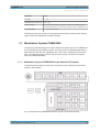
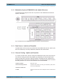
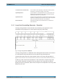
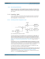
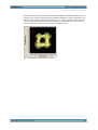
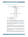
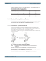
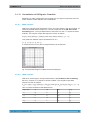
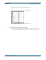
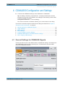
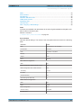
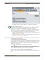
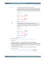
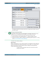
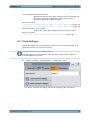
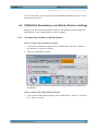
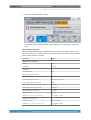
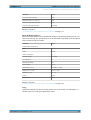
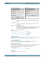
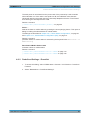
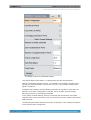
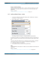

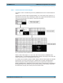
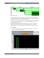
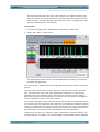
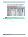
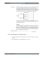
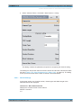
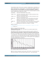
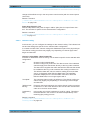
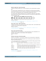
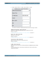
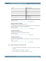
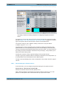

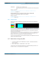
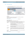
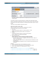
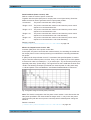
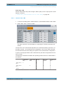
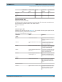
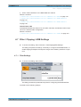
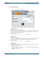
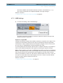
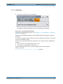
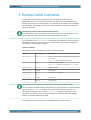

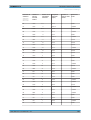

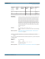


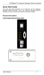

![[:SOURce]:BB:GSM[:FRAMe]](http://vs1.manualzilla.com/store/data/005841236_1-e838b09572e81e9a2469fdab27d799a4-150x150.png)