1
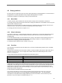
Certified according to DIN ISO 9001 Manual KRD8000 Remote Display for Coriolis Mass Flow Meter SW-Version Main: V2.0x Display: V2.0x Manual-Revision: See rear cover Index 1 GENERAL INFORMATION..................................................................................................................... 5 1.1 1.2 FEATURES........................................................................................................................................................ 5 SAFETY ........................................................................................................................................................... 6 1.2.1 General Safety ............................................................................................................................. 6 1.2.2 Special requirements for Ex installations .................................................................................... 6 1.2.3 Warnings in this manual ............................................................................................................. 6 ORDERING CODES AND ACCESSORIES .................................................................................................................... 7 1.3.1 Ordering Code ............................................................................................................................. 7 1.3.2 Accessories .................................................................................................................................. 7 1.3 2 GETTING STARTED .............................................................................................................................. 8 2.1 2.2 2.3 2.4 UNPACKING ..................................................................................................................................................... 8 OPERATING ELEMENTS....................................................................................................................................... 9 PIN ASSIGNMENTS ............................................................................................................................................ 9 QUICK START ................................................................................................................................................. 10 2.4.1 First Operation .......................................................................................................................... 10 2.4.2 CONTROL Menu ........................................................................................................................ 10 3 INSTALLATION .................................................................................................................................. 11 3.1 3.2 3.3 MECHANICAL ................................................................................................................................................. 11 ELECTRICAL INSTALLATION ................................................................................................................................ 11 3.2.1 Connecting to a KCE8000 .......................................................................................................... 11 3.2.2 Connecting to a KCE6000 .......................................................................................................... 11 EX INSTALLATION ............................................................................................................................................ 12 4 MANUAL OPERATION ....................................................................................................................... 13 4.1 4.2 POWER ON SEQUENCE AND PRINCIPLES OF MANUAL CONTROL ............................................................................... 13 SETUP GUIDELINES .......................................................................................................................................... 15 4.2.1 Meter Mode .............................................................................................................................. 15 4.2.2 Offset Calibration ...................................................................................................................... 15 4.2.3 Flow filter .................................................................................................................................. 15 4.2.4 Cutoff ........................................................................................................................................ 16 4.2.5 Step response ............................................................................................................................ 16 4.2.6 Interaction of the parameters ................................................................................................... 16 MEASURING MODE ......................................................................................................................................... 18 4.3.1 Function of the keys .................................................................................................................. 18 4.3.2 Display selection ....................................................................................................................... 18 4.3.3 Resetting the batch value ......................................................................................................... 18 4.3.4 Error Menu ................................................................................................................................ 18 OFFSET CALIBRATION ....................................................................................................................................... 19 CONTROL MODE ............................................................................................................................................ 20 4.5.1 Function of the keys .................................................................................................................. 20 4.5.2 Submenus in the Main Menu .................................................................................................... 20 4.5.3 ZERO OFFSET Menu ................................................................................................................... 21 4.5.4 DISPLAY Menu ........................................................................................................................... 22 4.5.5 SETUP Menu .............................................................................................................................. 28 4.5.6 SETUP PARAMETER menu ......................................................................................................... 29 4.5.7 SETUP IN/OUTPUS menu........................................................................................................... 32 4.5.8 SETUP DATA CONFIGURATION menu........................................................................................ 37 4.5.9 SETUP RESET TOTAL menu ........................................................................................................ 38 4.5.10 I/O‐TEST Menu .......................................................................................................................... 39 4.5.11 SERVICE Menu ........................................................................................................................... 41 4.3 4.4 4.5 5 REMOTE OPERATION ........................................................................................................................ 42 6 SERVICE AND MAINTENANCE ............................................................................................................ 43 3 Index 6.1 6.2 6.3 6.4 6.5 6.6 MAINTENANCE ............................................................................................................................................... 43 TROUBLE SHOOTING ........................................................................................................................................ 43 CHANGING THE FUSES ...................................................................................................................................... 43 CALIBRATION ................................................................................................................................................. 44 6.4.2 Flow Calibration ........................................................................................................................ 48 SERVICE ........................................................................................................................................................ 49 RELOADING FACTORY SETTINGS ......................................................................................................................... 49 7 LISTINGS ........................................................................................................................................... 51 7.1 7.2 7.3 WARRANTY ................................................................................................................................................... 51 CERTIFICATIONS AND COMPLIANCES.................................................................................................................... 51 TECHNICAL DATA ............................................................................................................................................ 53 7.3.1 Technical Data KCE 8000 Transmitter ....................................................................................... 53 7.3.2 Dimensional Drawings (mm) ..................................................................................................... 54 WEEE AND ROHS .......................................................................................................................................... 55 LIST OF FIGURES .............................................................................................................................................. 55 LIST OF TABLES ............................................................................................................................................... 55 ADDRESSES .................................................................................................................................................... 55 7.4 7.5 7.6 7.7 4 General Information 1 General Information 1.1 Features The TRD8001 is a remote display for the C-Flow Coriolis Mass Flow Meter. It can be used for units with KCE8000 electronics as a second display or for units with the KCE6000 electronics as temporary display for setup or as permanent display. … Fig. 1: KRD8001 5 General Information 1.2 Safety 1.2.1 General Safety All statements regarding safety of operation and technical data in this manual will only apply when the unit is operated correctly in accordance with this manual. The data for Ingress Protection will only apply when all connectors are caped properly with the corresponding counterpart with the same or better IP rating. Cable glands must be populated with cables with the specified diameter and closed properly. The display cover must be closed. During operation all openings of the housing must be closed unless otherwise noted in this manual. All connections to the load and to the supply must be made with shielded cables unless otherwise noted in this manual. This unit must be grounded. As a protection against fire in the positive supply a fuse with a current rating not higher than the current carrying capacity of the cable used is required. Before installing the flow meter and transmitter the user is responsible to ensure that all wetted parts are compatible with the fluid or gas to be measured. The user has to adhere to the instructions for installing electrical devices and corresponding instructions. The devices described in this manual may only be connected and operated by authorized and qualified personnel. 1.2.2 Special requirements for Ex installations The KRD8001 must not be located in hazardous areas. As the KRD8001 has no inputs or outputs except the connection to the KCE electronics, it can be used as a second display, located outside the hazardous area, for a KCE8000 electronics located inside the hazardous area. 1.2.3 Warnings in this manual NOTE: Notes provide important information for the correct usage of the equipment. If the notes are not observed, a malfunction of the equipment is possible. WARNING! Warnings provide very important information for the correct usage of the equipment. Not observing the warnings may lead to danger for the equipment and to danger for health and life of the user 6 General Information 1.3 Ordering Codes and Accessories 1.3.1 Ordering Code Ordering Code Description KRD8001 Remote display for C-Flow coriolis mass flow meter KRD8001-Ex KRD8001 for hazardous areas, zone 2 (ATEX II 3G Ex nA IIC T4) 1.3.2 Accessories Ordering Code Description (Contact KEM) Connecting Cable KRD KCE8000 electronics (Contact KEM) Connecting Cable KRD KCE6000 electronics 7 Getting Started 2 Getting started 2.1 Unpacking Verify that you have received the following items: 8 KRD8001 User’s manual Connecting cable to the C-Flow (when ordered) Getting Started 2.2 Operating Elements 2 1 3 4 10 9 8 7 6 5 Fig. 2: Operating Elements of KCE80xx-SG 1 = Pushbutton “P”, activates / selects the different menus and confirms the settings 2 = LED “OK”, flashes green when there is no error 3 = LED “ERR”, flashes red when an error occurs 4 = Display 5 = Pushbutton “Info”, normal: selects the status menu, SETUP: softkey 6 = Pushbutton “Display”, normal: toggles the display, SETUP: softkey 7 = I/O connector 8 = Pushbutton “Reset”, normal: resets the batch counter, SETUP: softkey 9 = Side cover 10 = Mounting hole 2.3 Pin Assignments The I/O connector is an M12 connector, B coded, male. I/O connector pin assignment 1 + 24V Positive supply 2 - RS485 RS485 negative line 3 GND Supply ground 4 +RS485 RS485 positive line 5 n.c. 9 Getting Started 2.4 Quick start WARNING! As for safety and accuracy reasons many precautions must be taken, read chapter 3 carefully before installing the unit! If the unit is connected to a bigger system, for your personal make sure that the protective ground is connected! In case the KRD8000 has to be used with a KCE6000, just connect it via the standard cable available from KEM. If the KRD8000 is to be used with a KCE8000, connect the cable available from KEM in the KCE8000 according to the KCE8000 manual. 2.4.1 First Operation Make sure that all mechanical and electrical connections are made properly. Switch on the power supply. The LED “OK” will flash green. After the power up sequence the display shows the preselected values (ex factory normally flow and batch) Switch on the flow. The value indicated in the display should be positive. In case of an error the LED “ERR” will flash red. The display can be altered by pressing the key “Display”. The error code, the device status and information like serial number, SW version a.s.o. can be viewed by pressing the key “Info” for 3 seconds. If the function is activated, the BATCH reading can be reset to zero by pressing the key “Reset”. For entering the CONTROL menu press “P” for 3 seconds. 2.4.2 CONTROL Menu In the CONTROL menu all configurations can be made. This includes configuration of the analogue and digital outputs, customizing the display and other settings. The menu itself is self-explaining, the function of the softkeys (5, 6, 7) is indicated in the display above the pushbutton. For entering the CONTROL menu press the pushbutton “P” (4) for 3 seconds. The submenu DISPLAY can be entered without a password as any changes in this submenu will not affect the operation of the unit. The submenus SETUP, I/O-TEST and SERVICE are password protected for avoiding unintentional changes of the operating parameters. For SETUP and I/O-TEST the password is “2207”, for SERVICE refer to chapter 6.4. Change the indicated number “2206” with the softkey “up” (6) to “2207” and confirm with “P” (4). Select the desired submenu with the softkeys and confirm with “P” (4). Every setting must be confirmed with “P” (4) for storing the setting or with “E” for exiting without storing. For leaving the SETUP menu press “E” (7) in the main level. 10 Installation 3 Installation 3.1 Mechanical The KRD8000 can be used as a handheld display for fast setting or check at an KCE6000 electronics or as wall mounted display. For wall mount provide 2 or 4 fixing points according to the drawing in chapter 7.3.2. Flip up the side covers of the housing, fix the housing with suitable screws to the wall and reclose the side covers. NOTE It is not necessary to open the housing for mounting the KRD8000. 3.2 Electrical installation Make sure that the unit is properly mounted and the process input and output are connected before making the electrical connections. The KRD8000 can be connected to or disconnected from the C-Flow electronics at any time via the M12 connector at the KRD8000, without switching off the power supply and without disturbing the operation of the CFlow meter. 3.2.1 Connecting to a KCE8000 Switch off the power supply for the C-Flow and prepare the KCE8000 for installing the cables (see manual C-Flow with KCE8000). Connect the cable to the KCE8000 according to Tab. 1. If possible use end sleeves for the individual wires. Terminal M12 conn. 1 2 3 4 5 Shield Signal + 24V -RS485 GND +RS485 n. c. Protective ground Color Yellow Green Grey Pink Terminal KCE8000 50 21 8 or 20 or 51 22 Tab. 1: Connections KCE8000 Connect the M12 connector of the cable to the KRD8000. 3.2.2 Connecting to a KCE6000 Connect the male connector of the cable to the connector “RS485” of the KCE6000. Connect the female connector of the cable to the KRD8000. 11 Installation 3.3 Ex Installation WARNING! In hazardous locations all installations must only be carried out by qualified personnel! Switch off all power supplies before installing or uninstalling the unit in hazardous locations! The KRD8000 is available for hazardous areas, zone 2 (II 3G Ex nA IIC T4). The KRD8000 can as well be used as a secondary display outside the hazardous area for a C-Flow with KCE8000 electronics located inside the hazardous area. WARNING! Never install any KRD8000 in zone 0 or 1! Connect the KRD to the KCE6000 or KCE8000 as described in chapter 3.2 12 Manual Operation 4 Manual Operation 4.1 Power On Sequence and Principles of Manual Control The power up sequence gives the following information, each for about 2 second: CORIOLIS C-FLOW KCE8000 This gives the type of electronics. At the time being the types KCE8001 (low power) and KCE8011 (high power) are available. SENSOR TYPE KCM0300 This gives the sensor size. At the time being Sensors from KCM0300 (300kg/h max.) to KCM3000k (3000kg/h max.) are available SW MAIN Rev.: V2.00 This indicates the SW version of the main processor. SW DISPLAY Rev.: V2.00 This indicates the SW version of the display processor. READY If changes to the settings were made before the last power down and not saved to the backup EEPROM, the following message appears: 13 Manual Operation ***……. WARNING …….*** NO ACTUAL RAM BACKUP SEE MANUAL OK If no key is pressed the warning will disappear automatically after 10 seconds. For further information refer to chapter 4.5.8. Now the KCE8000 switches to the measuring mode, displaying the default screen: 0.000RATE 0.00TOTAL The green LED “OK” flashes with a 1 second period. In case of an error the red LED “ERR” flashes. In manual control the KCE is menu driven and provides 2 operational modes, the “Measuring Mode” and the “Control Mode”. In the measuring mode the display shows the preselected measured values and all 4 pushbuttons have the function printed on them. The switch over between the different measuring displays and the error display can be made at any time without interrupting the measurements. In the control mode the 3 pushbuttons below the display have varying functions. The actual function is indicated in the display, just above the pushbutton. In the control menu all necessary settings can be made. The control menu contains the 5 submenus “ZERO OFFSET”, “DISPLAY”, “SETUP”, “I/O-TEST” and “SERVICE”. For protecting the unit against unintentional changes by unauthorized personnel, the menus “ZERO OFFSET”, “SETUP” and “I/O-TEST” are protected by a user password and the menu “SERVICE” by a service password. For the description of the control menu see chapter 4.5. 14 Manual Operation 4.2 Setup guidelines Ex factory the C-Flow mass flow meter come with a setup optimized for normal applications. In more than 90% of the applications no further optimization except a regular offset adjustment is required. The different possibilities for optimizing the settings are described below. 4.2.1 Meter Mode A coriolis mass flow meter measures the mass flow and the density and can calculate the volume flow. For avoiding strange effects with the total values when changing the dimensions, the KCE8000 can be set up as a mass flow OR a volume flow meter. When set up as mass flow meter, only mass and mass flow engineering units can be selected, when set up as volume flow meter, only volume and volume flow engineering units can be selected. For changing the meter mode refer to chapter 4.5.6.1. 4.2.2 Offset Calibration In contrast to a PD meter, a coriolis mass flow meter has no “natural” zero. At no flow the measured time shift is nearly zero, but not exactly. The offset calibration determines this offset and corrects the measured value correspondingly. As the offset depends slightly upon the temperature, the density of the medium and the operating pressure, it is strongly recommended to make the offset procedure under working conditions, i.e. with the medium to be measured and at operating pressure and temperature. For making the offset calibration refer to chapter 4.4 and 4.5.3. 4.2.3 Flow filter The rough data of a mass flow meter are relative noisy. For having a stable reading a filtering of the calculated flow is required. The filters in the KCE8000 are set via the time constant t. The time constant is the time the output needs after a jump from x to 0 to go to x/e = x/2.72. A higher time constant means more stable reading but also a slower reaction to changing flows. A rough relation between the time and the filtered flow value after a jump is Elapsed time 1*t 2*t 3*t 4*t Remaining error (% of the step) 30 10 3 1 A linear filter as it is realized in the KCE8000 electronics just delays the flow reading and consequently the total. Independent of the slope (fast or slow) of the rising and falling flow, the error of the internally calculated total and at the frequency output cancel out, if the flow rises from zero (or any other value) and later goes back to the starting value. For getting a correct total via the display or the frequency output, it is just necessary to wait long enough after the flow is switched off. For best results the KCE8000 electronics provide 2 filters. The FLOW FILTER filters the mass flow before calculating other parameters like volume flow, total or the frequency and current outputs. For normal applications a moderate filtering with t = 1s is recommended. The DISPLAY FILTER filters the flow display additionally to the FLOW FILTER. It does not affect any other parameter or any of the outputs. The default setting is t = 1s. 15 Manual Operation If the flow is fast changing or sometimes makes a jump and the outputs have to react as fast as possible, set FLOW FILTER to t < 1s. If nevertheless the flow display has to be stable for better readability, the DISPLAY FILTER can be increased. For setting up the FLOW FILTER refer to chapter 4.5.6.2, for the DISPLAY FILTER to chapter 4.5.4.1. 4.2.4 Cutoff As mentioned above, a mass flow meter has no natural zero and the rough data are noisy. Consequently with now flow a meter would indicate and give out continuously a small fluctuating flow. The parameter CUTOFF is used to provide a clear zero. If the calculated and filtered flow is below cutoff, the meter indicates zero, the total values remain unchanged and the outputs show zero flow as well. The value for CUTOFF must be above the noise floor in the given application and well below the minimum flow to be measured. As a good compromise the default value for CUTOFF is 0.5% of the full scale range of the meter. For setting CUTOFF refer to chapter 4.5.6.3. 4.2.5 Step response Sometimes it is necessary to react fast to a fast changing flow, but also to have a stable output, if the flow is (mostly) constant. This cannot be achieved by adjusting the flow filter. The parameter STEP RESPONSE provides a fast reaction at fast changing flow, also the filter constant is high. If the difference between the measured flow and the filtered flow is smaller than the step response value, the flow filter remains active. If the difference is higher than step response, the filter is cleared and filled with the new value. The recommended value for constant or slowly changing flow is 99% (the default value ex works). If the unit has to react to fast changing flow, the optimum value depends on the individual situation. For ON / OFF operation a value of half the ON flow is recommended. If STEP RESPONSE is set too low, even small changes in flow or even the internal noise will activate the step response function and partially or all the time deactivate the filter, leading to noisy readings and noisy output signals. For setting STEP RESPONSE refer to chapter 4.5.6.4. 4.2.6 Interaction of the parameters As each of the 3 parameters affects the calculation of the flow in a different way, a bad combination of different parameters can lead to systematical errors. FLOW FILTER and CUTOFF If the filter constant is set to a high value, the calculated flow is delayed compared to the actual flow. In ON-OFF operation this leads to the fact that it takes a long time until the calculated flow settles to the ON or OFF value. The total value remains correct if the unit measures long enough after the flow got switched off. If cutoff is set to a high value, the meters stops measuring too early and consequently the calculated total is too low. Also the number of pulses at the frequency output is too low. The error is systematic. NOTE In ON-OFF operation high values for the flow filter combined with high values for cutoff must be avoided! Jumps of the flow not going down to zero are not affected by cutoff. FLOW FILTER and STEP RESPONSE As described above, a linear filter just delays the flow reading and consequently the total but does not alter the final total. If the step response is activated, a nonlinear term is added to the filter. The indicated flow will follow more closely the total flow, but the remaining deviation depends on the values for the filter and for step response, but also on the slope of the flow change and on the size of a step. 16 Manual Operation If the flow changes slowly or a jump is smaller than step response, the step response function will not be activated and remains linear all the time, producing the normal delay. If the flow changes fast and the step is higher than step response, the filter will be made faster, the indicated flow follows more closely the actual flow and the delay will be smaller. In ON-OFF operation with a fast rising and slowly falling flow a systematic positive error is to be expected. If the rising is slow and the falling fast, the error will be negative. WARNING! If step response is used (e.g. for good reaction to fast changing flow), checking the accuracy for the given application is strongly recommended! 17 Manual Operation 4.3 Measuring mode 4.3.1 Function of the keys In the measuring mode all pushbuttons have a fixed function: P Opens the Control Menu if pressed for about 3 seconds Reset Resets the batch counter to zero, if the function “KEY RESET” is enabled Display Toggles the display between the 2 preselected settings. Info Opens the info menu 4.3.2 Display selection The KCE provides 2 presettable displays. Ex work display 1 shows the flow and the total value, display 2 shows density and temperature. In the “fixed mode” the display selected by the user remains active until the other display is selected. For changing from on display to the other just press the pushbutton “Display”. In the “alternate mode” the unit toggles between display 1 and 2 every 5 seconds. In this mode the pushbutton “Display” is without function. For changing the content of the 2 displays refer to chapter 4.5.4. 4.3.3 Resetting the batch value For easy batching in local operation the KCE provides the possibility to reset the batch value by pressing the pushbutton “Reset”. For protecting the unit against unintentional resetting of the batch value, this function can be disabled. Ex work the function is disabled. For changing the setting refer to chapter 4.5.7.4. 4.3.4 Error Menu For easy debugging in case of a malfunction of the system, the KCE provides an info and error menu. The content of the info and error menu is not of interest for normal operation and some information is only readable for trained personnel. For entering the menu press the pushbutton “Info” for about 3 seconds. The display shows “NO ERROR” or one or more of the following error messages: Code 1 2 3 4 5 6 7 8 9 Tab. 2: Error Codes 18 Error Amplitude sensor A is out of range (too high or too low) Amplitude sensor B is out of range (too high or too low) Measured time delay is too high Offset adjust procedure is in progress Driver current is not stable Temperature sensor is out of range. Typically indicated if the line is broken or has a short Oscillating frequency too low Oscillating frequency too high Driver current too low Manual Operation Press “Info” a second time for getting 8 internal operating parameters: Code SA SB DR PT FRE DEN OFF RUN Value Sensor voltage A in mV Sensor voltage B in mV Driver current in mA Measured Temperature in °C Oscillating frequency in Hz Density Actual offset value Actual time shift Tab. 3: List of service parameters Press “Info” again for getting general information about the unit: Code TYPR: SER.: SW1: SW2: Value Sensor type (KCM*) Serial number SW version main board SW version display Tab. 4: List of unit info By pressing “Info” you can toggle between those 2 displays, for returning to the normal operation press “Display”. 4.4 Offset calibration For best accuracy the C-Flow needs an in situ offset calibration. This calibration zeroes out the ambient effects and increases the measuring accuracy at low flow. The offset calibration must be carried out with the medium to be measured and should be carried out at a temperature and pressure as close to the normal operation as possible. Proceed as follows: Operate the unit for a while under normal operating conditions for making sure that the actual temperature of the unit equals the normal operating temperature. Switch off the flow. For best results use a valve in front and one behind the KCM. If the valves are not close to the KCM and / or only one valve is used, wait long enough for being sure that there is no more flow through the KCM. NOTE: If there is a residual flow through the KCM or the KCM is exposed to mechanical shocks during the offset procedure, the resulting value will be wrong. Start the offset procedure as follows (see also chapter 4.5.3): Press “P” for about 3 seconds The display shows “ZERO OFFSET” Press “P” Change the indicated number with “up” to 2207 and confirm with “P” Press “SLOW” (recommended) or “FAST” The display shows “MAKE ZERO” for 10 to 30 s and counts down to “0” Confirm with “Info” The offset procedure takes about 10 s (fast) or 25 – 30 s (slow). During the procedure the red LED will flash. For an automatic offset calibration initiated by the central control unit, the control input can be configured as “initiate offset”. In that case the KCE starts an offset procedure each time a high level is applied to the input. For configuring the input refer to chapter 4.5.7.4. 19 Manual Operation 4.5 Control Mode In the control mode the KCE8000 can be adapted to the individual application. As unintentional changes of the settings might cause problems, some submenus are password protected. To enter the control mode proceed as follows: Press “P” for about 3 seconds The display shows: MAIN MENU ZERO OFFSET UP DOWN EXIT With the keys “UP” and “DOWN” you can scroll through the main list. Select the desired submenu and confirm with “P”. 4.5.1 Function of the keys In the setup menu some pushbuttons have changing functions, indicated in the display above the pushbutton: P Confirms the selection in a list or any kind of inputs Reset Performs the indicated function Display Performs the indicated function. Info Performs the indicated function. In most cases exits the current menu point without altering the original value 4.5.2 Submenus in the Main Menu In the Main Menu the following submenus are addressable: ZERO OFFSET: Performing the automatic offset procedure. This submenu is password protected. DISPLAY: Presetting the display. Changes made in this submenu have no influence on the general function as well on the accuracy of the unit. SETUP: Adjusting the KCE8000 and configuring the inputs and outputs. This submenu is password protected. I/O-TEST: Setting the outputs to defined values and displaying the actual status of the control inputs for testing the electrical connections. This submenu is password protected. SERVICE: Calibrating KCE8000. This submenu is password protected. 20 Manual Operation 4.5.3 ZERO OFFSET Menu Select in the main menu MAIN MENU ZERO OFFSET UP DOWN EXIT Press “P”. The display shows ENTER CODE 2206 LEFT UP EXIT Change the indicated number with “LEFT” and “UP” to 2207 and confirm with “P”. If a wrong code is entered, the display shows “ERROR” for about 2s and then asks for a new input. When the correct code is entered the display shows: START OFFSET PROCEDURE SLOW FAST EXIT Press “SLOW” or “FAST”. The display shows MAKE ZERO OLD ZERO: NEW ZERO: 10µs 0.000µs µs The time counter counts down to zero. The display shows: * END OF ZERO-POINT * OLD ZERO: 0.000µs NEW ZERO: 0.123µs EXIT Press “EXIT” to return to the measuring mode. 21 Manual Operation 4.5.4 DISPLAY Menu NOTE: If the KRD8000 is used as a second display for a KCE8000 electronic, the display settings of both units except the flow filter will not influence each other. Select in the main menu MAIN MENU DISPLAY UP DOWN EXIT Press “P”. The display shows DISPLAY MENU FLOW DISPLAY UP DOWN EXIT The following submenus are available: FLOW DISPLAY: Setting the flow units, the flow decimal point and a flow filter for the display. TOTAL DISP: Setting the total and batch units and the total and batch decimal point. DENS DISP: Setting the density units. TEMP DISP: Setting the temperature units. DISP MODE: Setting the content of the 2 screens, the mode (static or alternating) and the backlight. 4.5.4.1 FLOW DISPLAY menu In the submenu “FLOW DISPLAY” the flow dimensions, the flow decimal point and the flow filter for the display can be set. DISPLAY MENU FLOW DISPLAY UP DOWN EXIT SET FLOW DISPLAY P FLOW UNITS UP DOWN EXIT Use the keys “UP” and “DOWN” to select the desired submenu and confirm with “P” or skip with “EXIT”. The following submenus are available: FLOW UNITS: Setting the flow units. FLOW DP: Setting the flow decimal point. DISP FILTER: Setting the display filter. 22 Manual Operation FLOW UNITS SET FLOW DISPLAY FLOW UNITS UP DOWN SELECT MASS UNITS G/S P EXIT UP DOWN EXIT Depending on the selected meter mode (mass flow meter or volume flow meter) the display says “SELECT MASS UNITS” or “SELECT VOLUME UNITS” and provides correspondingly only mass or volume units. The meter mode can only be changed in the SETUP menu (see chapter 4.5.6.1) The following units (volume or mass per time) can be selected: time-Unit Description S MIN H D second minute hour day Mass-Unit Description G KG LB OZ T ST gram kilogram pound dry ounce metric ton stone Volume-Unit Description CC L m3 UGAL LOZ EGAL BBL cubic centimeter liter cubic meter US gallon fluid ounce English gallon English barrel Use the keys “UP” and “DOWN” to select the engineering unit and confirm with “P” or skip with “EXIT”. FLOW DP SET FLOW DISPLAY FLOW DP UP DOWN SELECT FLOW DP P EXIT 000.0 LEFT G/S EXIT Use the key “LEFT” to select the desired decimal point position and confirm with “P” or skip with “E”. DISP FILTER SET FLOW DISPLAY DISP FILTER UP DOWN EXIT DISPLAY FILTER (0-99s) P 1.00000 s RIGHT UP EXIT The time constant t is the time the displayed value needs after a jump from x to 0 to go to x/e = x/2.72. 23 Manual Operation NOTE: The display filter only filters the value in the display for providing a more stable reading. It has no influence on the outputs. As the display filter is additional to the global filter, the display can never react faster than the outputs. Use the keys “RIGHT” and “UP” to select the desired time constant and confirm with “P” or skip with “EXIT”. 4.5.4.2 TOTAL DISP menu In the submenu “TOTAL DISPL” the total and batch dimensions and decimal point can be set. DISPLAY MENU TOTAL DISPL UP DOWN SET TOTAL DISPLAY P EXIT TOTAL UNITS UP DOWN EXIT Use the keys “UP” and “DOWN” to select the desired submenu and confirm with “P” or skip with “EXIT”. The following submenus are available: TOTAL UNITS: Setting the total units. TOTAL DP: Setting the total decimal point. TOTAL UNITS SET TOTAL DISPLAY TOTAL UNITS UP DOWN EXIT SELECT TOTAL UNITS KILO P UP DOWN EXIT Depending on the selected meter mode (mass flow meter or volume flow meter) only mass or volume units can be selected. The meter mode can only be changed in the SETUP menu (see chapter 4.5.6.1) The following units can be selected: Mass-Unit Description G KG LB OZ T ST gram kilogram pound dry ounce metric ton stone Volume-Unit Description CC L m3 UGAL LOZ EGAL BBL cubic centimeter liter cubic meter US gallon fluid ounce English gallon English barrel Use the keys “UP” and “DOWN” to select the engineering unit and confirm with “P” or skip with “EXIT”. 24 Manual Operation TOTAL DP SET TOTAL DISPLAY TOTAL DP UP DOWN SELECT TOTAL DP 000.0 P EXIT G/S LEFT EXIT Use the key “LEFT” to select the desired decimal point position and confirm with “P” or skip with “E”. 4.5.4.3 DENS DISPLAY menu In the submenu “DENS DISPLAY” the density dimension can be set. DISPLAY MENU DENS DISP UP DOWN SELECT DENS UNIT KG/L P EXIT UP DOWN EXIT The following units (mass per volume) can be selected: Unit Description G/CC G/L KG/L LB/FT3 LB/GAL KG/M3 BRIX gram per cubic centimeter gram per liter kilogram per liter pound per cubic feet pound per US gallon kilogram per cubic meter Brix Use the keys “UP” and “DOWN” to select the engineering unit and confirm with “P” or skip with “EXIT”. 4.5.4.4 TEMP DISP menu In the submenu “TEMP DISP” the temperature engineering unit can be set. DISPLAY MENU TEMP DISP UP DOWN EXIT SELECT TEMP UNIT °C P UP DOWN EXIT The following units can be selected: Unit Description °C °F KELVIN Centigrade Fahrenheit Kelvin Use the keys “UP” and “DOWN” to select the engineering unit and confirm with “P” or skip with “EXIT”. 25 Manual Operation 4.5.4.5 DISP MODE menu In the submenu “DISP MODE” the display mode can be set. DISPLAY MENU SET DISPLAY MODE DISP MODE UP DOWN DISPLAY 1 P EXIT UP DOWN EXIT Use the keys “UP” and “DOWN” to select the desired submenu and confirm with “P” or skip with “EXIT”. The following submenus are available: DISPLAY 1: Setting the content of display 1. DISPLAY 2: Setting the content of display 2. BACKLIGHT: Switching on and off the backlight. TIME MODE: Setting fixed or alternating display. DISPLAY 1 SET DISPLAY MODE SET DISPLAY 1 MODE DISPLY 1 UP DOWN DUAL LINE P EXIT UP DOWN EXIT Use the keys “UP” and “DOWN” to select dual line or single line and confirm with “P” or skip with “EXIT”. The display shows SELECT LINE1 VALUE RATE UP DOWN EXIT The following values can be selected: Unit Description RATE BATCH DENS: TEMP. TOTAL F-OUT CURR-1 CURR-2 Actual flow Batch count Density Temperature Total count Actual frequency at the frequency output Actual currant at the analog output 1 Actual currant at the analog output 2 Use the keys “UP” and “DOWN” to select the desired value and confirm with “P” or skip with “EXIT”. 26 Manual Operation The display shows SELECT LINE2 VALUE BATCH TOTAL UP DOWN EXIT Use the keys “UP” and “DOWN” to select the desired value and confirm with “P” or skip with “EXIT”. The unit returns to the display mode menu. DISPLAY 2 See DISPLAY 1 BACKLIGHT SET DISPLAY MODE BACKLIGHT UP DOWN SET BACKLIGHT MODE ON P EXIT UP DOWN EXIT Use the keys “UP” and “DOWN” to switch on or off the backlight and confirm with “P” or skip with “EXIT”. TIME MODE SET DISPLAY MODE TIME MODE UP DOWN EXIT SET TIME MODE FIXED P UP DOWN EXIT In the fixed mode the display shows constantly the defined display 1 or 2. With the pushbutton “Display” it is possible to switch over between display 1 or 2. In the alternate mode the display switches over every 7 seconds between display 1 and 2. Use the keys “UP” and “DOWN” to select the desired mode and confirm with “P” or skip with “EXIT”. 27 Manual Operation 4.5.5 SETUP Menu In the SETUP menu all settings can be made to adapt the meter to the individual requirements. Select in the main menu MAIN MENU SETUP UP DOWN EXIT Press “P”. The display shows ENTER CODE 2206 LEFT UP EXIT Change the indicated number with “LEFT” and “UP” to 2207 and confirm with “P”. If a wrong code is entered, the display shows “ERROR” for about 2s and then asks for a new input. When the correct code is entered the display shows: SETUP MENU PARAMETER UP DOWN EXIT The following submenus are available: PARAMETER: METER MODE FLOW FILTER CUT OFF STEP RESP: RESET KEY FLOW-DIREC K-FACTOR FAULT TIME LANGUAGE Selecting mass or volume meter mode Setting the filter time constant Setting the cutoff value Adjusting the settings for fast changing flow Enable / disable the key “Reset” Setting up the unit for reverse flow Fine scaling the meter Setting the error response time Selecting the display language IN/OUTPUTS: FREQ OUT CTRL OUT ANALOG OUT CTRL IN INTERFACE Configuring the frequency output Configuring the control output Configuring the analog output Configuring the control input Configuring the interface DATA CONFIG: SAVE DATA RECALL DATA Saving the actual settings as backup recalling the last settings from the backup RESET TOTAL: Resets the total count to zero. Use the keys “UP” and “DOWN” to select the desired submenu and confirm with “P” or skip with “E”. 28 Manual Operation 4.5.6 SETUP PARAMETER menu In the submenu SETUP / PARAMETER all user settable internal parameter can be set for adjusting the unit for a given application. SETUP MENU PARAMETER MENU PARAMETER UP DOWN METER MODE P EXIT UP DOWN EXIT Use the keys “UP” and “DOWN” to select the desired submenu and confirm with “P” or skip with “E”. 4.5.6.1 METER MODE menu In the submenu “METER MODE” can be set, if the flow meter shall be used as a mass flow meter or a volume flow meter. If “mass flow meter” is selected, no volume units can be displayed and vice versa. PARAMETER MENU SELECT METER MODE METER MODE UP DOWN MASS METER P EXIT UP DOWN EXIT Use the keys “UP” and “DOWN” to select the desired submenu and confirm with “P” or skip with “E”. If the mode is changed, the display shows: WARNING! YES NO Then the following message scrolls through the display: WARNING! CHANGING THE METER MODE WILL RESET ALL UNITS AND THE TOTAL COUNTER. DO YOU WANT TO PROCEED? Confirm with “YES” or skip with “NO”. The display returns to the setup parameter menu. 4.5.6.2 FLOW-FILTER menu In the submenu “FLOW-FILTER” the time constant for the flow filter can be set. The time constant is the time the output needs after a jump from x to 0 to go to x/e = x/2.72. A rough relation between the time and the filtered flow value after a jump is Elapsed time 1*t 2*t 3*t 4*t Remaining error (% of the step) 30 10 3 1 29 Manual Operation PARAMETER MENU FLOW FILTER UP DOWN FLOW FILTER 0-99.9s 1.00000 P EXIT RIGHT UP EXIT Use the keys “RIGHT” and “UP” to select the desired value and confirm with “P” or skip with “EXIT”. The display returns to the setup parameter menu. 4.5.6.3 CUT OFF menu In the submenu “CUT-OFF” the cutoff in percent of the full scale flow range can be set. If the absolute value of the measured and filtered flow is below the cutoff value, the calculated flow is “0” and consequently all outputs show zero flow and the total and batch value remain unchanged. PARAMETER MENU CUT OFF UP DOWN CUTOFF RATE (%) 0.5 P EXIT RIGHT UP EXIT Use the keys “RIGHT” and “UP” to select the desired value and confirm with “P” or skip with “EXIT”. The display returns to the setup parameter menu. 4.5.6.4 RESP STEP menu In the submenu “RESP STEP” the reaction to fast changing flows can be set. If the difference between the measured flow and the filtered flow is smaller than the step response value, the flow filter remains active. If the difference is higher than step response, the filter is cleared and filled with the new value. The recommended value for constant or slowly changing flow is 99% (the default value ex work). If the unit has to react to fast changing flow, the optimum value depends on the individual situation. For ON / OFF operation a value of half the ON flow is recommended, if this is less than the default 10%. NOTE: A too low value will lead to noisy measurement whereas a too high value with fast changing flow (ON /OFF operation) will lead to a too slow reaction of the meter. PARAMETER MENU RESP STEP UP DOWN EXIT RESPONSE STEP (%) 99.0 P RIGHT UP EXIT Use the keys “RIGHT” and “UP” to select the desired value and confirm with “P” or skip with “EXIT”. The display returns to the setup parameter menu. 30 Manual Operation 4.5.6.5 RESET KEY menu In the submenu “RESET-KEY” the pushbutton “Reset” can be enabled or disabled. If the pushbutton Reset is active, it can be used to reset the batch counter. PARAMETER MENU SELECT RES.KEY MODE RESET KEY RES. KEY OFF UP DOWN P EXIT UP DOWN EXIT Use the keys “UP” and “DOWN” to enable or disable the key and confirm with “P” or skip with “EXIT”. The display returns to the setup menu 4.5.6.6 FLOW DIRECTION menu In the submenu “FLOW-DIREC” the positive direction of the flow can be set. If flow direction is “forward” (default setting), a flow through the meter in direction of the arrow on the meter will be displayed positive, the opposite flow negative. If for technical reasons the meter must be mounted in that way, that the normal flow is against the direction of the arrow, the sign of the flow can be inverted by setting flow direction to “reverse”. PARAMETER MENU FLOW-DIREC UP DOWN FLOW-DIRECTION P EXIT FORWARD UP DOWN EXIT Use the keys “UP” and “DOWN” to select the positive flow direction and confirm with “P” or skip with “EXIT”. The display returns to the setup menu 4.5.6.7 K-FACTOR menu In the submenu “K-FACTOR” the k- factor for fine tuning of the flow calculation can be set. Ex work the unit is calibrated with a k- factor of “1”. If for any reasons the flow measured by the mass flow meter differs slightly from a flow measured with other means, the value calculated by the KCM8000 can be adjusted by changing the k- factor. PARAMETER MENU K-FACTOR UP DOWN EXIT K-FACTOR P 1.00000 RIGHT UP EXIT Use the keys “RIGHT” and “UP” to select the desired value and confirm with “P” or skip with “EXIT”. The display returns to the setup parameter menu. 31 Manual Operation 4.5.6.8 FAULT TIME menu In the submenu “FAULT TIME” the reaction time of the KCE8000 in case of an error can be defined. The fault on delay time is the time an error must be present, until the red LED lights up and the error output signal is activated. The fault off delay time is the time an error signal persists on the red LED and on the control output, after the error disappeared. PARAMETER MENU FAULT ON DELAY TIME FAULT TIME UP DOWN 2.7000 SECONDS P EXIT RIGHT UP EXIT Use the keys “LEFT” and “UP” to select the desired value and confirm with “P” or skip with “E”. The display shows FAULT OFF DELAY TIME 2.7000 SECONDS RIGHT UP EXIT Use the keys “LEFT” and “UP” to select the desired value and confirm with “P” or skip with “E”. The display returns to the setup menu. 4.5.6.9 LANGUAGE menu In the submenu “LANGUAGE” the language used in the display can be selected. At the time being English and Russian can be selected. If Russian is selected, only the main menu is in Russian language, the control menu remains in English. PARAMETER MENU LANGUAGE UP DOWN SELECT LANDUAGE P EXIT ENGLISH UP DOWN EXIT Use the keys “UP” and “DOWN” to select the language and confirm with “P” or skip with “E”. The display returns to the setup menu. In case you cannot read the display the menu can be accessed by: 3s P/Display/Display/P/Display/P/P/Reset/P 4.5.7 SETUP IN/OUTPUS menu In the submenu SETUP / IN/OUTPUTS the input and output ports of the KCE8000 can be configured. SETUP MENU IN/OUTPUT UP DOWN EXIT IN/OUTPUTS MENU P FREQ OUT UP DOWN EXIT Use the keys “UP” and “DOWN” to select the desired submenu and confirm with “P” or skip with “E”. 32 Manual Operation 4.5.7.1 FREQ OUT menu In the submenu “FREQ OUT” the frequency output can be configured. The frequency output has 2 operating modes: FREQUENCY: A frequency proportional to the actual flow is generated. If a negative flow must be given out as well, the control output can be used as sign. Frequencies between 2Hz and 10kHz can be generated in this mode. TOTAL COUNT: Each time the total increments by the selected total increment step, the output produces a pulse. For having a 50% duty cycle, the output changes its state each time after half the increment step. If the flow is negative in between, no pulses are generated until the following positive flow compensates for the negative flow in between. Thus the medium will not be counted twice, if in between a flow backwards occur. The maximum output frequency which can be generated in this mode is about 50Hz. IN/OUTPUTS MENU FREQ OUT MENU FREQ OUT UP DOWN FREQUENCY P EXIT UP DOWN EXIT Use the keys “UP” and “DOWN” to select the desired mode and confirm with “P” or skip with “E”. FREQUENCY FREQ OUT MENU FULL SCALE FLOW FREQUENCY UP DOWN 8000.0 G/S P EXIT RIGHT UP EXIT Use the keys “RIGHT” and “UP” to select the desired full scale value and confirm with “P” or skip with “EXIT”. The display shows FULL SCALE FREQUENCY 01000.0 HZ RIGHT UP EXIT Use the keys “RIGHT” and “UP” to select the desired frequency and confirm with “P” or skip with “EXIT”. The display shows OUTPUT NEGATIVE VALUES YES NO If “YES” is selected and the control output is not configured as sign output, the display shows CHANGE CONTROL OUTPUT TO FREQ OUT DIRECTION TO PROCEED . OK Confirm with “OK” and configure the control output correspondingly if required. 33 Manual Operation TOTAL COUNT FREQ OUT MENU SELECT VALUE TOTAL COUNT UP DOWN P EXIT 0.10000 KILO RIGHT UP EXIT Use the keys “RIGHT” and “UP” to select the desired increment step and confirm with “P” or skip with “EXIT”. 4.5.7.2 CONTROL OUT menu In the submenu “CTRL OUT” the control output can be configured. The control output has 3 operating modes: BATCH: In the batch mode the KCE8000 operates as a batch counter. If the preset batch value is reached, the control output goes to the active state. With an active signal at the control input the batch counter can be reset to zero. For this mode the control input must be configured as “reset batch”. FAULT: In case of an error the control output goes high. For setting the on and off delay time refer to chapter 4.5.6.8. FLOW DIREC: The control output is low, if a positive flow is measured, and high, if a negative flow is measured. IN/OUTPUTS MENU CTRL OUT MENU CTRL OUT UP DOWN BATCH P EXIT UP DOWN EXIT Use the keys “UP” and “DOWN” to select the desired mode and confirm with “P” or skip with “E”. If FAULT or FLOW DIREC was selected, the KCE changes the settings and returns to the IN/OUTPUT menu. If BATCH was selected, the display shows BATCH LIMIT 0.50000 KG RIGHT UP EXIT Use the keys “RIGHT” and “UP” to select the desired batch value and confirm with “P” or skip with “EXIT”. The display shows SELECT OUTPUT LEVEL ACTIVE HIGH UP DOWN EXIT Use the keys “UP” and “DOWN” to select the desired value and confirm with “P” or skip with “E”. 34 Manual Operation 4.5.7.3 ANALOG OUT menu In the submenu “ANALOG OUT” the 4 – 20mA outputs can be configured. When used with a KCE6000, only 1 analog output is available. Each analog output can show one of the following 4 parameters: FLOW: The output current is proportional to the actual flow. DENSITY: The output current is proportional to the actual density. TEMPERATURE: The output current is proportional to the actual temperature. BATCH COUNT: The output current is proportional to the actual batch value. This mode is only possible, if the control input is configured as “RESET BATCH” The value for 4mA as well as the value for 20mA can be freely selected. Thus it is possible to zoom in (e.g. temperatures from 20°C to 30°C) or to show negative values as well (e.g. flow from -10kg/min to +20kg/min). IN/OUTPUTS MENU ANALOGQ OUT MENU ANALOG OUT UP DOWN CURRENT 1 P EXIT UP DOWN EXIT Use the keys “UP” and “DOWN” to select the desired output channel and confirm with “P” or skip with “E”. The display shows SELECT OUTPUT MODE FLOW UP DOWN EXIT Use the keys “UP” and “DOWN” to select the desired output value and confirm with “P” or skip with “E”. The display shows VALUE AT 4mA 0.50000 G/S RIGHT UP EXIT The indicated engineering unit depends on the selected output value and the display setup. Use the keys “RIGHT” and “UP” to select the desired value for 4 mA and confirm with “P” or skip with “EXIT”. The display shows VALUE AT 20mA 5.00000 G/S RIGHT UP EXIT Use the keys “RIGHT” and “UP” to select the desired value for 20 mA and confirm with “P” or skip with “EXIT”. The display returns to the IN/OUTPUT menu. 35 Manual Operation 4.5.7.4 CONTROL IN menu In the submenu “CTRL IN” the control input can be configured. The control output has 2 operating modes: RESET BATCH: If a high level is applied to the input, the batch counter is reset to 0. This mode must be selected, if the control output is to be used as a batch output and / or if one of the analog outputs is to be used as batch output EXTERNAL ZERO: If a high level is applied to the input, the KCE8000 starts the zero offset procedure. IN/OUTPUTS MENU CONTROL IN MENU CTRL IN UP DOWN RESET BATCH P EXIT UP DOWN EXIT Use the keys “UP” and “DOWN” to select the desired mode and confirm with “P” or skip with “E”. If “EXT: ZERO” is selected and one of the outputs is set to batch output, the display shows CHANGE FREQ OUT MODE TO SELECT THIS . OK Confirm with “OK” and configure the output correspondingly if required. 4.5.7.5 INTERFACE menu In the submenu “INTERFACE” the interface can be configured. Depending on the configuration one or more of the following interfaces can be selected: RS485 HART Foundation Fieldbus IN/OUTPUTS MENU SET INTERFACE MODE INTERFACE UP DOWN RS485 P EXIT UP DOWN EXIT Use the keys “UP” and “DOWN” to select the desired mode and confirm with “P” or skip with “E”. If “RS485” is selected, the display shows: SET UNIT ADDRESS 01 RIGHT UP EXIT Use the keys “RIGHT” and “UP” to select the desired address and confirm with “P” or skip with “EXIT”. If an interface not implemented is selected, the display shows 36 Manual Operation CURRENTLY HART NOT AVAILABLE, READ THE MANUAL FOR MORE INFO . OK Confirm with “OK” and select an implemented interface. 4.5.8 SETUP DATA CONFIGURATION menu In the submenu SETUP / DATA CONFIG the current setting can be stored to the backup memory and the stored settings can be recalled SETUP MENU DATA CONFIG MENU DATA CONFIG UP DOWN P SAVE DATA UP EXIT DOWN EXIT Use the keys “UP” and “DOWN” to select the desired submenu and confirm with “P” or skip with “E”. 4.5.8.1 SAVE DATA menu In the submenu “SAVE DATA” the current settings can be stored in the backup memory. At each power on the KCE8000 compares the content of the setup memory and the backup memory. If the data in those 2 memories are different, the KCE8000 gives out a warning. For avoiding that warning it is recommended to make a backup as soon as the new settings are proven to be okay. DATA CONFIG MENU SAVE DATA UP DOWN P READY TO SAVE DATA START EXIT EXIT Start the backup process with “START” or skip with “EXIT”. If “START” is pressed, the display shows for some seconds MEMORY ACCESS After that for about 2 seconds READY The display returns to the DATA CONFIG menu. 37 Manual Operation 4.5.8.2 RECALL DATA menu In the submenu “RECALL DATA” the old settings are reloaded from the backup memory. Reloading the old settings is recommended if after bigger changes in the setup the unit does not work properly any more. NOTE: Backup data overwritten with “SAVE DATA” cannot be restored! DATA CONFIG MENU RECALL DATA UP DOWN P RECALL BACKUP DATA? START EXIT EXIT Start the recall process with “START” or skip with “EXIT”. If “START” is pressed, the display shows for some seconds MEMORY ACCESS After that for about 2 seconds READY The display returns to the DATA CONFIG menu. 4.5.9 SETUP RESET TOTAL menu In the submenu SETUP / RESET TOTAL the total counter can be reset to zero SETUP MENU RESET TOTAL UP DOWN EXIT Reset the total with “START” or skip with “EXIT”. The display returns to the RESET TOTAL menu. 38 P WARNING ALL TOTAL VALUES WILL BE RESET!! START EXIT Manual Operation 4.5.10 I/O-TEST Menu In the I/O-TEST menu all inputs and outputs can be tested. Select in the main menu MAIN MENU I/O-TEST UP DOWN EXIT Press “P”. The display shows ENTER CODE 2206 LEFT UP EXIT Change the indicated number with “LEFT” and “UP” to 2207 and confirm with “P”. If a wrong code is entered, the display shows “ERROR” for about 2s and then asks for a new input. When the correct code is entered the display shows: I/O-TEST MENU FREQ OUT UP DOWN EXIT The following submenus are available: FREQ OUT CTRL OUT ANALOG OUT CTRL IN: A freely settable frequency can be applied to the output The output level can be set A freely settable current can be applied to the outputs The actual level at the input is indicated When the I/O-TEST menu is left, all outputs return to normal operation. 4.5.10.1 FREQ OUT menu In the submenu “FREQ OUT” a freely settable frequency between 1Hz and 9999Hz can be applied to the output. I/O-TEST MENU ENTER FREQUENCY FREQ OUT UP DOWN P 9.000 HZ EXIT RIGHT UP EXIT Use the keys “RIGHT” and “UP” to select the desired value and confirm with “P” or skip with “EXIT”. If “P” was pressed the frequency is applied to the output and the display shows ENTER NEW VALUE? YES EXIT Press “YES” to enter a new value or “EXIT” to leave the menu. If “EXIT” is pressed, the display returns to the I/O-TEST menu. 39 Manual Operation 4.5.10.2 CTRL OUT menu In the submenu “CTRL OUT” a low or high level can be applied to the output. I/O-TEST MENU CTRL OUT UP DOWN SELECT OUTPUT LEVEL ! P EXIT HIGH LOW EXIT Use the keys “HIGH” and “LOW” to set the output value or leave the menu with “EXIT”. If “EXIT” is pressed, the display returns to the I/O-TEST menu. 4.5.10.3 ANALOG OUT menu In the submenu “ANALOG OUT” a freely settable current between 2mA and 21mA can be applied to the output. I/O-TEST MENU ANALOG OUT TEST ANALOG OUT UP DOWN P OUTPUT 1 EXIT UP DOWN EXIT Use the keys “UP” and “DOWN” to select the desired output and confirm with “P” or skip with “E”. The display shows ENTER CURRENT 1 00.0 mA RIGHT UP EXIT Use the keys “RIGHT” and “UP” to select the desired value and confirm with “P” or skip with “EXIT”. If “P” was pressed the current is applied to the output and the display shows ENTER NEW VALUE? YES EXIT Press “YES” to enter a new value or “EXIT” to leave the menu. If “EXIT” is pressed, the display returns to the I/O-TEST menu. 4.5.10.4 CTRL IN menu In the submenu “CTRL IN” the display shows level currently applied to the control input. I/O-TEST MENU CTRL IN UP DOWN P EXIT CURRENT CTRL-IN LEVEL: LOW . EXIT The display does not show the actual level at the input, but the level at the moment, when the CTRL IN menu was entered. After evaluating the input press “EXIT” to return to the I/O-TEST menu. 40 Manual Operation 4.5.11 SERVICE Menu The “SERVICE” menu is used to calibrate the meter and to recall the original factory settings. For a description of the menu refer to chapter 6.4. 41 Remote Operation 5 Remote operation The KRD8001 does not have an interface for remote operation. As the KRD8001 uses the RS485 interface of the KCE8000 electronics, it cannot be used, if any of the interfaces of the KCE8000 is used for remote control. With the KCE6000 it is possible to connect the KRB8000 to the RS485 interface of the KCE6000 and to use simultaneously the USB interface of the KCE6000. 42 Service and Maintenance 6 Service and Maintenance 6.1 Maintenance The remote display KRD8000 does not require regular maintenance. For any maintenance of the C-Flow meter refer to the corresponding manual. 6.2 Trouble shooting In case the KRD8000 does not work properly, first check the following items: No display, no LED lighting All cables properly connected? Connect the missing cables Power supply switched on? Switch on the power supply For all other possible faults refer to the C-Flow manual. 6.3 Changing the fuses The KRD8000 does not contain fuses. For the fuses in the C-Flow refer to the corresponding manual. 43 Service and Maintenance 6.4 Calibration In the calibration menu the flow, density and temperature measurement of the KCE8000 can be calibrated. Press “P” for about 3 seconds The display shows: MAIN MENU ZERO OFFSET UP DOWN EXIT Use the key “UP” or “DOWN” to select MAIN MENU SERVICE UP DOWN EXIT Press “P”. The display shows ENTER CODE 2206 LEFT UP EXIT Change the indicated number with “LEFT” and “UP” to 2208 and confirm with “P”. If a wrong code is entered, the display shows “ERROR” for about 2s and then asks for a new input. When the correct code is entered the display shows: SERVICE MENU CALIBRATION UP DOWN EXIT Press “P”. The display shows CALIBRATION MENU METER VAR. UP DOWN EXIT The following submenus are available: TEMP CALIB. AIR CALIB. WATER CALIB. METER VAR. 44 Calibrating the temperature measurement Calibrating the density measurement at low density Calibrating the density measurement at high density Calibrating the flow measurement Service and Maintenance 6.4.1.1 Temperature Calibration For calibrating the temperature reading of the KCE8000, the medium temperature must be well known. Before starting the calibration make sure that the temperature reading has been stable for several minutes for making sure that the medium temperature and the temperature sensor temperature are the same. CALIBRATION MENU METER VAR. UP DOWN SET TEMP IN °C P EXIT 25.0 RIGHT UP EXIT Use the keys “RIGHT” and “UP” to set the actual medium temperature and confirm with “P” or skip with “E”. The display returns to the CALIBRATION menu. 6.4.1.2 Air Density Calibration NOTE Make sure that the temperature reading is calibrated before starting the air calibration. The low end calibration of the density measurement is normally done with empty tubes (filled with air). In the automatic mode the unit performs an automatic calibration, assuming that the tubes are filled with normal air. In the manual mode the three parameters temperature, tube frequency and reference density can be altered individually. This is necessary if the air calibration is performed with a gas with a density different than air. In that case make first the automatic calibration and then override in the manual calibration the density value by the density of the medium used for calibration. Before starting an automatic calibration, make sure that the KCM is completely empty as any drop of a liquid inside will spoil the calibration result. CALIBRATION MENU AIR CALIB. UP DOWN AIR CALIBRATION MENU P EXIT AUTOMATIC UP DOWN EXIT Use the keys “UP” and “DOWN” to select the mode and confirm with “P” or skip with “EXIT”. AUTOMATIC mode AIR CALIBRATION MENU AUTOMATIC UP DOWN EXIT P WARNING TUBES HAVE TO BE FILLED WITH AIR!! . OK Confirm with “OK”. The display shows 45 Service and Maintenance DO YOU WANT TO PROCEED CALIBRATION? YES NO Start the calibration with “YES” or skip with “NO”. When “YES” was pressed, the display shows AIR-TEMP: 23.0°C FREQUENCY: 141.5 Hz DENSITY: 1.4 G/L . OK Confirm with “OK”. The display returns to the AIR CALIBRATION menu. MANUAL MODE AIR CALIBRATION MENU ENTER AIR TEMP: MANUAL UP DOWN P 23.0 °C EXIT RIGHT UP EXIT Use the keys “RIGHT” and “UP” to set the reference temperature and confirm with “P” or skip with “EXIT”. The display shows ENTER AIR FREQ: 141.52 Hz RIGHT UP EXIT This value must only be altered, if you have the data from a calibration sheet of the KCM. Skip with “EXIT”. The display shows ENTER AIR DENSITY: 1.407 G/L RIGHT UP EXIT Use the keys “RIGHT” and “UP” to set the reference density and confirm with “P” or skip with “EXIT”. The display returns to the AIR CALIBRATION menu. 46 Service and Maintenance 6.4.1.3 Water Density Calibration NOTE Make sure that the temperature reading is calibrated before starting the water calibration. The high end calibration of the density measurement is normally done with tubes filled with water, but any other liquid with well-known density can be used as well. In the automatic mode the unit performs an automatic calibration, assuming that the tubes are filled with water. In the manual mode the three parameters temperature, tube frequency and reference density can be altered individually. This is necessary if the water calibration is performed with a liquid with a density different than water. In that case make first the automatic calibration and then override in the manual calibration the density value by the density of the medium used for calibration. Before starting an automatic calibration, make sure that the KCM is completely filled with the test medium. Any pollution (air bubbles, solid particles or rests of other liquids) will spoil the calibration. CALIBRATION MENU WATER CALIBRATION MENU WATER CALIB. UP DOWN AUTOMATIC P EXIT UP DOWN EXIT Use the keys “UP” and “DOWN” to select the mode and confirm with “P” or skip with “EXIT”. AUTOMATIC mode WATER CALIBRATION MENU AUTOMATIC UP DOWN WARNING TUBES HAVE TO BE FILLED WITH WATER!! . OK P EXIT Confirm with “OK”. The display shows DO YOU WANT TO PROCEED CALIBRATION? YES NO Start the calibration with “YES” or skip with “NO” When “YES” was pressed, the display shows WATER-TEMP: 23.0°C FREQUENCY: 131.2 Hz DENSITY: 998.0 G/L . OK Confirm with “OK”. The display returns to the WATER CALIBRATION menu. 47 Service and Maintenance MANUAL MODE WATER CALIBRATION MENU ENTER WATER TEMP: MANUAL UP DOWN P 23.0 °C EXIT RIGHT UP EXIT Use the keys “RIGHT” and “UP” to set the reference temperature and confirm with “P” or skip with “EXIT”. The display shows ENTER WATER FREQ: 131.27 Hz RIGHT UP EXIT This value must only be entered, if you have the data from a calibration sheet of the KCM. Skip with “EXIT”. The display shows ENTER WATER DENSITY: 998.03 G/L RIGHT UP EXIT Use the keys “RIGHT” and “UP” to set the reference density and confirm with “P” or skip with “EXIT”. The display returns to the WATER CALIBRATION menu. 6.4.2 Flow Calibration NOTE Make sure that the temperature reading is calibrated before starting the flow calibration. The flow can be calibrated by comparing the flow or batch reading of the KCE8000 to the reading of a more precise and calibrated reference meter. CALIBRATION MENU METER VAR. UP DOWN EXIT SET METER VAR P 196.0 RIGHT UP EXIT The new meter variable can be calculated as: METER_VARnew = METER_VARold * Reference_reading / KCE8000_reading Use the keys “RIGHT” and “UP” to set the calculated meter variable and confirm with “P” or skip with “EXIT”. The display returns to the CALIBRATION menu. 48 Service and Maintenance 6.5 Service The KCE8000 does not contain any user serviceable parts except the fuses. In case of malfunction, please contact your nearest dealer or directly KEM. For the addresses see chapter 7.7. 6.6 Reloading Factory Settings In case the unit has been completely misadjusted for any reason, the unit can be reset to the original settings ex work. Press “P” for about 3 seconds. The display shows: MAIN MENU ZERO OFFSET UP DOWN EXIT Use the key “UP” or “DOWN” to select MAIN MENU SERVICE UP DOWN EXIT Press “P”. The display shows ENTER CODE 2206 LEFT UP EXIT Change the indicated number with “LEFT” and “UP” to 2208 and confirm with “P”. If a wrong code is entered, the display shows “ERROR” for about 2s and then asks for a new input. When the correct code is entered the display shows: SERVICE MENU CALIBRATION UP DOWN EXIT Use the key “UP” or “DOWN” to select RECALL FACT. The display shows: SERVICE MENU RECALL FACT UP DOWN EXIT Select with “P” or skip with “EXIT”. The display shows. 49 Service and Maintenance RECALL FACTORY SETTINGS? START EXIT Start the recall process with “START” or skip with “EXIT”. If “START” is pressed, the display shows for some seconds MEMORY ACCESS After that for about 2 seconds. READY The display returns to the RECALL FACT menu. 50 Listings 7 Listings 7.1 Warranty KEM warrants material and production for a period of 12 months after installation and start up, max. 18 months from delivery date. 7.2 Certifications and compliances Category Standards or description EC Declaration of Conformity EMC Meets intent of Directive 2004 / 108 / EEC for Electromagnetic Compatibility. Compliance is given to the following specifications as listed in the Official Journal of the European Communities: Australia / New Zealand Declaration of ConformityEMC EN 61326 / 2006 EMC requirements for Class A electrical equipment for measurement, control and laboratory use, including Class A radiated and Conducted Emissions1 and Immunity1. IEC 61000-4-2 /2009 Electrostatic Discharge Immunity (Performance criterion B) IEC 61000-4-3 / 2008 Radiated RF Electromagnetic Field Immunity (Performance criterion B) IEC 61000-4-4 / A1-2009 Electrical Fast Transient / Burst Immunity (Performance criterion B) IEC 61000-4-5 / 20072 Power Line Surge Immunity (Performance criterion B) IEC 61000-4-6 / 2009 Conducted RF Immunity (Performance criterion B) IEC 61000-4-11 / 20052 Voltage Dips and Interruptions Immunity (Performance criterion B) Complies with the Radiocommunications Act and demonstrated per EMC 1 Emission standard AS/NZS 2064 FCC EMC Compliance 1 2 Industrial, Scientific, and Medical Equipment: 1992 Emissions comply with the Clas A Limits of FCC Code of Federal Regulations 1 47, Part 15, Subpart B . Compliance demonstrated using high-quality shielded interface cables Applies only to units with AC mains supply instead of or additional to the SELV supply 51 Listings Category Standards or description EC Declaration of Conformity – Low Voltage Compliance is given to the following specification as listed in the Official Journal of the European Communities: Low Voltage Directive 2006/95/EEC EN 61010-1 / 2002 Safety requirements for electrical equipment for measurement control and laboratory use. U.S. Nationally Recognized Testing Laboratory Listing UL 61010-1 / 2004 Standard for electrical measuring and test equipment. Canadian Certification CAN/CSA C22.2 no. 61010-1-4 / 2008 Safety requirements for electrical equipment for measurement, control, and laboratory use. Additional Compliance IEC61010-1 / 2002 Safety requirements for electrical equipment for measurement, control, and laboratory use. Equipment Type Test and measuring Safety Class Class 1 (as defined in IEC 61010-1, Annex H) – grounded product ATEX 52 II 3G Ex nA IIC T4 (Option) Listings 7.3 Technical Data 7.3.1 Technical Data KCE 8000 Transmitter General Display: Graphic, 132 x 32 dot Programming: via front keyboard Supply voltage: 24 VDC, ± 20% Supply current: < 30mA @ 24V Interface: RS 485, for connecting to the KCE electronics EMC: according to EN 50 081-2 and EN 50 082-2 Dimensions: see drawing Connections: M12, B coded, male Material: Noryl Protection class: IP65 Weight: approx. 500g Temperature: operation: 0 to 50°C storage and transport: -20 up to 70°C 53 Listings 7.3.2 Dimensional Drawings (mm) Fig. 3: Dimensions KRD8000 Dimensions L 120mm W 90mm H 50mm Mounting D 99mm E 34mm Mounting Screw 3.0 – 4.5mm Ø Screw Head Diameter 6.0 – 7.0mm Ø 54 Listings 7.4 WEEE and RoHS The unit described herein is not subject to the WEEE directive and the corresponding national laws. At the end of life forward the unit to a specialized recycling company and do not dispose it off as domestic waste. The unit described herein fully complies with the RoHS directive. 7.5 List of figures FIG. 1: COMPACT VERSION ............................................................................................................................ 5 FIG. 2: OPERATING ELEMENTS OF KCE80XX‐SG ............................................................................................... 9 FIG. 3: DIMENSIONS KRD8000 ................................................................................................................... 54 7.6 List of tables TAB. 1: CONNECTIONS KCE8000 ................................................................................................................. 11 TAB. 2: ERROR CODES ................................................................................................................................ 18 TAB. 3: LIST OF SERVICE PARAMETERS ........................................................................................................... 19 TAB. 4: LIST OF UNIT INFO ........................................................................................................................... 19 7.7 Addresses Headquarter KEM Küppers Elektromechanik GmbH Liebigstraße 5 DE-85757 Karlsfeld Germany Tel.: +49 8131 593910 [email protected] www.kem-kueppers.com 55 Contact Copyright KEM, Subject to change without notice, ES. Rev 001-29.05.2012