1
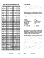
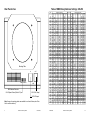
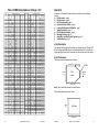
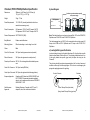
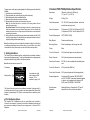
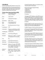
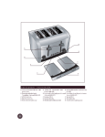
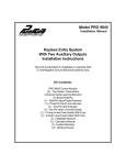
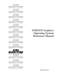
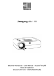
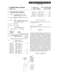
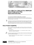
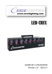
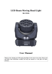
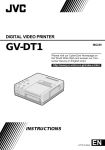
Chroma-Q Mark II User Manual
The “Digital” Version
Version 4.0 January 1999
Table of DMX Binary Address Settings 385-512
DMX
ADDRESS
NOTE:
This version of the Chroma-Q uses
a "digital" card, a binary DMX
address switch and a different
method of gel string calibration
and fixing.
Please read the manual before
using the product.
2
Version 4.0 January 1999
Chroma-Q
385
386
387
388
389
390
391
392
393
394
395
396
397
398
399
400
401
402
403
404
405
406
407
408
409
410
411
412
413
414
415
416
417
418
419
420
421
422
423
424
425
426
427
428
429
430
431
432
433
434
435
436
437
438
439
440
441
442
443
444
445
446
447
448
1
ON
ON
ON
ON
ON
ON
2
ON
ON
ON
ON
ON
ON
ON
ON
BINARYSWITCHSETTING
4
8
16
32
64
ON
ON
ON
ON
ON
ON
ON
ON
ON
ON
ON
ON
ON
ON
ON
ON
ON
ON
ON
ON
ON
ON
ON
ON
ON
ON
ON
ON
ON
ON
ON
ON
ON
ON
ON
ON
ON
ON
ON
ON
ON
ON
ON
ON
ON
ON
ON
ON
ON
ON
ON
ON
ON
ON
ON
ON
ON
ON
ON
ON
ON
ON
ON
ON
ON
ON
ON
ON
ON
ON
ON
ON
ON
ON
ON
ON
ON
ON
ON
ON
ON
ON
ON
ON
ON
ON
ON
ON
ON
ON
ON
ON
ON
ON
ON
ON
ON
ON
ON
ON
ON
ON
ON
ON
ON
ON
Chroma-Q
ON
ON
ON
ON
ON
ON
ON
ON
ON
ON
ON
ON
ON
ON
ON
ON
ON
ON
ON
ON
ON
ON
ON
ON
ON
ON
ON
ON
ON
ON
ON
ON
ON
ON
ON
ON
ON
ON
ON
ON
ON
ON
ON
ON
ON
ON
ON
ON
ON
ON
ON
ON
ON
ON
ON
ON
ON
ON
ON
ON
ON
ON
ON
ON
ON
ON
ON
ON
ON
ON
ON
ON
ON
128
256
ON
ON
ON
ON
ON
ON
ON
ON
ON
ON
ON
ON
ON
ON
ON
ON
ON
ON
ON
ON
ON
ON
ON
ON
ON
ON
ON
ON
ON
ON
ON
ON
ON
ON
ON
ON
ON
ON
ON
ON
ON
ON
ON
ON
ON
ON
ON
ON
ON
ON
ON
ON
ON
ON
ON
ON
ON
ON
ON
ON
ON
ON
ON
ON
ON
ON
ON
ON
ON
ON
ON
ON
ON
ON
ON
ON
ON
ON
ON
ON
ON
ON
ON
ON
ON
ON
ON
ON
ON
ON
ON
ON
ON
ON
ON
ON
ON
ON
ON
ON
ON
ON
ON
ON
ON
ON
ON
ON
ON
ON
ON
ON
ON
ON
ON
ON
ON
ON
ON
ON
ON
ON
ON
ON
ON
ON
ON
ON
DMX
ADDRESS 1
449
450
451
452
453
454
455
456
457
458
459
460
461
462
463
464
465
466
467
468
469
470
471
472
473
474
475
476
477
478
479
480
481
482
483
484
485
486
487
488
489
490
491
492
493
494
495
496
497
498
499
500
501
502
503
504
505
506
507
508
509
510
511
512
ON
ON
ON
ON
ON
ON
2
128
256
ON
ON
ON
ON
ON
ON
ON
ON
ON
ON
ON
ON
ON
ON
ON
ON
ON
ON
ON
ON
ON
ON
ON
ON
ON
ON
ON
ON
ON
ON
ON
ON
ON
ON
ON
ON
ON
ON
ON
ON
ON
ON
ON
ON
ON
ON
ON
ON
ON
ON
ON
ON
ON
ON
ON
ON
ON
ON
ON
ON
ON
ON
ON
ON
ON
ON
ON
ON
ON
ON
ON
ON
ON
ON
ON
ON
ON
ON
ON
ON
ON
ON
ON
ON
ON
ON
ON
ON
ON
ON
ON
ON
ON
ON
ON
ON
ON
ON
ON
ON
ON
ON
ON
ON
ON
ON
ON
ON
ON
ON
ON
ON
ON
ON
ON
ON
ON
ON
ON
ON
ON
ON
ON
ON
ON
ON
ON
ON
ON
ON
ON
ON
ON
ON
ON
ON
ON
ON
ON
ON
ON
ON
ON
ON
ON
ON
ON
ON
ON
ON
ON
ON
ON
ON
ON
ON
ON
ON
ON
ON
ON
ON
ON
ON
ON
ON
ON
ON
ON
ON
ON
ON
ON
ON
ON
ON
ON
ON
ON
ON
ON
ON
ON
ON
ON
ON
ON
ON
ON
ON
ON
ON
ON
ON
ON
ON
ON
BINARYSWITCHSETTING
4
8
16
32
64
ON
ON
ON
ON
ON
ON
ON
ON
ON
ON
ON
ON
ON
ON
ON
ON
ON
ON
ON
ON
ON
ON
ON
ON
ON
ON
ON
ON
ON
ON
ON
ON
ON
ON
ON
ON
ON
ON
ON
ON
ON
ON
ON
ON
ON
ON
ON
ON
ON
ON
ON
ON
ON
ON
ON
ON
ON
ON
ON
ON
ON
ON
ON
ON
ON
ON
ON
ON
ON
ON
ON
ON
ON
ON
ON
ON
ON
ON
ON
ON
ON
ON
ON
ON
ON
ON
ON
ON
ON
ON
ON
ON
ON
ON
ON
ON
ON
ON
ON
ON
ON
ON
ON
ON
ON
ON
Version 4.0 January 1999
ON
ON
ON
ON
ON
ON
ON
ON
ON
ON
ON
ON
ON
ON
ON
ON
ON
ON
ON
ON
ON
ON
ON
ON
ON
ON
ON
ON
ON
ON
ON
ON
ON
ON
ON
ON
ON
ON
ON
ON
ON
ON
ON
ON
ON
ON
ON
ON
ON
ON
ON
ON
ON
ON
ON
ON
ON
ON
ON
ON
ON
ON
ON
ON
ON
ON
ON
ON
ON
ON
ON
ON
19
Table of DMX Binary Address Settings 257-384
DMX
ADDRESS
257
258
259
260
261
262
263
264
265
266
267
268
269
270
271
272
273
274
275
276
277
278
279
280
281
282
283
284
285
286
287
288
289
290
291
292
293
294
295
296
297
298
299
300
301
302
303
304
305
306
307
308
309
310
311
312
313
314
315
316
317
318
319
320
18
1
ON
ON
ON
ON
ON
ON
2
ON
ON
ON
ON
ON
ON
ON
ON
ON
ON
ON
ON
ON
ON
ON
ON
ON
ON
ON
ON
ON
ON
ON
ON
ON
ON
ON
ON
ON
ON
ON
ON
ON
ON
ON
ON
ON
ON
ON
ON
ON
ON
ON
ON
ON
ON
ON
ON
ON
ON
ON
ON
ON
ON
ON
ON
ON
ON
ON
ON
ON
ON
ON
ON
ON
ON
ON
ON
ON
ON
ON
ON
ON
ON
ON
ON
ON
ON
ON
ON
ON
ON
ON
ON
ON
ON
ON
ON
ON
ON
ON
ON
ON
ON
ON
ON
ON
ON
ON
ON
ON
ON
ON
ON
ON
ON
ON
ON
ON
ON
128
ON
ON
ON
ON
BINARYSWITCHSETTING
4
8
16
32
64
ON
ON
ON
ON
ON
ON
ON
ON
ON
ON
ON
ON
ON
ON
ON
ON
ON
ON
ON
ON
ON
ON
ON
ON
ON
ON
ON
ON
ON
ON
ON
ON
ON
ON
ON
ON
ON
ON
ON
ON
ON
ON
ON
ON
ON
ON
ON
ON
ON
ON
ON
ON
ON
ON
ON
ON
ON
ON
ON
ON
ON
ON
ON
ON
ON
ON
ON
ON
ON
ON
ON
ON
ON
256
DMX
ADDRESS
ON
ON
ON
ON
ON
ON
ON
ON
ON
ON
ON
ON
ON
ON
ON
ON
ON
ON
ON
ON
ON
ON
ON
ON
ON
ON
ON
ON
ON
ON
ON
ON
ON
ON
ON
ON
ON
ON
ON
ON
ON
ON
ON
ON
ON
ON
ON
ON
ON
ON
ON
ON
ON
ON
ON
ON
ON
ON
ON
ON
ON
ON
ON
ON
321
322
323
324
325
326
327
328
329
330
331
332
333
334
335
336
337
338
339
340
341
342
343
344
345
346
347
348
349
350
351
352
353
354
355
356
357
358
359
360
361
362
363
364
365
366
367
368
369
370
371
372
373
374
375
376
377
378
379
380
381
382
383
384
1
ON
ON
ON
ON
ON
ON
2
ON
ON
ON
ON
ON
ON
ON
ON
BINARYSWITCHSETTING
4
8
16
32
64
ON
ON
ON
ON
ON
ON
ON
ON
ON
ON
ON
ON
ON
ON
ON
ON
ON
ON
ON
ON
ON
ON
ON
ON
ON
ON
ON
ON
ON
ON
ON
ON
ON
ON
ON
ON
ON
ON
ON
ON
ON
ON
ON
ON
ON
ON
ON
ON
ON
ON
ON
ON
ON
ON
ON
ON
ON
ON
ON
ON
ON
ON
ON
ON
ON
ON
ON
ON
ON
ON
ON
ON
ON
ON
ON
ON
ON
ON
ON
ON
ON
ON
ON
ON
ON
ON
ON
ON
ON
ON
ON
ON
ON
ON
ON
ON
ON
ON
ON
ON
ON
ON
ON
ON
ON
ON
Version 4.0 January 1999
ON
ON
ON
ON
ON
ON
ON
ON
ON
ON
ON
ON
ON
ON
ON
ON
ON
ON
ON
ON
ON
ON
ON
ON
ON
ON
ON
ON
ON
ON
ON
ON
ON
ON
ON
ON
ON
ON
ON
ON
ON
ON
ON
ON
ON
ON
ON
ON
ON
ON
ON
ON
ON
ON
ON
ON
ON
ON
ON
ON
ON
ON
ON
ON
ON
ON
ON
ON
ON
ON
ON
ON
Product Overview
128
256
ON
ON
ON
ON
ON
ON
ON
ON
ON
ON
ON
ON
ON
ON
ON
ON
ON
ON
ON
ON
ON
ON
ON
ON
ON
ON
ON
ON
ON
ON
ON
ON
ON
ON
ON
ON
ON
ON
ON
ON
ON
ON
ON
ON
ON
ON
ON
ON
ON
ON
ON
ON
ON
ON
ON
ON
ON
ON
ON
ON
ON
ON
ON
ON
ON
ON
ON
ON
ON
ON
ON
ON
ON
ON
ON
ON
ON
ON
ON
ON
ON
ON
ON
ON
ON
ON
ON
ON
ON
ON
ON
ON
ON
ON
ON
ON
ON
ON
ON
ON
ON
ON
ON
ON
ON
ON
ON
ON
ON
ON
ON
ON
ON
ON
ON
ON
ON
ON
ON
ON
ON
ON
ON
ON
ON
ON
ON
ON
Chroma-Q
The Chroma-Q is designed to be one of the most reliable colour changers
available. The utilization of digital circuitry and high technology composite
materials, produces an affordable colour changer which is capable of scrolling gel
strings ofvarious lengths from 2 to 16 colours.
The Chroma-Q is designed to give years of trouble free use, providing that it is
regularly adjusted and used in accordance with the instructions detailed in this
manual. If you should experience any problems which fall outside of the scope of
this manual, contact the selling dealer for further details.
If the selling dealer is unable to satisfy your servicing needs, contact A.C. Lighting
directly for full factoryservice:
Outside USA:
A.C. Lighting Ltd
Unit 3, Spearmast Industrial Park
Lane End Road, Sands
High Wycombe, Bucks
HP12 4JG England
Tel: +44 (0)1494 446000
Fax: +44 (0)1494 461024
USA:
A.C. Lighting Inc
5308 Derry Avenue, Unit R
Agoura Hills, CA 91301
USA
Tel: 1 818 707 0884
Fax: 1 818 707 0512
Product Description
The Chroma Q will read USITT DMX512 (1990) protocol, which enables individual
addressing of each unit. This allows for easy grouping of multiple units. The units
are individually addressed by setting the 10 pin binary dip switch, as displayed in
the Rear Panel Viewon page 4 and the instructions on page 8 section f.
The Chroma-Q is supplied power and control signals by means of a XLR 4-pin
input connector. The XLR 4-pin output may then be used to connect other units in
turn to the same line. Each chain line must be terminated by patching the output
from the last unit in the chain to it's corresponding return connection on the PSU /
Splitterbox, as shown in theSystem Diagramon page 7.
Note: The quantity of Chroma-Q colour changers andmaximum cable length per
distribution line is dependent upon the size of PSU / Splitterbox used and the
collective amperage draw of theunitsconnected (see page 7 for full details).
The Chroma-Q is equipped with an integral cooling fan. Each unit is also equipped
with three diagnostic LED indicators (found on the underside of the unit); showing
Power, DMX signal and DMX level (see section j - Troubleshooting on page 11 for
full details).
Chroma-Q
Version 4.0 January 1999
3
Table of DMX Binary Address Settings 129-256
Rear Panel View
DMX
ADDRESS
Mounting Plate
IN
DMX ADDRESS
DMX Address Selection
& Full Speed Control (Switch 10)
OUT
LINE
XLR 4-Pin Output
XLR 4-Pin Input
Note: A range of mounting plates are available to suit most fixtures (see Price
List for current selection).
4
Version 4.0 January 1999
Chroma-Q
129
130
131
132
133
134
135
136
137
138
139
140
141
142
143
144
145
146
147
148
149
150
151
152
153
154
155
156
157
158
159
160
161
162
163
164
165
166
167
168
169
170
171
172
173
174
175
176
177
178
179
180
181
182
183
184
185
186
187
188
189
190
191
192
1
ON
ON
ON
ON
ON
ON
2
ON
ON
ON
ON
ON
ON
ON
ON
ON
ON
ON
ON
ON
ON
ON
ON
ON
ON
ON
ON
ON
ON
ON
ON
ON
ON
ON
ON
ON
ON
ON
ON
ON
ON
ON
ON
ON
ON
ON
ON
ON
ON
ON
ON
ON
ON
ON
ON
ON
ON
ON
ON
ON
ON
ON
ON
ON
ON
ON
ON
ON
ON
ON
ON
ON
ON
ON
ON
ON
ON
ON
ON
ON
ON
ON
ON
ON
ON
ON
ON
ON
ON
ON
ON
ON
ON
ON
ON
ON
ON
ON
ON
ON
ON
ON
ON
ON
ON
ON
ON
ON
ON
ON
ON
ON
ON
ON
ON
ON
ON
Chroma-Q
128
ON
ON
ON
ON
BINARYSWITCHSETTING
4
8
16
32
64
ON
ON
ON
ON
ON
ON
ON
ON
ON
ON
ON
ON
ON
ON
ON
ON
ON
ON
ON
ON
ON
ON
ON
ON
ON
ON
ON
ON
ON
ON
ON
ON
ON
ON
ON
ON
ON
ON
ON
ON
ON
ON
ON
ON
ON
ON
ON
ON
ON
ON
ON
ON
ON
ON
ON
ON
ON
ON
ON
ON
ON
ON
ON
ON
ON
ON
ON
ON
ON
ON
ON
ON
ON
ON
ON
ON
ON
ON
ON
ON
ON
ON
ON
ON
ON
ON
ON
ON
ON
ON
ON
ON
ON
ON
ON
ON
ON
ON
ON
ON
ON
ON
ON
ON
ON
ON
ON
ON
ON
ON
ON
ON
ON
ON
ON
ON
ON
ON
ON
ON
ON
ON
ON
ON
ON
ON
ON
ON
ON
ON
ON
ON
ON
ON
ON
ON
ON
256
DMX
ADDRESS
193
194
195
196
197
198
199
200
201
202
203
204
205
206
207
208
209
210
211
212
213
214
215
216
217
218
219
220
221
222
223
224
225
226
227
228
229
230
231
232
233
234
235
236
237
238
239
240
241
242
243
244
245
246
247
248
249
250
251
252
253
254
255
256
1
ON
ON
ON
ON
ON
ON
2
128
ON
ON
ON
ON
ON
ON
ON
ON
ON
ON
ON
ON
ON
ON
ON
ON
ON
ON
ON
ON
ON
ON
ON
ON
ON
ON
ON
ON
ON
ON
ON
ON
ON
ON
ON
ON
ON
ON
ON
ON
ON
ON
ON
ON
ON
ON
ON
ON
ON
ON
ON
ON
ON
ON
ON
ON
ON
ON
ON
ON
ON
ON
ON
ON
ON
ON
ON
ON
ON
ON
ON
ON
ON
ON
ON
ON
ON
ON
ON
ON
ON
ON
ON
ON
ON
ON
ON
ON
ON
ON
ON
ON
ON
ON
ON
ON
ON
ON
ON
ON
ON
ON
ON
ON
ON
ON
ON
ON
ON
ON
ON
ON
ON
ON
ON
ON
ON
ON
ON
ON
ON
ON
ON
ON
ON
ON
ON
ON
ON
ON
ON
ON
ON
ON
BINARYSWITCHSETTING
4
8
16
32
64
ON
ON
ON
ON
ON
ON
ON
ON
ON
ON
ON
ON
ON
ON
ON
ON
ON
ON
ON
ON
ON
ON
ON
ON
ON
ON
ON
ON
ON
ON
ON
ON
ON
ON
ON
ON
ON
ON
ON
ON
ON
ON
ON
ON
ON
ON
ON
ON
ON
ON
ON
ON
ON
ON
ON
ON
ON
ON
ON
ON
ON
ON
ON
ON
ON
ON
ON
ON
ON
ON
ON
ON
ON
ON
ON
ON
ON
ON
ON
ON
ON
ON
ON
ON
ON
ON
ON
ON
ON
ON
ON
ON
ON
ON
ON
ON
ON
ON
ON
ON
ON
ON
ON
ON
ON
ON
Version 4.0 January 1999
ON
ON
ON
ON
ON
ON
ON
ON
ON
ON
ON
ON
ON
ON
ON
ON
ON
ON
ON
ON
ON
ON
ON
ON
ON
ON
ON
ON
ON
ON
ON
ON
ON
ON
ON
ON
ON
ON
ON
ON
ON
ON
ON
ON
ON
ON
ON
ON
ON
ON
ON
ON
ON
ON
ON
ON
ON
ON
ON
ON
ON
ON
ON
ON
ON
ON
ON
ON
ON
ON
ON
ON
256
ON
17
Table of DMX Binary Address Settings 1-128
DMX
ADDRESS
1
2
3
4
5
6
7
8
9
10
11
12
13
14
15
16
17
18
19
20
21
22
23
24
25
26
27
28
29
30
31
32
33
34
35
36
37
38
39
40
41
42
43
44
45
46
47
48
49
50
51
52
53
54
55
56
57
58
59
60
61
62
63
64
1
ON
ON
ON
ON
ON
ON
2
ON
ON
ON
ON
ON
ON
ON
ON
ON
ON
ON
ON
ON
ON
ON
ON
ON
ON
ON
ON
ON
ON
ON
ON
ON
ON
ON
ON
ON
ON
ON
ON
ON
ON
ON
ON
ON
ON
ON
ON
ON
ON
ON
ON
ON
ON
ON
ON
ON
ON
ON
ON
ON
ON
ON
ON
ON
ON
ON
ON
ON
ON
ON
ON
ON
ON
ON
ON
ON
ON
ON
ON
ON
ON
ON
ON
ON
ON
ON
ON
ON
ON
ON
ON
ON
ON
ON
ON
ON
ON
ON
ON
ON
ON
ON
ON
ON
ON
ON
ON
ON
ON
ON
ON
ON
ON
ON
ON
ON
ON
128
ON
ON
ON
ON
BINARYSWITCHSETTING
4
8
16
32
64
ON
ON
ON
ON
ON
ON
ON
ON
ON
ON
ON
ON
ON
ON
ON
ON
ON
ON
ON
ON
ON
ON
ON
ON
ON
ON
ON
ON
ON
ON
ON
ON
ON
ON
ON
ON
ON
ON
ON
ON
ON
ON
ON
ON
ON
ON
ON
ON
ON
ON
ON
ON
ON
ON
ON
ON
ON
ON
ON
ON
ON
ON
ON
ON
ON
ON
ON
ON
ON
ON
ON
ON
ON
256
DMX
ADDRESS
65
66
67
68
69
70
71
72
73
74
75
76
77
78
79
80
81
82
83
84
85
86
87
88
89
90
91
92
93
94
95
96
97
98
99
100
101
102
103
104
105
106
107
108
109
110
111
112
113
114
115
116
117
118
119
120
121
122
123
124
125
126
127
128
1
ON
ON
ON
ON
ON
ON
2
ON
ON
ON
ON
ON
ON
ON
ON
BINARYSWITCHSETTING
4
8
16
32
64
ON
ON
ON
ON
ON
ON
ON
ON
ON
ON
ON
ON
ON
ON
ON
ON
ON
ON
ON
ON
ON
ON
ON
ON
ON
ON
ON
ON
ON
ON
ON
ON
ON
ON
ON
ON
ON
ON
ON
ON
ON
ON
ON
ON
ON
ON
ON
ON
ON
ON
ON
ON
ON
ON
ON
ON
ON
ON
ON
ON
ON
ON
ON
ON
ON
ON
ON
ON
ON
ON
ON
ON
ON
ON
ON
ON
ON
ON
ON
ON
ON
ON
ON
ON
ON
ON
ON
ON
ON
ON
ON
ON
ON
ON
ON
ON
ON
ON
ON
ON
ON
ON
ON
ON
ON
ON
ON
ON
ON
ON
ON
ON
ON
ON
ON
ON
ON
ON
ON
ON
ON
ON
ON
ON
ON
ON
ON
ON
ON
ON
ON
ON
ON
ON
ON
ON
ON
ON
ON
ON
ON
ON
ON
ON
ON
ON
ON
ON
ON
ON
ON
ON
ON
ON
ON
ON
ON
ON
ON
ON
ON
ON
ON
ON
ON
ON
ON
ON
ON
ON
ON
ON
ON
ON
ON
ON
ON
ON
Operation
128
256
ON
ON
ON
ON
ON
ON
ON
ON
ON
ON
ON
ON
ON
ON
ON
ON
ON
ON
ON
ON
ON
ON
ON
ON
ON
ON
ON
ON
ON
ON
ON
ON
ON
ON
ON
ON
ON
ON
ON
ON
ON
ON
ON
ON
ON
ON
ON
ON
ON
ON
ON
ON
ON
ON
ON
ON
ON
ON
ON
ON
ON
ON
ON
A summary of Chroma-Q's operations has been divided into the following
sections:
a) Gel Description - page 5
b) Gel Dimensions - page 5
c) Gel String A ssembly - page 6
d) Control and Power Cables - page 6
e) Loading Gel Strings and Calibration - page 7
f)
Setting the Address - page 8
g) PSU / Splitterbox Options - page 8
h) Mounting Position - page 10
i)
Using Mark I and Mark II Units Together - page 10
j)
Troubleshooting - page 11
a) Gel Description
The standard gel string consists of a leader, gel frames and a tail. Procolor HT+,
Rosco Supergel and GAMcolor are the recommended brands. The leader and
tail are taped to gel tabs which are inserted into the slots on each of the rollers.
b) Gel Dimensions
The leader and tail dimensions are as follows:
455mm (18.2“)
178mm
(7“)
115mm (4.6“)
Tail &
Leader
Gel Tab
60mm
(2.4“)
570mm (22.8“)
Note: The tail and leader include the first/last frame.
The gel frame dimensions are as follows:
178mm
(7“)
Gel Frame
ON
255mm (10“)
16
Version 4.0 January 1999
Chroma-Q
Chroma-Q
Version 4.0 January 1999
5
c) Gel StringAssembly
To join a leader, tail, gel and tab together, a high temperature, clear gel tape is
recommended (see Product Ordering List on page15).
To join leaderandtail torollers, gel tabs are required (see ProductOrderingListon page
15).
Thecompleted string should look likethis:
Grey Knob
Black Knob
Take-up Roller
(Spring Loaded)
Gel
Tab
Leader &
1st
Colour
Frame
Take-up Roller
(Fixed)
2nd
Colour
Frame
15th
Colour
Frame
16th
Colour & Tail End
Frame
Gel
Tab
approx. 4775mm (188“)
Note: A range of completed gel strings are available (see Product Ordering List on
page 15). Custom gel strings are available upon request. Contact the selling dealer for
details.
When ordering gel strings please ensure you statewhich type ofChroma-Q you require
themfor,either an “original”Mark I Chroma-Q,ortheMarkII “Digital”Chroma-Q.
Note: Gel strings prepared for the Mark II Chroma-Q can be used in a Mark I unit. Todo
this remove the pre-fixed metal gel tab (but donot throw thisaway as it may be useful at
a later date) and simplytapethegeltotheMarkI (non-slotted) take upreels.
d) Control and Power cables
Only genuine Tourflex Data Safe cable is recommended for use with the Chroma-Q
colour changing System (see Product Ordering List on page15).
The Chroma-Q utilizes an XLR 4-pin cable system. This is used for power and data
transfer. Pins 1 and 4 serve as 24VDC power. Pins 2 and 3 are used for USITT 1990
DMX512control protocol.
Note: It is very important to ensure that the drain wire from the cable shield is connected
to both connectorcases.
Product Ordering List
CQ1/D
MP1
MP2
MP3
MP4
MP5
MP6
PS08
PS18/2
GST16
GST16/D
GSR16
GSR16/D
GTI
ST
Chroma-Q Digital Colour Changer
Mounting Plate for Par 64, aperture 165mm
Mounting Plate for Source 4 Par
Mounting Plate for Source 4 / Shakespeare
Mounting Plate for 6" Leko / 360Q, aperture 190mm
Mounting Plate 185mm × 185mm
Mounting Plate 254mm × 254mm, aperture 190mm
6.5 Amp PSU / Splitterbox
13 Amp PSU / Splitterbox
16 frame "Theatre" Gel String for original Chroma-Q
16 frame "Theatre" Gel String for digital Chroma-Q
16 frame "Rock & Roll" Gel String for original Chroma-Q
16 frame "Rock & Roll" Gel String for digital Chroma-Q
Gel tabs
High Temperature Clear Tape
Chroma-Q Data Safe Cables
CQC3
CQC5
CQC10
CQC25
CQC50
CQC100
1m / 3ft Chroma-Q Colour Changer Cable
1.5m / 5ft Chroma-Q Colour Changer Cable
3m / 10ft Chroma-Q Colour Changer Cable
7.5m / 25ft Chroma-Q Colour Changer Cable
15m / 50ft Chroma-Q Colour Changer Cable
30m / 100ft Chroma-Q Colour Changer Cable
DMX Data Safe Cables
DS10
DS25
DS50
DS100
TP
3m / 10ft Data Safe 5 pin DMX Cable
7.5m / 25ft Data Safe 5 pin DMX Cable
15m / 50ft Data Safe 5 pin DMX Cable
30m / 100ft Data Safe 5 pin DMX Cable
5 pin DMX Termination Plug
When assemblingXLR4-pin cables, heat shrink should b e used on each individual pin
to prevent short circuits.
Note: Damage will occur if power connectionsshort-circuit to control protocol or ground
shield connections.
The pins are wired one to one, in the following format:
Pin
1
2
3
4
Chassis
6
Function
0V DC
Control Data Minus
Control Data Plus
Plus 24V DC
Ground Bonding
Version 4.0 January 1999
Chroma-Q
Chroma-Q
Version 4.0 January 1999
15
Chroma-Q PS18/2 PSU/Splitterbox Specification
Dimensions:
300mm (w) x 68.75mm (h) x 281.25mm (d)
12" (w) x 2.75" (h) x 11.25" (d)
Weight:
3.3kg / 7.3 lbs
Power Requirements:
System Diagram
Continue up to the maximum capacity
of the power supply
PSU/Splitterbox
115 / 230V AC (internally switchable, isolate from
mains before removing cover)
DMX In
Return
Mains Power In
Out
IN
Power Consumption:
6.4 Amperes at 115V AC with 13 Amps at 24V DC
3.2 Amperes at 230V AC with 13 Amps at 24V DC
Powder-coated Aluminium
Mounting Options:
Either freestanding or can be hung from a bolt
Colour:
Black
Circuit Out Connector:
XLR 4-pin female (power and control protocol)
Return Connector:
XLR 4-pin male (power and control protocol)
OUT
LINE
IN
DMXADDRESS
OUT
IN
DMXADDRESS
LINE
OUT
LINE
Note: Total cable length per circuit must not exceed 60m / 200' on the PS08 PSU /
Splitterbox and 105m / 350' on the PS18/2 PSU / Splitterbox.
Protocol Requirements: USITT DMX512 (1990)
Body Material:
DMXADDRESS
The total amperage draw, at 24V DC, of the connected units must not exceed 6.5
Amps on the PS08 unit PSU / Splitterbox and 13 Amps on the PS18/2 PSU /
Splitterbox.
e) LoadingGelStringsandCalibration
In order to load gel strings, clip the gel tab after frame 16 to the fixed take-up roller
(black knob) and hand roll the scroll on to it. Then clip the gel tab before frame 1 on
to the spring loaded take-up roller (grey knob) and place the string into the
Chroma-Q.
Power Input Connector: IEC 10A, UL rated supplied with detachable power
cord
Control Out Connector: XLR 5-pin female (DMX link)
The gel string should be positioned approximately at the first colour frame and
inserted as shown by the following diagram. This is done to avoid trapping the
spring when applyingtension to the gel string.
Control Input Connector: XLR 5-pin male (protected with clamping diodes)
European Approvals:
North American
Approvals:
Counter Clockwise
Complies with EU directives: EMC 89/336/EEC and
LVD 73/23/EEC. Harmonized standards applied in
order to verify compliance with directives: EN 50081-1
& EN 50082-1: 1992
Clockwise
Gel String Leader & 1st Colour
Radiated Emissions: Complies with FCC part 15,
subpart B, class A for unintentional radiators
Fixed Take-up Roller (black knob)
Spring Loaded Take-up Roller (grey knob)
14
Version 4.0 January 1999
Chroma-Q
Chroma-Q
Version 4.0 January 1999 1998
7
To apply tension to the gel string being loaded, the following procedure should be
followed:
Chroma-Q PS08 PSU/Splitterbox Specification
Dimensions:
185mm (w) x 65mm (h) x 240mm (d)
7¼" (w) x 2½ " (h) x 9½" (d)
Weight:
2.05kg / 4.5lb
Power Requirements:
115 / 230 V AC (internally switchable - isolate from
mains before removing cover)
Power Consumption:
3.2 Amperes at 115VAC with 6.5 Amps at 24V DC
1.6 Amperes at 230VAC with 6.5 Amps at 24V DC
Protocol Requirements:
USITT DMX512 (1990)
Body Material:
Powder-coated Aluminum
Note: The slotted takeuprollerson the Mark II canbefitted to theMark I unit. We offer a
cost effective part exchange service for these rollers. If you w ould like to fit your Mark I
unitswithMark II rollers, please contact our sales staff for advice and a quotation.
Mounting Options:
Either freestanding or can be hung from a bolt
Colour:
Black
f) Setting theAddress
Circuit Out Connector:
XLR 4-pin female (power and control protocol)
The Chroma-Q can be addressed easily by setting the binary dip switches located on
therear panel (seediagrampage 4).To set your desiredaddress,move theappropriate
switches to either the on (up) position o r the off(down) position.
Return Connector:
XLR 4-pin male (power and control protocol)
Power Input Connector:
IEC 10A, UL rated, supplied with detachable power
cord
Control Out Connector:
XLR 5-pin female (DMX link)
Control Input Connector:
XLR 5-pin male (protected with clamping diodes)
European Approvals:
Complies with EU directives: EMC 89/336/EEC
and LVD 73/23/EEC. Harmonized standards applied
in order to verify compliance with directives: EN
55022 (class B), EN 50082-1 & EN 60950
North American
Approvals:
Radiated Emissions: Complies with FCC part 15,
subpart B, class A for unintentional radiators
1)
2)
3)
4)
5)
Holdfixedroller (roller with blackknob).
Lift spring-loaded roller (roller with grey knob) until itrotates freely.
Rotate spring-loaded roller clockwisewhilelifted.
Replace spring-loadedrollersecurely on shaft base.
Repeat procedureas required, until excess slack isremoved
Note: No more than three turns or revolutions of the spring loaded roller are
required to tension the gel.
Do not Over Tension. This will cause damage to the unit, ie broken springs, bent
shafts and premature wear on mechanical components. It will also increase the
ambient noise level of the unit. Always ensure that fixed roller does not rotate while
completing this procedure.
6) Power upthe unit and a selfcalibration procedure will be completed to set the 100%
and 0% gel string settings (It is advisable tohave control protocol at the zerolevel to
verifythegel stringhasbeenloaded properly).
Note: All switches in the down position is 0.
Forexample:
The DMX address is equal to the
sum of the selected switches.
Switch position =
For example DMX ADDR. 327=
ON
OFF
A complete chart of dip
switch settings for DMX
channels 1-511 is
available on pages 16-19.
To reduce units maximum motor
speed turn Dip switch # 10 on
The Chroma-Q can also be set to a second default motor speed. By moving switch 10
on the binary dip switch to the on (up) positon, the inherent speed of the Chroma-Q will
decrease by approximately 50% (ideal for environments that are particularly noise
sensitive).
g) PSU / Splitterbox Options
The Chroma-Q PSU / Splitterboxes are the only units suitable to be connected to
Chroma-Q colour changers. Connection to other units will invalidate the warranty and
may cause serious damage to Chroma-Q colour changers and / or Chroma-Q PSU /
Splitterbox.
8
Version 4.0 January 1999
Chroma-Q
Chroma-Q
Version 4.0 January 1999
13
Limited Warranty
Your Chroma-Q colour changers and PSU / Splitterbox are covered by a 12 month
warranty against defects in manufacture. T he warranty covers parts and labour but
excludes the cost of freight. In thecaseofany warranty claims, please contact your
selling dealer. If the selling dealer is unable to assist you, please contact A.C.
Lighting directly at theappropriate address as detailed on page 3.
Chroma-Q Colour Changer Specification (CQ1/D)
Dimensions:
285mm (w) x 295mm (h) x 89mm (d)
5
11¼" (w) x 11 /8" (h) x 3 ½"(d)
Aperture:
171mm / 6 ¾" diameter
Weight:
2.04kg / 4.5lb (without mounting frame)
Gel FrameCapacity:
between 2 - 16 frames
Speed:
Speed 2:
1.5 seconds with dip switch 10 toOff
3.2 seconds with dip switch 10 toOn
Address:
10 pin binary dipswitch address up to 512 channels
Power Requirements:
24VDC
Power Consumption:
0.9 Amperes peak at 24V DC with dip switch 10 toOn
1.3 Amperes peak at 24V DC with dip switch 10 toOff
Protocol Requirements:
USITT DMX512(1990)
BodyMaterial:
UL94V0 rated reinforced PBT compound
Mounting Plate:
Mounting plates are available to suit numerous
fixtures (see separate price list for current selection)
Colour:
Black
Input Connector:
XLR 4-pin male (power and control protocol)
Output Connector:
XLR 4-pin female (power and control protocol)
EuropeanApprovals:
Complies with EU directives: EMC 89/336/EEC
Class A. Harmonized standards applied in order to
v e r i f y c o m p l i a n c e w i t h d i r e c t i v e s : EN
56022:1994, EN50082-1: 1992 & EN 60950
NorthAmerican
Approvals:
Radiated Emissions: Complies with FCC part 15,
subpart B, class A for unintentional radiators.
Low Voltage Directive: Complies with CSA 22.2
950,UL1950
12
Version 4.0 January 1999
The Chroma-Q PSU / Splitterbox is available in 2 sizes: One suitable for 6.5 Amps
DCand the other suitable for 13Amps DC total load.
Each Chroma-QPSU/ Splitterbox is equipped with thefollowing:
1) DMX input and thru sockets
2) DMX data indicator
3) Mainspower indicator
4) XLR 4-pin output sockets
5) XLR 4-pin return sockets
6) AC mains input
The basic purpose of the PSU / Splitterbox is to combine the DMX control signal
and the 24VDC power into individual lines. There are separate circuit outputs for
distribution on each PSU / Splitterbox, each capable of supplying power and data
for Chroma-Q colour changers. The maximum total cable length for each output
circuit is 60M / 200' on the PS08 PSU / Splitterbox and 105M / 350' on the PS18/2
PSU / Splitterbox.
All outputs are independent of one another, and each line has it's own return. The
purpose of the return socket is to maintain a constant voltage level across all units
on each line, to prevent line lossand toprovide DMX signal termination.
The PS08 PSU / Splitterbox has two Chroma-Q circuits and produces 24VDC at
6.5 Amps maximu m output.Thismeans a total of7 Chroma-Qcolour changers can
be powered through a single PS08 PSU / Splitterbox. The power consumption is
approximately 3.2 Amps at 115VAC.
To change the operating voltage on the PS08 PSU / Splitterbox, first isolate the unit
from the mains supply, then remove the main body cover by unscrewing the four
screws on the side of the cover. Set the voltage selection switch to the desired
setting and refit the cover using the four screws.
The PS18/2 PSU / Splitterbox has twoChroma-Q circuits and produces 24VDC at
13 Amps maximum output. This means that a total of 14 Chroma-Q colour
changers can be powered through a single PS18/2 PSU / Splitterbox. The power
consumption is approximately 6.4Amps at 115VAC.
Chroma-Q
To change the operating voltage on the PS18/2 PSU / Splitterbox, first isolate the
unit from the mains supply, then remove the main body cover by unscrewing the
four screws on the side of the cover. Set the voltage selection switches (two) to the
desired settingand refit the cover using the four screws.
Chroma-Q
Version 4.0 January 1999
9
h) Mounting Position
j) Troubleshooting
The Chroma-Q is designed to be mounted in an upright position with the base of
the unit below the fixture. Do notmount in an inverted position with the base of the
unit above the fixture, as the effect of the rising heat from the fixture may cause gel
string damage.
Troubleshooting of the Chroma-Q is aided by the indications provided by the 3
diagnosticLED's located on theunderside of the Chroma-Q.
Always ensure that the Chroma-Q is powered up before the fixture and that you
follow the reverse procedure at the end of the show. Failure to do so may cause gel
string damage.
Thissection is a guide to solving common problems:
i) Using Mark I and Mark II Units Together
Mark I and Mark II units can easily be used on the same “show”. If doing this,
calibrate your Mark I units first and last frames to the same frames of the Mark II
units.
All troubleshooting procedures shouldbeginwithaLEDcheck.
Symptom
Possible Cause
Solution
All Chroma-Qs show no
power indicator (RedLED).
24V DC power supply is not
providing power to ChromaQ.
Check if mains power is on
andred 24VDCLEDis on.
Single Chroma-Q power
indicatoris off (Red LED).
4-pin XLR cable has broken
connection.
Replace 4-pin XLR cable.
Power indicator light in
flashing.(Red LED).
Gel string is jammed.
Readjust or replace faulty
gel stringand / or turn p ower
off and then on again. This
will reset the unit.
Chroma-Q has dim power
light ( RedLED).
Voltage has dropped below
acceptable level.
Check that the return line
has been installed. Check
maximum cable length has
notbeen exceeded.
DMX indicator o n a l l
Chroma-Q are off (Green
LED).
No DMX is present at the
Splitterbox.
Check that theDMXcableis
properly connected to DMX
input on the Splitterbox.
Check that DMX indicator
l i g h t , located on the
Splitterbox , i s on.
DMX indicator light on one
group of Chroma-Q's are off
(Green LED).
One output of the
Splitterbox has failed.
Faulty XLR 4-pin cable at
Splitterbox output.
Call selling dealer.
Level indicator does not
respond to DMX control
signal (Yellow LED).
Improper address.
Reassign unit addressing.
Level indication changes
intensity, b ut gel string does
notmove(Yellow LED).
Mechanical failure.
Call selling dealer.
Test cables.
Note: A high percentage of problems are caused by corrupt DMX control protocol.
We highly recommend the use of genuine Tourflex Data Safe cables for all
Chroma-Qcolour changer and DMX control protocol cables.
10
Version 4.0 January 1999
Chroma-Q
Chroma-Q
Version 4.0 January 1999
11