1
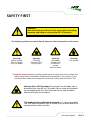
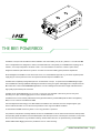
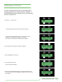
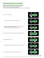
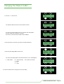
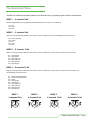
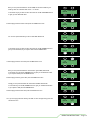
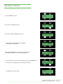
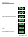
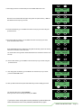
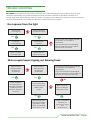
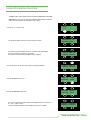
User Manual BB1 POWERBOX BB1 & POWERBOX contents INTRO, RIGGING, SET UP & MODES SAFETY FIRST THE BB1 RIGGING SET UP IDENTIFY DIMMER CURVE ADDRESS MODE MODES page 3 page 5 page 6 page 7 page 8 page 9 page 10 page 11 OPERATING INSTRUCTIONS STAND ALONE FUNCTIONS CREATING A MEMORY STORING A MEMORY RECALLING A MEMORY PROGRAMING A CHASE page 12 page 12 page 14 page 15 page 16 THE TECHNICAL STUFF TECHNICAL SPECIFICATIONS UNIT DIMENSIONS DRAWING TROUBLE SHOOTING INTERNAL INFORMATION page 18 page 19 page 20 page 22 APPENDICES APPENDIX 1 APPENDIX 2 ROHS COMPLIANCE AND WEEE DIRECTIVE INSTRUCTIONS SERVICE CONTACT DETAILS page 24 page 25 OPERATING INSTRUCTIONS - Page 2 SAFETY FIRST WARNING! WARNING! Read safety precautions in this section before Read thethe safety precautions in this section before installing, installing, powering, operating or servicing the BB4 2 powering, operating or servicing the BB1 & Powerbox The following symbols are used to identify important safety information in this manual: Warning! Safety hazard. Risk of severe injury or death Warning! LED light emission. Risk of eye injury Warning! Hazardous voltage. Risk of lethal or severe electric shock Warning! Fire hazard ! Read this manual before installing, powering or servicing the fixture, follow the safety precautions listed below and observe all warnings in this manual. If you have questions about how to operate the fixture safely, please contact I-Pix. Warning! Class 2M LED product. Do not look into the beam from a distance of less than 40 cm (16 inches). Do not stare into the beam for extended periods at a short distance. Do not view the beam directly with optical instruments. This product is for professional use only. It is not for household use. This product presents risks of severe injury or death due to fire hazards, electric shock and falls. BB4 USERSMANUAL MANUAL - PAGE 3 BB2 USERS PROTECTION FROM ELECTRIC SHOCK Shut down power to the entire installation at the building’s main power distribution board and lock out power (by removing the fuse for example) before carrying out any installation or maintenance work. Disconnect the fixture from AC power before removing or installing any cover or part and when not in use. Disconnect the fixture from AC power before removing or changing the fuse. Always ground (earth) the fixture electrically. Use only a source of AC power that complies with local building and electrical codes and has both overload and ground-fault (earth-fault) protection. Connect this fixture to AC power either using the supplied power cable or via 3- conductor cable that is rated minimum 20 amp, hard usage. Suitable cable types include ST, SJT, STW, SEO, SEOW and STO. The voltage and frequency at the power outlet are the same as the voltage and frequency applied to the power inlet. Only connect devices to the power outlet that accept this voltage & frequency. Before using the fixture, check that all power distribution equipment and cables are in perfect condition and rated for the current requirements of all connected devices. Do not use the fixture if the power cable or power plug are in any way damaged, defective or wet, or if they show signs of overheating. PROTECTION FROM FIRE Do not attempt to bypass thermostatic switches or fuses. Replace defective fuses with ones of the specified type and rating only. Provide a minimum clearance of 0.1 m (4 in.) around fans and air vents. Do not modify the fixture Apart from I-PIX accessories do not stick filters, masks or other materials directly onto the light. PROTECTION FROM INJURY when Do not hang fixtures from each other. Use two OMEGA clamps per fixture or I-PIXrigging SINGLE or DOUBLE YOLKS when suspending. horizontally. When suspending the fixture, ensure that the structure and all hardware used can hold at least 10 times the weight of all devices suspended from them. Use two secondary attachments (such as a safety cable) to secure each fixture. Secondary attachments must be able to hold at least 10 times the weight of all devices suspended from them and must be installed as described in this manual. Check that all external covers and rigging hardware are securely fastened. Block access below the work area and work from a stable platform whenever installing, servicing or moving the fixture. The LED emission presents a hazard to eyesight at a distance of 4 - 40 cm (1.6 -16 inches) when the eye is exposed to the beam for longer than 0.25 seconds. Do not look at LEDs from a distance of less than 40 cm (1 ft. 4 in.) without suitable protective eye wear. Do not look at LEDs with magnifiers or similar optical instruments that may concentrate the light output. BB4 USERSMANUAL MANUAL - PAGE 4 BB2 USERS THE BB1 POWERBOX The BB1 is a compact and versatile instrument available in four beam widths ( 20°,35°,45° ) and the 10° narrow beam BB1 This is a single LED fixture, designed for outdoor and submersible use to 2m ( IP 68 ). It is an RDM device requiring just 15 Volts DC, at 3.6 amps. Full power is 30 Watts at 240 v. For entertainment use there are a choice of power boxes, designed to facilitate quick cable hook up, with an on board user interface enabling quick parameter adjustments. All the intelligence of the BB1 is in the head of the fixture. for fixed instillation purposes any 15V 5A DC regulated power supply may be used to power the fixture in conjunction with data input that is DMX 512A. The BB1 offers completely homogenized optics for the smoothest of output It's powerful custom RGB LED light engine has incredible colour mixing capabilities including the effortless sourcing of tungsten and daylight colour temperatures.The BB1 comes with a self contained RDM/DMX digital drive. It can be submerged and comes with a single cable fitted with a high quality 5-pin weatherproof connection The BB1 can be used independently, e.g. as a truss or a set toner. It is fitted with a dual set of yokes for easy floor mounting or for quick, tool free rigging onto a truss or metalwork in the air. The BB1 fixtures can be remotely addressed and configured with industry standard RDM (remote device management) DMX, or run as a slave on standard USITT DMX. i-Pix new Digital Drive technology is over 90% efficient and delivers even smoother control of the light engines, right down to lowest intensities. True 16 bit control expands the colour range from millions to billions. In entertainment the BB1 is driven by either a 4 or 6 way powerbox or powerbar. The powerbox and powerbar remotely address the fixtures via RDM DMX or use the onboard user interface which provides both operating mode and address control.Combined power and data input ensures a weatherproof connection, so the power distro can be used outdoors in any orientation.A battery and data inlet connects to an optional battery and show DMX wireless DMX module. Rigging mounts are provided for truss or frame mounting. OPERATING INSTRUCTIONS - Page 5 Rigging a BB1 Powerbox To rig a Powerbox use the OMEGA bracket supplied with the box. This would have your clamp of choice bolted on to it. First place the camloc pins in the receptacles either on the top or the bottom of the powerbox with the levers facing out so that a quarter turn clockwise will have them facing in alternate directions as shown. Always secure the Powerbox to the truss,pipe e.t.c. with a safety bond, attached to the box through any of the safety points shown in green. OPERATING INSTRUCTIONS - Page 6 Identifying A Fixture In order to determine wich fixture you are addressing or changing the mode of, it it may be usefull to “ Identify “ it. Once Identified the fixture will flash at full until the Identify function is switched off. 1 Press the 1 - 4 button once. MENU 1-4 PRESS The powerbox will now search out all connected fixtures. Any fixture connected will be shown as an address and mode beside the port number it is attached to - 2001 M2. Ports with no attached fixtures will be shown as EMPTY. SEARCHING FOR DEVICES PORT 1 1 empty 2001 M2 3 empty 4 empty PRESS 2 Press the button of the fixture you wish to Identify. 1 empty 2001 M2 3 empty 4 empty 3 Press the IDENTIFY button once. PSNLTY IDENTIFY ADDR MORE PRESS PRESS 4 Press the ON button once. The fixture will start flashing. ON OFF PRESS 5 Once you have Identified the fixture, press the fixture button once ( the one with the star ) press IDENTIFY then OFF and the fixture will stop flashing 1 empty 2001❇M2 3 empty 4 empty OPERATING INSTRUCTIONS - Page 7 Changing Dimming Curve of A BB 1 The BB1 has the option of using either one of two dimmer curves. Linear - the output increases directly with the DMX input. Enhanced - the first 10% of the output is directly controlled over the first 50% of the DMX input. 1 Press the 1 - 4 button once. MENU 1-4 PRESS The powerbox will now search out all connected fixtures. Any fixture connected will be shown as an address and mode beside the port number it is attached to - 2001 M2. Ports with no attached fixtures will be shown as EMPTY. SEARCHING FOR DEVICES PORT 1 1 empty 2001 M2 3 empty 4 empty PRESS 2 Press the button of the fixture you wish to change the Dimmer curve of. 1 empty 2001 M2 3 empty 4 empty 3 Press the MORE button once. PSNLTY IDENTIFY ADDR MORE PRESS CURVE L shows the dimming curve currently in use - L linear, E enhanced RUNTIME CURVE L softver EXIT PRESS 4 Press the CURVE button once to change the dimming curve. RUNTIME CURVE L softver EXIT OPERATING INSTRUCTIONS - Page 8 Addressing the BB 1 1 Press the 1 - 4 button once. MENU 1-4 PRESS The powerbox will now search out all connected fixtures. Any fixture connected will be shown as an address and mode beside the port number it is attached to - 2001 M2. Ports with no attached fixtures will be shown as EMPTY. SEARCHING FOR DEVICES PORT 1 1 empty 2001 M2 3 empty 4 empty PRESS 2 Press the button of the fixture you wish to Address. 1 empty 2001 M2 3 empty 4 empty PRESS 3 Press the address ADDR button once. 4 Use the 1 10 and 100 buttons to create the desired address. PSNLTY IDENTIFY ADDR MORE 100 10 ADDR 021 1 PRESS OPERATING INSTRUCTIONS - Page 9 Changing The Mode of A BB 1 MENU 1-4 1 Press the 1 - 4 button once. PRESS The powerbox will now search out all connected fixtures. Any fixture connected will be shown as an address and mode beside the port number it is attached to - 2001 M2. Ports with no attached fixtures will be shown as EMPTY. SEARCHING FOR DEVICES PORT 1 1 empty 2001 M2 3 empty 4 empty PRESS 2 Press the button of the fixture you wish to change the Mode of. 1 empty 2001 M2 3 empty 4 empty PRESS PSNLTY IDENTIFY 3 Press the personality PSNLTY button once ADDR MORE The fixture personality which is the mode the fixture is in, is now displayed 2 mode number M master intensity S strobe R red G green 5CH number of channels 4 Press the mode button to change the fixture personality PERSONALITY 2 MSRGB 5CH PERSONALITY 3 RGB 6CH PRESS OPERATING INSTRUCTIONS - Page 10 h a greater Ideal for use with mediaIdeal servers, for with use with a greater media servers, with a greater cell with a strobe and acell highwith resolution a strobemaster and a high resolution master cell with a strobe and a high cell with res resolution over the colours. resolution over the colours. MASTER MASTER MASTER MASTER MASTER MASTER MASTER MASTER MASTER MASTER MASTER MASTER STROBE STROBE STROBE MASTER MASTER MASTER MASTER MASTER MASTER STROBE STROBE STROBE intensity having overall intensity control over having all 4overall cells. control over all 4 cells. intensity having overall control intensito INTENSITY INTENSITY INTENSITY with its ownEach red cell can be individually Eachcoloured cell can be with individually its own red coloured with its ownCHANNEL red INTENSITY INTENSITY INTENSITY INTENSITY INTENSITY INTENSITY INTENSITY INTENSITY INTENSIT CHANNEL CHANNEL INTENSITY INTENSITY INTENSITY INTENSITY INTENSITY INTENSITY CHANNEL CHANNEL CHANNEL en each cell isgreen blue channel. (most green useful blue when channel. each (most cell is useful when each cell is ch1 -The master intensity high ch1 byte master all cells intensity high byte all cells ch1 - master intensity high ch1byte -m Operating Modes patched individually -6ch) patched individually -6ch) MASTER MASTER MASTER MASTER MASTER MASTER STROBE STROBE STROBE ch2 - master intensity low ch2byte - master all cells intensity low byte all cells ch2 - master intensity low ch2 byte - ma MODES MODES MODES AGRAPHICAL A A GRAPHICAL GRAPHICAL MODES MODES MODES AOVERVIEW A OVERVIEW A GRAPHICAL OVERVIEW GRAPHICAL OVERVIEW GRAPHICAL OVERVIEW OVERVIEW OVERVIEW MODES MODES MODES A A G GRAPHICAL GRAPHICAL MODES MODES MODES AAAOVERVIEW GRAPHICAL OVERVIEW OVERVIEW OVERVIEW OVERVIEW OVERVIEW MODES MODES MODES AAAA GRAPHICAL GRAPHICAL MODES MODES MODES AAOVER AOVE GRA OV OV GR MODES MODES A GRAPHICAL AGRAPHICAL GRAPHICAL GRAPHICAL MODES MODES A OVERVIEW GRAPHICAL A OVERVIEW GRAPHICAL OVERVIEW GRAPHICAL OVERVIEW OVERVIEW OVERVIEW MODES MODES A A DES ES SSAAAA A GRAPHICAL GRAPHICAL GRAPHICAL MODES MODES A OVERVIEW A GRAPHICAL OVERVIEW GRAPHICAL OVERVIEW GRAPHICAL OVERVIEW OVERVIEW MODES MODES A GRAPHICAL GRAPHICAL GRAPHICAL MODES MODES A A GR OV OV GA GG ES SES AAA GRAPHICAL GRAPHICAL GRAPHICAL MODES MODES MODES AAOVERVIEW A GRAPHICAL OVERVIEW GRAPHICAL OVERVIEW GRAPHICAL OVERVIEW OVERVIEW OVERVIEW MODES MODES MODES AAA GRAPHICAL GRAPHICAL GRAPHICAL MODES MODES MODES AOVE AA GR OV OV GR G INTENSITY INTENSITY INTENSITY INTENSITY INTENSITY INTENSITY CHANNEL CHANNEL CHANNEL ch3 - strobe all cells ch3 - strobe all cells ch3 - strobe all cells ch3 - str ch1 - red high byte cell 1ch1 - red high byte cell 1 ch4 -The redBB1 high byte cell ch4 1 - red high byte cell 1 ch4 - red high byte cell 1ch4 - re 4 different modes to suit ch2 has - red low byteoperating cell 1 ch2 - red lowdifferent byte celluses, 1 programing styles and dmx configurations ch5 - red low byte cell 1ch5 - red low byte cell 1 ch5 - red low byte cell 1 ch5 - re ch3 green high byte cell ch3 1 green high byte cell 1 - 3 byte channels ch6 -MODE green1high cell ch618-bit green high byte cell 1 ch6 - green high byte cellch6 1 - gr ch4 - green low byte cellch4 1 - green low byte cell 1 most simple, ideal for fast limited line space ch7 -The green low byte cell ch7 1programing - greenorlow byte cell and 1 as a node on a media server. ch7 - green low byte cellch7 1 - gr ch5 - blue high byteMODE cell ch5 1 86 - 15 blue high byte cell 1 hannel 16 bit MODE - 12 24 channel 27 channel 1616 bitbit MODE 8 - 15 27 channel 16 bit ch8 blue high byte cell ch8 - blue high byte 1414 - blM ch1 -high red Mode Mode 1111- cell Mode Mode Mode 23low 11byte Mode Mode Mode Mode 23 32 2 3 3 Mode Mode Mode Mode Mode 3 Mode Mode 3cell 1 3 451 15ch8 Mode Mode 5 11 ch8 - blue Mode Mode Mode Mode Mode 2byte 1Mode 21 2 12 1cell Mode Mode Mode Mode Mode 2Mode 3 23 233 Mode Mode Mode Mode Mode Mode 3Mode 3Mode 34 134 14 434 Mode Mode Mode Mode Mode Mode 2 2 4 1 2 4 15 1 43 Mode Mode Mode Mode Mode Mode Mode 212122 211 cell Mode Mode 22 23 Mode Mode Mode 35 Mode 3 45 414 ch6 -Mode blue low 2Mode ch6 -Mode blue 2Mode Mode Mode Mode Mode Mode Mode Mode 2 2 111byte Mode Mode Mode Mode 2 3 2 2 Mode Mode Mode Mode 3 Mode Mode 31 1 4 1 Mode Mode Mode Mode Mode 2 4 2 1 2 4 4 1 ch2 green ch9 - blue low byte cell ch9 1 MODE -High blue low byte cell 1servers, ch9MODE - blue low byte cell 1ch9 -each bl resolution colour control overbit each individual High resolution colour control overbit 15 12 15 channel 16 bit MODE 6 24 channel 16 bit 8 27 channel 16 8 27 channel 16 dia servers, with a greater Ideal for use with media with a greater ch7 - red high byte cell cellwith 2ch7 - red cell master 2 ch3 - blue a strobe andhigh a highbyte resolution cell with a strobe and a high resolution m ch10 - red high byte cellch10 2 intensity - resolution red high byte cell 2 over all 4 cells. ch10 - redhaving highSTROBE byte cell ch10 2MASTER - r4 olours. over the colours. MASTER MASTER MASTER MASTER MASTER MASTER MASTER MASTER STROBE STROBE MASTER MASTER MASTER STROBE STROBE STROBE having overall control intensity overall control over all ch8 -ch red low byte cell 26 ch8 -3 red low byte cell 29 3 3 ch 3 ch 8 ch 8 bit 8 bit bit 6 6 ch 3 6 ch 3 ch 16 ch 3 ch 16 8 ch 16 bit 8 bit 8 bit bit bit bit 6 5 6 ch 6 ch 5 ch 5 16 ch 8 ch 16 16 bit 8 8 bit bit 5 ch 5 9 3 5 ch ch 8 9 3 ch ch 3 9 bit ch 8 16 8 ch 8 bit 16 8 bit bit bit 8 16 bit bit bit MODES MODES MODES A A A GRAPHICAL GRAPHICAL GRAPHICAL OVERVIEW OVERVIEW OVERVIEW MODES MODES MODES A A A GRAP GRA GRA 12 12 ch 12 ch 8 ch bit 8 8 bit bit MODES MODES MODES A A GRAPHICAL GRAPHICAL OVERVIEW OVERVIEW OVERVIEW MODES MODES MODES A A GRAPHICAL GRAPHICAL OVERVIE OVERVI OVERV tmedia 6 6 ch 3 ch 3 ch 16 3 ch 16 8 16 bit 8 bit bit bit bit 6 5 6 ch 5 ch ch 5 16 ch 8 16 16 8 bit 8 bit bit 5 5 ch 3 5 ch ch 9 8 3 3 9 ch 8 bit 16 ch 8 bit 16 8 bit bit 6 9 6 ch 3 ch 9 3 16 ch 9 ch 3 16 ch 16 ch 8 bit 16 8 bit 16 bit bit 6 5 c High resolution colour control over each individual High resolution colour control over each in6 MODES MODES A GRAPHICAL A GRAPHICAL GRAPHICAL OVERVIEW OVERVIEW OVERVIEW MODES MODES A GRAP A GR 3 ch 3 8 ch bit 8 bit 6 6 6 ch 16 ch 3 16 8 ch 16 bit 8 bit bit 6 5 6 ch 6 5 5 16 ch 8 ch 16 bit 16 8 8 bit bit 5 ch 5 9 3 5 ch 9 ch 9 3 ch 8 16 ch 8 ch bit 16 bit bit 16 8 bit bit bit MODES MODES A A A GRAPHICAL GRAPHICAL GRAPHICAL OVERVIEW OVERVIEW OVERVIEW MODES MODES A A A GRAPHICAL GRAPHICAL GRAPHICAL OVERVIE OVERV OVERV 12 12 ch 12 8 ch 8 bit INTENSITY INTENSITY INTENSITY bit it 6 6 ch 3 6 ch ch 16 3 16 8 ch 16 8 bit 8 bit bit bit 6 5 ch 6 5 ch ch 5 16 ch 8 ch 16 16 bit 8 8 bit bit 5 5 ch 9 5 3 ch 9 8 ch 9 3 bit 8 16 ch 8 ch bit 16 8 bit 16 8 bit bit bit bit 6 9 6 ch 6 3 ch 9 ch 16 9 ch 3 16 16 16 8 ch bit 16 bit 16 8 bit 8 bit bit bit idually coloured with its own red Each cell can be individually coloured with its own red INTENSITY INTENSITY INTENSITY INTENSITY INTENSITY INTENSITY CHANNEL CHANNEL CHANNEL INTENSITY INTENSITY INTENSITY servers,- with alow greater Ideal for byte use with media with a greater CHANNEL CHANNEL CHANNEL ch11 red byte cell ch11 2 8cell - red cell 2 servers,master ch11 red low byte cell 25 ch11 -65r with alow strobe and a3 high resolution cell -with a Mode strobe and a2 high resolution ma Mode Mode 5 5 MODE 2 5 channels bit 1e1 Mode Mode Mode Mode Mode 2 1 2 2 1 1 Mode Mode Mode Mode Mode Mode 2 3 2 3 2 Mode Mode Mode Mode Mode Mode Mode 3 Mode 3 1 3 4 1 4 1 4 Mode Mode Mode Mode Mode Mode 2 2 4 1 1 4 1 4 most useful when each cell is green blue channel. (most useful when each cell is ch9 green high byte cell ch9 2 green high byte cell 2 colours. resolution over the colours. MASTER MASTER MASTER MASTER MASTER MASTER MASTER MASTER MASTER STROBE STROBE STROBE MASTER MASTER MASTER ST ch1 - master intensity high byte all ch1 master intensity high byte all STROBE STROBE STROBE intensity having overall control over allcells 4 cells. intensity having overall control over 4-ST ce MODES MODES A A GRAPHICAL GRAPHICAL OVERVIEW OVERVIEW OVERVIEW MODES MODES A A GRAPH GRAP - green high byte cell ch12 2A -A green high byte cell 2GRAPHICAL ch12 --GRAPHICAL green high byte cell ch12 2allcells g MODES MODES MODES A GRAPHICAL GRAPHICAL OVERVIEW OVERVIEW OVERVIEW MODES MODES MODES A A GRAPHICAL GRAPHICAL OVERVIEW OVERVIE OVERVIE MODES MODES MODES A A GRAPHICAL A GRAPHICAL GRAPHICAL OVERVIEW OVERVIEW OVERVIEW MODES MODES MODES A A GRAPH A GRAP GRA -6ch)ch12 patched individually -6ch) MODES MODES A A GRAPHICAL GRAPHICAL GRAPHICAL OVERVIEW OVERVIEW OVERVIEW MODES MODES A A A GRAPHICAL GRAPHICAL OVERVIEW OVERVIE OVERVI MASTER MASTER MASTER INTENSITY INTENSITY INTENSITY dividually coloured with its own red Each cell can be individually coloured with its own red STROBE STROBE STROBE INTENSITY INTENSITY INTENSITY CH INTENSITY INTENSITY INTENSITY CHANNEL CHANNEL CHANNEL INTENSITY INTENSITY INTENSITY CH CHANNEL CHANNEL CHANNEL Ideal for fast programing or limited line space and as a node on aOVERVIEW media server with overall dimming and strobe control. ch10 green low byte cell ch10 2 green low byte cell 2 ch2 -GRAPHICAL master intensity low byte all cells ch2 master intensity low byte all cells MODES MODES MODES A A A GRAPHICAL GRAPHICAL OVERVIEW OVERVIEW MODES MODES MODES A A A GRAPHICAL GRAPHICAL GRAPHICAL OVERVIE OVERV OVERV INTENSITY INTENSITY INTENSITY CHANNEL CHANNEL CHANNEL l. (most useful when each cell is green blue channel. (most useful when each cell is ch13 - green low byte cell ch13 2ch1 - green low byte cell 2 cells ch13 green byte cell ch13 ch3 -master strobe all-cells ch3---master strobe6 alllow cells -cell intensity highhigh byte all ch1 intensity high byte all2cells - g 6 6 blue high byte ch11 216 blue 2ch 12 12 12 ch 8 ch 8 8 bit bit ly patched individually ell 1 ch1 -5 red high byte cell -6ch) 1 byte5cell bit t -6ch) 6ch1 6 ch 3ch11 6ch 3 ch 16 3 ch ch 16 ch 8-16 bit 8 bit 8 bit bit bit bit 6 5 6 ch 6 ch ch 5 ch ch 8 ch 16 16 bit 8 8 bit bit bit 5 ch 9 3 5 ch 3 9 8 ch 3 9 ch 8 bit 16 ch 8 8 ch bit 8 16 bit bit 8 bit 16 bit bit bit bit 6 6 9 ch 6 3 ch 9 3 16 ch 9 ch 3 16 ch ch ch 8 16 bit 16 8 bit bit 16 8 bit bit bit bit bit 65 MASTER MASTER MASTER STROBE STROBE STROBE master intensity ch2 master intensity low byte all cells ch2 master intensity low byte all cells - b ch4 -GRAPHICAL red high byte cellOVERVIEW 1cell - blue red high bytebyte cell OVERVIEW 1 OVERVIE MODES MODES MODES AA A GRAPHICAL GRAPHICAL OVERVIEW OVERVIEW MODES MODES MODES Ach4 AA GRAPHICAL GRAPHICAL GRAPHICAL OVERVI high byte cell ch14 2 blue high byte 2 ch14 high cell ch14 2 INTENSITY INTENSITY INTENSITY CHANNEL CHANNEL CHANNEL ll 1 ch14 - blue ch2 red low byte cell 1 ch2 - strobe g ch12 - blue low byte ch12 2low -high blue rr byte rcell ch3 --strobe all cells ch3 allbyte cells g ch15 ch5cell red cell 1low1byte cell 2 ch5 --strobe red low rgrrg1ggcell cell ch1 - redbyte byte cell 1ch15 1 - green high byte cell 2 - blue low byte cellch15 2 ch4 - ch3 blue low byte cell ch15 ---red blue low -b ch3 - red --red high byte cell 1cell ch4 highhigh bytebyte cell 1 ch6 green high byte 1 ch6 green cell 1 2 ch13 cell ch13 3 red cell ch2 - redlow low bytehigh cell 11byte cell 3 cell 11 ch4 green byte cell ch4 - green- red high byte bbyte --red low bytebyte cell 1cell ch5 low bytebyte cell 1b b bb bcell ch7 green low byte 1 cell ch7---red green low cell 1 ch16 - red high byte cellch16 3 ch5 - ch5 red high cell 31 ch16 red high 3 -r yte 1 ch3 - green high byte cellcell 1ch16 -ch14 blue high byte cell ch5 - blue - red low bytech6 ch14 cell 3 red low --green high byte cell 11 1byte cell 3 ch6 --green high byte byte cell 11 ch8 blue high byte cell ch8 blue high cell te cell 1 ch4 green low byte cell 1 Mode Mode Mode 1 1 1 Mode Mode Mode 2 2 2 Mode Mode Mode 3 3 3 Mode Mode Mode Mode 1 Mode 1 1 Mode 4 4 4 Mod M Mode Mode 5 5 5 Mode Mode Mode 1 1 1 Mode Mode Mode 2 2 2 Mode Mode Mode 3 3 3 Mode Mode Mode Mode 1 Mode 1 1 Mode 4 4 4 Mode Mode Mode 2 2 2 Mode Mode Mod Mode Mode 11 1 Mode Mode Mode Mode 3 Mode Mode Mode Mode 1Mode Mode 1 54 4Mode Mo ell 2 ch17 - red low byte - blue low byte cell 23 Mode Mode 5 54Mode cell ch17 - ch6 red low byte cell ch17 low byte cell 3ch17 -M3rM Mode Mode 13 1 ch7 Mode Mode Mode 2 22 Mode Mode 3Mode 332 22 Mode Mode Mode 1 Mode Mode 1Mode 434-34red Mode Mode 2 2Mode 2 Mod 3 low byte cell ch7 low byte cell 11Mode ch9--green blue low byte cell 1 cell ch9 --green blue low byte cell r r r r r R R R R R R g g g r r r r r r r r r R R R R R R R R R g g g e cell 1 ch5 blue high byte 1 r r r ch15 green high byte cell ch15 3 green high byte cell 3 g g g r r r ell 2 ch7 - red high byte cell 2 - blue high cell ch8 blue high byte cell 154 M ch18MODE - green byte ch18 3ch8 -bit green high byte cell 3Mode --bit green byte ch18 3Mode -6ch Mode Mode 1byte 11112cell Mode Mode Mode 2222 Mode Mode Mode 3 34 3 Mode Mode Mode Mode 1 4 1 Mod Mo Mode Mode 5 ch10 -Mode red cell ch10 - Mode red high byte cell 2444cell Mode Mode Mode 1cell 11116 Mode Mode 2byte 2byte 22 Mode Mode 3Mode 3 32 Mode Mode Mode Mode 1 1 4ch18 134 Mode Mode 2high 2 2Mode Mode Mode Mode 3Mo 3 3 3 high - 6 channels Mode Mode Mode 1cell Mode Mode Mode Mode Mode 34 38bit Mode Mode Mode Mode Mode 15 4 15 1 Mode Mg ellcell ch6 -high blue low 2Mode Mode 5 59 Mode 1 Mode Mode Mode 2 2 Mode Mode 3 316 3216 Mode Mode Mode Mode Mode 1 4 1 4 Mode Mode Mode 2 2 2 Mode Mode Mode 3 3 2 2 red low byte 2low 3byte 3 ch ch 8 8 bit bit 6 6 ch 68 ch ch 16 bit bit bit 5 ch 5 5 ch 8 ch bit 8 3Mode 3 ch ch 9 8 8 ch bit 9 bit ch 16 ch bit 16 bit bit 6 6 ch c 12 12 ch 12 ch 8 ch bit 8 8 bit bit 333 ch 3 ch ch 8Mode 8 bit bit 66-6 ch ch 16 16 16 bit bit bit 5 5 ch 5ch 8 bit 8 bit bit 333 ch 3 ch 9 ch 898 8 ch bit 9ch 9bit ch 16 ch 16 bit 16 bit 6 6 ch ch 16 16 16 bit bit bit 5 5 ch 5 ch 8 8 bi ch16 green low byte ch16 3 green byte cell 3 ch9ch8 - cell blue low cell 1bit ch9 -bit blue low byte cell 1 3 3 ch 3 ch 8 ch 8 8 bit bit 6 6 6 ch 16 ch 16 16 bit bit bit 5 ch 5 5 ch 8 ch bit 8 8 bit bit 3 3 ch 3 ch 9 8 ch ch 9 8 bit 9 ch bit 16 ch 16 bit 16 bit 6ch 6 6 c8 12 12 12 ch 8 ch bit 816 8 bit bit ch 3 8 ch 8 bit 8 bit bit 6 ch 6 ch 16 ch 16 16 bit bit bit 5 5 ch 5 ch 8 ch bit 8 8 bit bit ch 3 ch 9 8 bit 8 9 bit 16 bit ch 16 bit 16 bit 6 6 ch 6 ch 16 ch 16 16 bit bit bit 5bit 5 ch 5 8ch b 81 b b b ch11 red low byte cell 2 ch11 red low byte cell 2 cell 2ch19 - green low byte ch7 red high byte cell 2 b b b b b b Mode Mode Mode 5cell 5ch19 5Mode Mode Mode Mode 1ch19 113ch10 Mode Mode 2 2byte 2 Mode Mode 3 33 Mode Mode Mode Mode 11 Mode 1Mode 4 4- 4-green Mode Mode Mode 22 2 Mode Mod 3 cell green low cell ch19 low byte 3 g cell 2 ch9 - Mode green high byte2 cell 2 3Mode red high byte cell ch10 red high byte cell 2 Ideal for fast or line and as a8 node on22a 5 media server, with resolution over colours 12 cell 2 ch8 -16 red low byte cell 3 3 ch ch 8 bit bit 6 6 ch 68 ch ch 16 16 bit bit 5 5 5 ch ch bit 8 8 bit bit 312 9 3 ch 9 ch 9 16 ch 8bit 16 bit bit 16 bit bit bit 6 6 ch 68 ch ch 1 ch12 -space green high byte cell ch12 -the green high byte cell 2555 g g g3ch-bit gbit3bit ggaGggreater 12 ch 12 8ch ch bit 8 bit ch17 -gblue byte cell ch17 blue high byte cell gGprograming g3byte gG9393Mode g16 g g16 ch 3 ch ch 88 8 bit 8 bit bit 66 6 ch 6 16 ch 16 16 bit bit ch 5ch 8 bit 8 bit bit 3 ch 3 ch 9 ch 8 ch 16 ch 8 bit 16 bit bit 16 bit 66 6 ch 6ch ch 16 16 bit bit bit ch 5ch 8 bit 8 bit b1 12 3 3 ch 8 ch 8 bit 82bit bit 6ch 6 6 ch 16 ch 16 16 bit bit 5 5 58 ch 8 ch bit 8bit 8bit bit 3 9 3 ch ch 9 3 9 ch 8 ch ch bit 16 8 bit 16 bit bit bit 6ch 6 6 ch 16 ch 12 12 ch 12 ch 8 88 bit 33 ch 3high ch bit 8limited bit ch 63 ch 16 16 bit bit bit 5 ch 5 8ch bit 816 8 bit bit ch 9 39ch 9ch 8 ch 16 ch 8 bit 16 8 bit 16 bit bit ch 616 16 ch 16 bit bit bit 5 ch 5 8ch bit 816 8 bi G G G G e cellch20 2 -ch green byte cell5523 G G G G G G G - red low byte cell ch11 red low byte cell Mode Mode Mode 5 2cell 5 5cell Mode Mode Mode 1ch20 113 ch11 Mode Mode 2 low 2byte 2 Mode 3 33 Mode Mode Mode Mode Mode 11 4144 Mode Mode Mode 2 2byte 2 Mode Mode Mode 3- 3 - blueGhigh cell - ch10 blue high cell ch20 - -blue high byte ch20 3 b yte cell 2 -Mode green high byte 2 Mode ch13 - ch9 green low byte cell 2cellMode ch13 - green low 2 g g g g g g r r r ch12 -6 green high byte celllow 2 2byte ch12 -6green high byte cell 2g 6 6 6 cell 2 ch11 -36 blue high byte cell ch18 blue low byte cell ch18 blue cell 3 12 12 ch 12 ch 8 ch bit 8 8 bit bit g g r r r 3 3 ch 3 ch ch 8 8 bit 8 bit bit 6 ch ch 16 ch 16 16 bit bit bit 5 5 ch 5 ch 8 ch 8 bit 8 bit bit 3 3 ch 3 ch ch 8 9 8 bit ch 9 8 9 bit ch bit 16 ch 16 bit 16 bit bit 6 ch 6 ch 16 ch 16 16 bit bit bit 5 5 ch 5 ch 8 ch 8 b ch1 red high byte yte cell 2 ch10 -high green lowcell byte2 cell 2 ch14 bluelow byte ch14 -green blue high byte cell2cell 2 3 - blue low byte cellch21 3 ch13 - ch12 blue byte ch21 - -blue low byte -b --green lowlow byte cellcell 2 23 ch13 low byte g cellcell 2ch21 - blue byte cell rbit rbit rcell rgrbit r2gggg5ch21 ch2ch19 - red low byte 6 612 6b yte 2 ch11 -low blue high byte cell 2 12 12 ch ch 8 ch 8 8 3 3 ch 3 ch ch 8 8 bit 8 bit bit 6 6 ch 6 ch 16 ch 16 16 bit bit bit 5 5 ch 5 ch 8 ch 8 bit 8 bit bit 3 9 3 ch 3 ch 9 ch 9 ch 8 ch 16 ch 8 bit 8 16 bit bit 16 bit bit bit 6 6 ch 6 ch 16 ch 16 16 bit bit bit 5 ch5ch 8ch8 bit 8bib red high byte cell ch19 4 red high byte cell 4 ch15 blue byte cell 2 ch15 blue low byte cell b b b b b b b b b b b b b b b b ch14 blue high byte cell 2 ch14 blue high byte cell 2 b b b MASTER MASTER MASTER MASTER MASTER MASTER MASTER MASTER MASTER MASTER MASTER MASTER b b b cell 3 ch13 red high byte cell 3 STROBE STROBE STROBE STROBE STROBE STROBE STROBE STROBE STROBE B B B B B B B B B B B B B B B MASTER MASTER MASTER MASTER MASTER MASTER MASTER MASTER MASTER MASTER MASTER MASTER ch3 - high green high byte - red byte cellch22 4 ch16 - red high byte cell 4 ch22 red high byte cell ch22 4 r STROBE STROBE STROBE STROBE STROBE STROBE STROBE STROBE g g g te cellch22 2 ch12 blue low byte cell 2 b b b r r r g g g b2b3 b r rcell highbyte cell 3 byte cell 4 ch16--blue red high byte cell --blue low cell 2INTENSITY ch15 low rbyte redbyte low bytech15 cell 4red ch20 -byte red low ell 3 3 ch14 - red low byte cell 3 3 INTENSITY INTENSITY INTENSITY INTENSITY INTENSITY INTENSITY INTENSITY INTENSITY INTENSITY INTENSITY INTENSITY ch4ch20 - green- low e cell ch13 red high byte cell CHANNEL CHANNEL CHANNEL CHANNEL CHANNEL CHANNEL CHANNEL CHANNEL CHANNEL INTENSITY INTENSITY INTENSITY INTENSITY INTENSITY INTENSITY INTENSITY INTENSITY INTENSITY INTENSITY INTENSITY INTENSITY CHANNEL CHANNEL CHANNEL CHANNEL CHANNEL CHANNEL CHANNEL CHANNEL ch17 red low bytecell cell ch17 -red redhigh low byte cell bbbyte bbg b - red low byte cellrch23 4 ch16 - ch15 red byte cell 433 r r r low cell b --red high byte 33 cell byte cell R Rch16 R - -red g gg r rr ch23 R R R RCHANNEL R R gr3rg gggg4ch23r -r r rg cellch23 -low green byte gg g ch5ch21 - blue high byter rhigh rrrrg r3cell r r eecell 33 ch14 low byte cell g g g - green byte ch21 4- red -high green high byte cell 4 r r ch18--cell green high byte cell 3 ch18--red green high byte 3 ch17 red low byte cell 3 ch17 low byte cell 3 e cellcell 3 3 - green - green bytebyte cell 3 4 ch6 - bluehigh low byte R ch19- green r4r r- g g gbgb r rrcell r rRr Rch24 R-R R low RRlow Rhigh ch24 byte ch244ch18 - ch16 green high byte cell ch24 gb rr rbyte byte ch15 green high 3r r r ggrrgggbyte bbb3bb3bcell rbyte ch19cell -green green low byte cell3low 3 cell byte -green greenhigh cell high byte cell ch18 cell ch22 green low byte ch22 4 green cell 4 g g g g g- gg cellcell 3 3 ch17ch16 - blue high byte cell 3 b b b g g g g g g yte green low byte cell 3 b b b bbbbbrbyte bcell bgr3g3gcell G Gch19 G - -green GGbyte Glow Gbbyte bbbyte bbcell ch20 blueGhigh byte cell3cell 3 4 ch20 -green blueGhigh ch25 - green low byte cell ch25 4ch19 - ch18 green low byte ch25 ch25 4 --green low cell low g g g r cellcell 3 3 -4 blue low byte cell 3 g g g g g g g g g yte ch17 blue high byte cell 3 g g g g g g r r r ch23 blue high byte cell ch23 blue high byte cell 4 G GG ch20 Ghigh Glow G byte Ghigh G G byte MODE - 9 byte channels bit ch21 blue bytecell cell3 3 ch21--blue blue low byte cell ch20 --blue cell 33 g g g g g g r r r te cell 3 ch18 - blue low byte cell 3 - blue4high cell ch26 416 blue high cell ch26 blue high byte cell ch26 4 -bb cell 4ch26 ch19 - red highbyte byte cell 44 g g g r r r b b b b b b b b b b b b b MASTER MASTER MASTER MASTER bbSTROBE b4bOVERVI bbOVERV STROBE STROBE STROBE STROBE STROBE B B B B- red B B BBB MASTER MASTER MASTER MASTER MASTER MASTER g g ch21 -OVERVIEW blue low byte cell 3low ch21 -OVERVIEW blue low byte cell 3g ch22 -GRAPHICAL red high cell 4cell ch22 -GRAPHICAL red high byte cell STROBE STROBE STROBE STROBE STROBE STROBE r r r ch24 - GRAPHICAL blue low byte cell ch24 -byte blue cellMASTER 4MASTER MODES A A A GRAPHICAL GRAPHICAL MODES MODES MODES A OVERVIEW A A GRAPHICAL OVERVIEW GRAPHICAL OVERVIEW MODES OVERVIEW MODES OVERVIEW MODES A A A GRAPHICAL GRAPHICAL GRAPHICAL MODES MODES MODES A OVERVIEW A A GRAPHICAL OVERVIEW GRAPHICAL OVER e cell 4MODES ch19 high byte 4byte ell 4MODES ch20 -4 red low byte cell 4 MODES MODES A A GRAPHICAL GRAPHICAL MODES MODES A OVERVIEW A GRAPHICAL OVERVIEW OVERVIEW GRAPHICAL OVERVIEW MODES OVERVIEW OVERVIEW MODES A A GRAPHICAL GRAPHICAL MODES MODES A OVERVIEW A GRAPHICAL OVERVIEW OVERVIEW GRAPHICAL OVERV OVERV OVER b b b b b b b b b b b b b b b INTENSITY INTENSITY INTENSITY INTENSITY INTENSITY INTENSITY b b b MASTER MASTER MASTER MASTER MASTER MASTER b b b CHANNEL CHANNEL CHANNEL CHANNEL CHANNEL CHANNEL INTENSITY INTENSITY INTENSITY INTENSITY INTENSITY STROBE STROBE STROBE STROBE STROBE B B B Blow BBbyte Blow BSTROBE Bbyte MASTER MASTER MASTER MASTER MASTER MASTER ch27 - blue low byte cell 4 A -line blue byte ch27 -INTENSITY blue low byte cell ch27 4 -MMb CHANNEL CHANNEL CHANNEL CHANNEL CHANNEL ch22 -GRAPHICAL red high 4cell ch22 -GRAPHICAL red high cell 4CHANNEL Ideal for A fast programing orch27 limited and as acell node on a4 media server, with aGRAPHICAL greater resolution over the colours with STROBE STROBE STROBE STROBE STROBE STROBE ch23 -space red low 4 ch23 -OVERVIEW red byte cell 4OVERVIEW MODES MODES A GRAPHICAL GRAPHICAL MODES MODES MODES OVERVIEW A GRAPHICAL OVERVIEW OVERVIEW OVERVIEW OVERVIEW OVERVIEW MODES MODES A A GRAPHICAL MODES MODES MODES A OVERVIEW A GRAPHICAL OVERVIEW OVERVIEW OVERV g ggOVERVIE gOVERVI eecell ch20 - redbyte low cell byte cell 4MODES r r r MODES A A A GRAPHICAL GRAPHICAL GRAPHICAL MODES MODES A OVERVIEW A A GRAPHICAL OVERVIEW OVERVIEW GRAPHICAL GRAPHICAL OVERVIEW OVERVIEW OVERVIEW MODES MODES A A A GRAPHICAL GRAPHICAL GRAPHICAL MODES MODES A OVERVIEW A A GRAPHICAL OVERVIEW GRAPHICAL GRAPHICAL OVERVIE OVERV g g g g g cell4MODES 4MODES ch21 green high byte cell 4 r r r INTENSITY INTENSITY INTENSITY INTENSITY INTENSITY INTENSITY ININ CHANNEL CHANNEL CHANNEL CHANNEL CHANNEL CHANNEL INTENSITY INTENSITY INTENSITY INTENSITY INTENSITY INTENSITY CHANNEL CHANNEL CHANNEL CHANNEL CHANNEL CHANNEL overall dimming and strobe control. ch23 lowhigh byte byte cell 4cell 4 ch23 lowhigh byteb cellb 4cell b4 ch24--red green ch24--red green byte rrRrRrr rrrrRR rR rR rr rR rRrRR rR rR rrRrRR rR rrRrR rR rrRR rrRrrrrrr RR rR RRR RRRR r r r r r r r r r r r r r r R R R R R R R R R R R R R R g g g g g ggGG g g g g g g g g g g g g g g g g g g g g gGG g g g g gGGg GG GGGGG gGGGGG GGGgGG GG GGGGGGGg rrrrr AOVERVIEW rg rrrR rrR rR rAGRAPHICAL rrrrrAAOVERVIEW r r r r r r r r r r r R R R R R r r r r r rR R R R R R R R R R R R R R R R R R R R R DES ES SCAL ICAL AL ES SCAL AAAOVERVIEW AGRAPHICAL A GRAPHICAL OVERVIEW GRAPHICAL OVERVIEW GRAPHICAL GRAPHICAL MODES MODES MODES A OVERVIEW A GRAPHICAL OVERVIEW OVERVIEW GRAPHICAL OVERVIEW GRAPHICAL MODES MODES MODES A A OVERVIEW GRAPHICAL OVERVIEW GRAPHICAL GRAPHICAL MODES MODES MODES A OVERVIEW A OVERVIEW OVERVIEW GRAPHICAL GRAPHICAL MODES MODES MODES A OVE A A GR OV O G G g g g g g g g g g g g g g CAL DES ICAL OVERVIEW A OVERVIEW OVERVIEW GRAPHICAL MODES MODES A GRAPHICAL OVERVIEW OVERVIEW GRAPHICAL MODES MODES A OVERVIEW A OVERVIEW GRAPHICAL OVERVIEW GRAPHICAL MODES MODES A OVERVIEW A GRAPHICAL OVERVIEW OVERVIEW GRAPHICAL MODES MODES A OV A G O r r r r r r r r r r r r r r r r r r r r r r r r r r R R R R R R R R rr rRRRRR r rRR GG G G G G G G G G G RRR RRG RG RR r rRR R RR RR RG B B B B B B B b b b b b B B B BBB BbBbbbgbgrrb Bb B B B B B bb b b b b b b b b rrb rr rrgg rrg rrgR rgrgrgrb r r r B B B B B B B B B b b b b b b b b b b B B B b b b R R R R R R R R g g g g g g g g g g g g g g g g g g g g g g g g g g r r r r r GGG GGG G GGG gggG GG G G G G G R R R RG R R RGgggGg GG G GGGGG G G gR gR ggggg ggG gG g GGG G G G G G G GG GG Gggggg ggggg GG GG G GgGGGGGGGggggg gggggg GGG B ggggbbb gggg G G G G G G B B B B B BB B B B B bBbbbggbbggbggb BGb b b b b b b b g g g g GbGB G G GBB GB GBbbbbbB bbBB bB BB BG BBBBB bbbbB bBb B B BBbbbbb bbbbB bBBBB bbbb bB BBB bbB bBB bb BB BBBBBbbbbb bbbbB b b b b b B B b b b b b MODE 7 - 14 MODE 8 bit 7 - 14 8 channel 8 channel 8 bit BBB B B B bbb b bbbbBbbBB bbbb B B B b b b b Mode Mode Mode 88 Mode Mode Mode 8 887 8 Mode Mode Mode 8 89 86 Mode Mode 68 67 77 Mode Mode Mode Mode 877 Mode Mode Mode 7 6Mode 7 6Mode 6 7 66666 Mode Mode Mode 7Mode 78Mode 7 Mode Mode Mode Mode 9 67 9 Mode Mode Mode Mode 86 8 8 Mode Mode Mode Mode 767 6 6 Mode 787 788 bBbB BBBBBbbB bBBB bbbbB bBBB BBB B bbbb B B b b Mode Mode Mode 86 Mode Mode Mode 9 9 69 9 86 8 896 Mode Mode Mode Mode Mode Mode Mode Mode Mode Mode 9 Mode 7 6Mode 9 7 10 6 9 786 10 10 Mode Mode Mode 98 6 rr rg ggbbbbb - green high byte rggrrggggbcell ch22ch21 - green low byte cellcell 4 4 bcellb4b4 ch24 high byte cell 4 ch24 --green high byte ch25--green green low byte cell 4 ch25 green low byte ch22 - green low byte cell 4 b b b ch23 blue high byte cell 4 b b b b b b ch25 green low byte cell 4 ch25 green low byte cell 4 ch26 - ch23 blue -high byte cell 4cell 4 ch26 - blue high byte cell blue high byte ch1 - master intensity high byte g4r4gg r r ch24 - blue low byte cell 4 ch26 blue high byte cell 4 ch26 blue high byte cell blue -low ch27 - blue lowrbyte g 4 rgr gcell bluebyte low cell byte4cell 4 ch2 - master intensity low bytech27 - ch24 ch27 - blue low byte cell 4 ch27 - blue low byte cellb4 bb ch3 - strobe b bb ch4 - red high byte hannel 8 bit MODE 7 14 channel 8 bit 8 ell with a master Colour control over each Colour individual control cell over with each a master individual cell with a master channel 8ch5 bit- red low byte MODE 7 - 14 8 channel 8 bit Mode Mode Mode Mode Mode Mode 8 887 8 Mode Mod Mo ch6 -4 green high byte Mode 66control 666strobe Mode Mode 77 Mode Mode Mode 6 Mode 6Mode 999 M Mode Mode Mode 88888 ontrolMode over all intensity cells. and having intensity overall and over having all 4787747overall cells. control over all 4Mode cells. Mode Mode Mode 6strobe 666 Mode Mode Mode 7Mode 7Mode 7 Mode Mode Mode 6Mode 6 Mode 9 9 98 Mode Mode 7Mode Mode 7 7 Mode 10 10 10 Mode Mode Mode 8Mode Mode Mo M Mode Mode Mode 7 Mode Mode Mode Mode 6 Mode Mode 6 69 9 9 Mode Mode 62 Mode Mode Mode 7Mode 7 7 Mode Mode Mode 6 Mode Mode 6 6 9 98 95 Mode Mode Mode 7 Mode 7 7 Mode 10 10 Mode Mode Mode 8 8 Mode Mode 8 8 Mode 8 8 Mode Mode 6 66each Mode Mode Mode 7 74 Mode Mode Mode Mode Mode 62 9 6 9 9 Mode Mo M Mode Mode Mode 8 8 8 Mode Mode Mode 6 616 Mode Mode Mode 7 7 7 Mode Mode Mode Mode Mode 62 9 6 9 9Mode Mode Mode 7 Mode 7 710 10 10 Mode Mode Mode 5Mode Mode Mode Mode 5510 55Mode 5 Mode Mode Mode 8 8 8 Mode Mode Mod 8M Mode Mode 1ch7 11 11 Mode Mode Mode Mode Mode Mode 2 212 1111 Colour Mode Mode Mode 3 2 3 2 3 2 Mode Mode Mode Mode Mode Mode 1 Mode Mode 18 1 Mode 3 3 3 4 Mode Mode Mode Mode Mode Mode 2 2 Mode 1 2 Mode 1 1 Mode 45 445 4 Mode Mode Mode 3 2 3 2 3 2 Mode Mod Mo Mode 63 6 individual Mode Mode 7with 7 Mode Mode Mode Mode Mode 6 9 6 9 6 9 Mo M Mode 62 6 Mode Mode Mode 7Mode 7 7 Mode Mode Mode Mode Mode 6 9 6 9 6 9 Mode Mode Mode 7 Mode 7 10 73 10 10 Mode Mode Mode 5 5 5 Mode Mode Mode 5 each individual cell with a master control over cell a master Mode Mode 1 1 Mode Mode Mode Mode 2 Mode Mode Mode Mode Mode 3 2 3 2 2 Mode Mode Mode Mode 1 Mode Mode 3 1 3 4 3 4 4 Mode Mode Mode Mode Mode 1 2 Mode 1 4 4 Mode Mode Mode Mode 3 2 3 2 Mode Mo Mo Mode Mode 5 5 Mode Mode Mode 5 5 5 green low byte Mode Mode Mode 1 Mode Mode Mode Mode Mode Mode 2 1 2 1 Mode Mode Mode 3 2 3 2 3 2 Mode Mode Mode Mode Mode Mode Mode Mode Mode 3 1 3 1 4 3 1 4 4 Mode Mode Mode Mode Mode Mode 2 Mode Mode 2 1 2 1 4 1 4 4 Mode Mode Mode 3 2 3 2 3 2 Mode Mode Mode Mode Mod Mo 3M Mode Mode Mode r each individual Colour control Mode Mode 1cell1with a master Mode Mode Mode Mode 2 12 1 Mode Mode Mode Mode Mode 32 3232over each individual Mode Mode Mode 31cell 34314with 4 a master Mode Mode Mode Mode Mode 2Mode Mode 124514545 Mode Mode Mode Mode Mode 32Mode 32Mode 32 5 5 5 Mode Mode Mod Mo M 3M having overall control over all 4 cells. intensity and strobe having overall control over all 4 cells. - blueover high byte be having overallch8 control all 4 cells. intensity and strobe having overall control all 420 cells. 27 27 ch 27 ch 16 ch 16 bit 16 bit bit 27 27 27 ch ch 16 ch 16 16 bit bit bit 27 27 27 ch ch 16 ch 24 24 ch ch 16 16 bit bit 14 14 14 ch ch 8 ch bit 8 bit bit 24 24 ch ch 20 16 20 16 ch 20 bit ch bit 8 ch bit 8 8bit bit bit 14 14 14 ch 27 27 ch 27 ch 16 ch 16 bit 16 bit bit 24 24 24 ch ch ch 16 16 16 bit bit bit 14 14 14 ch ch 8 ch 8 bit 8bit bit bit 24 24 24 ch ch ch 16 20 16 ch 20 16 bit ch bit 8 ch bit bit 8 8 bit bit 14 14 14 ch ch 8 ch 36 8 bit 8 36 bit ch 36 bit 16 ch 16 bit 16 bit bit 27 27 27 ch ch 16 ch 16 16 bit bit bit 27 27 27 ch ch 16 ch 24 24 24 ch ch 16 ch 16 16 bit bit bit 14 14 14 ch ch 8 ch bit 88 8over bit bit 24 24 24 ch 20 ch 16 ch 20 16 ch 20 16 bit ch 8 bit ch bit bit 8 8 bit bit 14 14 1 c1 24 ch ch 16 16 bit bit 14 14 ch ch 8 ch 8 bit 8 bit bit 24 24 ch 20 ch 16 20 ch 20 16 bit ch 8 ch 8 88 bit bit 14 14 ch ch 8 ch 36 8 bit 36 8 bit ch 36 bit 16 ch 16 bit 16 bit 27 27 ch 27 ch 16 16 bit 16 bit bit 27 27 27 ch ch 16 ch 16 16 bit bit bit 27 27 27 ch ch 16 ch 16 16 bi 24 24 ch 16 16 bit bit 14 14 14 ch ch 8 ch bit 8 8 bit bit 24 20 24 ch 20 ch 20 ch 16 ch 8 8 8 bit bit 14 14 14 ch 36 ch 36 8 c1 27 27 ch 27 ch 16 ch 16 bit 16 bit bit 24 24 24 ch ch ch 16 16 bit bit 14 14 ch ch 8 ch 8 bit 8 bit 24 20 24 24 ch 20 ch 20 ch ch 16 ch 8 16 ch bit 8 8 bit bit bit 14 14 ch 36 ch 36 8 ch ch 36 8 bit 8 16 bit bit 16 bit bit bit 27 27 27 ch ch 16 ch 16 16 bit bit bit 27 27 ch ch 16 ch 16 b 24 24 24 ch ch 16 ch 16 16 bit bit bit 14 14 14 ch ch 8 ch bit 8 8 bit bit 24 20 24 24 20 ch ch 20 ch 16 ch 8 ch 16 bit 16 8 bit 8 bit bit bit 14 14 36 14 ch c3 12 12 ch 12 ch ch bit 8 8 bit bit 12 12 ch 12 ch 8 ch bit 8 8 bit bit 24 24 ch ch 16 16 16 bit bit bit 14 14 14 ch ch 8 ch 8 bit 8 bit bit 24 20 24 20 ch ch 20 ch 16 ch 8 ch 16 16 bit 8 bit 8 bit bit bit 14 14 36 14 ch ch 36 8 ch 36 8 bit 16 8 ch bit bit 16 bit 16 bit bit 333 3ch 3ch ch ch 8 8bit 8 bit bit 624 6 ch 3 ch 3 16 ch 3 ch ch 8 bit 8 bit bit 65ch16 ch 5 ch 5 ch ch 16 8 ch 16 8 bit 16 8 bit bit bit 3 3 ch 3 5 ch ch 9 8 5 5 8 9 bit 8 8 9 ch bit bit 16 bit 8 8 16 bit 16 bit bit bit 6 6 ch 3 ch 3 16 3 16 9 ch bit ch 9 9 ch 16 ch 16 bit 16 bit bit 6 56 6 ch 5 5 ch ch 16 ch 8 ch 16 8 bit 8 bit bit bit 5 9 5 ch 5 9 ch 8 9 ch ch 8 ch9 blue low byte 12 12 ch 12 ch 8 ch bit 8 8 bit bit 12 12 ch 12 ch 8 ch bit 827 8 bit bit 3 ch 8 bit 8 bit 6 6 ch 6 3 ch ch 16 ch 3 16 16 8 ch bit 8 bit 8 bit bit bit 6 5 6 ch 5 ch 6 5 ch ch 16 ch 8 ch 16 8 bit 16 8 bit bit bit 3 ch 3 5 9 ch 5 8 5 ch 9 ch bit 8 9 ch ch 16 bit 8 ch 8 16 bit 16 bit bit bit bit 6 6 ch 6 3 ch ch 16 ch 3 16 9 16 8 ch bit ch 9 8 bit 8 9 bit ch bit 16 bit ch 16 bit 16 bit bit 5 6 ch 5 ch 6 5 ch 16 ch 8 ch 16 8 bit 16 8 bit bit bit 5 9 5 ch 5 ch 9 ch 8 9 c1 cb ch1master intensity all cells master intensity all cells 12 12 ch 12 8 ch bit 8 8 bit bit 12 12 ch 12 ch 8 ch bit 8 8 bit bit 3 ch 3 ch ch 8 8 bit 8 bit bit 6 6 ch 6 3 ch ch 3 16 ch 3 16 ch 16 ch 8 bit 8 bit 8 bit bit bit 6 5 6 ch 5 ch 6 5 ch ch 16 ch 8 ch 16 8 bit 16 bit 8 bit bit bit bit 5 3 9 5 ch 3 ch 5 3 9 ch ch 8 9 ch ch 8 16 bit 8 ch 8 bit 8 8 16 bit bit 16 bit bit bit bit 6 6 ch 6 3 ch 9 ch 3 16 ch ch 3 9 16 ch 9 16 ch 8 bit 16 ch 8 bit 8 16 bit bit bit 16 bit bit bit 6 5 6 ch 5 ch 6 5 ch ch 16 ch 8 ch 16 8 bit 16 bit 8 bit bit bit bit 5 9 5 ch 5 9 ch 8 9 ch ch 16 bit 8 ch 8 1 Mode Mode Mode 8 8 8 Mode Mod Mo 12 12 ch 12 ch 8 ch bit 8 8 bit bit 12 12 ch 12 ch 8 ch bit 8 8 bit bit 3 ch 3 ch 8 bit 8 bit 6Mode ch 6 3 ch 16 ch 3 16 8 ch bit 8 bit bit 6 5 ch 5 ch 6 5 16 ch 8 ch 16 8 16 8 bit bit 5 3 9 5 ch 5 9 3 ch 9 ch ch ch 16 8 ch 8 16 8 bit 16 bit bit bit bit bit 6 ch 6 3 9 16 ch 9 3 9 ch 8 bit 16 ch 16 16 bit bit 6 5 ch 5 ch 6 5 16 ch 8 ch 16 8 16 8 bit bit 5 9 5 ch 5 ch 9 ch 8 9 ch ch 16 bi 8 ch Mode Mode 6 6 6 Mode Mode Mode 7 7 7 Mode Mode Mode Mode 6 Mode 6 Mode 6 9 9 9 Mode Mode Mode 7 Mode 7 7 Mode Mode 10 10 10 Mode Mode Mode 8 88 Mode Mode Mod 8b8 Mode Mode Mode 6 66 Mode Mode Mode 7intensity 77 Mode Mode Mode Mode Mode 6966 99 Mode Mode Mode Mode Mode 7Mode 771010 10 yity allall cells ch1-ch1master allall cells cells master intensity cells ch2 - strobe all cells ch2ch2 - strobe all cells -ch2 strobe all cells ls - strobe all cells 27 27 27 ch ch 16 ch 16 16 bit bit bit 27 27 27 ch ch 16 ch 15 15 15 15 15 15 24 24 24 ch ch ch 16 16 16 bit bit bit 14 14 14 ch ch 8 ch 8 bit 8 bit bit 24 24 24 ch ch 20 ch 16 20 16 ch 20 16 bit ch bit ch bit bit 88bit bitMode 14 14 14 ch ch 8 ch 36 8 bit 8 36 bit ch 36 bit ch 16 ch 16 bit 16 bit bit 12 12 12 8 88 8 12 12 12 10 10 10 8 8 18 18 18 27 27 27 ch ch 16 ch 16 16 bit bit bit 27 27 27 ch ch 16 ch 16 1 b 15 15 15 15 15 24 24 24 ch ch ch 16 16 bit bit 14 14 ch ch 8 bit 8 bit 24 20 24 24 ch 20 ch 20 ch 16 ch 8 16 ch 16 bit bit 8bit bit 88 bit bit bit 14 14 14 ch 36 ch 36 8 ch ch 36 8 bit ch 8 16 bit ch bit 16 bit 16 bit bit 12 12 12 8-14 8 12 10 12 10 10 88 8 18 8 18 18 ch3 red cell 1bit 6 --cell 24 ch 16bit bit Mode Mode 7red --14 14 ch bitbit Mode ch 16 Mode 6 -ch ch 16 bit -14 14 ch 8 bit Mode -M red 116 ch3 cell 115 ch3 cell 6ch 24 ch 16 bit Mode 7-ch --8 ch 818 bit Mode 8 -8 27-r27 chr 16 bit Mode 612 -24 24 ch 16 bit Mode 7-7 -24 ch 8 bit Mode 8 - 827 bit Mode Mode 6ch3 - 24 7Mode --Mode ch 14 16 bit 8 bit Mode 7 814 -red 27 ch ch 8 16 bit Mode Mode 6 -g 824 - bit 27 ch 16 16 bit Mode Mode 6 7 -g 14 ch ch 16 8 bit bit Mo g g g g g g g g g g g r rGRgrR g g g g g g r r r g g g r r r r G G G g g g g g g g g g r r r r r r r G G G g g g R R R r r r g g g G G G G G r r g g g g g R R R r r r r G G G G G G r r r G G G G G G R R R R R R g g g r r r r r G G G G G G r r r G G G g g g g g R R R R R r r r r R R R R R R R R G G G r r r G G G R R R R R R g g g R R R r r r G G G G G r- green r Rcellcell r r G1 1G G R R G G G G R R RRRRG R R rRRrGRGRrGrGRrrgGgRrR G G MODE 1RRR RRG G MODE 2 MODE 3 RRRR MODE 4 R R R R R RGRGRGGRGG R R g g g g g g G G G G G ch4ch4 - green r r r r r r R R R R R R g g g g g g g g g g g r r r rrBgrgBrB r rBgBr grgr r ch4 - green Bcell ch4 -bbbbBgreen cell 1 BBBBBBbBBbBbBbbBbbbbbbb B1BBBB8B BB B 1 bbb BBBBBBbBBbBG Bb brbbcell bBbbBbBbbBbB bBb bBbb9 bb B B Bb bBB B BB bbBbBbBbbb ch5 - blue b ch5 -bb blue 1BB brbrb bBgbBBgbB b b bBGBBbbBbb 3 channels 8RRBBBbit 5 channels bit 6R channels 16RRBBbit rg gcell bBbBbb bBbB16 G BB G G R G R R b bbBbb b b channels bbbit - red cell ch6ch6 -ch5 red cell 2 2 cell 1 ch5 - blue cell 1 blue B BB B BBrgr gg b b b b g g g g g g g g g g g g g g g g g g g r r r r g g g g g r r r r r r G G G G G G G G G G g g g g g r r r r r r r r G G G g g g G G G G G g g g r R R R R R R r r r r r r R G g RRRRRRRR R R R R GG Gg G Gg Gg rGrGrGGrGr R rGRrrgRrggrRGgRrrRrrggR GG GRG GGrG gRGR2R R G g RRRRRG RGR rrGgg rrGrGgGggggg RRRRRGRGRrRGGRBGrrGGRgrRG R RR GgR G G2G G G G rRRRGRR rGRGgR grgrgR g rgRggcell rgRrRrRRgGrRGGRgRgrrRgrRGRgGrR R R RrGRG R Gg G G R GGGGGG G r-rrgreen rrrRrgrRRgrgR R G G G R RRR R g grR g G G G R R R r g G GG R r G G R g g r r r R R ch7ch7 - green cell g g g r r r r r r gB rb-rb rbrb ch6B- red ch6 red gB gb G B2 G RB Gbb Bb RRB Rb R BBBB bBbBbBbBBBbBB BgB BB bbb bbB B RRBBBBbBBGbBGBBBBbBBbBbb bbb BBBBBBBRBBBbBBbBB bGB bBbbb Bb b cell BBB B BB bb B 2 b bb bBBb -bb blue BbB bB2BBBBB2Bcell bbbBb bBBbbBBBbBBbBBBbbBB B bBbBbbBbBbBbBbbBbBbBbBbBb ch8ch8 - blue BBBB B bbbcell bcell bb bBb bbbb B BB B bb b BB B BB b b cell 3 ch7 - green cell 2 green ch9ch9 -ch7 red 3gGGG g grcell gggR g grrRgg rR rGGrGg rR rGrGGRgrGR g rRGGgGrR GGGGGcell 2 RRR Gg rrr-rrr-rred rrrrrrrR gg ggrR Rgg GR GGG grR G G G GG grGgg rGRGrGrgGrGrGgGgrGGrgGggrgRgggRG GRRRRRrRRrRGRGrGGR rR R rrR GG G g RG RG GgG G gR r-rg rGgGrrGgGgGgggggg RRRRRRR Gcell R R rGRGgrR GG G Gg Gg G G g Rgg R rGrGRrGGgGrGgGRrGGgRgrGgRrgrRGgRrRrg R G G R R R R R RRR g g rg r rRrrRRggrgR G G GR G G GR R R R g G G r rrggRggrRRrGRggGgrgRGRRGGrRgRgg G G RrR R G G G R G rGgrGrGRgGgrR G g R R RR gGg g g R RG R R R G g RRRRRRRRRRRR R ch10 green 3 r r r G r G GGG GG G G G R R R R r r r r R R R R R RRG g g ch10 green cell 3 r r r r r r B Bb B BBbB ch8 - blue BBcell 2 ch8 -bbbbbbBblue BbBBBBBBBBBBB BBB BBB BB bBBBBbBbBbbBBbbbbbbb B BB BB Bb BB B B b bBbbBbBbBBbBbbb B BBBB3Bcell 2 b b b b bbB b b BBB BB B Bb B BBB BBB BB BB BB BbB b B B B B b b b b b B B B B B B ch11 blue cell B B B B B B b b b b b b b b B B B B B b b b b b b b b b B b B B B B B BB B BB b bbb ch11 - blue cell B BB BB bb bbbb bb b3 b bb b bBbbBbBbbbb gg ch12 -g cell 4cell 3 rred r rRgrgg G 3 Gr gg Gg gg ch9 - red Rcell ch9 -gcell red RGrG R RGrG g g g g g g g g ch12 -rred 4 r r G G G G G r r G G G r G G g g g R R R R r r r g g g G G G G r r r R R R G G G G G RR R R g g g g R R R R R r r r rRGRBGGrGRgRrGR g g g G G G G G R R r r r R R R R R R G G G R R R R R r r r r r r G G G G G G r r r R R R G G G G G G G g g g g g g R R R R R R R R R R R R R g g g g g g grRgrg rR rGGrGrGgr gg RRRRRRBRGRGRRGGGrGrGGrGGrGgrrrgrgRgrrRrgggRggRrgGgRggGRrGgGGgG rrrrrgrrRbgrgR GG4G Gg rRGgrRrgRGR rRGgRrrGggrGgGrrGGgGggggg RRRRRGRRR rrrr-rrgreen rrbgrgR g R G GGG GR Gg G G GrGG G G R R r r gRggRGcell g RRRRRR R G G R RRR RRR R g BR BG R R R R rbBgcell r GGG G G G ch13 r r R R R R R g r G G g g G G R R g g g G G G G G B B B R R R R R ch13 green 4 r r r r r r BBBB Bb BBbBbb BbBBBBBB BB BBBB BBB BB BBB BbB B BB BB Bb BB B Bb ch10 - green cell 3 ch10 green cell 3 bBbbbbbb b B BbB b b b b b b b b b B B B B B B B B B B B B b b b b b b b b B B B B B B B B B B B B ch14 blue cell 4 B B B B B B B B b b b b b b b b b b b b B B B B B B B B b b b b b b b b b b B BBb bb BB b b b bb bBbbB Bbb BBBBB BBBBBbbbbbbb byte e cellcell 4 4 yte cellcell 4 4 yte cellcell 4 4 te cell 4 it 6 6 1 e de 12111 Mode Mode Mode Mode 7621 7 63 7 61 Mode Mode Mode Mode Mode Mode Mode Mode 2Mode 3 2 2 1 Mode Mode Mode Mode 33 3 122 321 Mode Mode Mode 7Mode 73 74314 Mode Mode Mode Mode Mode Mode Mode Mode Mode 3 2 32Mode 3 2 3 1 2 44 Mode Mode Mode Mode Mode Mode 2 3 31 2 43141 Mode Mode Mode Mode Mode Mode 9 6 9 69 64 Mode Mode 5 5 Mode Mode Mode Mode Mode Mode Mode Mode Mode Mode 3Mode 2 Mode 3 2Mode 4 3 2 4 4 1 444 45455 Mode Mode 5 Mode Mode Mode Mode 3 2 Mode 31 4 3 1 42 41 1 Mode Mode Mode Mode Mode Mode Mode Mode Mode 9 7 6 9 10 7 9 6 710 65 10 Mode Mode Mode Mode Mode Mode 5 5 5 5555 Mode Mode Mode Mode Mode Mode 3 2 3 2 4 1 3 2 4 1 454 Mode Mode Mode Mode Mode 5 5 Mode Mode Mode Mode Mode Mode 32 3 4 1 3 2 41 1 bit ttittitbit bit bit 8 bit bit 6 27 27 27 16 16 bit 16 bit bit 27 27 ch 27 ch 16 ch 16 bit 16 bit bit 27 27 27 ch ch 16 ch 16 16 bit bit 27 27 ch ch 16 ch 16 16 bit bit 24 24 ch ch 16 16 bit bit 24 14 24 14 14 ch ch ch 8 ch bit 8bit bit 14 14 14 ch ch 8 ch bit 8 bit 24 20 24 20 ch 20 16 8 ch 8 bit 8bit 27 27 ch 27 ch 16 ch 16 bit 16 bit bit20 27 27 ch 27 ch 16 16 bit 24 14 24 14 24 ch 14 ch ch ch ch 16 8 ch 16 8 bit 16 bit 816 bit bit bit bit 14 14 ch ch 8 ch 8 bit 816 bit bit 24 20 24 20 24 ch 20 16 8ch ch bit 8ch 16 bit 8ch bit 14 24 20 14 24 36 ch 20 14 24 ch ch 36 ch ch ch 36 8 8 ch 16 ch bit 8 8 bit 16 8 16 bit bit 16 bit bit bit bit bit 14 3 27 27 27 ch ch 16 16 bit bit 27 27 27 ch ch 16 16 bit bit 21 24 24 24 ch ch 16 ch 16 16 bit bit bit14 24 14 24 14 24 ch 14 ch ch ch 16 ch 816 ch 16 bit 88 16 bit 8bit bit bit bit bit27 14 14 14 ch ch bit 88 8 bit 20 24 24 20 ch 24 ch 20 ch 8 16 ch ch 16 8 16 bit 8 bit bit bit27 14 24 ch 14 ch ch 16 8 ch 8 8 bit bit bit 14 14 ch ch 8 ch 8 bit 8 bit 20 24 20 24 ch 20 ch ch 8ch 16 ch bit 8 16 8 bit bit 20 14 24 20 36 20 14 24 ch 36 ch ch 36 8 ch 8 16 8 16 bit ch 8 8 bit bit 16 bit bit 16 bit 12 12 12 ch 8 ch 8 8 bit bit 12 12 12 12 ch 12 ch 12 ch 8 ch ch 8 ch bit 8 bit 8 8 bit 8 bit bit bit 624 656 ch 6 ch 3 5 ch ch 6 5 ch 3 16 ch 16 ch 3 8 ch 16 ch 16 ch 8 bit 16 bit 8 8 bit 8 bit bit bit bit bit 6 5 5 6 ch 5 ch 6 9 5 ch 3 ch ch 5 16 ch 9 3 ch 8 ch 8 3 9 ch 16 ch 8 bit 16 bit 8 ch 8 bit 8 16 bit 8 bit 8 bit 16 bit bit bit bit 5 6 6 9 5 ch 9 6 3 5 ch 9 ch 3 9 8 ch 16 9 ch ch 3 9 16 ch bit 8 ch 16 16 ch 8 ch bit 16 bit 8 16 16 bit 8 bit 16 bit bit bit bit bit bit bit 6 5 6 9 ch 5 ch 6 3 5 ch 9 ch ch 3 16 ch 9 8 ch ch 3 16 ch 8 bit 16 ch 8 bit 8 16 bit 8 bit 16 bit 8 bit bit bit bit 6 5 12 12 12 ch ch 8 8 bit bit 12 12 12 12 ch 12 ch ch 8 ch 8 bit 8 bit 8 bit bit 5Mode 5 ch 3 6 5 ch 8 3 ch 16 8 ch 16 8 bit 8 bit bit 6 ch 9 6 5 3 5 16 ch 9 ch 9 3 ch 16 ch 16 8 ch 8 ch 8 16 bit 16 8 bit bit bit bit 5 6 5 ch 9 6 5 3 9 ch 9 8 9 16 ch ch 9 3 ch bit 8 16 ch 8 ch bit 16 bit 16 16 bit 16 8 bit bit bit 6 5 9 ch 5 ch 6 3 5 9 16 9 ch 8 ch 3 16 16 8 8 16 16 bit 8 bit bit Mode Mode Mode Mode Mode Mode 89689 Mode Mode 7 66 76 7 Mode Mode Mode 787788 Mode Mode Mode Mode 686 9 Mode Mode Mode Mode Mode Mode Mode Mode Mode 9 Mode 769 710 67 9610 10 bit it 24 14 24 24 ch 14 ch ch ch 16 8 ch 16 8 bit 16 bit 8bit bit bit bit 12 12 814 12 8 8ch g g r r r G g g g R R R G G G RRrRRRGrRG R GGGG B bBbBrbBbBbBBBBB r g b rrrrr rrrrRRRR rR rrr r rRRR rr RRR GG gg ggggg RrRrRrBRbrRRrGgBRrrGbgRrgGRrBGbgGRgGBgRGgGgBRGGBGRGG gBGGgG g B g g g g g g g G G G G G G BB BB bb bB bb B B B bb B B bbbbbb b b bbb B bBbBbBbBb Bb RrRrRrRrRR rGgrRrGgRrgGRrGgGRgGgRGgGgRGRGGGG B B 3 bBBbBbBbB-bBbbBblue ch11 bBbBBBBcell R RRG GG G GG4 RR ggRGcell ch12 red r-RG G BG BB g g R R r G G g g RrRRrRrRrR R G B BG BG R R r G G R g g g r r G G G R B ch13 -bgreen cell 4 BB bBB bB bb B BB 27 27 27 ch ch 16 ch 16 bit bit bit 15 15 15 14 14 ch 8 ch 8 bit 816 bit 814 8 8ch g g rRrRrRgrRgGRrrgGRRrgGRrGgGRrrGgRGrGgGgGg bBbrBbBbBbBbBBbBbBbbBb 27 27 27 ch ch 16 ch 16 16 bit bit 15 15 15 24 20 24 20 24 ch ch 20 ch ch 16 8ch 16 816 bit 8bit bit bit 12 10 12 10 12 10 g g g r r r g g g g g r r r G G r r r G G G g g R R R G G G RRrGR RR RRRrRRR rGGr GRrrgGgRrrgGggGgGg BbBb bBBbBbbBbb BBb Bb BB B bBBb bBbB GGR RGR GGGG RRRRG RR GRG rBBBBBBBBB BB BB GG G R R RGRGGGG G GR RG RRRR RRRR RRR GGGG R G GG RG BBBB BBBBBBBB BB BBB BBB B B 2 20 14 24 20 14 24 36 ch 14 20 24 ch ch ch ch ch 36 88 ch 16 ch bit 8 bit 16 16 ch 8 16 bit 16 bit bit 16 bit bit bit 1 1 10 12 810 12 18 8 10 12 18 836 18 g g g rrRrrRrRgRRgrRrRrGRgrrgRrRrgrGRGrRGgRGgrRGrRgRrgGrGgrgRRGgrgrGrgGrRrGgGrgGGgGggGGgggGg bBbBbbBBBBbbBBBbbbBbbbB bbBbbrBbBBBbBbbBb rrrR rR rRR rR rR rrR rR rR rrR rr rR rR rR rrR rr rrR rR rR rrrR rRrRR r r r r r R R R R R R R R R R R R R R R R R R R R R R r r r r r r r rR r r r r r r r r r r r R R R R R R R R RRRRRR R R R R R R R R R R bR bb bR bR b bbb grgrgrrggrgg g rggrrgrgggg g grrrg ggg gg rrrg rgrrgrgrgrggggrrgggrgrggrgrgrrggggggggggg g rr rgrrgrrrgrrggrrgrggrrggrg rrrg rrg rg g r g g g g g grG g g ggGg g grG gG gG g g g g g g g g r rr r rr g g g g G G G G G G G G G G G G G G G G G G G G G G G G G G G G G G G G G G G G G b b b b b b b b b bbbbbbbbb bb b b bbbbbbb bbbb bb b b b b b b b bbbbbbbbbbbbbbbb b bb g g g g g g g g g g g g g g g g g g g g g g g g g g g g g g grG G G G G G G G G G G G G G G G G g g g g g g r r r r r r g g g g g g r r rG g g g g g g rrG r r r r g r r r r r r G G G G G G G G G g g g g r r r r r r g g g r rrggrggggggggg b rB r r r r r r g g g g g g g g r r r r r g g g g r r r B B B B B B B B B B b b b b bb b b b b b r r r r r r g g g g g B B B B B B BB B B B B B B B B b b b b b b b b b b bb r r r r r r r BB BBB bbbbB bB bbB B Bb Bb B Bb Bb B bbbBBBBB b b bBB bBbB bB RG GGGG RR RG G GG GR RRrR RG RRGRG R ch14 - blue b b bBBB4BbBbBbbBcell Bb bbBbbBBbbbcell b 3 B ch11 -B bbBblue GGG GG G R G RRG R R GR RRRRRRR GGG R R G GGR RR GG GG R GR G GR GG R R BBB BB BBBB BBBB B BBrBBBBB B BB G R G GGG RrRG R R GR GGG RRRRRRR GGG R RR G RR GG R GR G GR GGG R R B BB bBbBBbbBBBBBBbbBBBBbbbbBbBbbbBBbbbb bbBb bB bb bbb bbbBbBbBbBbb GG G R R RGRGGGG G G RG RR RRRR RRG R G GGG G RGG RRR GG RG R B BB Bb BB BbBb BB b bbb bbbb BBB B bBBbBbBBBbBbBbBbb BB b B B b b bRRrRRbRGRGrgbGrGrGgGrggr gg bbG R RRGRRGGRG rrrgrrgrgggg rrrrgrRgrgRggGg Gb Gbb Rb R RG R GG G RUSERS RGR GMANUAL R -RPAGE R GG 13 g g ch12 red cell 4 BB2 USERS MANUAL BB2 BB4 USERS MANUAL BB4 USERS r r G G G G 12 R R R R B B B B B B B B B b b b b b b INSTRUCTIONS -G Page 11 B B-BP b ggGgGgMANUAL gBGGg gGggMANUAL gRGg g rGgGRgrGrGgUSERS rGGgRgGrGrgGRrgGGgRrGgRBrgGbgBgGgBGbOPERATING grGrR g gRg G rRgRRgGgrGgrgGUSERS rUSERS G G G R R rRrrRRrrRgbrRgRrgGRrbGrRgGRbRgBB2 rrRrrRrRbrRgrRRrRrggRBrbRgrGRrgrRbgRGBB2 g MANUAL G G r r r r R R BB4 MANUAL PAGE 13 BB4 MANUAL GR G G G G 12 RrR r r r g GUSERS Gg G r r RRR RR G R R B B B B-BR BB G G G G R R b b b R R R g g g g g g r G G G G G R r r r r R R g g g g g g g B B B ch13b- green cell 4 r r r brr r rr B BB B BB BBBBBB B bB bbB bbBB bbB bB bB bBbBB bBB B B BB bb bB bb Stand Alone Functions The BB1 is able to run in stand alone mode without any need of data from a lighting console . The BB1 is capable of outputting up to 20 programmable memories and 1 chase that can step through these memories. Creating A Memory When creating a memory make sure all the BB1s plugged into the powerbox are in mode 2, 5 channels M2 5CH and addressed as 001. PRESS 1 Press the MENU button once. 2 Press the manual MAN button once. MENU 1-4 DMX CHASE MAN PRESS 3 Press the program memory PROG MEM button once. USE MEM PROG MEM PRESS You are now presented with the first variable of your memory wich is the master intensity MINT. The default value for MINT is 100% - intensity full. 4 if you wish to alter this value use the UP and DOWN buttons to achieve the desired % value. UP MINT 100% DOWN UP MINT 80% DOWN PRESS PRESS 5 When happy with the MINT value press the MINT button once. UP MINT 100% DOWN All the BB1s plugged into the powerbox will be treated as one. OPERATING INSTRUCTIONS - Page 12 Next you are presented with the strobe STRB, the second variable of your memory wich has a default value of 0 % - no strobe. In the same way if you wish to alter this value use the UP and DOWN buttons to give you the desired % value. UP STRB 000% DOWN PRESS 6 When happy with the strobe value press the STRB button once. UP STRB 000% DOWN You are now presented with your first colour RED default 0%. UP RED 000% DOWN In the same way if you wish to alter this value use the UP, DOWN buttons. to give you the desired %, if you require 100% use the DOWN button. UP RED 000% DOWN PRESS PRESS 7 When happy with the red value press the RED button once. Next you are presented with the second colour green GRN, default 0%. In the same way use the UP, DOWN buttons to give you the desired % value. If you require 100% press the DOWN button. UP DOWN RED 100% PRESS UP GRN 000% DOWN 8 When happy with the green value press the GRN button once. Finally you are presented with the third colour blue BLU default 0%. In the same way use the UP, DOWN buttons to give you the desired % value. If you require 100% press the DOWN button. PRESS UP BLU 000% DOWN 9 When happy with the blue value press the BLU button once. 10 If you are happy with the memory and wish to use it straight away press the YES button once. UP DOWN EXIT YES PRESS OPERATING INSTRUCTIONS - Page 13 PRESS Next press the MEM 01 button once and you will be returned to the first parameter master intensity MINT and you can reprogram the memory. UP DOWN EXIT YES PRESS If you are unhappy with the memory you have created and wish to change some of the parameters press the EXIT button once. UP DOWN MEM 01 STORE Storing A Memory PRESS 1 When you are happy with the memory you have created - Creating A Memory steps 4 to 9 - and you wish to store the memory, press the EXIT button once. UP DOWN EXIT YES PRESS 2 Using the UP, DOWN buttons assign the memory a number. UP DOWN MEM 02 STORE 3 When you are happy with the assigned memory number press the STORE button once. UP DOWN MEM 02 STORE PRESS You will now be returned to the first parameter master intensity MINT. Repeat Creating A Memory steps 4 to 9 to create further memories. UP MINT 100% DOWN Once you have created and stored all the memories you require, press the YES button to return to the main menu. UP DOWN EXIT YES PRESS OPERATING INSTRUCTIONS - Page 14 Recalling A Memory PRESS 1 Press the MENU button once. 2 Press the manual MAN button once. MENU 1-4 DMX CHASE MAN PRESS 3 Press the use memory USE MEM button once. USE MEM PROG MEM PRESS Now you will be offered the first memory MEM 01. This will come on automatically. UP MEM 01 DOWN DMX MODE PRESS 4 Use the UP and DOWN buttons to select the desired memory. The memories will come on as you scroll through them. 5 To exit the memory ( If the unit is receiving dmx ) press the DMX MODE button. If the unit is not receiving dmx then it must be powered down. UP MEM 03 DOWN DMX MODE UP MEM 03 DOWN DMX MODE PRESS You will then be returned to menu. MENU 1-4 OPERATING INSTRUCTIONS - Page 15 Programing A Chase 1 Ensure you have programed all the memories that will go to make up the steps of your chase. PRESS 2 Press the “MENU” button once. MENU 1-4 PRESS 3 Press the CHASE button once. Now the WAIT TIME will appear this is the first parameter of the chase to be set. The WAIT TIME is the time period between crossfades that the colour is held constant for. DMX CHASE MAN WAIT TIME UP DOWN 001s PRESS 4 Select the appropriate time (in seconds) using the up down buttons. WAIT TIME UP DOWN 004s PRESS 5 When happy with the WAIT TIME press the WAIT TIME button once. Now the crossfade time XFADE will appear this is the second parameter of the chase to be set. The crossfade time is the length of time the light takes to change from one colour to another. WAIT TIME UP DOWN 004s UP xfade TIME DOWN 001s PRESS 6 Select the appropriate time (in seconds) using the up down buttons. UP xfade TIME DOWN 004s OPERATING INSTRUCTIONS - Page 16 PRESS 7 When happy with the crossfade time press the XFADE TIME button once. Now chase start CHASE STRT will appear along with the option memory 1 MEM 01 This will be the first step of your chase. UP xfade TIME DOWN 004s UP chase strt DOWN mem 01 PRESS 8 Choose which memory you would like to be the first step of your chase using the up down buttons. UP chase strt DOWN mem 02 PRESS 9 Once happy with the memory you would like to be the first step of your chase press the CHASE STRT button. Now CHASE END will appear will appear along with the memory option one memory above the one chosen to start the chase. The chase will run through all the memories between the memories in the first and last step. UP chase strt DOWN mem 02 UP chase end DOWN mem 03 PRESS 10 Choose which memory you would like to be the last step of your chase using the up down buttons. UP chase end DOWN mem 04 PRESS 11 Once happy with the memory you would like to be the last step of your chase press the CHASE END button. 12 Now you will be offered the option USE CHASE if you wish to simply press YES. UP chase end DOWN mem 05 use chase yes no PRESS The interface will now say CHASE RUNNING. When you wish to end or change the chase press MENU. chase running menu If you leave a chase running when the the powerbox is powered down,the chase will resume as soon as the powerbox powered back up again. OPERATING INSTRUCTIONS - Page 17 Powerbox Technical Specifications Dimensions: • Length • Height • Width • Weight 290 mm 140 mm 142 mm 3Kg Mechanical design & materials: • Box • Finish folded and welded steel Electro static powder coated black satin Rigging: • Style • Number of positions 4 ¼ turn camloc fasteners 2 rigging locations Note: unit comes with an Omega rigging bracket to accept 12mm bolts, Electrical: • Input • Current • Power • Fuse • Input • Through Output • Low Voltage Output 90- 265 Volt 50/60 Hz 0.5 amps @ 240 volts 60 watts total power on full @ 240 volts 20mm x 5mm slow blow 2 amp chassis mounted IP67 6 pin ( Combined power and data connection ) chassis mounted female IP67 6 pin ( Combined power and data connection ) 4 x chassis mounted IP67 5 pin ( Combined low voltage power and data connection ) Note; units comes complete with 16 amp plug and 5 pin male. Control: • User interface • Data type weatherproof backlit lcd display with four membrane switches USITT DMX512-A & RDM DMX Thermal characteristics: • Operating temperature force air cooled via low airflow/ low noise fans Minimum: -20 degrees C, Maximum:+ 46 ° C Weather protection: Rated to IP65 20% ~ 90% RH non-condensing Approvals & Compliance: BS EN 55103-1 Harmonics BS EN 55103-2 Immunity BS EN 61000-3-2 Emissions • Humidity max USA / Canada ETL pending OPERATING INSTRUCTIONS - Page 18 1 OUTPUT 2 Powerbox Dimensions 142mm OUTPUT 341mm 290mm OUTPUT 4 142mm OUTPUT 3 OPERATING INSTRUCTIONS - Page 19 TROUBLE SHOOTING DISCLAIMER: Please note that the information contained in this trouble-shooting guide is generalized in nature & cannot account for all possibilities. Any proposed remedies for specific situations should not be considered as absolute or all encompassing. Please seek professional assistance if there is any doubt as to the efficacy of a remedy or of the exact nature of any encountered problem. I-pix provides the information contained herein only as a guide. No response from the light Does the LCD screen light up No Yes Does the unit have a good power supply Yes Is the LCD screen flashing Check the fuse is it blown No Yes Yes There is no signal check DMX input Contact I-Pix for more specific help with your problem, as it could be an internal fault. If you have the technical knowledge & skills you could open up the unit & Yes check for loose connections Replace with the appropriate fuse 4A Mains supply keeps tripping out blowing fuses: Does the mains supply trip before the light/s are given power? Yes No Contact I-Pix for more specific help with your problem, as it could be an internal fault. If you have the technical knowledge & skills you could open up the unit & check for loose connections shorts & faults Does the mains supply trip when the light/s are given power? Yes No Check all external wiring for faults or the supply overloaded. If problem persists contact a competent electrician. Is the mains supply overloaded with the addition of the lamp? Yes Remove some of the load from the supply upgrade the supply rating - split the load across more circuits No When you try the lamp on a different supply does it work Yes Contact a competent electrician to check out the supply that could be faulty BB4 USERSMANUAL MANUAL - PAGE 26 BB2 USERS 20 OPERATING INSTRUCTIONS - Page 2O TROUBLE SHOOTING The fuse on a unit repeatedly blows • • • Are you fitting right rating/type of fuse into unit? Contact I-pix for more specific help with your problem, there may be an internal fault in the unit. If you have the technical knowledge/skills you could look inside the unit and check the internal wiring for a lose connections/shorts and also the power supply is working with a 15v output when there is no load connected to it. Dmx trouble shooting The obvious • It is good practice to connect data line and terminate before switching on device. • Is the dmx line fitted to a buffer and data is being received • Is the dmx data line fitted with a line termination? • Does the unit’s dmx mode set-up match the personality/ profile for the console provided? • Note: the LCD screen flashes intermittently when no data is present OPERATING INSTRUCTIONS - Page BB4 USERS MANUAL - PAGE 27 21 21 BB2 USERS MANUAL Lamp Information Software Version The BB1contains some usefull internal information, RUNTIME and SOFTVER. Software version SOFTVER shows the software version the lamp is running 1 Press the 1 - 4 button once. MENU 1-4 PRESS The powerbox will now search out all connected fixtures. Any fixture connected will be shown as an address and mode beside the port number it is attached to - 2001 M2. Ports with no attached fixtures will be shown as EMPTY. SEARCHING FOR DEVICES PORT 1 1 empty 2001 M2 3 empty 4 empty PRESS 2 Press the button of the fixture you wish to change the Mode of. 1 empty 2001 M2 3 empty 4 empty 3 Press the MORE button once. PSNLTY IDENTIFY ADDR MORE PRESS 4 Press the SOFTVER button once. RUNTIME CURVE L softver EXIT PRESS 01 05 is the version of software the lamp is running SOFTVER 01 05 BB1 WITH SLT CRV OPERATING INSTRUCTIONS - Page 22 Lamp Information Runtime The BB1contains some usefull internal information, RUNTIME and SOFTVER. RUNTIME lets you know how long each individual L.E.D. has been running as well as how long the lamp as a whole has been running. 1 Press the 1 - 4 button once. MENU 1-4 PRESS The powerbox will now search out all connected fixtures. Any fixture connected will be shown as an address and mode beside the port number it is attached to - 2001 M2. Ports with no attached fixtures will be shown as EMPTY. SEARCHING FOR DEVICES PORT 1 1 empty 2001 M2 3 empty 4 empty PRESS 2 Press the button of the fixture you wish to change the Mode of. 1 empty 2001 M2 3 empty 4 empty 3 Press the MORE button once. PSNLTY IDENTIFY ADDR MORE PRESS PRESS 4 Press the RUNTIME button once. You are now shown the time in minutes the individual L.E.D.s have been on. R - red, G - green, B - blue. F shows the time in minutes that the lamp has been on as a whole. RUNTIME CURVE L softver EXIT R000097 G000088 B000094 F000190 OPERATING INSTRUCTIONS - Page 23 RoHS AND WARRANTIES I-PIX BB4s 1 COMPLY WITH RoHS RESTRICTIONS I-PIX BB4s 1 are compliant with all of the criteria proposed by the European RoHS directive 2002/95/EC for hazardous material content in electronic and electrical equipment as listed in Annex 1A and 1B of the WEEE Directive. In addition to containing no mercury, the LED light engines have the following environmental advantages over traditional light sources: ! High energy efficiency ! Long lifetime ! Fully dim-able ! Very low IR and UV radiation For attachment of electrical connections I-Pix use lead free solder R C US RoHS 2002/95/EC COMPLIANT WARRANTY STATEMENT 1 produced by I-Pix (seller) extends warranty on all the electronics in the BB4 the Seller for two (2) years from original date of shipment, that the goods sold hereunder are new and free from substantive defects in workmanship and materials. This warranty extends only to the Buyer and not to indirect purchasers or users . Sellers liability under the foregoing warranty is limited to replacement of goods or repair of defects or refund of the purchase price at the Sellers sole option. The above warranty does not apply to defects resulting from the improper or inadequate maintenance, unauthorized modification, improper use or operation outside of Sellers specifications for the product, abuse, neglect, or accident. THE ABOVE WARRANTY IS EXCLUSIVE AND NO OTHER WARRANTY, WHETHER WRITTEN OR ORAL, IS EXPRESSED OR IMPLIED. I-PIX SPECIFICALLY DISCLAIMS THE IMPLIED WARRANTIES OF MERCHANTABILITY AND FITNESS FOR A PARTICULAR PURPOSE - I-PIX Jan 01, 2009 WEEE COMPLIANT WARRANTY STATEMENT I-Pix (seller) extends warranty on all the L.E.Ds in the BB41 produced by the Seller for one (1) year from original date of shipment, that the goods sold hereunder are new and free from substantive defects in workmanship and materials. This warranty extends only to the Buyer and not to indirect purchasers or users. Sellers liability under the foregoing warranty is limited to replacement of goods or repair of defects or refund of the purchase price at the Sellers sole option. The above warranty does not apply to defects resulting from the improper or inadequate maintenance, unauthorized modification, improper use or operation outside of Sellers specifications for the product, abuse, neglect or accident. THE ABOVE WARRANTY IS EXCLUSIVE AND NO OTHER WARRANTY, WHETHER WRITTEN OR ORAL, IS EXPRESSED OR IMPLIED. I-PIX SPECIFICALLY DISCLAIMS THE IMPLIED WARRANTIES OF MERCHANTABILITY AND FITNESS FOR A PARTICULAR PURPOSE - I-PIX Jan 01, 2009 BB4 USERS MANUAL - PAGE 29 24 OPERATING INSTRUCTIONS - Page 24 SERVICE CONTACT DETAILS Broadstone Mill Broadstone Road Houldsworth Village Cheshire SK5 7DL [Located 4 miles from Manchester airport and the city centre] Tel: 44 (0)161 443 4140 E-mail: [email protected] www.i-pix.com BB4 USERS MANUAL - PAGE- 30 29 25 BB2 USERS MANUAL OPERATING INSTRUCTIONS Page