1
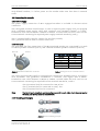
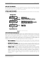
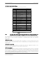
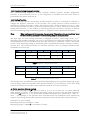
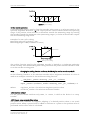
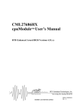
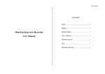
DeviceNet
Manual / Users Guide
Part No 643197-01, Doc. No 643197 Ver. 00
DeviceNet USER MANUAL
Leine & Linde AB
Content
LIST OF TABLES .................................................................................................................................. 3
LIST OF FIGURES ................................................................................................................................ 3
1 GENERAL INFORMATION ............................................................................................................... 4
1 GENERAL INFORMATION ............................................................................................................... 4
1.1 ABSOLUTE ENCODERS ...................................................................................................................... 4
1.2 DEVICENET TECHNOLOGY ................................................................................................................ 4
1.3 ABOUT LEINE & LINDE AB ............................................................................................................... 5
1.3.1 Technical and commercial support .................................................................................. 5
1.3.2 Certification of fieldbus products...................................................................................... 5
1.4 REFERENCES .................................................................................................................................... 5
1.5 ABBREVIATIONS ............................................................................................................................... 5
2 ENCODER INSTALLATION.............................................................................................................. 6
2.1 SETTINGS INSIDE THE ENCODER ........................................................................................................ 6
2.2 NODE ADDRESS/MAC ID ................................................................................................................. 6
2.3 BUS TERMINATION ........................................................................................................................... 6
2.4 BAUDRATE SETTING ......................................................................................................................... 6
2.5 CONNECTING THE ENCODER ............................................................................................................. 7
2.5.1 Power supply........................................................................................................................ 7
2.5.2 BUS lines............................................................................................................................... 7
2.5.3 Shielding philosophy........................................................................................................... 7
2.6 EDS FILE ......................................................................................................................................... 8
2.7 LED INDICATION ............................................................................................................................. 8
2.7.1 Module LED .......................................................................................................................... 8
2.8.2 Network LED ........................................................................................................................ 8
3 PROFILE OVERVIEW ........................................................................................................................ 9
4 ENCODER FUNCTIONALITY......................................................................................................... 10
4.1 BASIC ENCODER FUNCTIONALITY .................................................................................................... 10
4.2 DEVICENET FUNCTIONALITY SUPPORTED ........................................................................................ 10
4.3 DEVICENET ADOPTION OF CAN IDENTIFIERS ................................................................................... 11
4.4 ASSEMBLY INSTANCES .................................................................................................................... 11
4.5 POSITION SENSOR OBJECT (0X23HEX)................................................................................................ 12
4.5.1 Position value..................................................................................................................... 12
4.5.2 Position sensor type .......................................................................................................... 12
4.5.3 Code sequence ................................................................................................................... 12
4.5.4 Commissioning diagnostic control.................................................................................. 13
4.5.5 Scaling function................................................................................................................. 13
4.5.6 Position format .................................................................................................................. 14
4.5.7 Preset, zero-set and offset value ..................................................................................... 14
4.5.8 COS/delta............................................................................................................................ 15
4.5.9 Position limits .................................................................................................................... 15
4.5.10 Velocity ............................................................................................................................. 15
4.5.11 Operating status .............................................................................................................. 15
4.5.12 Measuring range.............................................................................................................. 15
4.5.13 Alarms .............................................................................................................................. 16
4.5.14 Warnings .......................................................................................................................... 16
4.5.15 Operating time................................................................................................................. 16
5 ENCODER COMMISSIONING EXAMPLE ....................................................................................... 17
APPENDIX A, HISTORY .................................................................................................................... 19
Part Id: 643197-01
Document Id: 643197 Ver. 00
Publication date: 2008-02-05
2
DeviceNet USER MANUAL
Leine & Linde AB
List of tables
Table 1 Pinning bus in/out- lines M12 version
.................................................................. 7
Table 2 Module LED indication............................................................................................................ 8
Table 3 Status LED indication.............................................................................................................. 8
Table 4 CAN identifier ........................................................................................................................ 11
Table 5 Assembly instances............................................................................................................... 11
Table 6 Position sensor object ........................................................................................................... 12
Table 7 Singleturn scaling attribute format .................................................................................... 13
Table 8 Total measuring range attribute format ............................................................................ 13
Table 9 Position state register ........................................................................................................... 15
Table 10 Operating status .................................................................................................................. 15
Table 11 Alarms .................................................................................................................................. 16
Table 12 Supported alarms ................................................................................................................ 16
Table 13 Warnings .............................................................................................................................. 16
Table 14 Supported warnings ............................................................................................................ 16
List of figures
Figure 1 PCB-view of a cable gland DeviceNet encoder.................................................................... 6
Figure 2 Orientation of M12 bus connectors
.................................................................. 7
Figure 3 Cable assembling principal................................................................................................... 7
Figure 4 Basic encoder functionality ................................................................................................ 10
Figure 5 Cyclic scaling ........................................................................................................................ 14
Figure 6 Non-cyclic scaling ................................................................................................................ 14
Leine & Linde AB claims copyright on this documentation. It is not allowed to modify, extend
or to hand over to a third party and/or copy this documentation without written approval
from Leine & Linde AB.
Specifications and content in this document are subject to change without prior notice due to
our continuous strives to improve functionality and performance of our products.
Part Id: 643197-01
Document Id: 643197 Ver. 00
Publication date: 2008-02-05
3
DeviceNet USER MANUAL
Leine & Linde AB
1 General information
1.1 Absolute Encoders
With an absolute encoder each angular position is assigned a coded position value generated
by a code disc equipped with several parallel fine graduations tracks which are scanned
individually. On singleturn encoders, i.e. an encoder producing absolute positions within one
revolution, the absolute position information repeats itself with every revolution. A multiturn
encoder can also distinguish between revolutions. The number of unique revolutions is
determined by the resolution of the multiturn scanning and repeats itself after the total
resolution is reached.
1.2 DeviceNet technology
DeviceNet is a low-level network that provides connections between simple industrial devices
(sensors, actuators) and higher-level devices (controllers).DeviceNet provides Master/Slave
and Peer-to-Peer capabilities over the CAN bus.
DeviceNet has two primary purposes:
-Transport of control-oriented information associated with low-level devices
-Transport of other information, which is indirectly related to the system being controlled,
such as configuration parameters.
DeviceNet makes use of abstract object modelling to describe:
-The suite of communication services available
-The externally visible behaviour of a DeviceNet node
-A common means by which information within DeviceNet products is accessed and
exchanged
A DeviceNet node is modelled as a collection of objects. An object provides an abstract
representation of a particular component within a product. The realization of this abstract
object model within a product is implementation dependent. In other words, a product
internally maps this object model in a fashion specific to its implementation.
Based on the encoder profile, see chapter 3, the following objects are implemented in the
Leine & Linde integrated encoder:
•
•
•
•
•
•
•
Identity Object. Provides identification and general information about the device. In
addition the Identity object includes the reset function.
Message Router. The Message Router Object provides a messaging connection point
through which a client may address a service to any object class or instance residing
in the physical device.
Connection Class Object. Provides the configuration and status of a poll connection
port.
DeviceNet Object. Provides the configuration and status of a DeviceNet port.
Assembly Object. Binds attributes of multiple objects, which allows data to or from
each object to be sent or received over a single connection. By addressing different
instances of the Assembly object, different collections of data are returned in each
poll cycle.
Position Sensor Object. Provides the configuration and status of the Encoder
Acknowledge Object. Used to manage the reception of message acknowledgments.
This object communicates with a message producing Application Object within a
device. The Acknowledge Handler Object notifies the producing application of
acknowledge reception, acknowledge timeouts, and production retry limit.
Part Id: 643197-01
Document Id: 643197 Ver. 00
Publication date: 2008-02-05
4
DeviceNet USER MANUAL
Leine & Linde AB
1.3 About Leine & Linde AB
For almost 40 years the Swedish based company Leine & Linde has concentrated on one thing
– development and manufacturing of advanced encoders that meet the most rigorous
demands. That is why a wide selection of incremental and absolute encoders with obvious
concentration on robust products and quality down to the last detail can be offered. Leine &
Linde encoders provide the utmost in reliability year after year, in working conditions where
vibration, dirt, cold and other harsh environments are common.
Leine & Linde can meet very specific individual customer demands. The encoders are easily
adapted, due to a modular design, to the customer’s exact need with respect to resolution,
electrical connections and interfaces, casings, etc. That is due to the fact that tomorrow’s
technology already is used today in Leine & Linde's product lines. Leine & Linde concentrate
on advanced development of intelligent encoders with integrated ASICs, new special features
and with adaptations to different fieldbus systems such as DeviceNet. This enables us to
meet the need for increasingly effective and dependable machines and automation to an even
higher degree.
1.3.1 Technical and commercial support
Leine & Linde are represented by subsidiaries in many countries around the world. In
addition, there are many services agencies and distributors located worldwide ready to reply
to commercial enquires or technical support. For more contact information, please visit our
web site or contact Leine & Linde in Strängnäs, Sweden.
Leine & Linde AB
Olivehällsvägen 8
SE-645 21 Strängnäs
Sweden
E-mail: [email protected]
web: www.leinelinde.com
Tel: +46 152 265 00
Fax: +46 152 265 05
1.3.2 Certification of fieldbus products
In order to achieve interoperability between vendors and appropriate device functionality
Leine & Linde AB continuously strives to have all fieldbus products certified by external
bodies. For questions regarding certification or conformance tests of specific products please
visit our web site or contact Leine & Linde in Strängnäs, Sweden.
1.4 References
http://www.odva.org
ODVA DeviceNet Specification 2.0
Statement of Conformance
Encoder Profile Revision 2
Encoder EDS-file
ODVA
ODVA
Leine & Linde AB
ODVA/Leine & Linde AB
Leine & Linde AB
1.5 Abbreviations
CAN
CiA
CAL
EDS
DCF
MAC
Part Id: 643197-01
Document Id: 643197 Ver. 00
Publication date: 2008-02-05
Controller Area Network
CAN in Automation
CAN Application Layer
Electronic Data Sheet
Device Configuration File
Media Access Control
5
DeviceNet USER MANUAL
Leine & Linde AB
2 Encoder Installation
2.1 Settings inside the encoder
The encoder node address and bus termination must be configured during commissioning of
the device. This is done by removing the back cover and screw off the three screws at the rear
of the encoder.
Screw terminal for bus
and power supply
connection
Node address switches
Zero-set button
Figure 1 PCB-view of a cable gland DeviceNet encoder
2.2 Node address/MAC ID
The node address or MAC ID of the device can be set using two decimal rotary switches
located inside the back cover. The weighting, x10 and x1 are specified beside the switches.
Permissible address range is between 1 and 63 but the lower addresses 0 to 2 are usually used
by the master and not recommended to be used by the device. The device address is read and
adopted when the encoder power supply is switched on, i.e. a power off and On is required in
order to adopt changes done to the address settings. The node address or MAC ID is adopted
and used to generate the CAN message identifier, see chapter 4.3
2.3 Bus termination
In a DeviceNet network, all devices are connected in a bus structure. Up to 32 devices (master
and/or slaves) can be connected in one segment. When more devices are needed repeaters
should be used to amplify the signals between segments. Generally a DeviceNet network is of
trunk-line characteristics were drop-lines are used for connecting devices on the bus. As a
consequence termination is normally done in each end of the trunk-line. Based on this bus
topology the Leine & Linde encoder doesn’t enable the possibility to set active termination.
Note:
If, for some reason, termination is required the encoder variants with M12 connectors
can make use of the standard M12 termination plugs normally supplied for DeviceNet
networks.
2.4 Baudrate setting
The Leine & Linde integrated DeviceNet encoder makes use of auto baud rate algorithm to set
the baud rate. The baud rate is detected at power on. To be able to detect the baud rate the
encoder must be commissioned on a network having at least one other node communicating
Part Id: 643197-01
Document Id: 643197 Ver. 00
Publication date: 2008-02-05
6
DeviceNet USER MANUAL
Leine & Linde AB
with defined baudrate, i.e. before power on the encoder make sure that there is network
traffic.
2.5 Connecting the encoder
2.5.1 Power supply
The power supply connection of M12 equipped encoders is included in the BUS In/Out
connection.
The cable gland encoders should always, in case of separate power supply cable, be equipped
with a shielded power supply cable with conductor area between 0,34mm2 to 1.5mm2.
Permissible outer cable diameter is ø8mm to ø10mm. Located inside the back cover are two
screw terminals containing the required power supply terminals marked (+) and (-).
The (+) terminal shall be used to connect the +EV-line (9-36Vdc).
The (-) terminal shall be used to connect the 0V-line.
2.5.2 BUS lines
The DeviceNet bus line connections of the M12 equipped encoder are constituted by a male
A-coded 5 pin M12 connector (bus in), and a female A-coded 5 pin M12 connector (bus out).
Bus out
Bus in
Bus in/out- lines M12 version
Figure 2 Orientation of M12 bus connectors
Function
Pin
CAN shield
1
+E V
2
0V
3
CAN_H
4
CAN_L
5
Table 1 Pinning bus in/out- lines M12 version
The cable gland encoders shall be equipped with twisted pair shielded cable in accordance
with DeviceNet. The guidelines recommend a conductor area higher than 0,34mm2.
Permissible outer cable diameter is ø8mm to ø10mm. Located inside the back cover are six
screw terminals containing the required bus line terminals marked H, L and G.
The (H) terminal shall be connected to CAN_H line.
The (L) terminal shall be connected to CAN_L line.
The (G) terminal shall not be connected.
Note:
The two H and L-terminals are internally connected to each other, i.e. it does not matter
to which pair the bus lines are connected to.
2.5.3 Shielding philosophy
Figure 3 Cable assembling principal
Part Id: 643197-01
Document Id: 643197 Ver. 00
Publication date: 2008-02-05
7
DeviceNet USER MANUAL
Leine & Linde AB
To achieve the highest possible noise immunity and resistance against other EMI related
disturbances the bus and power supply cables shall always be shielded. The screen should be
connected to ground on both ends of the cable. In certain cases compensation current might
flow over the screen. Therefore a potential compensation wire is recommended.
2.6 EDS file
An EDS-file is available on floppy disk (see datasheet for part number) or downloadable on
our homepage, www.leinelinde.se . Due to Leine & Linde's constant drive to support our
customer with the latest updates of encoder functionality it is recommended to consult Leine
& Linde representative for the latest releases. The EDS file describes:
• The communication functionality and objects as defined in the DeviceNet
communication profile.
• The device specific objects as defined in the Encoder Profile.
• Manufacturer specific objects.
The EDS file serves as a template for different configurations of one device type. A DCF-file is
generated from the EDS-file describing a specific configuration of the device including object
values and module-Id.
Note:
The EDS Installation procedure depends on your configuration tool; please consult your
tool supplier if problems occur.
2.7 LED indication
In order to determine the status of the encoder two LED's are visible from the rear end of the
encoder. The module LED indicates status of the encoder itself. The network status LED
shows the encoder status on the network. The LED's can be constantly on, off and flashing.
Flashing means on for 200 mS, off for 200 mS, on for 200 mS continuing.
2.7.1 Module LED
The module status LED is a bicolor LED with functionality as below.
Module LED
Off
Green
Red
Flashing Green
Flashing Red
Indication
No power.
Device operational
Unrecoverable fault
Device in standby, commissioning incomplete
Minor fault, the encoder indicates alarm
Table 2 Module LED indication
2.8.2 Network LED
The network status LED is a bicolor LED with functionality as below.
Network LED
Off
Green
Red
Flashing Green
Flashing Red
Indication
No power, Device not online
Device On-line on the network
Communication failure
Device is On-line but has no connections in the established state
One or more I/O connections are in timed-out state
Table 3 Status LED indication
When the encoder is on error free communication in on-line state both the module and the
status LED should shown green.
Part Id: 643197-01
Document Id: 643197 Ver. 00
Publication date: 2008-02-05
8
DeviceNet USER MANUAL
Leine & Linde AB
3 Profile overview
The Encoder Profile defines the functionality of encoders connected to the DeviceNet
network. In the encoder profile all Objects used from DeviceNet Object library is defined and
described. The profile describes the services available for reading position, scaling of position
value and other useful info. For further information please see the Encoder Profile
specification.
Part Id: 643197-01
Document Id: 643197 Ver. 00
Publication date: 2008-02-05
9
DeviceNet USER MANUAL
Leine & Linde AB
4 Encoder functionality
The functionality of the encoder can be divided into basic encoder functionality, describing
how the physical position is transformed to a DeviceNet position value and DeviceNet
functionality relating to functions, objects and attributes.
4.1 Basic encoder functionality
The figure below gives an overview of the basic encoder functions and how the functionality
is conduced within the encoder.
Physical position
Basic function
Absolute position
Code sequence
Singleturn resolution
Number of distinguishable revolutions
Scaling function
Measuring units per revolution
Total measuring range in measuring units
Scaling function control/status
Preset function
Preset value
Offset value
Output position value
Figure 4 Basic encoder functionality
4.2 DeviceNet functionality supported
The Leine & Linde DeviceNet encoder supports the predefined Master/Slave connection set
(group 2 only server). For retrieving position and/or velocity value basically two principals
exists, either use the Position Sensor object or to allocate a poll channel. A poll channel
returns the active assembly object instance, see chapter 4.4. The advantage to use a poll
channel instead of the position sensor object is that different poll allocation modes are
possible, i.e. also more data then position/velocity can be retrieved on a single request. For
reading position/velocity data, the following allocation modes are supported:
•
•
•
Poll I/O Connection. When the master sends a poll request, the encoder immediately
returns a poll response holding the latest calculated position value (returns the active
assembly instance).
Bit–Strobe I/O Connection. When sent by a master, all units affected (multi cast)
respond with a bitstrobe response (returns the active assembly instance). This can be
used to get a synchronised reading. Remember that the CAN-bus always priorities the
node with the lowest address to send data before a node with higher address.
Change of State. Returns a change of state response (returns the active assembly
instance), when a change of data in the assembly is detected or a max timeout have
occurred. Use the COS/delta attribute in the Position Sensor object to specify the
number of position steps that must occur before a Change of State response is
triggered. If e.g. the value 100 is used, the position value must be 100 steps larger or
smaller compared to the position value last reported to the master before a new
Change of State is triggered. Change of state can not be combined with Cyclic I/O
Connection.
Part Id: 643197-01
Document Id: 643197 Ver. 00
Publication date: 2008-02-05
10
DeviceNet USER MANUAL
•
Leine & Linde AB
Cyclic I/O Connection. Returns a Cyclic I/O response (returns the active assembly
instance), when the specified periodic time has occurred. Cyclic I/O connection can
not be combined with Change of State.
To specify which assembly instance that should be active when a poll response is returned,
use the ‘Set produced connection path’ attribute of the Connection Class object.
4.3 DeviceNet adoption of CAN identifiers
The DeviceNet communication has adopted the 11 identifier bits. They are subdivided into
four separate message groups; Group 1, Group 2, Group 3 and Group4.
Identifier Bits
10 9
8
7
0
Group 1
Message ID
6
1
0
MAC ID
1
1
1
1
1
1
Group 3
Message ID
1 1
1
1 1 1
Hex Range
Identity Usage
0x000 – 0x3FF
Message Group 1
Group 2
Message ID
Source MAC ID
0x400 – 0x5FF
Message Group 2
0x600 – 0x7BF
Message Group 3
Group 4 Message ID
1
1
X
X
X
0x7C0 – 0x7EF
0x7F0 – 0x7FF
Message Group 4
Invalid CAN ID’s
5
4
3
2
Source MAC ID
1
0
X
Table 4 CAN identifier
•
•
•
Message ID - Identifies a message within a Message Group inside a particular
end-point.
Source MAC ID - The MAC ID assigned to the transmitting node.
Destination MAC ID - The MAC ID assigned to the receiving device. Message Group 2
allows the specification of either Source or Destination within the MAC ID portion of
the CAN Identifier Field
The MAC ID uses 6 bits, which makes it possible to have 0-63 node addresses. Address 0 is not
allowed. The Leine & Linde encoder uses Message Group 2.
4.4 Assembly instances
The Leine & Linde encoder supports three assembly instances.
Byte
0
1
2
3
4
Instance 1
Position Data (Low byte)
Position Data
Position Data
Position Data (High byte)
Instance 2
Position Data (Low byte)
Position Data
Position Data
Position Data (High byte)
Bit 7-2 Bit 1
Bit 0
Unused Warning Alarm Flag
5
6
7
Velocity value
Velocity value
Velocity value (High byte)
Table 5 Assembly instances
Part Id: 643197-01
Document Id: 643197 Ver. 00
Publication date: 2008-02-05
Instance 3
Position Data (Low byte)
Position Data
Position Data
Position Data (High byte)
Velocity value (Low byte)
11
DeviceNet USER MANUAL
Leine & Linde AB
4.5 Position Sensor object (0x23hex)
The position sensor object supports the following attributes.
Attribute
3
10
11
12
13
14
15
16
17
Attribute name
Data type
Position Value (Un-scaled)
UDINT
Position Value (Scaled)
DINT
Position sensor type
UINT
Code sequence
BOOL
Commissioning diagnostic control BOOL
Scaling function control
BOOL
Position format
ENGUNITS
Measuring units per revolution
UDINT
Total measuring range in
UDINT
measuring units
18
Position measuring step
UDINT
19
Preset value
DINT
20
COS/delta
UDINT
21
Work area state register
BYTE
22
Work area low limit
DINT
23
Work area high limit
DINT
24
Velocity value
DINT
25
Velocity format
ENGUNITS
26
Velocity Resolution
UDINT
41
Operating status
BYTE
42
Physical resolution
UDINT
43
Number of distinguishable
UINT
revolutions
44
Alarms
WORD
45
Supported alarms
WORD
46
Alarm flag
BOOL
47
Warnings
WORD
48
Supported warnings
WORD
49
Warning flag
BOOL
50
Operating time
UDINT
51
Offset value
DINT
BOOL and BYTE = 1 byte, WORD,UINT and ENGUNITS = 2 byte
UDINT and DINT = 4 byte
Table 6 Position sensor object
Note:
The ‘Data Type’ Engineering Units (ENGUNITS) might not be common knowledge. For a
description of how it works, please see Appendix K-2.30 in the DeviceNet Specification.
The remaining part of this chapter describes the majority of the attributes in the position
sensor object. If more extensive explanation is required please advise the DeviceNet
specification.
4.5.1 Position value
Attribute 3 corresponds to the position data, un-scaled, i.e. the raw position data of the
encoder. Attribute 10, position data scaled, is conditioned by the scaling attributes and the
preset control.
4.5.2 Position sensor type
The position sensor type attribute can either have value 01, singleturn encoder, or 02,
multiturn encoder depending on encoder model commissioned.
4.5.3 Code sequence
The code sequence defines whether increasing or decreasing position values are outputted
when the encoder shaft rotates clockwise (CW) or counterclockwise (CCW) as seen from shaft
end. If attribute 12 is defined as “0”, clockwise (CW) the position value will increase when the
shaft is turned clockwise seen from shaft end. In contrary “1”, counter clockwise (CCW) will
give increasing values when turning the shaft counter clockwise.
Part Id: 643197-01
Document Id: 643197 Ver. 00
Publication date: 2008-02-05
12
DeviceNet USER MANUAL
Leine & Linde AB
4.5.4 Commissioning diagnostic control
The commissioning diagnostic control attribute enables internal encoder diagnostics
function. If this attribute is set to “1” the diagnostics is enabled and the actual status is
presented in the alarm attribute 44.
4.5.5 Scaling function
With the scaling function the encoder internal numerical value is converted in software to
change the physical resolution of the encoder. The scaling function control attribute 14
enables the scaling attributes to affect the position value. If this attribute is set to “1” (ON)
the scaling attributes (16 and 17) affects the outputted position value. Attribute 16 defines the
singleturn resolution, i.e. the number of measuring units per revolution. Attribute 17 defines
the total measuring range in measuring units, i.e. singleturn time’s multiturn resolution.
Note:
When scaling a multiturn encoder the parameter “Measuring units per revolution” must
be sent before the parameter “Total measuring range in measuring units”.
The data type for both scaling attributes is unsigned 32 with a value range from 1 to 232
limited by the encoder resolution. For a 25 bit encoder with a singleturn resolution of 13 bits
the permissible value for the ”Measuring units per revolution” is between 1 and 213 (8192) and
for the ”Total measuring range in measuring units” the permissible value is between 1 and 225
(33 554 432). The scaling attributes are securely stored in case of voltage breakdown and
reloaded at each start-up.
Byte
3
2
1
0
Bit
31 - 24
23 - 16
15 - 8
7 - 0
Data
231 - 224
223 - 216
215 - 28
27 - 2 0
Attribute 16 - Measuring units per revolution
Table 7 Singleturn scaling attribute format
Byte
3
2
1
0
Bit
31 - 24
23 - 16
15 - 8
7 - 0
Data
231 - 224
223 - 216
215 - 28
27 - 2 0
Attribute 17 - Total measuring range in measuring units
Table 8 Total measuring range attribute format
The encoder has two different operating modes depending on the specified measuring range.
If the scaling is binary the encoder enter operation mode A, cyclic operation, and if the scaling
value is non-binary the encoder enters operation mode B, non cyclic operation.
A. Cyclic operation (Binary scaling)
Used when operating with 2X number of turns (2, 4, 8, 16, 32, 64, 128, 256, 512, 1024, 2048 and
4096 number of turns). If the desired measuring range is equal to the specified singleturn
resolution * 2X (where x <= 12) the encoder operates in endless cyclic operation (0 - max - 0 max ...). For example: If the position value increases above the maximum value (measuring
range-1) by rotating the encoder beyond the maximum value the encoder continues from 0.
Example of a cyclic scaling:
Measuring units per revolution = 1000
Measuring range = 32000 (25 = 32 number of turns)
Part Id: 643197-01
Document Id: 643197 Ver. 00
Publication date: 2008-02-05
13
DeviceNet USER MANUAL
Leine & Linde AB
Figure 5 Cyclic scaling
B. Non cyclic operation
If the measuring range is used to limit the encoder value range to a value not equal to the
specified singleturn resolution * 2x the output position value is limited within the operating
range. If the position value increases or decreases outside the measuring range by rotating
the encoder beyond the maximum value (measuring range-1) or below 0 the encoder outputs
the total measuring range value.
Example of a non-cyclic scaling:
Measuring units per revolution = 100
Measuring range = 5000 (50 number of turns)
Figure 6 Non-cyclic scaling
The scaling function used in the DeviceNet encoder is limited to a singleturn resolution
within one step. After downloading new scaling attributes the preset function should be used
to set the encoder starting point.
Note:
Changing the scaling function attributes should only be used at encoder standstill.
In the following formula a 25 bit multiturn encoder with a singleturn resolution of 13 bits is
used as an example. Formula for the multiturn scaling function:
(sin gleturn _ position × measuring _ units _ per _ revolution )
8192
output _ position = (revolution _ number × measuring _ units _ per _ revolution) + A
A=
Where:
singleturn_position = the Absolute singleturn position value
revolution_number = the Absolute multiturn number
4.5.6 Position format
For the position format attribute only 1001h, i.e. counts, is valid as the device is a rotary
encoder.
4.5.7 Preset, zero-set and offset value
The preset value, attribute 19, supports adapting of a desired position value to an actual
position value. When a preset value is added to attribute 19 a preset to the position value is
performed and an offset value is calculated.
Part Id: 643197-01
Document Id: 643197 Ver. 00
Publication date: 2008-02-05
14
DeviceNet USER MANUAL
Leine & Linde AB
offset _ value = preset _ value − current _ value
Setup calculation:
The offset value is continuously added to the internal encoder position value resulting in a
position value continuously affected by the preset value.
output _ position = curren _ position + offset _ value
Runtime calculation:
The calculated offset value will remain constant (until the preset value is changed) and can
be accessed in attribute 51 and is securely stored in case of voltage breakdown and reloaded
at each start-up.
Note:
The preset function should only be used at encoder standstill. Depending on encoder
type the number of possible preset cycles is limited; please consult Leine & Linde for
more information.
Zero setting of the encoder can be done two folded. Using the preset attribute and set the
preset value to zero makes a zero-set of the encoder. Also, if the zero set button, inside the
back cover of the encoder, is pushed for at least 1 second the position value will be set to zero.
4.5.8 COS/delta
The COS/delta attribute defines the number of position values that must be passed before a
change of state response is generated. If this value is set to 0 a COS response will be generated
at every change in position value.
4.5.9 Position limits
Using the attributes 22-23 a work area can be defined, i.e. high and low limit value. In
attribute 21 the status of the work area is presented. Whenever the actual position value is
out of range bit 0 of the state register is set. Bit 1 and 2 indicates weather an under or over
flow is detected.
Bit 7
Reserved
Bit6
Reserved
Bit5
Reserved
Bit4
Reserved
Bit3
Reserved
Bit2
Range
underflow
Bit1
Range
overflow
Bit0
Out of
range
Table 9 Position state register
4.5.10 Velocity
Attribute 24 presents the velocity value of the encoder shaft. The resolution and unit of the
represented velocity value is stated by attribute 25 and 26. Attribute 25, velocity format, is a
read/write attribute defining the unit of the outputted velocity value. The attribute value
1F04hex, count/sec, is default but also DF0Fhex, RPM, and DF0Ehex, RPS, is accepted.
4.5.11 Operating status
This attribute basically contains status of the code sequence and scaling functionality. No
vendor specific status bits are implemented.
Bit
0
1
2..4
5..7
Description
Code sequence
Scaling
Reserved by DeviceNet
Vendor specific
FLASE (0)
Increasing
Off
TRUE (1)
Decreasing
On
Table 10 Operating status
4.5.12 Measuring range
Attribute 42, singleturn resolution, and attribute 43, multiturn resolution, defines the physical
resolution of the encoder, i.e. the basic resolution of the encoder when scaling function is
disabled.
Part Id: 643197-01
Document Id: 643197 Ver. 00
Publication date: 2008-02-05
15
DeviceNet USER MANUAL
Leine & Linde AB
4.5.13 Alarms
The encoder supports position error alarm according to the definition below.
Bit
0
1
2..11
12..15
Description
Position error
Diagnostic error
Reserved by DeviceNet
Vendor specific
FLASE (0)
NO
NO
TRUE (1)
YES
YES
Table 11 Alarms
Bit
0
1
2..11
12..15
Description
Position error
Diagnostic error
Reserved by DeviceNet
Vendor specific
FLASE (0)
Not supported
Not supported
TRUE (1)
Supported
Supported
Table 12 Supported alarms
4.5.14 Warnings
The encoder supports warnings according to the definition below.
Bit
0
1
2
3..10
11..12
13..15
Description
Frequency exceeded
Light control reserve
CPU watchdog
For specific definition, see
encoder profile
Reserved by CIP
Vendor specific
FLASE (0)
NO
Not reached
OK
TRUE (1)
YES
Error
Reset generated
Always 0
Table 13 Warnings
Bit
0
1
2
3..10
11..12
13..15
Description
Frequency exceeded
Light control reserve
CPU watchdog
For specific definition, see
encoder profile
Reserved by CIP
Vendor specific
FLASE (0)
Not supported
Not supported
Not supported
Not supported
TRUE (1)
Supported
Supported
Supported
Supported
Always 0
Table 14 Supported warnings
Note:
Bit 1, light control reserve, is supported depending on encoder model; please
consult Leine & Linde for more information.
4.5.15 Operating time
The operating time attribute is read only and is incremented as long as the encoder is
powered on. The operating time is present as tenths (0.1) of an hour, i.e. attribute value 10is
equal to 1 hour operating time.
Part Id: 643197-01
Document Id: 643197 Ver. 00
Publication date: 2008-02-05
16
DeviceNet USER MANUAL
Leine & Linde AB
5 Encoder commissioning example
This example shows a simple setup of the encoder for cyclic transmission of the position
value.
Note:
Since commissioning is software tool dependent, the steps below must be adapted to the
specific tool in use. Also the example only shows how the scanner part is made.
1
Set the physical address (Node Number) of the encoder using the address switches.
2
Power up the encoder.
3
In RSNetworx, click on the “go on-line” button to connect to the DeviceNet network.
4
The encoder will send a Boot-up message (Duplicate MAC message) when the
baudrate is detected. If no other node responds on the MAC request the encoder is
online and waiting for a master to connect. In case another node is responding the
encoder enters offline and indicates accordingly on the LED’s.
5
Scan the network. When all expected units on the network have appeared, doubleclick the scanner icon to bring up its property view.
6
Select the Scanlist tab. All units added to the Scanlist will be polled by the
scanner/PLC.
Part Id: 643197-01
Document Id: 643197 Ver. 00
Publication date: 2008-02-05
17
DeviceNet USER MANUAL
Leine & Linde AB
7
Click the “>” button to add the encoder to the Scanlist.
8
Select the Input tab.
9
Confirm the mapping of the encoder value in the PLC image file. Click OK to close the
property page and download the changes to the scanner device.
10 Now the scanner will gather all position data from all units in its scanlist and put in
the image file.
Part Id: 643197-01
Document Id: 643197 Ver. 00
Publication date: 2008-02-05
18
DeviceNet USER MANUAL
Leine & Linde AB
Appendix A, History
Revision
Date
Changes
Rev. 1.0
07-07-01
First release
Rev. 1.1
07-10-30
Extended information regarding scaling parameters
Excluded information regarding LLS service
Part Id: 643197-01
Document Id: 643197 Ver. 00
Publication date: 2008-02-05
19