1
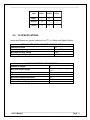
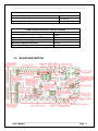
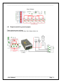
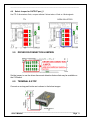
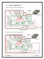
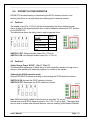
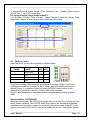
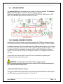
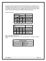
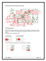
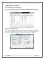
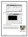
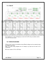
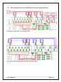
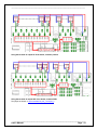
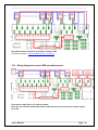
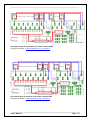
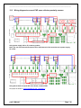
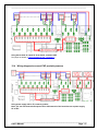
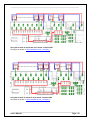
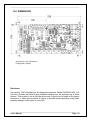
USER’S MANUAL C62- DUAL PORT MULTIFUNCTION CNC BOARD Rev. 3.1 DECEMBER, 2014 ___________________________________________________________________________ User’s Manual Page i USER'S MANUAL TABLE OF CONTENTS Page # Contents 1.0 FEATURES ..................................................................................................................... 1 2.0 SPECIFICATIONS .......................................................................................................... 2 3.0 BOARD DESCRIPTION .................................................................................................. 3 4.0 POWER TERMINALS AND CONFIGURATION JUMPERS ............................................ 4 4.1 Power terminal ............................................................................................................. 4 4.2 Output 5V External ....................................................................................................... 4 4.3 Output 24V External .................................................................................................... 4 4.4 Input terminals for port_1 and port_2 ........................................................................ 4 4.5 Select JUMPER COM for the inputs of port_1 and port_2 ......................................... 5 4.6 Controller selection jumpers (IEEE1284/SS) .............................................................. 7 4.7 TTL or open collector outputs can be used for driver connection. .......................... 7 4.8 Output terminal for general purpose .......................................................................... 8 4.9 Select Jumper for OUTPUT port_2 .............................................................................. 9 5.0 Driver Disconnection Jumpers ..................................................................................... 9 6.0 TERMINAL E-STOP........................................................................................................ 9 7.0 TYPICAL CONNECTIONS ............................................................................................ 10 8.0 DIPSWITCH CONFIGURATION ................................................................................... 11 8.1 Position 1 .................................................................................................................... 11 8.2 Position 2 .................................................................................................................... 11 8.3 Position 3 and 4 .......................................................................................................... 12 9.0 LED INDICATOR .......................................................................................................... 14 10.0 VARIABLE SPEED CONTROL..................................................................................... 14 11.0 PINOUT......................................................................................................................... 21 12.0 WIRING DIAGRAMS..................................................................................................... 21 12.1 Wiring diagram to connect NPN open collector proximity sensors. .................... 22 12.2 Wiring diagram to connect NPN proximity sensors............................................... 24 12.3 Wiring diagram to connect PNP open collector proximity sensors ...................... 26 12.4 Wiring diagram to connect PNP proximity sensors ............................................... 27 13.0 DIMENSIONS................................................................................................................ 29 ___________________________________________________________________________ User’s Manual Page ii ____________________________________________________________________________ 1.0 FEATURES Connects directly to the motion controller or Parallel Ports. IEEE 1284 Standard compatible. Built-in PWM-Based Speed Control. Two Built-in Electromechanical Relays with NO and NC positions for spindle control. RJ45 Connector for Easy VFD Connection. Monitors E-Stop, Safety Charge Pump and fault signal from drivers. Monitors VFD alarm signal. Can enable and disable the drives. Electromechanical Relay with NO and NC positions for general purpose (Port_2 16 or 17, jumper-selectable). Microcontroller based SCHP. RJ45 connectors for the axis. Optoisolated inputs. Power terminal (24VDC). Outputs can be 500mA open collector or +5vdc at 24mA TTL. Status LEDs on all inputs and output connections. Works directly with popular CNC hardware and software. 18 inputs and 16 outputs on 2 ports. ___________________________________________________________________________ User’s Manual Page 1 ____________________________________________________________________________ 2.0 PINS PORT1 PORT2 INPUT 5 13 OUTPUT 12 4 TOTAL 17 17 TOTAL 18 16 34 I/O SPECIFICATIONS. Inputs and Outputs are jumper selected to be TTL or +24vdc and Open Collector. OPTOISOLATED DIGITAL INPUT TTL SPECIFICATIONS Numbers of inputs On-state voltage range Maximum off-state voltage 18 2 to 5V DC 0.8V Typical signal delay 2.8uS DIGITAL OUTPUT TTL SPECIFICATIONS Number of outputs 16 (5V power supply voltage) + Maximum output voltage 0.5V Typical output current 24mA Maximum off-state voltage 0.44 V Maximum supported frequency 4M Typical signal delay 10 nS Time of transition to high impedance state 120mS* ___________________________________________________________________________ User’s Manual Page 2 ____________________________________________________________________________ OPTOISOLATED DIGITAL INPUT SPECIFICATIONS Numbers of inputs On-state voltage range 18 5 to 24V DC Typical signal delay Less than 500uS OPEN COLLECTOR OUTPUT SPECIFICATIONS Number of outputs 16 Maximum Supported output voltage 30VDC Typical output current (DIR and STEP outputs) 30mA Typical output current (general purpose pins) 500mA Maximum supported frequency 250KHz Typical signal delay Less than 8nS 3.0 BOARD DESCRIPTION ___________________________________________________________________________ User’s Manual Page 3 ____________________________________________________________________________ 4.0 4.1 POWER TERMINALS AND CONFIGURATION JUMPERS Power terminal This input requires an external power 24VDC@700mA if not using the board to supply power to external devices. 4.2 Output 5V External 5V@200mA can be sourced to sensors or other cards requiring it. 4.3 Output 24V External 24V@300mA can be sourced to sensors or other cards requiring it. 4.4 Input terminals for port_1 and port_2 These terminals supports signals 5VDC or 24VDC, you can connect sensors NPN, PNP, switches, capacitive sensors, etc. set jumpers depending on signal voltage (5VDC or 24VDC). For see connection diagram go to WIRING DIAGRAMS ___________________________________________________________________________ User’s Manual Page 4 ____________________________________________________________________________ PORT_1 INPUT 5V INPUT 24V Jumper position changed PORT_2 INPUT 5V INPUT 24V Jumper position changed 4.5 Select JUMPER COM for the inputs of port_1 and port_2 Set the Jumper tp COM = +5VDC, GND or 24VDC to determine the common for the input signals to be used. ___________________________________________________________________________ User’s Manual Page 5 ____________________________________________________________________________ COM = 5V PORT_2 PORT_1 COM = GND with 5V COM = GND with 24V Jumper position changed ___________________________________________________________________________ User’s Manual Page 6 ____________________________________________________________________________ COM = 24V 4.6 Controller selection jumpers (IEEE1284/SS) Some motion controllers are not IEEE1284 compatible, set the jumper select the compatibility. Set it Non-Compatible if pull-up resistors in the motion controllers activate outputs when not supposed to. Compatible (IEEE1284) 4.7 Not Compatible (IEEE1284) TTL or open collector outputs can be used for driver connection. Use TTL if driver takes +5vdc, or open collector if driver takes +12vdc or +24vdc signals. TTL ___________________________________________________________________________ User’s Manual Page 7 ____________________________________________________________________________ Open Collector Jumper position changed 4.8 Output terminal for general purpose These outputs are open collector In this terminal can be connected relay, led or lamps, alarm, etc. ___________________________________________________________________________ User’s Manual Page 8 ____________________________________________________________________________ 4.9 Select Jumper for OUTPUT port_2 Use TTL if driver takes +5vdc, or open collector if driver takes +12vdc or +24vdc signals. TTL OPEN COLLECTOR Jumper position changed 5.0 DRIVER DISCONNECTION JUMPERS Set the jumper to use the driver disconnect detection feature that may be available on the C34 board. 6.0 TERMINAL E-STOP Connect an e-stop push button as is shown in the below images. ___________________________________________________________________________ User’s Manual Page 9 ____________________________________________________________________________ 7.0 TYPICAL CONNECTIONS -Connection with the terminal of output external of 24V -Connection with the terminal of output external of 5V ___________________________________________________________________________ User’s Manual Page 10 ____________________________________________________________________________ 8.0 DIPSWITCH CONFIGURATION DIPSWITCH allows activating or deactivating the SCHP detection function, and selecting the driver to use and delays an enable signal for external devices. 8.1 Position 1 The enable output (Pin 17-Port 2) will be activated when the driver enable process starts. A delay in the signal activation time could be added by selecting the OFF position in the DIPSWITCH. The table below shows the delay time for each supported driver. DRIVER G320/340 G203 G210/201/Keling Viper Servo driver DELAY (Sec.) 5 2 2 5 SWITCH 1 OFF: Delayed enable output (Pin 17-Port 2). SWITCH 1 ON: Non Delayed enable output (Pin 17-Port 2). 8.2 Position 2 Safety Charge Pump “SCHP”. (Pin 17 “Port 2”) This board takes advantage of Mach ability to send a specific frequency through one of the pins of the parallel port when the program is in control of the system. Selecting the SCHP operation mode Onboard DIPSWITCH allows activating or deactivating the SCHP detection function. SWITCH 2 ON: Activate the SCHP detection function. SWITCH 2 OFF: Deactivate the SCHP detection function. Note: When the Safety Charge Pump function is activated, 5V are present in the E-Stop terminal and a valid SCHP signal is present, Port 2 Pin 17 will go high. This high signal can be used to enable other external devices, such as enabling other Breakout Boards, ___________________________________________________________________________ User’s Manual Page 11 ____________________________________________________________________________ or relays that would enable servos, VFDs, contactors, etc….Variable Speed Control (pin 14 “Port 1” ) and VFD connection. For Configuring the Charge Pump in Mach X: Use the dialog Config / Ports and pins / Output Signals. Enable the Charge Pump output and configure it as is shown to Next, press the apply button. 8.3 Position 3 and 4 Select the driver you will use according to the table below. OPERATION MODE Mode 1 COMPATIBLE DRIVER DIP 3 DIP 4 G320/DG4S 0 0 Mode 2 G203 1 0 Mode 3 G210/201/Keling 0 1 Viper 1 1 Mode 4 This board includes a Microcontroller-based driver monitoring system. It performs enabling and monitoring functions for servo Drivers, and only enabling function for stepper drivers. It is required connect the driver ERR/RES (servo drivers) or EN (stepper driver) terminal to the pin 5 of each RJ45 driver connector. Here is a brief description of how these functions are performed for each operation mode. Operation Mode 1 (G320/DG4S) When the system starts, the C62 error/reset pins go to a low state (0V), making sure the driver remains disabled. When SCHP and E-Stop function are checked and validated and there is no fault signal coming from any driver, the system sends a high (5V) to the driver’s error/reset pins for about 5 seconds to enable the drivers. After that the system ___________________________________________________________________________ User’s Manual Page 12 ____________________________________________________________________________ monitors the driver’s err/res pins. If a fault occurs on any driver (0V in driver ERR/RES pin) or an external fault occurs (E-Stop or SCHP fault), the system stops and sends an e-stop signal (Active low) to the controller. All outputs on the board are disabled and the drivers will be disabled by sending a LOW (0V) to the drivers ERR/RES pin. The system will remain that way until the conditions to restart are present again. Operation Mode 2 (G203) When the system starts, the C62 enable pins go to a HIGH state (5V). When SCHP and E-Stop function are checked and validated, the system send a LOW (0V) to the driver’s EN pin for about 2 Sec, enabling the drivers. If an external error occurs, the system stops, resets the CNC software and sends a HIGH (5V) to the drivers EN pin. The system will remain that way until the conditions to restart are present again. Operation Mode 3 (G210/201) When the system starts, the C62 enable pins go to a LOW state (0V). When SCHP and E-Stop function are checked and validated, the system send a HIGH (5V) to the Drivers EN pin for about 2 Sec, enabling the Drivers. If an external error occurs, the system stops, resets the CNC software and sends a LOW (0V) to the drivers EN pin. The system will remain that way until the conditions to restart are present again. Operation Mode 4 (Viper, Teco and Delta) When the system starts, the C62 enable pins go to a low state (0V). When SCHP and E-Stop function are checked and validated and there is no fault signal coming from any driver, the system sends a high (5V) to the driver Fault output pin, enabling the drivers. After that the system monitors the driver’s Fault Output pin. If an error is generated in any driver (0V in driver Fault Output pin) or an external error occurs, the system stops, resets the CNC software and sends a LOW (0V) to the drivers to ensure they remain disabled. ___________________________________________________________________________ User’s Manual Page 13 ____________________________________________________________________________ 9.0 LED INDICATOR The standby LED lights indicates that the system is ready but disabled. When Status LED, (Green LED) lights, it indicates that the system is enabled. There are 4 possible error sources: a driver fault, E-STOP error, SCHP error or VFD alarm. An LED will light close to the source of the fault. 10.0 VARIABLE SPEED CONTROL Variable Speed Control allows controlling the spindle with PWM and direction signals, as if it was an axis motor. It converts the PWM signal into an analog (0-10VDC) signal. A Variable Frequency Drive or Inverter works by modifying the frequency for AC motors. You can control most of these devices with an external analog signal (0-10VDC). That is, if there is 5VDC control signal, the motor will run at 50% of full speed, if there is 10VDC, the motor will run at 100% of full speed. If there is no voltage, then the motor will stop. This function can also be used on many DC motor controllers by replacing the potentiometer that controls the speed. WARNING: You will require a voltmeter to fine tune your system. Before connecting anything, please be sure to read your VFD’s manual and make sure you understand all the safety issues. - Operation Mode Selection Jumper This jumper allows selecting the way how the relays are activated when a PWM signal and REV signal are present in the pins 1_14 and 1_16. ___________________________________________________________________________ User’s Manual Page 14 ____________________________________________________________________________ In US mode one relay is used to start on CW and the other one to start on CCW. In international mode one relay is used for on/off, and the other one to indicate the CW or CCW rotation of the spindle motor. This board uses the step and direction setting for the spindle motor under motor output in Mach3 to generate the required action on the relays. For both cases the presence of PWM will indicate spindle start. See the tables below. US MODE (INT) PIN 1_14 PWM PWM 0 0 RELAYS 1_16 1 0 1 0 REL 1 OFF ON OFF OFF REL 2 ON OFF OFF OFF OPERATION Spindle ON CCW Spindle ON CW Spindle Off Spindle Off INTERNATIONAL MODE (INT) INPUTS 1_14 PWM PWM 0 0 1_16 1 0 1 0 RELAYS REL 1 ON ON OFF OFF REL 2 ON OFF OFF OFF OPERATION Spindle ON CCW Spindle ON CW Spindle Off Spindle Off Relay 1 and 2 (Pins 16 “Port 1”) They can be used to control the VFD. The relay specifications are shown in the table below. ELECTROMECHANICAL RELAYS SPECIFICATIONS 7A@240VAC; Maximum Current (AC) 10A@125VAC 15A@24VDC; Maximum Current (DC) 10A@28VDC ___________________________________________________________________________ User’s Manual Page 15 ____________________________________________________________________________ RJ45 for VFD Connection This RJ45 port let you make an easy connection between this board and the VFD. RJ45 for VFD RJ45 PIN Function 1 Analog GND 2 Analog Output 3 VFD Alarm 4 REL 1 Normally Open Contact 5 GND VFD 6 REL 2 Normally Open Contact 7 Ext. 12VDC or 24VDC 8 Relay Common An. GND: Ground of the Analog output signal Analog Output: Isolated Analog Output Signal (0-10V) VFD Alarm: Alarm signal generated by the VFD. (See VFD ALARM JUMPERS section) GND VFD: Ground of VFD when it is powered with external source of 24V Ext. 12VDC or 24VDC: External 12VDC or 24VDC power supply used to enable the VFD. Relay Common: The signal or voltage wired to this terminal can be connected to the common terminals of the relay 1 and relay 2. Use the on-board RELAY COMMON JUMPERS to do this connection. Remove the jumper if this connection is not required. ___________________________________________________________________________ User’s Manual Page 16 ____________________________________________________________________________ VFD Connection and configuration jumpers VFD Alarm jumpers Many VFDs have general purpose relay that can be configured to generate an alarm (Use its N.C. contacts). This board takes advantage of this feature to monitor the VFD status. Set jumper as shown below for VFD 1and 2: pull up 2 and 3:pull down The VFD Alarm monitoring feature can be enabled or disabled: ___________________________________________________________________________ User’s Manual Page 17 ____________________________________________________________________________ Configuring the Control Software: For configuring Mach X follow these steps: Go to Config / Ports&Pins / Motor Outputs. Enable the spindle and select the port and pins you wired for step and direction. Ports&Pins configuration screenshot Go to Config / Ports&Pins / Spindle Setup. In the motor control box, check Use Spindle Motor Output and PWM Control with a frequency of 300Hz. If using an external motion controller, like the Smooth Stepper, this needs to be configured in the plugin too. ___________________________________________________________________________ User’s Manual Page 18 ____________________________________________________________________________ Under Pulley Ratios set the pulley ratios of the machine. Spindle Setup screenshot Go to Config / Motor Tuning / Spindle. Set the velocity and acceleration to the max. Motor Tuning and Setup screenshot After configuring the Mach, these steps should be followed. Connect a multimeter to the analog output terminals to fine tune the analog output. Comment the spindle to go at max speed and make sure you get +10vdc. To adjust it you can play with the potentiometer or the max speed you have set under motor tuning. ___________________________________________________________________________ User’s Manual Page 19 ____________________________________________________________________________ Replacing a Potentiometer: This circuit can be used to replace a potentiometer of a DC motor speed control circuits. This speed controller circuits are very commonly used by SIEG, KB Electronics, and many other Asian machines. Before explaining how to do it, please first keep in mind that it can be done if the voltage that goes though the pot is +12vdc or less. This circuit cannot be used for AC currents. In most cases the terminals that go to the potentiometer will carry these signals: P1 = GND P2 = WIPER P3 = REFERENCE VOLTAGE These are the steps for replacing a potentiometer: Measure the voltage difference between P1 and P3. Make sure it measures under +12vdc. Fine tune the analog output to the output voltage you got from step 1. Connect the ground from the analog output to the ground of the potentiometer (P1). Connect the analog output to the wiper connection of the potentiometer (P2). ___________________________________________________________________________ User’s Manual Page 20 ____________________________________________________________________________ 11.0 PINOUT RJ45 Distribution P_P: Parallel port or Smooth Stepper pin, where the first P is the port number and the second P is the pin number. 12.0 WIRING DIAGRAMS Different kind of sensors and switches using different voltages can be connected using the diagrams that follow: Note: The below wiring diagrams are an example, any input can be used for the connections. R1= use a resistor of 100 to 200 Ohms ___________________________________________________________________________ User’s Manual Page 21 ____________________________________________________________________________ 12.1 Wiring diagram to connect NPN open collector proximity sensors. Using power supply 24V or 5V, common positive Using the terminal of output 24V of the board, common positive ___________________________________________________________________________ User’s Manual Page 22 ____________________________________________________________________________ Using the terminal of output 5V of the board, common positive Using the terminal of output 24V of the board, common GND. Set jumper as shown in Input terminals for port_1 and port_2 ___________________________________________________________________________ User’s Manual Page 23 ____________________________________________________________________________ Using the terminal of output 5V of the board, common GND. Set jumper as shown in Input terminals for port_1 and port_2 12.2 Wiring diagram to connect NPN proximity sensors Using power supply 24V or 5V, common positive Note: you can use the terminal output of 5V or 24V external of the board lest use a power supply 5V or 24V. ___________________________________________________________________________ User’s Manual Page 24 ____________________________________________________________________________ Using the terminal of output 24V of the board, common GND. Set jumper as shown in Input terminals for port_1 and port_2 Using the terminal of output 5V of the board, common GND. Set jumper as shown in Input terminals for port_1 and port_2 ___________________________________________________________________________ User’s Manual Page 25 ____________________________________________________________________________ 12.3 Wiring diagram to connect PNP open collector proximity sensors Using power supply 24V or 5V, common positive Note: you can use the terminal output of 5V or 24V external of the board lest use a power supply 5V or 24V. Using the terminal of output 24V of the board, common GND. Set jumper as shown in Input terminals for port_1 and port_2 ___________________________________________________________________________ User’s Manual Page 26 ____________________________________________________________________________ Using the terminal of output 5V of the board, common GND. Set jumper as shown in Input terminals for port_1 and port_2 12.4 Wiring diagram to connect PNP proximity sensors Using power supply 24V or 5V, common positive Note: you can use the terminal output of 5V or 24V external of the board lest use a power supply 5V or 24V. ___________________________________________________________________________ User’s Manual Page 27 ____________________________________________________________________________ Using the terminal of output 24V of the board, common GND. Set jumper as shown in Input terminals for port_1 and port_2 Using the terminal of output 5V of the board, common GND. Set jumper as shown in Input terminals for port_1 and port_2 ___________________________________________________________________________ User’s Manual Page 28 ____________________________________________________________________________ 13.0 DIMENSIONS All dimensions are in Millimeters. Fixing holes (3.8mm) Disclaimer: Use caution. CNC machines can be dangerous machines. Neither DUNCAN USA, LLC nor Arturo Duncan are liable for any accidents resulting from the improper use of these devices. This product is not a fail-safe device and it should not be used in life support systems or in other devices where its failure or possible erratic operation could cause property damage, bodily injury or loss of life. ___________________________________________________________________________ User’s Manual Page 29