1
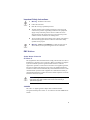
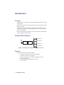
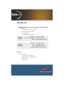
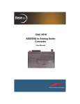
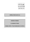
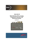
SRA-9601
3G/HD/SD Reclocking
Distribution Amplifier
User Manual
Thank you for choosing Ross
You've made a great choice. We expect you will be very happy with your
purchase of Ross Technology.
Our mission is to:
1.
Provide a Superior Customer Experience
• offer the best product quality and support
2.
Make Cool Practical Technology
• develop great products that customers love
Ross has become well known for the Ross Video Code of Ethics. It
guides our interactions and empowers our employees. I hope you enjoy
reading it below.
If anything at all with your Ross experience does not live up to your
expectations be sure to reach out to us at [email protected].
David Ross
CEO, Ross Video
[email protected]
Ross Video Code of Ethics
Any company is the sum total of the people that make things happen. At
Ross, our employees are a special group. Our employees truly care
about doing a great job and delivering a high quality customer
experience every day. This code of ethics hangs on the wall of all Ross
Video locations to guide our behavior:
1
1.
We will always act in our customers’ best interest.
2.
We will do our best to understand our customers’ requirements.
3.
We will not ship crap.
4.
We will be great to work with.
5.
We will do something extra for our customers, as an apology, when
something big goes wrong and it's our fault.
6.
We will keep our promises.
7.
We will treat the competition with respect.
8.
We will cooperate with and help other friendly companies.
9.
We will go above and beyond in times of crisis. If there's no one to
authorize the required action in times of company or customer crisis
- do what you know in your heart is right. (You may rent helicopters if
necessary.)
SRA-9601 User Manual
•
Ross Part Number: 9601DR-004-02
•
Release Date: September 23, 2013.
The information contained in this manual is subject to change without notice or
obligation.
Copyright
© 2013 Ross Video Limited. All rights reserved.
This work is proprietary and confidential to Ross Video Limited, its subsidiaries
and its other affiliated corporations and may not be copied, distributed, sold or
otherwise used or relied upon without the express written permission of Ross
Video Limited. Reproduction or reverse engineering of copyrighted software is
prohibited.
Patents
This product is protected by the following US Patents: 4,205,346; 5,115,314;
5,280,346; 5,561,404; 7,034,886; 7,508,455; 7,602,446; 7,834,886; 7,914,332.
This product is protected by the following Canadian Patents: 2039277;
1237518; 1127289. Other patents pending.
Notice
The material in this manual is furnished for informational use only. It is subject
to change without notice and should not be construed as commitment by Ross
Video Limited. Ross Video Limited assumes no responsibility or liability for
errors or inaccuracies that may appear in this manual.
Trademarks
•
•
is a registered trademark of Ross Video Limited.
is a trademark of Ross Video Limited.
•
Ross, ROSS, ROSS®, and MLE are registered trademarks of Ross
Video Limited.
•
VELCRO® is a registered trademark of Velcro Industries B.V.
•
All other product names and any registered and unregistered
trademarks mentioned in this manual are used for identification
purposes only and remain the exclusive property of their respective
owners.
2
Important Regulatory and Safety Notices to Service
Personnel
Before using this product and any associated equipment, refer to the
“Important Safety Instructions” listed below to avoid personnel injury and to
prevent product damage.
Product may require specific equipment, and/or installation procedures to be
carried out to satisfy certain regulatory compliance requirements. Notices have
been included in this publication to call attention to these specific requirements.
Symbol Meanings
Protective Earth — This symbol identifies a Protective Earth (PE)
terminal, which is provided for connection of the supply system’s
protective earth (green or green/yellow) conductor.
This symbol on the equipment refers you to important operating and
maintenance (servicing) instructions within the Product Manual
Documentation. Failure to heed this information may present a major
risk of damage or injury to persons or equipment.
Warning — The symbol with the word “Warning” within the
equipment manual indicates a potentially hazardous situation which, if
not avoided, could result in death or serious injury.
Caution — The symbol with the word “Caution” within the
equipment manual indicates a potentially hazardous situation which, if
not avoided, may result in minor or moderate injury. It may also be
used to alert against unsafe practices.
Warning Hazardous Voltages — This symbol is intended to alert
the user to the presence of uninsulated “dangerous voltage” within the
product enclosure that may be of sufficient magnitude to constitute a
risk of shock to persons.
ESD Susceptibility — This symbol is used to alert the user that an
electrical or electronic device or assembly is susceptible to damage
from an ESD event.
3
Important Safety Instructions
1.
Warning – Read these instructions.
2.
Follow all instructions.
3.
Refer all servicing to qualified personnel.
4.
The safe operation of this product requires that a protective earth
connection be provided. A grounding conductor in the equipment's
supply cord provides this protective earth. To reduce the risk of
electrical shock to the operator and service personnel, this ground
conductor must be connected to an earthed ground.
5.
The AC appliance inlet on the product’s power supply is the means to
disconnect the supply from the AC Mains. It must remain readily
operable for this purpose.
6.
Warning – Indoor Use: WARNING: To reduce the risk of fire or
electric shock, do not expose this apparatus to rain or moisture.
EMC Notices
United States of America
FCC Part 15
This equipment has been tested and found to comply with the limits for a class A
Digital device, pursuant to part 15 of the FCC Rules. These limits are designed
to provide reasonable protection against harmful interference when the
equipment is operated in a commercial environment. This equipment generates,
uses, and can radiate radio frequency energy and, if not installed and used in
accordance with the instruction manual, may cause harmful interference to radio
communications. Operation of this equipment in a residential area is likely to
cause harmful interference in which case the user will be required to correct the
interference at his own expense.
Notice — Changes or modifications to this equipment not expressly
approved by Ross Video Limited could void the user’s authority to
operate this equipment.
CANADA
This Class “A” digital apparatus complies with Canadian ICES-003.
Cet appariel numerique de la classe “A” est conforme a la norme NMB-003 du
Canada.
4
EUROPE
This equipment is in compliance with the essential requirements and other
relevant provisions of CE Directive 93/68/EEC.
INTERNATIONAL
This equipment has been tested to CISPR 22:2009 and found to comply with
the limits for a Class A Digital device.
AUSTRALIA
This equipment has been tested to AS/NZS CISPR 22:2009, and found to
comply with the limits for a Class A Digital device.
Maintenance/User Serviceable Parts
Routine maintenance to this GearLite product is not required. This product
contains no user serviceable parts. If the module does not appear to be working
properly, please contact Technical Support using the numbers listed under the
“Contact Us” section on the last page of this manual. All GearLite products are
covered by a generous 3-year warranty and will be repaired without charge for
materials or labor within this period. See the “Warranty and Repair Policy”
section in this manual for details.
Environmental Information
The equipment that you purchased required the extraction and use
of natural resources for its production. It may contain hazardous
substances that could impact health and the environment.
To avoid the potential release of those substances into the environment and to
diminish the need for the extraction of natural resources, Ross Video encourages
you to use the appropriate take-back systems. These systems will reuse or
recycle most of the materials from your end-of-life equipment in an
environmentally friendly and health conscious manner.
The crossed-out wheeled bin symbol invites you to use these systems.
5
If you need more information on the collection, reuse, and recycling systems,
please contact your local or regional waste administration.
You can also contact Ross Video for more information on the environmental
performances of our products.
6
Introduction
Overview
The SRA-9601 is a cost effective solution for 3G/HD/SD-SDI signal reclocking
and distribution.
The SRA-9601 accepts one SDI signal and provides four reclocked SDI outputs
on BNC connectors.
A dual LED provides SDI signal status information. When illuminated green,
the SRA-9601 is locked to a valid SDI signal. If the LED is red, the unit is not
locked to an SDI signal.
Power to the SRA-9601 is provided by an external AC adapter with locking DC
connector supplied with the module.
Simplified Block Diagram
3G/HD/SD SDI OUT 1
3G/HD/SD
SDI IN
3G/HD/SD SDI OUT 2
CABLE EQ
RECLOCKER
3G/HD/SD SDI OUT 3
3G/HD/SD SDI OUT 4
Figure 1 Simplified Block Diagram of SRA-9601 Functions
Features
The SRA-9601 includes the following features:
•
•
•
•
•
•
Four BNC connectors for the reclocked SDI outputs
One BNC connector for the SDI input
Supports SDI Data Rates of 270Mbps, 1.485Gbps, 2.97Gbps
Small brick form factor
5V universal adapter with locking DC connector
3-year warranty
7 • Introduction (Iss. 02)
Installation
Static Discharge
Whenever handling the SRA-9601 and other related equipment, please observe
all static discharge precautions as described in the following note:
ESD Susceptibility — Static discharge can cause serious damage
to sensitive semiconductor devices. Avoid handling circuit boards in
high static environments, such as carpeted areas, and when wearing
synthetic fiber clothing. Always exercise proper grounding precautions
when working on circuit boards and related equipment.
Unpacking
Unpack each SRA-9601 you received from the shipping container and ensure
that all items are included. If any items are missing or damaged, contact your
sales representative or Ross Video directly.
Mounting and Installation
The SRA-9601 can be mounted in any convenient location. However, to ensure
long life for this product, observe the following precautions and operating
requirements:
•
•
Maintain an ambient temperature of 0°C to 40°C (32°F to 104°F).
Allow for air circulation around the chassis for convectional cooling.
Many different mounting positions are possible with the included mounting
hardware. Some installation options are permanent and require careful
consideration of the final positioning before installation. Please note that in
some mounting locations, the power adaptor must be affixed in a similar manner
as the chassis.
Other possible options include the use of adhesive magnetic sheets (not
included) affixed to the chassis and the power adaptor, for removable mounting
on metal cabinets etc.
Surface Mount Strips
The included VELCRO® brand surface mount strips allow the GearLite module
and power supply to be affixed to a permanent location during use and easily
removed for adjustments. Carefully consider the installation location before
Installation (Iss. 02) • 8
proceeding; the adhesive is very aggressive and is not easily removed. The
adhesive will cure fully in 24 hours.
To install the Surface Mount Strips
1.
Remove the Protective Backing Film from the adhesive on the
bottom of the two VELCRO® brand Surface Mount Strips.
2.
Adhere the Surface Mount Strips to the bottom side of the chassis.
(Figure 2)
SURFACE MOUNT STRIPS
SERIAL NUMBER
LABEL
PROTECTIVE BACKING FILM
Figure 2 Surface Mount Installation Option
3.
Remove the Protective Backing Film from the other side of the
VELCRO® brand Surface Mount Strips.
4.
Press the chassis into position on the surface you want to mount it to.
Operating Tip — An additional VELCRO® brand Surface Mount
Strip is available to mount the power adapter.
Non-Slip Pads
Four non-slip adhesive pads have been supplied for desktop placements. Simply
remove the protective backing film from the adhesive and affix one non-slip pad
to each of the four corners on the bottom of the chassis.
9 • Installation (Iss. 02)
Setup and Operation
Power Adapter and Supply
Connect the PS-9000 power adaptor to the power supply connector. The
PS-9000 provides regulated +5V DC (5%) @ up to 2A. The DC power cord has
a locking connector that securely fastens into the power supply DC jack on the
SRA-9601. The SRA-9601 has a standard miniature power jack (center pin
positive). Refer to the section “Important Regulatory and Safety Notices to
Service Personnel” at the front of this manual for details.
If using an adaptor other than the PS-9000, ensure that:
•
•
•
the polarity is correct
the voltage is +5V DC regulated to 5%
sufficient current for the SRA-9601 is supplied
Caution — Use of improper adaptors may damage the SRA-9601
and will void the warranty.
Cable Connections Overview
There are four connections to the SRA-9601:
•
•
•
Four BNC jacks for the SDI outputs
One BNC jack for the SDI input
A power supply connection to the GearLite PS-9000 power adaptor
SDI OUT 4
POWER
SUPPLY
SDI OUT 3
SDI OUT 2
SDI OUT 1
Figure 3 SDI Output
Connections
SDI IN
Figure 4 Power and SDI Input
Connections
Setup and Operation (Iss. 02) • 10
SDI Connections
Connect the SDI input cable to the SDI IN BNC.
Connect the SDI output cables to the OUT 1 to OUT 4 BNCs.
Status LEDs
The chassis faceplate of the SRA-9601 includes one LED that reports the SDI
status. Refer to Figure 5 for the LED location.
SDI
Figure 5 SRA-9601 Front Edge Status Indicator LED
Table 1 describes the status LED available on the SRA-9601.
Table 1 Status LED Descriptions
LED
Color
Function
Green
When lit green, this LED indicates the SRA-9601 is locked to a
valid SDI signal.
Red
When lit red, this LED indicates the SRA-9601 is not locked to a
valid SDI signal.
SDI
11 • Setup and Operation (Iss. 02)
Specifications
Specifications are subject to change without notification.
Table 2 SRA-9601 — Technical Specifications
Category
Parameter
Specification
SDI Input and
Outputs
Standards
SMPTE 259M, SMPTE 292M,
SMPTE 424M
Level
800mV p-p +/-10%
SDI Data Rates
270Mbps, 1.485Gbps, 2.97Gbps
Impedance
75ohm
Input Cable Equalization
>80m Belden 1694A cable to
2.97Gbps
Return Loss
>10dB @ 2.97Gbps
Required Voltage
+5v DC
Current Consumption
2.1W
Dimensions
3.938” x 2.656” x 0.813”
(10cm x 6.75cm x 2.07cm)
Weight
7.8oz (221g)
Power
Other
Specifications (Iss. 02) • 12
Service Information
Warranty and Repair Policy
The GearLite SRA-9601 is warranted to be free of any defect with respect to
performance, quality, reliability, and workmanship for a period of THREE (3)
years from the date of delivery to the customer. In the event that your GearLite
SRA-9601 proves to be defective in any way during this warranty period, Ross
Video Limited reserves the right to repair or replace this piece of equipment
with a unit of equal or superior performance characteristics.
Should you find that this GearLite SRA-9601 has failed after your warranty
period has expired, we will repair your defective product should suitable
replacement components be available. You, the owner, will bear any labor and/
or part costs incurred in the repair or refurbishment of said equipment beyond
the THREE (3) year warranty period.
In no event shall Ross Video Limited be liable for direct, indirect, special,
incidental, or consequential damages (including loss of profits) incurred by the
use of this product. Implied warranties are expressly limited to the duration of
this warranty.
This GearLite SRA-9601 User Manual provides all pertinent information for the
safe installation and operation of your GearLite Product. Ross Video policy
dictates that all repairs to the GearLite SRA-9601 are to be conducted only by an
authorized Ross Video Limited factory representative. Therefore, any
unauthorized attempt to repair this product, by anyone other than an authorized
Ross Video Limited factory representative, will automatically void the warranty.
Please contact Ross Video Technical Support for more information.
In Case of Problems
Should any problem arise with your GearLite SRA-9601, please contact the
Ross Video Technical Support Department. (Contact information is supplied at
the end of this publication.)
A Return Material Authorization number (RMA) will be issued to you, as well
as specific shipping instructions, should you wish our factory to repair your
GearLite SRA-9601. If required, a temporary replacement module will be made
available at a nominal charge. Any shipping costs incurred will be the
responsibility of you, the customer. All products shipped to you from Ross
Video Limited will be shipped collect.
The Ross Video Technical Support Department will continue to provide advice
on any product manufactured by Ross Video Limited, beyond the warranty
period without charge, for the life of the equipment.
13 • Service Information (Iss. 02)
Notes:
Service Information (Iss. 02) • 14
Contact Us
Contact our friendly and professional support representatives for
the following:
•
Name and address of your local dealer
•
Product information and pricing
•
Technical support
•
Upcoming trade show information
Technical
Support
Telephone: +1 613 • 652 • 4886
After Hours Emergency: +1 613 • 349 • 0006
Email: [email protected]
Telephone: +1 613 • 652 • 4886
General
Information
Fax: +1 613 • 652 • 4425
Email: [email protected]
Website: http://www.rossvideo.com
Visit Us
Visit our website for:
•
Company information and news
•
Related products and full product lines
•
Online catalog
•
Testimonials