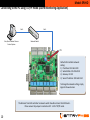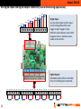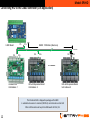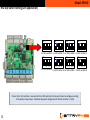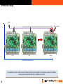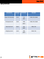
1
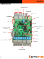
Wiring Guide
EP.HIO
Version 1.03
1
Last Updated: 14-10-2014
Model: EP.HIO
Note:
See http://www.entrypass.net/ for updates, revisions, and download the latest installation manual
Platform1 version 3 support 6 and 10 digits format
For existing site, P1 will detect its card database to determine 6 or 10 digits; For new site, user can change
the digits as long as the card database is empty
Please refer to separate EntryPass Platform1 User Manual for detail operation help. The Official EntryPass
Platform1 User Manual can be downloaded from our website under “Download” section
2
Model: EP.HIO
Before you begin
Technical Support
If you cannot find the answer to your question in this manual or in the Help files, we recommend you
contact your system installer. Your installer is familiar with your system configuration and should be able
to answer any of your questions.
Should you need additional information, please call our Technical Support Help desk, Monday to Friday
9:00 AM to 6:00 PM (GMT +8:00)
Method Details
Phone + 60 (3) - 8068 1929
Fax + 60 (3) - 8068 1922
Internet www.entrypass.net
Email [email protected]
3
Model: EP.HIO
Considerations Prior to Installation
Preparing Your EntryPass Controllers
EntryPass controller contains numerous delicate electronic circuits and components which can become damaged
as a result of electrostatic discharge (ESD). Thus, prior to installation, please follow the instruction below:
•Observe precautions while handling the circuit board assembly by using proper grounding straps and handling
precautions at all
•Visually ensure no onboard parts is broken, damage or contains burn mark
•Do not turn on the power supply until you completed all wiring and external add on devices installations
CAUTION
Battery may explode if mistreated. Do not recharge, disassemble
or dispose of in fire. To prevent a risk of explosion do not pry the
battery out with a metal or conductive tool.
Instances of Non-Warranty
•Damage due to natural disaster, accident or human cause.
•Damage as a result of violating the conditions recommended in the user manual
•Damage due to improper installation
•Damage due to use of uncertified components
•Damage due to use exceeding the permitted parameters
4
Model: EP.HIO
Component Description
Communication Connector
Digital Input Connecter
Communication LED
RJ-45 Network Port
Digital Output LED
Heartbeat LED
Digital Input LED
Dip switch
IDE Connector For Daughter Board
Expansion
Power Connector For Daughter
Board Expansion
32-Bits Processor
Power Connector
Backup Battery
Cold Start Button
Onboard Power LED (5V and 3.3V)
Reset Button
Digital Output Connecter
5
Model: EP.HIO
Component Description (With expansion board)
Digital Input Connecter
Digital Output LED
Digital Input LED
Expansion board
power cables
Digital Output Connecter
With the expansion board attached to the HIO controller, the HIO now support 16 Digital Inputs and 16 Digital Outputs
6
Model: EP.HIO
Power Supply Unit Specification
ENTRYPASS
Power Supply Unit Specification:
• Switching Power Supply
• 12V DC
• 3 Amp (Minimum)
7
Model: EP.HIO
Connecting to the PC using RS 485 mode (Alarm Monitoring Application)
C2-
HIO 16
Ensure the dip switch
setting is unique when
there is more than 1 HIO
controller
C2 +
C2-
C2 +
C2-
HIO 2
C2 +
HIO 1
RS 485: I000 meter (Maximum)
CC+
PCC
(Pc Communicator)
When in RS485 mode, a total of 16 sets HIO controllers can be connected to each
bus/comport.
8
Rx
Tx
Power
EntryPass Platform1
Server Access
Control System
RS232
RS 232: 10 meter
Model: EP.HIO
HIO Dip Switch Setting (Alarm Monitoring Application)
ON
ON
ON
ON
1 2 3 4 5
1 2 3 4 5
1 2 3 4 5
1 2 3 4 5
For HIO number 1
For HIO number 2
For HIO number 3
For HIO number 4
ON
ON
ON
ON
1 2 3 4 5
1 2 3 4 5
1 2 3 4 5
1 2 3 4 5
For HIO number 5
For HIO number 6
For HIO number 7
For HIO number 8
ON
ON
ON
ON
1 2 3 4 5
1 2 3 4 5
1 2 3 4 5
1 2 3 4 5
For HIO number 9
For HIO number 10
For HIO number 11
For HIO number 12
ON
ON
ON
ON
1 2 3 4 5
1 2 3 4 5
1 2 3 4 5
1 2 3 4 5
For HIO number 13
For HIO number 14
For HIO number 15
For HIO number 16
If more than 1 HIO controller is connected to the PCC, the dip switch must be configure according to the pattern
shown above. The default dip switch configuration of the HIO controller is 1 (ON)
9
Model: EP.HIO
Connecting to the PC using TCP/IP mode (Alarm Monitoring Application)
Cat-5
Cat-5
EntryPass Platform1 Access
Control System
Network Switch
JP1
Default HIO controller network
setting:
1) IP address: 192.168.1.100
2) Subnet Mask: 255.255.255.0
3) Gateway: 0.0.0.0
4) Server IP address: 192.168.1.254
To change the network setting, simply
logon to the web server.
The distance from HIO controller to network switch should not more than 100 meter .
Please ensure the jumper is inserted on JP1 3-4 for TCP/IP mode.
10
Model: EP.HIO
HIO digital input and digital output connector (Alarm Monitoring Application)
Input 8
Input 7
Input 6
Digital Input:
Is a dry contact point and the input
can be configurable either close
trigger or open trigger to suits
different contact devices such as PIR,
magnetic sensor, vibration sensor,
smoke sensor and etc
Input 5
Input 4
Input 3
Input 2
Input 1
IN1
IN2
GND
IN3
IN4
GND
IN5
IN6
GND
IN7
IN8
GND
Digital Output:
Selectable output either in normally
close or normally open connection.
NC1
CM1 NO1 NC2
Output 1
11
CM2 NO2
Output 2
NC3
CM3 NO3 NC4
Output 3
CM4 NO4
Output 4
NC5
CM5 NO5 NC6
Output 5
CM6 NO6
Output 6
NC7
CM7 NO7 NC8
Output 7
CM8 NO8
Output 8
Model: EP.HIO
Connecting HIO to the L3800 controller (Lift Application)
L3800 Board
C1-
C1+
RS485: 1000 Meter (Maximum)
Terminator
C2-
C2+
C2-
C2+
C2-
C2+
……
On-Board HIO
Unit Address: 1
HIO with Expansion Board
Unit Address: 2
HIO with Expansion Board
Unit Address: 9
The On-Board HIO is shipped in package with L3800
Is advisable to connect a resistor (100 Ohm) as terminator on last HIO
Other HIO boards must loop from ON-board HIO C2+/C2-
12
Model: EP.HIO
HIO Dip Switch Setting (Lift Application)
ON
1 2 3 4 5
ON
1 2 3 4 5
ON
1 2 3 4 5
ON
1 2 3 4 5
For HIO number 1 For HIO number 2 For HIO number 3 For HIO number 4
ON
1 2 3 4 5
ON
1 2 3 4 5
ON
1 2 3 4 5
ON
1 2 3 4 5
For HIO number 5 For HIO number 6 For HIO number 7 For HIO number 8
If more than 1 HIO controller is connected to the L1000 controller, the dip switch must be configure according
to the pattern shown above. The default dip switch configuration of the HIO controller is 1 (ON)
13
Model: EP.HIO
5
6
NC8
CM8
NO8
4
NC7
CM7
NO7
3
NC5
CM5
NO5
NC6
CM6
NO6
2
NC3
1
CM3
NO3
NC4
CM4
NO4
CM2
NO2
NC1
CM1
NO1
NC2
HIO Output Connector (Lift Application)
7
8
You can select the HIO output either in normally open state (NO) or
normally close state (NC) and this HIO output connection is connected to
the Lift Controller (floor button location). Thus, 1 HIO (without expansion
board) can control up to 8 floors (Due to the 8 outputs available)
14
Model: EP.HIO
HIO Output Connector - With expansion board (Lift Application)
NC16
CM16
NO16
8
NC15
CM15
NO15
7
NC14
CM14
NO14
6
NC13
CM13
NO13
5
NC12
CM12
NO12
4
NC11
CM11
NO11
3
NC10
CM10
NO10
2
NC9
CM9
NO9
1
9
10
11
12
13
14
15
16
You can select the HIO output either in normally open state (NO) or
normally close state (NC) and this HIO output connection is connected to
the Lift Controller (floor button location). Thus, 1 HIO (with expansion
board) can control up to 16 floors (Due to the 16 outputs available)
15
Model: EP.HIO
Performing Cold Start
JP1
Digital Input LED
Cold Start Button
Reset Button
Steps of performing cold start:
1.
2.
3.
4.
5.
6.
7.
8.
16
Please ensure that the jumper is inserted on JP1 1-2
Press Cold Start Button
Hold the Cold Start Button and press Reset Button
Release Reset Button and hold the Cold Start Button
Hold the Cold Start Button for about 2 sec
Release the Cold Start Button
All the 8 Digital Inputs LED will turn ON
When the process is complete, all the inputs LED will
turn OFF
Model: EP.HIO
Performing Factory Default
JP1
Digital Input LED
Cold Start Button
Reset Button
Steps of performing factory default:
1.
2.
3.
4.
5.
6.
7.
8.
Please ensure that the jumper is inserted on JP1 11-12
Press Cold Start Button
Hold the Cold Start Button and press Reset Button
Release Reset Button and hold the Cold Start Button
Hold the Cold Start Button for about 2 sec
Release the Cold Start Button
All the 8 Digital Inputs LED will turn ON
When the process is complete, all the inputs LED will
turn OFF
Factory Default will change the IP Address back to 192.168.1.100, Server IP to 192.168.1.254 and Port to 2020
17
Termination Setting
ToL1000
PCC
To
100 ohm resistor
C2-
HIO 1
C2+
C2-
C2+
HIO 2
C2-
C2+
HIO
168
HIO
RS 485: 1000 meter (Maximum)
It is advisable to insert a resistor value of 100 ohm on the last HIO controller for termination purpose if installation
involve long communication distance or multiple units of HIO
18
Model: EP.HIO
Cabling Information
19
Communication
Data Signal
Max Distance
Description
Computer to PC Communicator
RS 232
10m
(30 ft)
22 AWG, 2 Pairs, Shielded
PC Communicator to HIO
RS 485
1000m
(3000 ft)
22 AWG, 2 Pairs, Shielded
Network Switch to HIO
Network
100m
(300 ft)
24AWG, 4 Pairs
HIO digital input contact
Contact
1000m
(3000 ft)
24 AWG, 1 Pairs