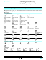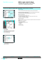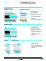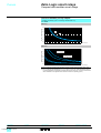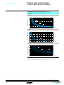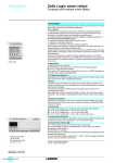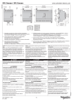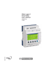
1
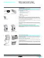
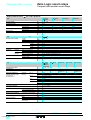
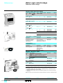
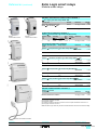
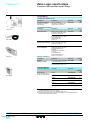
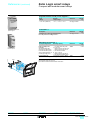
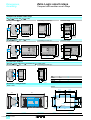
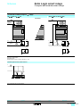
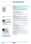
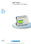
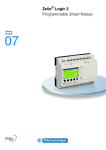
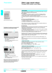
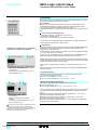
Presentation
6
Zelio Logic smart relays
6
Compact and modular smart relays
109446
Presentation
Zelio Logic smart relays are designed for use in small automated systems. They are
used in both the industrial and commercial sectors.
b For industry:
v automation of small finishing, production, assembly or packaging machines.
v decentralised automation of ancillary equipment of large and medium-sized
machines (textile, plastics, materials processing sectors etc.),
v automation systems for agricultural machinery (irrigation, pumping, greenhouses
etc.).
b
v
v
v
Zelio Logic compact smart relay
For the commercial/building sectors:
automation of barriers, roller shutters, access control,
automation of lighting systems,
automation of compressors and air conditioning systems.
Their compact size and ease of setting-up make them a competitive alternative to
solutions based on cabled logic or specific cards.
Combination of modular smart relays with I/O
extension and communication modules
2
109458
1
b Programming
Simple programming, ensured by the universal nature of the languages, meets all the
requirements of automation specialists and also the needs of the electrician.
Programming can be performed:
v independently, using the buttons on the Zelio Logic smart relay (ladder language),
v on a PC using “Zelio Soft 2” software.
When using a PC, programming can be performed either in LADDER language or in
function block diagram (FBD) language, see pages 14102/4 to 14102/8.
Backlighting of the LCD display (1) is obtained by activating one of the 6 programming
buttons on the Zelio Logic smart relay or by programming with “Zelio Soft 2” software
(example: flashing in the event of a malfunction).
1 Zelio Logic modular smart relay
(10 or 26 I/O)
2 I/O extension module: discrete (6, 10 or 14
I/O) or analogue (4 I/O)
1
2
The autonomous operating time of the clock, assured by a lithium battery, is 10
years.
Data backup (preset values and current values) is provided by an EEPROM Flash
memory (10 years).
Compact smart relays
Compact smart relays meet requirements for simple automation systems.
The number of inputs/outputs can be:
b 12 or 20 I/O, supplied with a 24 V or c 12 V,
b 10, 12 or 20 I/O, supplied with a 100…240 V or c 24 V.
3
000003-26
Modular smart relays and extensions
The number of inputs/outputs for modular smart relays can be:
b 26 I/O, supplied with c 12 V,
b 10 or 26 I/O, supplied with a 24 V, a 100…240 V or c 24 V
1 Zelio Logic modular smart relay
(10 or 26 I/O)
2 Modbus or Ethernet communication
modules
3 I/O extension module: discrete (6, 10 or 14
I/O) or analogue (4 I/O)
d The order shown above must be observed when using
To improve performance and flexibility, Zelio Logic modular smart relays can be fitted
with communication modules and I/O extension modules to obtain a maximum of
40 I/O:
b Modbus or Ethernet communication modules, supplied with c 24 V via the
Zelio Logic smart relay at the same voltage.
b analogue I/O extension modules with 4 I/O, supplied with c 24 V via the
Zelio Logic smart relay at the same voltage,
b discrete I/O extension modules with 6, 10 or 14 I/O, supplied via the Zelio Logic
smart relay at the same voltage.
(1) LCD: Liquid Crystal Display.
a Modbus slave or Ethernet server communication
module and a discrete or analogue I/O extension module.
An I/O extension module cannot be fitted before the
Modbus slave communication module.
Functions :
pages 14102/6 to 14102/8
14102-EN_Ver5.0.fm/2
Characteristics:
pages 14102/10 to 14102/15
Curves :
pages 14102/16 and 14102/17
References:
pages 14102/18 to 14102/23
Dimensions, schemes:
pages 14102/24 to 14102/27
Presentation (continued)
6
Zelio Logic smart relays
6
Compact and modular smart relays
Cabled and wireless programming tools
b These programming tools allow the Zelio Logic smart relay to be connected to a
PC running “Zelio Soft 2” software:
v Link by cables:
- Cable SR2 CBL01 to 9-pin serial port
or
- Cable SR2 USB01 to USB port
536135
523409
Communication
Connecting cable
Bluetooth interface
534944
v Wireless link:
- Bluetooth interface SR2 BTC01
b Memory cartridge
The Zelio Logic smart relay can be fitted with a backup memory cartridge which
enables the application program to be copied into another Zelio Logic smart relay.
However, loading and updating of the firmware (software embedded in the product)
is only possible with memory cartridge SR2 MEM02.
Memory cartridge
The memory cartridge also enables a backup copy of the program to be saved prior
to replacing the product.
Modbus slave and Ethernet server communication modules
Modbus and Ethernet communication modules allow connection to automation
system equipment such as display units or programmable controllers (see pages
14105/2 to 14105/11).
536136
540454
When used with a smart relay without display or buttons, the copy of the program
contained in the cartridge is automatically transferred into the Zelio Logic smart relay
on power-up.
Ethernet
communication module
Modem communication interface
The “Modem communication interface” products in the Zelio Logic range include:
b a Modem communication interface SR2 COM01 connected between a Zelio Logic
smart relay and a Modem,
b analogue (PSTN) Modems (1) SR2 MOD01 or GSM Modem (2) SR2 MOD02,
b “Zelio Logic Alarm” software SR2 SFT02.
534941
534943
Modbus
communication module
534942
Analogue
PSTN Modem
Modem
communication interface
Functions :
pages 14102/6 to 14102/8
GSM Modem
Characteristics:
pages 14102/10 to 14102/15
They are designed for monitoring or remote control of machines or installations which
operate without personnel.
The Modem communication interface supplied with c 12...24 V, enables messages,
telephone numbers and calling conditions to be stored, see pages 14104/2 to 14104/
11.
(1) Public Switched Telephone Network.
(2) Global System Mobile.
Curves :
pages 14102/16 and 14102/17
References:
pages 14102/18 to 14102/23
Dimensions, schemes:
pages 14102/24 to 14102/27
14102-EN_Ver5.0.fm/3
Presentation
6
Zelio Logic smart relays
Compact and modular smart relays
“Zelio Soft 2” programming software
“Zelio Soft 2” for PC (versions u 4.1)
“Zelio Soft 2” software enables:
b programming in LADDER language or in function block diagram (FBD) language,
see pages 14102/6 to 14102/8,
b simulation, monitoring and supervision,
b uploading and downloading of programs,
b output of personalised files,
b automatic compiling of programs,
b on-line help.
Programming in LADDER language
Coherence tests and application languages
“Zelio Soft 2” software monitors applications by means of its coherence test function.
An indicator turns red at the slightest input error. The problem can be located by
simply clicking the mouse.
“Zelio Soft 2” software allows switching, at any time, to any of the 6 languages
(English, French, German, Spanish, Italian, Portuguese) and editing of the
application file in the selected language.
Inputting messages for display on Zelio Logic
“Zelio Soft 2” software allows Text function blocks to be configured, which can then
be displayed on all Zelio Logic smart relays which have a display.
Program testing
2 test modes are provided:
b “Zelio Soft 2” simulation mode allows a program to be tested without a Zelio
Logic smart relay, i.e.:
v enable discrete inputs,
v display the status of outputs,
v vary the voltage of the analogue inputs,
v enable the programming buttons,
v simulate the application program in real time or in accelerated time,
v dynamically display (in red) the various active elements of the program.
Programming in FBD language
b “Zelio Soft 2” monitoring mode makes it possible to test the program executed by
the smart relay, i.e.:
v display the program “on-line”,
v force inputs, outputs, control relays and current values of the function blocks,
v adjust the time,
v change from STOP mode to RUN mode and vice versa.
Simulation mode
In simulation or monitoring mode, the monitoring window allows the status of the
smart relay I/Os to be displayed within your application environment (diagram or
image).
Monitoring window
Functions :
pages 14102/6 to 14102/8
14102-EN_Ver5.0.fm/4
Characteristics:
pages 14102/10 to 14102/15
Curves :
pages 14102/16 and 14102/17
References:
pages 14102/18 to 14102/23
Dimensions, schemes:
pages 14102/24 to 14102/27
6
Presentation (continued)
6
Zelio Logic smart relays
6
Compact and modular smart relays
“Zelio Soft 2” programming software
User interfaces
Version 4.1 of "Zelio Soft 2" software improves, amongst other things, the ease of
use of user interfaces for the following functions:
"Split wiring sheet" function (FBD language)
The wiring sheet can be split into 2. Splitting allows two separate parts of the wiring
sheet to be displayed on the same screen.
1
2
3
4
5
6
7
This makes it possible to:
b Display the required function blocks in the top and bottom parts.
b Move the split bar as required.
b Connect the function blocks between the 2 parts of the wiring sheet.
The split wiring sheet is structured as follows:
1 View of top part
2 Top window vertical scroll bar
3 Top window horizontal scroll bar
4 Split bar
5 View of bottom part
6 Bottom window vertical scroll bar
7 Bottom window horizontal scroll bar
Structure of a split wiring sheet
"Replacement of a function block" (FBD language)
A function allows a block to be replaced without losing the input and output
connections.
E.g.: Replacement of an "OR" block by a "NOR" block.
Waiting
1
1 "OR" block to be replaced
2
zzzz
3
2 Move all links to the new "NOR" block
3 Delete the "OR" block and position
the "NOR" block in its place
"Time Prog Simulation" function (LADDER and FBD languages)
LADDER or FBD program simulation mode allows the program to be debugged by
simulating it on the software workshop host computer.
A function allows the time on the simulator clock to be modified by setting to 3
seconds before the start of the next event.
The “Next event” button 1 allows modification of the simulator clock 2.
2
1
“Acceleration and simulation terminals" window"
Functions :
pages 14102/6 to 14102/8
Characteristics:
pages 14102/10 to 14102/15
Curves :
pages 14102/16 and 14102/17
References:
pages 14102/18 to 14102/23
Dimensions, schemes:
pages 14102/24 to 14102/27
14102-EN_Ver5.0.fm/5
Functions
6
Zelio Logic smart relays
Compact and modular smart relays
“Zelio Soft 2” programming software
LADDER language
Definition
Text function block
Up/down counter
Analogue comparator
Control relay
LCD backlighting
Output coil
LADDER language enables a LADDER program to be written with elementary
functions, elementary function blocks and derived function blocks, as well as with
contacts, coils and variables.
The contacts, coils and variables can be annotated. Text can be placed freely within
Timer
the graphic.
b Control scheme input modes
“Zelio input” mode enables users who have directly programmed the Zelio Logic
smart relay to find the same user interface, even when using the software for the first
time.
Fast counter
“Free input” mode, which is more intuitive, is very user-friendly and incorporates
many additional features.
With LADDER programming language, two alternative types of symbol can be used:
v LADDER symbols,
v electrical symbols.
Clock
“Free input” mode also allows the creation of mnemonics and notes associated with
each line of the program.
Instant switching from one input mode to the other is possible at any time, by simply
clicking the mouse.
Up to 120 control scheme lines can be programmed, with 5 contacts and 1 coil per
Counter comparator
program line
b Functions:
v 16 Text function blocks,
v 16 time delay function blocks; parameters of 11 different types can be set for each
th
Summer/Winter time switching of these (1/10 second to 9999 hours),
v 16 up/down counter function blocks from 0 to 32767,
v 1 fast counter (1 kHz),
v 16 analogue comparator function blocks,
v 8 clock function blocks, each with 4 channels,
v 28 control relays,
Message
v 8 counter comparators,
v LCD screen with programmable backlighting,
v automatic Summer/Winter time switching,
v variety of functions: coil, latching (Set/Reset), impulse relay, contactor,
v 28 message blocks (with communication interface, see page 14104/2).
Functions
22
or
14
LADDER language
21
Electrical scheme
13
Function
Contact
I
or
Notes
I corresponds to the real state of the contact connected to the
input of the smart relay.
i corresponds to the inverse state of the contact connected to the
input of the smart relay.
i
The coil is energised when the contacts to which it is connected
are closed.
A2
A1
Standard coil
S
The coil is energised (set) when the contacts to which it is
connected are closed.
It remains set even if the contacts are no longer closed.
R
The coil is de-energised (reset) when the contacts to which it is
connected are closed.
It remains disabled even if the contacts are no longer closed.
A2
Unlatch coil
(Reset)
A1
A2
A1
Latch coil (Set)
Presentation:
pages 14102/2 to 14102/5
14102-EN_Ver5.0.fm/6
Characteristics:
pages 14102/10 to 14102/15
Curves :
pages 14102/16 and 14102/17
References:
pages 14102/18 to 14102/23
Dimensions, schemes:
pages 14102/24 to 14102/27
6
Functions (continued)
6
Zelio Logic smart relays
6
Compact and modular smart relays
“Zelio Soft 2” programming software
Function block diagram language (FBD / Grafcet SFC / Logic functions) (1)
Definition
FBD language allows graphical programming based on the use of predefined function blocks; it provides the use of:
b 32 functions for counting, time delay, timing, definition of switching threshold, (for example: temperature regulation), generation of impulses,
time programming, multiplexing, display,
b 7 SFC functions,
b 6 logic functions.
Pre-programmed functions
Zelio Logic smart relays provide a high processing capacity, up to 200 function blocks, including 32 pre-programmed functions:
TIMER AC
TIMER BH
TIMER Li
TIMER BW
Timer. Function A/C
(ON-delay and OFF-delay)
Timer. Function BH.
(adjustable pulsed signal)
Pulse generator
(ON-delay, OFF-delay)
Timer. Function A/C with
external preset adjustment
(ON-delay and OFF-delay)
BISTABLE
Timer. Function BH with
external preset adjustment
(adjustable pulsed signal)
SET- RESET
Pulse generator
with external preset adjustment
(ON-delay, OFF-delay)
BOOLEAN
Impulse relay function
Bistable latching - Priority
assigned either to SET or
RESET function
PRESET H-METER
Allows logic equations to be
created between connected
inputs
TIME PROG
Cam programmer
Hour counter
(hour, minute preset)
Time programmer, weekly
and annual.
Defines an activation zone
with hysteresis
ADD/SUB
Allows conversion of an
analogue value by change of
scale and offset.
MUL/DIV
Zone comparison
(Min. y Value y Max.)
Add and/or subtract function
Multiply and/or divide function
COM
COMPARE
Display of 4 pieces of data:
digital, analogue, date, time,
messages for HumanMachine interface.
ARCHIVE
UP DOWN COUNT
Up/down counter with external
preset
MUX
Multiplexing functions on
2 analogue values
COMP IN ZONE
DISPLAY
Timer. Function BW
(pulse on rising/falling edge)
CAM
PRESET COUNT
GAIN
TRIGGER
STATUS
Display of digital and analogue Sending of messages with
data, date, time, messages for communication interface
Human-Machine interface.
(see page 14104/2)
SPEED COUNT
CAN
Comparison of 2 analogue
values using the operands
=, >, <, y, u.
CNA
Access to smart relay status
Fast counting up to
1 kHz
Digital/analog converter
Input of a word via serial link
STEP
DIV-OR 2
Analog/digital converter
Up/down counter
SL In
TEXT
Storage of 2 values
simultaneously
SL Out
Output of a word via serial
link
SFC functions (2) (GRAFCET)
RESET-INIT
INIT STEP
Reinitialisable step
DIV-AND 2
Initial step
CONV-AND 2
Divergence to AND
Convergence to AND
SFC step
Divergence to OR
CONV-OR 2
Convergence to OR
Logic functions
AND
OR
AND function
OR function
(1) Functional Block Diagram
(2) Sequential Function Chart.
Presentation:
pages 14102/2 to 14102/5
NAND
NOT AND function
Characteristics:
pages 14102/10 to 14102/15
NOR
NOT OR function
Curves :
pages 14102/16 and 14102/17
XOR
Exclusive OR function
References:
pages 14102/18 to 14102/23
NOT
NOT function
Dimensions, schemes:
pages 14102/24 to 14102/27
14102-EN_Ver5.0.fm/7
Functions (continued)
6
Zelio Logic smart relays
Compact and modular smart relays
“Zelio Soft 2” programming software
Function block diagram language (FBD / Grafcet SFC / Logic functions) (continued)
Macro Function
A Macro is a grouping of function blocks. It is characterised by its number, its name,
its links, its internal function blocks (255 max.) and by its I/O connections.
Seen from the outside, a Macro behaves like a function block with inputs and/or
outputs that can be connected to links.
Once created, a Macro can be manipulated like a function block.
b
v
v
v
v
Creation of a Macro
1
5
2
3
4
6
Macro characteristics:
The maximum number of Macros is 64.
A password dedicated to Macros can be used to protect their content,
A Macro can be edited / duplicated,
A Macro's comments can be edited.
b Macro properties:
A "Macro properties" dialogue box allows the properties of a Macro to be entered or
edited.
The properties of a Macro are:
v Macro name (optional)
v The block Symbol, which may be:
- an identifier,
- an image.
v Name of inputs.
v Name of outputs.
Inside of a Macro
1
2
3
4
5
6
Macro selection
Edit properties
Allows return to external view of a Macro
Internal function block within the Macro
Non connected inputs
Non connected outputs
1
2
Outside of a Macro
1 Input connections
2 Output connection
Presentation:
pages 14102/2 to 14102/5
14102-EN_Ver5.0.fm/8
Characteristics:
pages 14102/10 to 14102/15
Curves :
pages 14102/16 and 14102/17
References:
pages 14102/18 to 14102/23
Dimensions, schemes:
pages 14102/24 to 14102/27
6
Description
6
Zelio Logic smart relays
6
Compact and modular smart relays
Compact smart relays
With display - 10, 12 and 20 I/O
1 2
Without display - 10, 12 and 20 I/O
3
1
2
3
4
5
5
7
6
7
1
Zelio Logic compact smart relays have the
following on their front panel:
1 Two retractable fixing lugs.
2 Two power supply terminals.
3 Terminals for connection of the inputs.
4 Backlit LCD display with 4 lines of 18
characters.
5 Slot for memory cartridge or connection
to a PC or Modem communication
interface.
6 6 buttons for programming and
parameter entry.
7 Terminals for connection of the outputs.
1
Modular smart relays
With display - 10 and 26 I/O
3
1 2
Zelio Logic modular smart relays have the
following on their front panel:
1 Two retractable fixing lugs.
2 Two power supply terminals.
3 Terminals for connection of the inputs.
4 Backlit LCD display with 4 lines of 18
characters.
5 Slot for memory cartridge or connection
to a PC or Modem communication
interface.
6 6 buttons for programming and
parameter entry.
7 Terminals for connection of the outputs.
4
5
6
7
1
Discrete I/O extension modules
6 discrete I/O
10 and 14 discrete I/O
2
1
4
4
5
5
5
5
3
2
1
1
Presentation, functions:
pages 14102/2 to 14102/8
3
Characteristics:
pages 14102/10 to 14102/15
Discrete I/O extension modules have the
following on their front panel:
1 Two retractable fixing lugs.
2 Terminals for connection of the inputs.
3 Terminals for connection of the outputs.
4 A connector for connection to the Zelio
Logic smart relay (powered via the Zelio
Logic smart relay).
5 Locating pegs.
1
Curves :
pages 14102/16 and 14102/17
References:
pages 14102/18 to 14102/23
Dimensions, schemes:
pages 14102/24 to 14102/27
14102-EN_Ver5.0.fm/9
Characteristics
6
Zelio Logic smart relays
Compact and modular smart relays
General environment characteristics
Type
Product certifications
Conformity with the
low voltage directive
Conformity with the
EMC directive
Degree of protection
Overvoltage category
Degree of pollution
Ambient air temperature
around the device
conforming to IEC 60028-2-1
and IEC 60068-2-2
Maximum relative humidity
Maximum operating altitude
Mechanical resistance
Resistance to
electrostatic discharge
Resistance to HF interference
(immunity)
Conducted and
radiated emissions
Screw terminals connection
capacity
SR2 A / SR2 B / SR2 D / SR2 E / SR3 B / SR3 XT
UL, CSA, GL, C-Tick
EN (IEC) 61131-2 (open equipment)
Conforming to 73/23/EEC
Conforming to 89/336/EEC
Conforming to IEC/EN 60529
Conforming to IEC/EN 60664-1
Conforming to IEC/EN 61131-2
°C
Operation
°C
Storage
Conforming to IEC/EN 60068-2-30
Operation
m
m
Transport
Immunity to vibration
Immunity to mechanical shock
Immunity to
electrostatic discharge
Immunity to electromagnetic
radiated fields
Immunity to fast transients
in bursts
Immunity to shock waves
Radio frequency
in common mode
Voltage dips and breaks (a)
Immunity to damped
oscillation waves
Conforming to EN 55022/11
(Group 1)
Flexible cable with cable end mm2
Semi-solid cable
Solid cable
mm2
mm2
Tightening torque
N.m
EN (IEC) 61131-2 (Zone B)
EN (IEC) 61000-6-2, EN (IEC) 61000-6-3 (1) and EN (IEC) 61000-6-4
IP 20 (terminal block), IP 40 (front panel)
3
2
- 20...+ 55 (+ 40 in non-ventilated enclosure)
- 40...+ 70
95% without condensation or dripping water
2000
3048
IEC/EN 60068-2-6, test Fc
IEC/EN 60068-2-27, test Ea
IEC/EN 61000-4-2, level 3
IEC/EN 61000-4-3
IEC/EN 61000-4-4, level 3
IEC/EN 61000-4-5
IEC/EN 61000-4-6, level 3
IEC/EN 61000-4-11
IEC/EN 61000-4-12
Class B (1)
1 conductor: 0.25...2.5, cable: AWG 24...AWG 14
2 conductors: 0.25...0.75, cable: AWG 24...AWG 18
1 conductor: 0.25...2.5, cable: AWG 25...AWG 14
1 conductor: 0.25...2.5, cable: AWG 25...AWG 14
2 conductors: 0.2...1.5, cable: AWG 24...AWG 16
0.5 (tightened using Ø 3.5 mm screwdriver)
Processing characteristics
Number of control
scheme lines
Number of function blocks
Cycle time
Response time
Back-up time
(in the event of power failure)
With LADDER programming
120
With FBD programming
ms
ms
Day/time
Program and adjustments in
the Zelio Logic smart relay and
in EEPROM memory cartridge
SR2 MEM0p
Program memory checking
Clock drift
Up to 200
6...90
Input acquisition time + 1 to 2 cycle times
10 years (lithium battery) at 25 °C
10 years
On each power-up
12 min/year (0 to 55 °C)
6 sec/month (at 25 °C and calibration)
1% ± 2 of the cycle time
Timer block accuracy
(1) Except for configuration SR3 BpppBD + SR3 MBU01BD + SR3 XT43BD or
SR3 BpppBD + SR3 NET01BD + SR3 XT43BD class A (class B: work in progress).
Presentation:
pages 14102/2 to 14102/5
14102-EN_Ver5.0.fm/10
Functions :
pages 14102/6 to 14102/8
Curves :
pages 14102/16 and 14102/17
References:
pages 14102/18 to 14102/23
Dimensions, schemes:
pages 14102/24 to 14102/27
6
Characteristics (continued)
6
Zelio Logic smart relays
6
Compact and modular smart relays
Supply characteristics, a 24 V products
Type
Nominal voltage
Voltage limits
Nominal frequency
Nominal input current
Power dissipated
Micro-breaks
rms insulation voltage
Without extensions
With extensions
Without extensions
With extensions
Permissible duration
V
V
Hz
mA
mA
VA
VA
ms
V
SR2 p121B
SR2 p201B
a 24
a 20.4…28.8
50-60
145
233
–
4
6
–
y 10 (repeated 20 times)
a 1780
SR3 B101B
SR3 B261B
160
280
4
7.5
280
415
7.5
10
Discrete input characteristics, a 24 V products
Type
Nominal value of inputs
Input switching limit values
Voltage
Current
Frequencies
At state 1
At state 0
Input impedance at state 1
Response
LADDER
time
language
FBD
language
Isolation
Protection
Voltage
Current
Voltage
Current
State 0 to 1 (50/60 Hz)
State 1 to 0 (50/60 Hz)
State 0 to 1 (50/60 Hz)
State 1 to 0 (50/60 Hz)
Between supply and inputs
Between inputs
Against inversion of terminals
V
mA
Hz
V
mA
V
mA
kΩ
ms
ms
ms
ms
SRp ppppB
a 24
4,4
47...53 and 57...63
u a 14
>2
ya 5
< 0.5
4.6
50
50
50 min., 255 max. (in increments of 10)
50 min., 255 max. (in increments of 10)
None
None
Yes (control instructions not executed)
Relay output characteristics, a 24 V products
Type
V
Operating limit values
Contact type
Thermal current
Electrical durability for
500 000 operating cycles
Conforming to
IEC/EN 60947-5-1
Minimum switching capacity
Low power switching
reliability of contact
Maximum operating rate
Mechanical life
Rated impulse withstand
voltage (Uimp)
Response time
Built-in protection
Presentation:
pages 14102/2 to 14102/5
A
SR2 p121B
SR2 p201B
SR3 B101B
SR3 XT101B
c 5...30, a 24...250
N/O
4 outputs: 8 A 8 outputs: 8 A
V
A
DC-13
V
A
AC-12
V
A
AC-15
V
A
At minimum voltage of c 12 V mA
c 24
1.5
c 24 (L/R = 10 ms)
0.6
a 230
1.5
a 230
0.9
10
c 12 V - 10 mA
No-load
At Ie (operational current)
In millions of operating cycles
Conforming to IEC/EN 60947-1
and IEC/EN 60664-1
Set
Reset
Against short-circuits
Against overvoltage
and overload
10
0.1
10
4
Utilisation
category
DC-12
Functions :
pages 14102/6 to 14102/8
Hz
Hz
kV
ms
ms
SR3 B261B
SR3 XT61B
SR3 XT141B
8 outputs: 8 A
2 outputs: 5 A
2 outputs: 8 A
4 outputs: 8 A
2 outputs: 5 A
10
5
None
None
Curves :
pages 14102/16 and 14102/17
References:
pages 14102/18 to 14102/23
Dimensions, schemes:
pages 14102/24 to 14102/27
14102-EN_Ver5.0.fm/11
Characteristics (continued)
6
Zelio Logic smart relays
6
Compact and modular smart relays
Supply characteristics, a 100...240 V products
Type
Nominal voltage
Voltage limits
Nominal frequency
Nominal input current
Power dissipated
Micro-breaks
rms insulation voltage
Without extensions
With extensions
Without extensions
With extensions
Permissible duration
V
V
Hz
mA
mA
VA
VA
ms
V
SR2 p101FU
SR2 p121FU
a 100…240
a 85…264
50-60
80/30
–
7
–
10
a 1780
SR2 p201FU
SR3 B101FU
SR3 B261FU
100/50
80/30
80/40
7
12
100/50
80/60
12
17
11
Discrete input characteristics, a 100...240 V products
Type
Nominal value of inputs
Input switching limit values
Voltage
Current
Frequencies
At state 1
At state 0
Input impedance at state 1
Response
LADDER
time
language
FBD
language
Isolation
Protection
Voltage
Current
Voltage
Current
State 0 to 1 (50/60 Hz)
State 1 to 0 (50/60 Hz)
State 0 to 1 (50/60 Hz)
State 1 to 0 (50/60 Hz)
Between supply and inputs
Between inputs
Against inversion of terminals
V
mA
Hz
V
mA
V
mA
kΩ
ms
ms
ms
ms
SRp ppppFU
a 100... 240
0.6
47...53 and 57...63
u a 79
> 0.17
y a 40
< 0.5
350
50
50
50 min... 255 max. (in increments of 10)
50 min...255 max. (in increments of 10)
None
None
Yes (control instructions not executed)
Relay output characteristics, a 100...240 V products
Type
Operating limit values
Contact type
Thermal current
Electrical durability for
500 000 operating cycles
Conforming to
IEC/EN 60947-5-1
Minimum switching capacity
Low power switching
reliability of contact
Maximum operating rate
Mechanical life
Rated impulse withstand
voltage (Uimp)
Response time
Built-in protection
Presentation:
pages 14102/2 to 14102/5
14102-EN_Ver5.0.fm/12
V
A
SR2 p101FU
SR2 p201FU
SR2 p121FU
SR3 B101FU
SR3 XT101FU
c 5...30. a 24...250
N/O
4 outputs: 8 A 8 outputs: 8 A
V
A
V
DC-13
A
AC-12
V
A
AC-15
V
A
At minimum voltage of c 12 V mA
c 24
1.5
c 24 (L/R = 10 ms)
0.6
a 230
1.5
a 230
0.9
10
c 12 V - 10 mA
No-load
At Ie (operational current)
In millions of operating cycles
Conforming to IEC/EN 60947-1
and IEC/EN 60664-1
Set
Reset
Against short-circuits
Against overvoltage
and overload
10
0.1
10
4
Utilisation
category
DC-12
Functions :
pages 14102/6 to 14102/8
Hz
Hz
kV
ms
ms
SR3 B261FU
SR3 XT61FU
SR3 XT141FU
8 outputs: 8 A
2 outputs: 5 A
2 outputs: 8 A
4 outputs: 8 A
2 outputs: 5 A
10
5
None
None
Curves :
pages 14102/16 and 14102/17
References:
pages 14102/18 to 14102/23
Dimensions, schemes:
pages 14102/24 to 14102/27
Characteristics (continued)
6
Zelio Logic smart relays
6
Compact and modular smart relays
Supply characteristics, c 12 V products
Type
Nominal voltage
Voltage limits
Nominal input current
Power dissipated
Micro-breaks
Protection
Including ripple
Without extensions
With extensions
Without extensions
With extensions
Permissible duration
Against reversed polarity
V
V
mA
mA
W
W
ms
SR2 B121JD
c 12
c 10.4…14.4
120
–
1.5
–
y 1 (repeated 20 times)
Yes
SR2 B201JD
SR3 B261JD
200
250
400
3
5
2.5
Discrete input characteristics, c 12 V products
Type
Nominal value of inputs
Input switching
limit values
Voltage
Current
At state 1
At state 0
Voltage
Current
Voltage
Current
Input impedance at state 1
Conforming to IEC/EN 61131-2
Sensor compatibility
3-wire
2-wire
Input type
Isolation
Between supply and inputs
Between inputs
Maximum counting frequency
Protection
Against reversed polarity
V
mA
V
mA
V
mA
kΩ
kHz
SRp ppppJD
SRp ppppJD
(inputs I1…IA, IH…IR)
(inputs IB…IG used as discrete inputs)
c 12
4
u c 5.6
u2
y c 2.4
< 0.9
2.7
Type 1
Yes PNP
No
Resistive
None
None
1
Yes (control instructions not executed)
c 12
4
uc7
u 0.5
yc3
< 0.2
14
Type 1
Yes PNP
No
Resistive
None
None
1
Yes (control instructions not executed)
Analogue input characteristics, c 12 V products
Type
Input range
Input impedance
Maximum non destructive voltage
Value of LSB
Input type
Conversion
Resolution
Conversion time
Precision
Repeat accuracy
Isolation
Between analogue channel and supply
Cabling distance
Protection
Against reversed polarity
V
kΩ
V
m
SRp ppppJD (inputs IB…IG used as analogue inputs)
c 0...10 or c 0...12
14
c 14.4
39 mV
Common mode
8 bits at maximum voltage
Smart relay cycle time
± 5 % at 25 °C and ± 6.2 % at 55 °C
± 2 % at 55 °C
None
10 max., with screened cable (sensor not isolated)
Yes
Relay output characteristics, c 12 V products
Type
Operating limit values
Contact type
Thermal current
Electrical durability for
500 000 operating cycles
Conforming to
IEC/EN 60947-5-1
A
SR2 B121JD
SR2 B201JD
SR3 XT101JD
c 5...30, a 24...250
N/O
4 outputs: 8 A 8 outputs: 8 A
V
A
V
A
V
A
V
A
mA
c 24
1.5
c 24 (L/R = 10 ms)
0.6
a 230
1.5
a 230
0.9
10
V
Utilisation category DC-12
DC-13
AC-12
AC-15
Minimum switching
At minimum voltage of c 12 V
capacity
Low power switching reliability of contact
Maximum operating rate No-load
At Ie (operational current)
Mechanical life
In millions of operating cycles
Rated impulse withstand Conforming to IEC/EN 60947-1
voltage (Uimp)
and IEC/EN 60664-1
Response time
Set
Reset
Built-in protection
Against short-circuits
Against overvoltage and overload
Hz
Hz
kV
ms
ms
SR3 B261JD
SR3 XT61JD
SR3 XT141JD
8 outputs: 8 A
2 outputs: 5 A
2 outputs: 8 A
4 outputs: 8 A
2 outputs: 5 A
c 12 V - 10 mA
10
0.1
10
4
10
5
None
None
14102-EN_Ver5.0.fm/13
Characteristics (continued)
6
Zelio Logic smart relays
6
Compact and modular smart relays
Supply characteristics, c 24 V products
Type
Nominal voltage
Voltage limits
Nominal input current
Power dissipated
Micro-breaks
Protection
Including ripple
Without extensions
With extensions
Without extensions
With extensions
Permissible duration
Against reversed polarity
V
V
mA
mA
W
W
ms
SR2
SR2
SR2
p1p1BD B122BD p201BD
c 24
19.2…30
100
–
3
6
–
y 1 (repeated 20 times)
Yes
SR2
SR3
SR3
SR3
SR3
B202BD B101BD B102BD B261BD B262BD
100
3
50
160
4
8
190
300
6
10
70
180
5
Discrete input characteristics, c 24 V products
Type
Nominal value of inputs
Input switching
limit values
Voltage
Current
At state 1
At state 0
Voltage
Current
Voltage
Current
Input impedance at state 1
Conforming to IEC/EN 61131-2
Sensor compatibility
3-wire
2-wire
Input type
Isolation
Between supply and inputs
Between inputs
Maximum counting frequency
Protection
Against reversed polarity
V
mA
V
mA
V
mA
kΩ
kHz
SRp ppppBD
(input I1…IA, IH…IR)
c 24
4
u c 15
u 2.2
yc5
< 0.75
7.4
Type 1
Yes PNP
No
Resistive
None
None
1
Yes (control instructions not executed)
SRp ppppBD
(input IB…IG used as discrete input)
c 24
4
u c 15
u 1.2
yc5
< 0.5
12
Type 1
Yes PNP
No
Resistive
None
None
1
Yes (control instructions not executed)
Analogue input characteristics, c 24 V products
Type
Input range
Input impedance
Maximum non destructive voltage
Value of LSB
Input type
Conversion
Resolution
Conversion time
Precision
Repeat accuracy
Isolation
Between analogue channel and
supply
Cabling distance
Protection
Against reversed polarity
Presentation:
pages 14102/2 to 14102/5
14102-EN_Ver5.0.fm/14
Functions :
pages 14102/6 to 14102/8
V
kΩ
V
m
SRp ppppBD (input IB…IG used as analogue inputs)
c 0...10 or c 0...24
12
c 30
39 mV
Common mode
8 bits at maximum voltage
Smart relay cycle time
± 5 % at 25 °C and ± 6.2 % at 55 °C
± 2 % at 55 °C
None
10 maximum, with screened cable (sensor not isolated)
Yes
Curves :
pages 14102/16 and 14102/17
References:
pages 14102/18 to 14102/23
Dimensions, schemes:
pages 14102/24 to 14102/27
Characteristics (continued)
6
Zelio Logic smart relays
6
Compact and modular smart relays
Relay output characteristics, c 24 V products
Type
Operating limit values
Contact type
Thermal current
Electrical durability for
500 000 operating cycles
Conforming to
IEC/EN 60947-5-1
V
A
Utilisation
category
DC-12
DC-13
AC-12
AC-15
Minimum switching capacity
Low power switching
reliability of contact
Maximum operating rate
Mechanical life
Rated impulse withstand
voltage (Uimp)
Response time
Built-in protection
At minimum voltage of c 12 V
No-load
At Ie (operational current)
In millions of operating cycles
Conforming to IEC/EN 60947-1
and IEC/EN 60664-1
Set
Reset
Against short-circuits
Against overvoltage
and overload
SR2 p101BD
SR2 p201BD
SR2 p121BD
SR3 B101BD
SR3 XT101BD
c 5...30. a 24...250
N/O
4 outputs: 8 A 8 outputs: 8 A
V
A
V
A
V
A
V
A
mA
c 24
1.5
c 24 (L/R = 10 ms)
0.6
a 230
1.5
a 230
0.9
10
c 12 V - 10 mA
Hz
Hz
10
0.1
10
4
kV
ms
ms
SR3 B261BD
SR3 XT61BD
SR3 XT141BD
8 outputs: 8 A
2 outputs: 5 A
2 outputs: 8 A
4 outputs: 8 A
2 outputs: 5 A
10
5
None
None
Transistor output characteristics, c 24 V products
Type
Operating limit values
Load
Residual voltage
Response time
Built-in protection
Nominal voltage
Nominal current
Maximum current
At state 1
Set
Reset
Against overload and
short-circuits
Against overvoltage (1)
Against inversions of
power supply
V
V
A
A
V
ms
ms
SRp Bpp2BD
c 19.2..0.30
c 24
0.5
0.625 at 30 V
y c 2 for I = 0.5 A
y1
y1
Yes
Yes
Yes
(1) If there is no volt-free contact between the Zelio Logic smart relay output and the load.
Presentation:
pages 14102/2 to 14102/5
Functions :
pages 14102/6 to 14102/8
Curves :
pages 14102/16 and 14102/17
References:
pages 14102/18 to 14102/23
Dimensions, schemes:
pages 14102/24 to 14102/27
14102-EN_Ver5.0.fm/15
Curves
6
Zelio Logic smart relays
6
Compact and modular smart relays
Electrical durability of relay outputs
(in millions of operating cycles, conforming to IEC/EN 60947-5-1)
d.c. loads
DC-12 (1)
Millions of operating cycles
3,0
2,5
48 V
2,0
24 V
1,5
1,0
0,5
0,0
0
0,5
1
1,5
2
Current (A)
1
Current (A)
DC-13 (2)
1,4
Millions of operating cycles
L/R = 10 ms 48 V
1,2
L/R = 10 ms 24 V
1,0
L/R = 60 ms 48 V
0,8
L/R = 60 ms 24 V
0,6
0,4
0,2
0,0
0,1
0,2
0,3
0,4
0,5
0,6
0,7
0,8
0,9
(1) DC-12: switching resistive loads and photo-coupler isolated solid-state loads, L/R y 1 ms.
(2) DC-13: switching electromagnets, L/R y 2 x (Ue x Ie) in ms, Ue: rated operational voltage,
Ie: rated operational current (with a protection diode on the load, DC-12 curves must be used
with a coefficient of 0.9 applied to the number in millions of operating cycles).
Presentation:
pages 14102/2 to 14102/5
14102-EN_Ver5.0.fm/16
Functions :
pages 14102/6 to 14102/8
Characteristics:
pages 14102/10 to 14102/15
References:
pages 14102/18 to 14102/23
Dimensions, schemes:
pages 14102/24 to 14102/27
Curves (continued)
6
Zelio Logic smart relays
6
Compact and modular smart relays
Electrical durability of relay outputs (continued)
(in millions of operating cycles, conforming to IEC/EN 60947-5-1)
a.c. loads
AC-12 (1)
Millions of operating cycles
3,0
2,5
24 V
2,0
48 V
1,5
110 V
1,0
230 V
0,5
0,0
0
0,5
1,0
1,5
2,0
2,5
3,0
3,5
4,0
1,2
1,4
1,6
4,5
5
Current (A)
AC-14 (2)
Millions of operating cycles
2,5
2,0
110 V
1,5
230 V
1,0
48 V
24 V
0,5
0,0
0
0,2
0,4
0,6
0,8
1,0
2 Current (A)
1,8
AC-15 (3)
1,0
Millions of operating cycles
0,9
0,8
110 V
0,7
230 V
0,6
48 V
0,5
0,4
0,3
0,2
0,1
0,0
0,5
0,7
0,9
1,1
1,3
1,5
1,7
1,9
Current (A)
(1) AC-12: switching resistive loads and photo-coupler isolated solid-state loads, cos u 0.9.
(2) AC-14: switching small electromagnetic loads y 72 VA, make: cos = 0.3, break: cos = 0.3.
(3) AC-15: switching electromagnetic loads > 72 VA, make: cos = 0.7, break: cos = 0.4.
Presentation:
pages 14102/2 to 14102/5
Functions :
pages 14102/6 to 14102/8
Characteristics:
pages 14102/10 to 14102/15
References:
pages 14102/18 to 14102/23
Dimensions, schemes:
pages 14102/24 to 14102/27
14102-EN_Ver5.0.fm/17
References
6
Zelio Logic smart relays
6
Compact smart relays
109440
Compact smart relays with display
Number Discrete Including
of
inputs c 0-10 V
analogue
I/O
inputs
Relay Transistor Clock
outputs outputs
Reference
Weight
kg
Supply a 24 V
12
20
8
12
0
0
4
8
0
0
Yes
Yes
SR2 B121B
SR2 B201B
0.250
0.380
Supply a 100...240 V
10
6
0
4
0
No
SR2 A101FU (1)
0.250
12
8
0
4
0
Yes
SR2 B121FU
0.250
20
12
0
8
0
No
Yes
SR2 A201FU (1)
SR2 B201FU
0.380
0.380
4
6
4
8
0
0
Yes
Yes
SR2 B121JD
SR2 B201JD
0.250
0.380
536307
SR2 A201BD
Supply c 12 V
12
20
8
12
Supply c 24 V
10
6
0
4
0
No
SR2 A101BD (1)
0.250
12
8
4
4
0
0
4
Yes
Yes
SR2 B121BD
SR2 B122BD
0.250
0.220
20
12
2
6
8
8
0
0
0
8
No
Yes
Yes
SR2 A201BD (1)
SR2 B201BD
SR2 B202BD
0.380
0.380
0.280
536308
SR2 SFT01
“Zelio Soft 2” software for PC
Description
Programming software
“Zelio Soft 2”, multi-language
Application
Reference
For PC, supplied on
CD-ROM (2),compatible with
Windows 98, NT, 2000, XP
SR2 SFT01
Application
Reference
Weight
kg
0.200
Accessories
Connection accessories
Description
Length
Connecting cable
Between the PC
3m
(USB connector)
and the Zelio Logic
smart relay
Other accessories: see pages 14102/22 and 14102/23
536306
SR2 PACKppp
SR2 USB01
Weight
kg
0.100
Compact “discovery” packs
Number Pack contents:
Reference
of
- Compact smart relay with display
I/O
- “Zelio Soft 2” programming software supplied on
CD-Rom
- Cable PC SR2 USB01 for connection to PC(3)
Description of compact smart relay with display
Weight
kg
Supply a 100...240 V
12
20
SR2 B121FU
SR2 B201FU
SR2 PACKFU
SR2 PACK2FU
0.700
0.850
SR2 PACKBD
SR2 PACK2BD
0.700
0.700
Supply c 24 V
12
20
SR2 B121BD
SR2 B201BD
Modem communication interface
Supply c 12...24 V
Description
Modem communication interface
Presentation:
pages 14102/2 to 14102/5
14102-EN_Ver5.0.fm/18
Functions :
pages 14102/6 to 14102/8
Application
Reference
Weight
kg
0.200
Modem communication
For SR2 B
See page 14104/8
interface
(1) Programming on Zelio Logic smart relay in LADDER language only.
(2) CD-ROM comprising “Zelio Soft 2” software, an application library, a self-training manual,
installation instructions and a user’s manual.
(3) Replaces cable SR2 CBL01 which is still available separately, as an accessory (see page
14102/22).
Characteristics:
pages 14102/10 to 14102/15
Curves :
pages 14102/16 and 14102/17
Dimensions, schemes:
pages 14102/24 to 14102/27
References (continued)
6
Zelio Logic smart relays
6
Compact smart relays
Compact smart relays without display
109442
Number Discrete Including
of
inputs c 0-10 V
analogue
I/O
inputs
Relay Transistor Clock
outputs outputs
Reference
Weight
kg
Supply a 24 V
12
8
0
4
0
Yes
SR2 E121B
0.220
20
12
0
8
0
Yes
SR2 E201B
0.350
Supply a 100...240 V
SR2 E121BD
10
6
0
4
0
No
SR2 D101FU (1)
0.220
12
8
0
4
0
Yes
SR2 E121FU
0.220
20
12
0
8
0
No
SR2 D201FU (1)
0.350
Yes
SR2 E201FU
0.350
536307
Supply c 24 V
10
6
0
4
0
No
SR2 D101BD (1)
0.220
12
8
4
4
0
Yes
SR2 E121BD
0.220
20
12
2
8
0
No
SR2 D201BD (1)
0.350
6
8
0
Yes
SR2 E201BD
0.350
“Zelio Soft 2” software for PC
SR2 SFT01
Description
Programming software
“Zelio Soft 2” software,
multi-language
Application
Reference
For PC, supplied on
CD-Rom (2), compatible with
Windows 98, NT, 2000, XP
SR2 SFT01
Application
Reference
Weight
kg
0.200
523109
Accessories
Connection accessories
Description
SR2 USB01
Length
3m
Between the PC
(USB connector)
and the Zelio Logic
smart relay
Other accessories: see pages 14102/22 and 14102/23
Connecting cable
SR2 USB01
Weight
kg
0.100
Modem communication interface
536306
Supply c 12...24 V
Description
Modem communication
interface
Application
For SR2 E
Reference
See page 14104/8
Weight
kg
0.200
(1) Programming on Zelio Logic smart relay in LADDER language only.
(2) CD-ROM comprising “Zelio Soft 2” software, an application library, a self-training manual,
installation instructions and a user’s manual.
Modem communication interface
Presentation:
pages 14102/2 to 14102/5
Functions :
pages 14102/6 to 14102/8
Characteristics:
pages 14102/10 to 14102/15
Curves :
pages 14102/16 and 14102/17
Dimensions, schemes:
pages 14102/24 to 14102/27
14102-EN_Ver5.0.fm/19
References
6
Zelio Logic smart relays
6
Modular smart relays
Modular smart relays with display
109444
Number Discrete Including
of
inputs c 0-10 V
analogue
I/O
inputs
Relay Transistor Clock
outputs outputs
Reference
Weight
kg
Supply a 24 V
10
6
0
4
0
Yes
SR3 B101B
0.250
26
16
0
10 (1)
0
Yes
SR3 B261B
0.400
Supply a 100...240 V
10
6
0
4
0
Yes
SR3 B101FU
0.250
26
16
0
10 (1)
0
Yes
SR3 B261FU
0.400
6
10 (1)
0
Yes
SR3 B261JD (2)
0.400
4
4
0
Yes
SR3 B101BD
0.250
0
4
Yes
SR3 B102BD
0.220
10 (1)
0
Yes
SR3 B261BD
0.400
0
10
Yes
SR3 B262BD
0.300
Supply c 12 V
SR3 B101BD
26
16
Supply c 24 V
536307
10
26
6
16
6
“Zelio Soft 2” software for PC
Description
Programming software
“Zelio Soft 2” software,
multi-language
SR2 SFT01
Application
Reference
For PC, supplied on
CD-ROM (3),compatible with
Windows 98, NT, 2000, XP
SR2 SFT01
Application
Reference
Weight
kg
0.200
Accessories
Connection accessories
Description
Length
3m
Between the PC
(USB connector)
and the Zelio Logic
smart relay
Other accessories: see pages 14102/22 and 14102/23
523109
Connecting cable
SR2 USB01
SR2 USB01
Weight
kg
0.100
Modular “discovery” packs
Number Pack contents:
Reference
of
- Compact smart relay with display
I/O
- “Zelio Soft 2” programming software supplied on
CD-Rom
- Cable PC SR2 USB01 for connection to PC(4)
Description of compact smart relay with display
Weight
kg
536308
Supply a 100...240 V
10
SR3 B101FU
SR3 PACKFU
0.700
26
SR3 B261FU
SR3 PACK2FU
0.850
Supply c 24 V
10
SR3 B101BD
SR3 PACKBD
0.700
26
SR3 B261BD
SR3 PACK2BD
0.850
(1) Including 8 outputs at maximum current of 8 A and 2 outputs at maximum current of 5 A.
(2) Can only be used with "Zelio Soft 2" software version uV 3.1.
(3) CD-ROM comprising “Zelio Soft 2” software, an application library, a self-training manual,
installation instructions and a user’s manual.
(4) Replaces cable SR2 CBL01 which is still available separately, as an accessory (see page
14102/22).
SR2 PACKppp
Presentation:
pages 14102/2 to 14102/5
14102-EN_Ver5.0.fm/20
Note: The Zelio Logic smart relay and its associated extensions must have an identical voltage.
Functions :
pages 14102/6 to 14102/8
Characteristics:
pages 14102/10 to 14102/15
Curves :
pages 14102/16 and 14102/17
Dimensions, schemes:
pages 14102/24 to 14102/27
References (continued)
6
Zelio Logic smart relays
6
524132
536314
Modular smart relays
Modbus and Ethernet communication module (1)
c 24 V supply (via smart relays SR3B...BD)
For use with
Network
Zelio Logic modular smart relays
SR3 Bpp1BD and SR3 Bpp2BD
Reference
Modbus
Weight
kg
See page 14105/10
0.110
Ethernet
See page 14105/10
0.110
Analogue I/O extension module (2)
Supply c 24 V (via Zelio Logic smart relay SR3 B...BD)
Modbus
communication module
Ethernet
communication module
Number Inputs
of
I/O
109363
4
2 (3)
Including
c
0 - 10 V
2 max
Including
0 - 20 mA Pt100
2 max
1 max
Output
Reference
c 0-10 V
2
Weight
kg
See page 14106/4
0.110
Discrete I/O extension modules
Number Discrete inputs
of I/O
Relay outputs
Reference
Weight
kg
Supply a 24 V (via Zelio Logic smart relays SR3 BpppB)
6
4
2
SR3 XT61B
0.125
10
6
4
SR3 XT101B
0.200
14
8
6 (4)
SR3 XT141B
0.220
Supply a 100-240 V (via Zelio Logic smart relays SR3 BpppFU)
109369
SR3 XT61BD
6
4
2
SR3 XT61FU
0.125
10
6
4
SR3 XT101FU
0.200
14
8
6 (4)
SR3 XT141FU
0.220
Supply c 12 V (via Zelio Logic smart relay SR3 B261JD)
6
4
2
SR3 XT61JD
0.125
10
6
4
SR3 XT101JD
0.200
14
8
6 (4)
SR3 XT141JD
0.220
Supply c 24 V (via Zelio Logic smart relays SR3 BpppBD)
536306
SR3 XT141BD
6
4
2
SR3 XT61BD
0.125
10
6
4
SR3 XT101BD
0.200
14
8
6 (4)
SR3 XT141BD
0.220
Modem communication interface (5)
Supply c 12...24 V
Description
Reference
Modem communication interface
See page 14104/8
Weight
kg
0.200
(1) See pages 14105/2 to 14105/11.
(2) See pages 14106/2 to 14106/5.
(3) See page 14106/5.
(4) Including 4 outputs at maximum current of 8 A and 2 outputs at maximum current of 5 A.
(5) See pages 14104/2 to 14104/11.
Note: The Zelio Logic smart relay and its associated extensions must have an identical voltage.
Modem communication interface
Presentation:
pages 14102/2 to 14102/5
Functions :
pages 14102/6 to 14102/8
Characteristics:
pages 14102/10 to 14102/15
Curves :
pages 14102/16 and 14102/17
Dimensions, schemes:
pages 14102/24 to 14102/27
14102-EN_Ver5.0.fm/21
References
6
Zelio Logic smart relays
6
Compact and modular smart relays
536307
Programming
“Zelio Soft 2” software for PC
Description
Programming software
“Zelio Soft 2” software,
multi-language
Application
Reference
For PC, supplied on
CD-ROM (1), compatible with
Windows 98, NT, 2000, XP
SR2 SFT01
Application
Reference
Weight
kg
0.200
Connection accessories
Description
SR2 SFT01
523109
Connecting cables
SR2 USB01
Bluetooth interface
for Zelio Logic smart relays
536135
Bluetooth adapter
for non-equipped PC
SR2 BTC01
Between the PC (SUB-D, 9-pin
SR2 CBL01
connector) and the Zelio Logic
smart relay. Length: 3 m
Between the PC (USB connector) SR2 USB01
and the Zelio Logic smart relay.
PC compatible with
Windows 2000, XP
Length: 3 m
Between the PC (wireless link)
SR2 BTC01 (2)
and the Zelio Logic smart relay.
Range 10 m (class 2)
To be used in conjunction with
SR2 BTC01 when the PC is not
equipped with Bluetooth
technology.
Connection to the USB port
on the PC.
PC compatible with
Windows 98SE, 2000, XP
Range of 10 m (class 2)
VW3 A8115
Application
Reference
Weight
kg
0.150
0.100
0.015
0.290
Memory cartridges(3)
Description
EEPROM
memory cartridges
For firmware (software embedded SR2 MEM01
in the smart relay) version y 2.4
For firmware (software embedded SR2 MEM02
in the smart relay) version u 3.0
Weight
kg
0.010
0.010
534944
Documentation
Description/application
User’s manual
for direct programming on
the Zelio Logic smart relay
SR2 MEM02
Language
Reference
English
SR2 MAN01EN
Weight
kg
0.100
French
SR2 MAN01FR
0.100
German
SR2 MAN01DE
0.100
Spanish
SR2 MAN01ES
0.100
Italian
SR2 MAN01IT
0.100
Portuguese
SR2 MAN01P0
0.100
(1) CD-ROM comprising “Zelio Soft 2” software, an application library, a self-training manual,
installation instructions and a user’s manual.
(2) Can only be used with "Zelio Soft 2" software version u V 4.1.
(3) Program loading using memory cartridge SR2 MEM02 is incompatible with Modem
communication interface SR2 COM01.
Presentation:
pages 14102/2 to 14102/5
14102-EN_Ver5.0.fm/22
Functions :
pages 14102/6 to 14102/8
Characteristics:
pages 14102/10 to 14102/15
Curves :
pages 14102/16 and 14102/17
Dimensions, schemes:
pages 14102/24 to 14102/27
References (continued)
6
Zelio Logic smart relays
6
Compact and modular smart relays
540472
Regulated switch mode power supplies (1)
Input
voltage
a 100...240 V (50/60 Hz)
Nominal
output voltage
c 5 V, c 12 V or c 24 V
Reference
See page 14080/7
Weight
kg
–
Converters (2)
Regulated switch mode
power supplie
Description
Reference
109000
Converters for J and K type thermocouples,
for Pt100 probes and voltage/current
See page 14011/6
Weight
kg
–
Mounting accessories (3)
Description/application
Dust and damp-proof
enclosure
with split blanking plate
arrangement, fitted with an
IP 55 dust and damp-proof
window with hinged flap, for
mounting through a door
Converters for
thermocouples
DF563990
Fixing bracket and
symmetrical mounting rail
14211
Mounting capacity
Reference
- 1 or 2 SR2 smart relays with
14210
10 or 12 I/O or
- 1 SR2 smart relay with 20 I/O or
- 1 SR3 smart relay with 10 I/O
+ 1 I/O extension module
(6, 10 or 14 I/O) or
- 1 SR3 smart relay with 26 I/O
+ 1 I/O extension module (6 I/O).
For mounting enclosure 14210
14211
through a door panel
Weight
kg
0.350
0.210
(1) See pages 14080/2 to 14080/7.
(2) See pages 14011/2 to 14011/7.
(3) Products marketed under the Merlin Gerin brand.
14210
Presentation:
pages 14102/2 to 14102/5
Functions :
pages 14102/6 to 14102/8
Characteristics:
pages 14102/10 to 14102/15
Curves :
pages 14102/16 and 14102/17
Dimensions, schemes:
pages 14102/24 to 14102/27
14102-EN_Ver5.0.fm/23
Zelio Logic smart relays
Dimensions,
mounting
6
6
Compact and modular smart relays
Compact and modular smart relays
SRp p10ppp (10 I/O), SR2 p12ppp (12 I/O)
Mounting on 35 mm 5 rail
Screw fixing (retractable lugs)
Position of display
100
107,6
24
100
=
90
107,6
=
29
(1)
71,2
59,5
59,9
84
5,5
2xØ4
48
2xØ4
59,9
SR2 p20ppp (20 I/O), SR3 B26ppp (26 I/O)
Mounting on 35 mm 5 rail
Screw fixing (retractable lugs)
Position of display
100
107,6
24
100
=
90
107,6
=
29
(1)
59,5
124,6
113,3
84
2xØ4
5,5
2xØ4
48
113,3
(1) With SR2 USB01 or SR2 BTC01
I/O extension modules
SR3 XT61pp (6 I/O), SR3 XT101pp and SR3 XT141pp (10 and 14 I/O)
Mounting on 35 mm 5 rail
100
90
=
107,6
=
Screw fixing (retractable lugs)
59,5
a
G
2xØ4
SR3
XT61pp
XT101pp
XT141pp
a
35.5
72
72
G
25
60
60
Enclosure + fixing bracket
14210 + 14211
Cut-out
104,5
104,5
101,5
101,5
32
40,5
32
96
12xØ5
40,5
=
126
=
r=2
57
55
57
55
234
105
186
Presentation:
pages 14102/2 to 14102/5
14102-EN_Ver5.0.fm/24
Functions :
pages 14102/6 to 14102/8
Characteristics:
pages 14102/10 to 14102/15
Curves :
pages 14102/16 and 14102/17
References:
pages 14102/18 to 14102/23
Schemes
6
Zelio Logic smart relays
6
Compact and modular smart relays
Connection of smart relays on c supply
SRp ppp1BD, SRp ppp1JD
SR2 Bpp2BD and SR3 Bpp2BD
SR3 B261pD
(1)
+
+
SRp ppppBD
c 24 V
SRp ppppJD
c 12 V
–
c 24 V
–
+–
Q1
L/+
(1)
–
+–
C Q8 Q9 QA
+ Q1
IA IB IC ID IE IF IG
Q2
Q3
6
Q4
z 12…240 V
50/60 Hz
c 12…24 V
+ (2)
Q3
Q4
(3)
c 24 V
U
N/–
Q2
5 A (4)
(3)
(2)
Q7
–
z 24…240 V
50/60 Hz
or
U
z 12…240 V
50/60 Hz
(3)
(3)
U
U
c 12…24 V
c 12…24 V
(1) 1 A quick-blow fuse or circuit-breaker.
(2) Fuse or circuit-breaker.
(3) Inductive load.
(4) Q9 and QA: 5 A (max. current in terminal C: 10 A).
Discrete input used for 3-wire sensors
+
(1)
–
BN BL
BL
BK
BN
BK
+–
(1) 1 A quick-blow fuse or circuit-breaker.
Presentation:
pages 14102/2 to 14102/5
Functions :
pages 14102/6 to 14102/8
Characteristics:
pages 14102/10 to 14102/15
Curves :
pages 14102/16 and 14102/17
References:
pages 14102/18 to 14102/23
14102-EN_Ver5.0.fm/25
Schemes (continued)
6
Zelio Logic smart relays
Compact and modular smart relays
Connection of smart relays on c supply (continued)
Analogue inputs
c 0-10 V
ANALOG.
+
(1)
Ca / Ta
+
(3)
(2)
(1)
(4)
–
–
+–
+–
(5)
(5)
(1) 1 A quick-blow fuse or circuit-breaker.
(2) Ca: Analogue sensor / Ta: Analogue transmitter.
(3) Recommended values: 2.2 kΩ / 0.5 W (10 kΩ max.).
(4) Screened cables, maximum length 10 m.
(5) Analogue inputs according to Zelio Logic to smart relay, see table below:
Smart relays
Analogue inputs
SR2 p12ppD
IB…IE
SR2 A201BD
IB and IC
SR2 D201BD
IB and IC
SR2 B20ppD
IB…IG
SR2 E201BD
IB…IG
SR3 B10pBD
IB…IE
SR3 B26ppD
IB…IG
Connection of smart relays on c supply, with discrete I/O extension modules
SR3 BpppJD + SR3 XTpppJD, SR3 BpppBD + SR3 XTpppBD
+
(1)
Ca / Ta
(2)
BL
(4)
BN
BK
BL
BN
BK
(3)
–
+–
QB QC
QD QE
QF QG
Warning: QF and QG: 5 A for SR3 XT141pp
(1) 1 A quick-blow fuse or circuit-breaker.
(2) Ca: Analogue sensor / Ta: Analogue transmitter.
(3) Recommended values: 2.2 kΩ / 0.5 W (10 kΩ max.).
(4) Screened cables, maximum length 10 m.
Presentation:
pages 14102/2 to 14102/5
14102-EN_Ver5.0.fm/26
Functions :
pages 14102/6 to 14102/8
Characteristics:
pages 14102/10 to 14102/15
Curves :
pages 14102/16 and 14102/17
References:
pages 14102/18 to 14102/23
6
Schemes (continued)
6
Zelio Logic smart relays
6
Compact and modular smart relays
Connection of smart relays on a supply
SRp ppp1B, SRp ppp1FU
SR3 B261B and SR3 B261FU
(1)
L
SRp ppppB
a 24 V
SRp ppppFU
a 100…240 V
50/60 Hz
N
Q1
L/+
IA IB IC ID IE IF IG
L N
Q2
Q3
6
Q4
z 12…240 V
50/60 Hz
c 12…24 V
N/–
C Q8 Q9 QA
5 A (4)
(3)
(2)
Q7
–
(3)
or
U
U
c 12…24 V
z 12…240 V
50/60 Hz
(1) 1 A quick-blow fuse or circuit-breaker.
(2) Fuse or circuit-breaker.
(3) Inductive load.
(4) Q9 and QA: 5 A (max. current in terminal C: 10 A).
With discrete I/O extension module
SR3 BpppB + SR3 XTpppB, SR3 BpppFU + SR3 XTpppFU
L
(1)
N
+–
Module
Extension
QB QC
QD QE
QF QG
Warning: QF and QG: 5 A for SR3 XT141pp
(1) 1 A quick-blow fuse or circuit-breaker.
Presentation:
pages 14102/2 to 14102/5
Functions :
pages 14102/6 to 14102/8
Characteristics:
pages 14102/10 to 14102/15
Curves :
pages 14102/16 and 14102/17
References:
pages 14102/18 to 14102/23
14102-EN_Ver5.0.fm/27