1
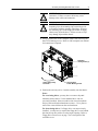
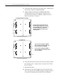
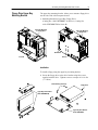
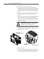
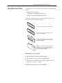
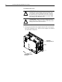
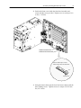
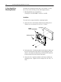
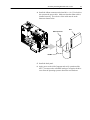
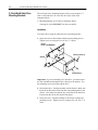
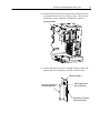
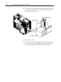
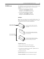
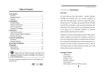
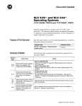
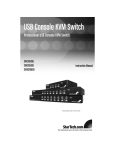
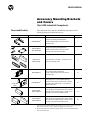
Instructions
Accessory Mounting Brackets
and Covers
(For 6180 Industrial Computers)
Covers and Brackets
Part Number
This instruction sheets provides installation instructions for the
following accessory brackets and covers.
①Catalog
A
Page
6189-LBFDBRKT②
Floppy Drive Lower Bay Mounting Bracket.
Includes 4 drive mounting screws and 4 bracket
mounting screws.
2
6189-UBFDBRKT
6189-UBFDBRKTB
Floppy Drive Upper Bay Mounting Bracket.
Includes 4 drive mounting screws and 1 bracket
mounting screw. Drive cable is included.
5
6189-FDDCVR
6189-FDDCVRB
Floppy Disk Drive Cover Plates. Contains four covers
and 3 cover mounting screws.
7
6189-IB35BRKT②
3.5 Inch Hard Drive Mounting Bracket.
Includes 4 drive mounting screws and 2 bracket
mounting screws.
10
6189-IBSDBRKT②
Solid State Drive or 2.5 Inch Hard Drive Mounting
Bracket. Includes 4 drive mounting screws, 2 bracket
mounting screws, adapter board, 2.5 inch hard drive
cable and IDE cable.
12
6189-FCDBRKT
6189-FCDBRKTB
Cover kit protects CD ROM drive when drive is installed
facing the front of the 6180 computer. Includes 2 cover
mounting screws and 4 drive mounting screws.
15
6189-RCDBRKT
6189-RCDBRKTB
Cover kit protects CD ROM drive when drive is installed
facing the rear of the 6180 computer. Includes 3 cover
mounting screws and 4 drive mounting screws.
15
Includes Drive Cable
B
Description
Number
Includes IDE
Cables
➀ The catalog numbers identify Series B parts by adding “B” to the end of the catalog number.
Make sure the series letter of your computer is appropriate for the brackets.
② When a catalog number for a bracket does not have a letter “B” at the end, that bracket applies to
Series A and Series B units.
2
Accessory Mounting Brackets and Covers
Floppy Drive Lower Bay
Mounting Bracket
The lower bay mounting bracket (Catalog No. 6189-LBFDBRKT)
allows you to mount a floppy drive facing either the front or the back
of the 6180 computer as shown below.
• Mounting Bracket for Lower Bay Floppy Drive
(Catalog No. 6189-LBFDBRKT for Series A and B)
Front Mounting
Rear Mounting
Installation
Note: You can also use these procedures to intstall a front or rear
facing CDROM drive (without mounting bracket). The lower bay
floppy drive mounting bracket and CDROM drive use the same sets
of chassis mounting holes.
To install a floppy using the lower bay mounting bracket:
1. Secure the floppy drive to the drive bracket using four screws
supplied with the bracket. Tighten screws to a torque of 6-8 in.
lbs (.7-.9 NSm).
Drive Mounting Screws (4)
Floppy Drive
Drive Bracket
Accessory Mounting Brackets and Covers
!
!
3
ATTENTION: Remove all cables from the side panel
connectors. Failure to remove cables may cause
damage to the cables and connectors.
ATTENTION: If the 6180 Computer is installed with
mounting clips, the mounting clips on the hinge side
will interfere with the opening of the hinge. Remove
the mounting clips on the hinge side before swinging
chassis away from the bezel. Failure to remove clips
may damage clips and the chassis.
2. Swing open the back of the computer chassis after removing the
three bezel latching screws. Refer to 6180 computer user manual
for instructions if required.
Front Bezel
Latching Screws (3)
Chassis Swings Away
From Bezel
Cover Knockout
for Rear Mounting of Drive
3. Position the accessory drive / bracket assembly into the chassis.
Notes:
For rear facing drives, you may have to remove the panel
knockout (shown above) if a rear mounted drive was not
previously installed. Insert screwdriver into slot on knockouts
and pry back and forth on knockout to remove. Use a pliers to
remove the center rib between the two knockouts.
For front facing drives, if a floppy drive was not previously
installed, you may have to replace the floppy drive cover behind
the front access door with a cover having an opening. Refer to
Floppy Drive Front Cover on page 7 for a description of the
available covers.
4
Accessory Mounting Brackets and Covers
4. Connect the cable connectors to the floppy drive. Connectors are
keyed so they cannot be installed backwards.
5. Align the floppy drive/bracket (or CDROM) and chassis
mounting holes and secure the with the 4 mounting screws
provided with the bracket (or CDROM). Tighten screws to a
torque of 6-8 in. lbs (.7-.9 NSm).
For Floppy Drive/Bracket Assembly
Use these chassis holes for both rear and
front mounting of a floppy drive. For front
access mounting, use the rear hole pairs on
the mounting bracket. For rear access
mounting, use the front hole pairs on the
mounting bracket.
Front
6180 Computer (Bottom View)
For CDROM Drive
2
3
For front access mounting of a CDROM
drive, use chassis hole pairs 2 and 5 and
the front hole pairs on the CDROM.
For rear access mounting of a CDROM
drive, use chassis holes 3 and the rear hole
pair on the CDROM.
5
Front
6180 Computer (Bottom View)
6. Swing the chassis back onto the bezel and secure chassis with the
three latching screws. Tighten screws to a torque of 18-22 inch
lbs (2-2.5 NSm).
7. Install the back panel.
8. Apply power to the 6180 Computer and verify operation of the
drive. You may need to edit BIOS settings to recognize the drive
or to allow the operating system to detect the new hardware.
Accessory Mounting Brackets and Covers
Floppy Drive Upper Bay
Mounting Bracket
5
The upper bay mounting bracket allows you to mount a floppy drive
out the side of the 6180 computer chassis.
• Mounting Bracket for Upper Bay Floppy Drive
(Catalog No. 6189-UBFDBRKT for Series A; Catalog No.
6189–UBFDBRKTB for Series B)
Upper Bay Mounting
of Floppy Drive
Upper Bay Mounting
of Floppy Drive
Back Panel
Series B
Series A
Installation
To install a floppy using the upper bay mounting bracket:
1. Secure the floppy drive to the drive bracket using four screws
supplied with the drive. Tighten screws to a torque of 6-8 in. lbs
(.7-.9 NSm).
Drive Mounting Screws (4)
Floppy Drive
Upper Bay Drive Bracket
(6189–UBFDBRKTB)
Upper Bay Drive Bracket
(6189–UBFDBRKT)
6
Accessory Mounting Brackets and Covers
2. Remove the back panel to the 6180 computer.
3. A shorter drive cable is provided with the mounting kit for
mounting in the upper bay. Connect the cable to the floppy drive
connector on the processor board (refer to the Processor Board
user manual if necessary) and the connector on the back of the
drive.
4. Position the accessory drive / bracket assembly into the chassis.
The edge of the bracket fits under the tab at the front of the
chassis.
Note: You may have to remove the side panel knockout (shown
below) if a side mounted drive was not previously installed.
Insert screwdriver into slot on knockouts and pry back and forth
on knockout to remove. Use a pliers to remove the center rib
between the two knockouts.
!
ATTENTION: If knockout is removed, carefully
remove any burrs or sharp edges. Failure to remove
sharp edges could result in personal injury.
5. Align the bracket and chassis mounting hole and secure the drive
/ bracket assembly with a mounting screw. Tighten screw to a
torque of 6-8 in. lbs (.7-.9 NSm).
Cover Knockout
for Upper Bay Mounting of Drive
Bracket with Drive
in Upper Bay
Bracket Mounting Screw
6. Install the back panel.
7. Apply power to the 6180 Computer and verify operation of the
drive. You may need to edit BIOS settings to recognize the drive
or to allow the operating system to detect the new hardware.
Accessory Mounting Brackets and Covers
Floppy Drive Cover Plates
7
The floppy drive cover plates provide protection for installed floppy
drives.
• Floppy Drive Cover Plates
(Catalog No. 6189-FDDCVR for Series A;
Catalog No. 6189-FDDCVRB for Series B)
There are four floppy drive cover plates (2 front covers, 2 rear
covers). Use the cover plates as follows:
Use this rear cover when a floppy drive is rear mounted.
Use this rear cover when front mounting a floppy drive or
if a floppy drive is not installed.
Use this front cover when Floppy Drive is front mounted.
The cover mounts under the front access door to protect
the front of the floppy drive.
Use this front cover when Floppy Drive is rear mounted or
not installed. The cover mounts under the front access
door to protect the rear of the floppy drive or to prevent
access to the inside of the computer.
To install the rear cover plate:
1. Remove the back panel to the 6180 computer.
2. Position the cover on the inside of the back panel.
3. Secure the cover with the screw provided. Tighten screw to a
torque of 6-8 in. lbs (.7-.9 NSm).
4. Install the back panel on the 6180 computer.
8
Accessory Mounting Brackets and Covers
To install a front cover:
!
!
ATTENTION: If the 6180 Computer is installed with
mounting clips, the mounting clips on the hinge side
will interfere with the opening of the hinge. Remove
the mounting clips on the hinge side before swinging
chassis away from the bezel. Failure to remove clips
may damage clips and the chassis.
ATTENTION: Remove all cables from the the side
panel connectors. Failure to remove cables may cause
damage to the cables and connectors.
1. Swing open the back of the computer chassis after removing the
three bezel latching screws. Refer to 6180 computer user manual
for instructions if required.
Front Bezel
Latching Screws (3)
Chassis Swings Away
From Bezel
Accessory Mounting Brackets and Covers
9
2. Position the front cover inside the front bezel assembly and
secure with the screw provided. Tighten screw to a torque of 6-8
in. lbs (.7-.9 NSm).
Install Screw to Secure Cover
Install Front Cover from the Inside
Make sure bottom edge of cover fits
between edge of chassis and the two tabs.
Tab
Edge of Chassis
3. Swing the chassis back onto the bezel and secure chassis with the
three latching screws. Tighten screws to a torque of 18-22 inch
lbs (2-2.5 NSm).
10
Accessory Mounting Brackets and Covers
3.5 Inch Hard Drive
Mounting Bracket
The hard drive mounting brackets allow you to mount a 3.5 inch
drive in one of the drive bays of the 6180 computer chassis.
• Mounting Bracket for 3.5 Inch Drives
(Catalog No. 6189-IB35BRKT for Series A and B)
Installation
To install a drive using the hard drive mounting bracket:
1. Secure the drive to the bracket with the four mounting screws.
Tighten screw to a torque of 6-8 in. lbs (.7-.9 NSm).
Bracket
Part No. 6189-IB35BRKT
3.5 Inch Drive
Mounting Screws (4)
2. Position the drive / bracket assembly into the chassis. Make sure
the hook on the bracket slide into the corresponding hole in the
chassis. Also make sure that the key on the end of the bracket is
inserted into the slot on the chassis front panel.
3. Secure the drive / bracket assembly to the chassis with the two
mounting screws. Tighten screw to a torque of 6-8 in. lbs (.7-.9
NSm).
Accessory Mounting Brackets and Covers
11
4. Install the ribbon connector on the hard drive. On 3.5 inch drives
also connect the power cable. Make sure that the ribbon cable is
installed correctly. The red wire of the cable must be at the
bottom as shown below:
Drive
Ribbon Connector
Red Wire
5. Install the back panel.
6. Apply power to the 6180 Computer and verify operation of the
drive. You may need to edit BIOS settings to recognize the drive
or to allow the operating system to detect the new hardware.
12
Accessory Mounting Brackets and Covers
2.5 Inch/Solid State Drive
Mounting Brackets
The solid state drive mounting brackets allow you to mount a 2.5
inch or solid state drive in one of the drive bays of the 6180
computer chassis.
• Mounting Bracket for 2.5 Inch or Solid State Drives
(Catalog No. 6189-IBSDBRKT for Series A and B)
Installation
To install a drive using the solid state drive mounting bracket:
1. Secure the drive to the bracket with the four mounting screws.
Tighten screw to a torque of 6-8 in. lbs (.7-.9 NSm).
Bracket
Part No. 6189-IBSDBRKT
Mounting Screws (4)
Standoff
Solid State Drive
Important: If you are installing a 2.5 inch drive, you must remove
the four standoffs and mount the drive directly to the bracket. Use
the mounting screws provided with the drive.
2. Position the drive / bracket assembly into the chassis. Make sure
the hook on the bracket slides into the corresponding hole in the
chassis. Also make sure that the key on the end of the bracket is
inserted into the slot on the chassis front panel.
3. Secure the drive / bracket assembly to the chassis with the two
mounting screws. Tighten screw to a torque of 6-8 in. lbs (.7-.9
NSm).
Accessory Mounting Brackets and Covers
13
4. Install the IDE converter board (provided with bracket) on the
two standoffs on the left side of the drive bays. The converter
board snaps on to the standoffs, no hardware is required.
IDE Converter Board
5. Connect the shorter processor board IDE cable (provided with
bracket) and power connector to the IDE converter board.
IDE Converter Board
Drive Cable (provided with
bracket) Connects Here
Power Supply Cable for
Drive Connects Here.
IDE Cable From Processor
Board Connects Here
14
Accessory Mounting Brackets and Covers
6. Connect the drive ribbon cable (provided with bracket) to the IDE
converter board and the drive. The red wire of the cable must be
at the bottom as shown below:
IDE Converter Board
Ribbon Connector
Drive
Red Wire
7. Install the back panel.
8. Apply power to the 6180 Computer and verify operation of the
drive. You may need to edit BIOS settings to recognize the drive
or to allow the operating system to detect the new hardware.
Accessory Mounting Brackets and Covers
CD ROM Covers
15
The CD ROM covers provide protection for the part of the drive that
extends from the 6180 computer chassis. Two cover kits are
available:
• Cover Kit for Front Mounting of CD ROM
(Catalog No. 6189-FCDBRKT for Series A;
Catalog No. 6189-FCDBRKTB for Series B)
• Cover Kit for Rear Mounting of CD ROM
(Catalog No. 6189-RCDBRKT for Series A;
Catalog No. 6189-RCDBRKTB for Series B)
Installation
Note: There are two bags of screws provided with the bracket. Use
the three flush head mounting screws to mount the covers. Use the
remaining four screws to secure the CD ROM drive.
Catalog No. 6189-FCDBRKT
Catalog No. 6189-FCDBRKTB
Use this rear cover when a CD Drive is front mounted.
The cover mounts on the back panel to protect the rear
of the CD drive.
Use this front cover when a CD Drive is rear mounted.
The cover mounts under the front access door to protect
the rear of the CD drive.
Catalog No. 6189-RCDBRKT
Catalog No. 6189-RCDBRKTB
Use this rear cover when a CD Drive is rear mounted.
The cover mounts to the back panel to protect the front of
the CD drive while allowing access to the drive.
To install a rear cover:
1. Remove the back panel to the 6180 computer.
2. Position the cover on the inside of the back panel.
3. Secure the cover with the screw provided. Tighten screw to a
torque of 6-8 in. lbs (.7-.9 NSm).
4. Install the back panel.
To install a front cover, refer to the instructions on page 8.
To install a CD ROM, refer to the instructions on page 4.
16
Accessory Mounting Brackets and Covers
Allen-Bradley, a Rockwell Automation Business, has been helping its customers improve
productivity and quality for more than 90 years. We design, manufacture and support a broad
range of automation products worldwide. They include logic processors, power and motion
control devices, operator interfaces, sensors and a variety of software. Rockwell is one of the
world’s leading technology companies.
Worldwide representation.
Argentina • Australia • Austria • Bahrain • Belgium • Brazil • Bulgaria • Canada • Chile • China, PRC • Colombia • Costa Rica • Croatia • Cyprus • Czech Republic • Denmark •
Ecuador • Egypt • El Salvador • Finland • France • Germany • Greece • Guatemala • Honduras • Hong Kong • Hungary • Iceland • India • Indonesia • Ireland • Israel • Italy •
Jamaica • Japan • Jordan • Korea • Kuwait • Lebanon • Malaysia • Mexico • Netherlands • New Zealand • Norway • Pakistan • Peru • Philippines • Poland • Portugal • Puerto
Rico • Qatar • Romania • Russia–CIS • Saudi Arabia • Singapore • Slovakia • Slovenia • South Africa, Republic • Spain • Sweden • Switzerland • Taiwan • Thailand • Turkey •
United Arab Emirates • United Kingdom • United States • Uruguay • Venezuela • Yugoslavia
Allen-Bradley Headquarters, 1201 South Second Street, Milwaukee, WI 53204 USA, Tel: (1) 414 382-2000 Fax: (1) 414 382-4444
41061-042-01(D)
Copyright 1998 Allen-Bradley Company, Inc. Printed in USA