1
Operation Manual
(printable Help file)
Table Of Contents
ii
Table Of Contents
1.
Auto Mixer Combiner .................................................................................................................................................. 1
2.
Source Selections ........................................................................................................................................................ 1
3.
Level .............................................................................................................................................................................. 4
4.
Level Inc/Dec ................................................................................................................................................................ 5
5.
Invert ............................................................................................................................................................................. 5
6.
Mute Button .................................................................................................................................................................. 6
7.
Preset Button ............................................................................................................................................................... 6
8.
Remote Preset Button ................................................................................................................................................. 6
9.
Logic Gates .................................................................................................................................................................. 6
10. Logic Delay................................................................................................................................................................... 8
11. Command String .......................................................................................................................................................... 9
12. Volume 8 ..................................................................................................................................................................... 10
13. Select 8 ........................................................................................................................................................................11
14. Volume/Select 8 ......................................................................................................................................................... 12
15. RED-1 .......................................................................................................................................................................... 13
16. Voltage Control Box................................................................................................................................................... 15
17. VCB Calibration ......................................................................................................................................................... 16
18. Logic Box ................................................................................................................................................................... 17
19. Control Labels ............................................................................................................................................................ 19
20. Features ...................................................................................................................................................................... 20
21. Architect's & Engineer's Specifications .................................................................................................................. 20
22. Warranty ..................................................................................................................................................................... 23
23. Documentation ........................................................................................................................................................... 24
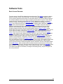
24. Software Tools ........................................................................................................................................................... 25
25. Basic Screen Elements ............................................................................................................................................. 25
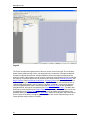
26. Layout ......................................................................................................................................................................... 26
iii
Nexia Manual LTR
27. Bird's Eye View .......................................................................................................................................................... 27
28. Processing Library .................................................................................................................................................... 27
29. Object Toolbar ............................................................................................................................................................ 28
30. Format Toolbar ........................................................................................................................................................... 29
31. Font ............................................................................................................................................................................. 29
32. Size .............................................................................................................................................................................. 29
33. Bold ............................................................................................................................................................................. 30
34. Italic ............................................................................................................................................................................. 30
35. Align Left .................................................................................................................................................................... 30
36. Center ......................................................................................................................................................................... 30
37. Align Right .................................................................................................................................................................. 30
38. Back Color .................................................................................................................................................................. 30
39. Text Color ................................................................................................................................................................... 31
40. Fore Color ................................................................................................................................................................... 31
41. Hilite Color .................................................................................................................................................................. 31
42. Pen Width ................................................................................................................................................................... 31
43. Hatch Style ................................................................................................................................................................. 31
44. Layout Toolbar ........................................................................................................................................................... 32
45. Property Sheet ........................................................................................................................................................... 32
46. Layout Property Sheet .............................................................................................................................................. 32
47. Line Property Sheet ................................................................................................................................................... 33
48. Object Property Sheet ............................................................................................................................................... 34
49. Object Inspector ........................................................................................................................................................ 35
50. Layers Sheet .............................................................................................................................................................. 35
51. Toggle Grid ................................................................................................................................................................. 36
52. Toggle Ruler ............................................................................................................................................................... 36
iv
Table Of Contents
53. Bird's Eye View .......................................................................................................................................................... 36
54. Zoom In ....................................................................................................................................................................... 36
55. Zoom Out .................................................................................................................................................................... 36
56. Zoom 1:1 ..................................................................................................................................................................... 37
57. Zoom Level ................................................................................................................................................................. 37
58. Pack Objects .............................................................................................................................................................. 37
59. Align Edges ................................................................................................................................................................ 37
60. Center In View ............................................................................................................................................................ 38
61. Space .......................................................................................................................................................................... 38
62. Make Same Size ......................................................................................................................................................... 38
63. To Front Or Back ........................................................................................................................................................ 38
64. Network Toolbar ......................................................................................................................................................... 39
65. Connect ...................................................................................................................................................................... 39
66. Disconnect ................................................................................................................................................................. 39
67. Connect To System ................................................................................................................................................... 39
68. Disconnect From System .......................................................................................................................................... 40
69. Send Configuration ................................................................................................................................................... 40
70. Sync Data.................................................................................................................................................................... 40
71. Start Audio .................................................................................................................................................................. 40
72. Stop Audio .................................................................................................................................................................. 41
73. Device Maintenance .................................................................................................................................................. 41
74. Device Maintenance Dialog Box............................................................................................................................... 41
75. Standard Toolbar ....................................................................................................................................................... 45
76. New ............................................................................................................................................................................. 45
77. Open ............................................................................................................................................................................ 45
78. Save ............................................................................................................................................................................ 45
v
Nexia Manual LTR
79. Compile ....................................................................................................................................................................... 46
80. Cut ............................................................................................................................................................................... 46
81. Copy ............................................................................................................................................................................ 46
82. Paste ........................................................................................................................................................................... 46
83. Undo ............................................................................................................................................................................ 46
84. Redo ............................................................................................................................................................................ 46
85. Print ............................................................................................................................................................................. 46
86. Help ............................................................................................................................................................................. 46
87. Main Menus ................................................................................................................................................................ 47
88. File Menu .................................................................................................................................................................... 47
89. New ............................................................................................................................................................................. 47
90. Open ............................................................................................................................................................................ 48
91. Export ......................................................................................................................................................................... 48
92. Close ........................................................................................................................................................................... 48
93. Save ............................................................................................................................................................................ 48
94. Save As ....................................................................................................................................................................... 48
95. Compile ....................................................................................................................................................................... 48
96. Network ....................................................................................................................................................................... 48
97. Print ............................................................................................................................................................................. 49
98. Print Preview .............................................................................................................................................................. 49
99. Print Setup .................................................................................................................................................................. 49
100. Recent File .................................................................................................................................................................. 49
101. Exit .............................................................................................................................................................................. 49
102. Edit Menu .................................................................................................................................................................... 50
103. Undo ............................................................................................................................................................................ 50
104. Redo ............................................................................................................................................................................ 50
vi
Table Of Contents
105. Cut ............................................................................................................................................................................... 50
106. Copy ............................................................................................................................................................................ 50
107. Paste ........................................................................................................................................................................... 51
108. Copy DSP Data ........................................................................................................................................................... 51
109. Paste DSP Data .......................................................................................................................................................... 51
110. Duplicate ..................................................................................................................................................................... 51
111. Select All ..................................................................................................................................................................... 51
112. Delete .......................................................................................................................................................................... 52
113. Control Dialog ............................................................................................................................................................ 52
114. View Menu .................................................................................................................................................................. 52
115. Processing Library Menu .......................................................................................................................................... 52
116. Presets Menu.............................................................................................................................................................. 53
117. Create/Edit/Recall ...................................................................................................................................................... 53
118. Recall .......................................................................................................................................................................... 55
119. Custom Blocks Menu ................................................................................................................................................ 55
120. Create Custom Block Document .............................................................................................................................. 56
121. Merge Into Custom Block ......................................................................................................................................... 56
122. Split Into Component Blocks .................................................................................................................................... 57
123. Tools Menu ................................................................................................................................................................. 58
124. Passwords .................................................................................................................................................................. 58
125. Equipment Table ........................................................................................................................................................ 59
126. Object Inspector ........................................................................................................................................................ 59
127. Layout Compile Results ............................................................................................................................................ 60
128. Signal Path Identifier ................................................................................................................................................. 61
129. Options ....................................................................................................................................................................... 61
130. General Options ......................................................................................................................................................... 61
vii
Nexia Manual LTR
131. Display Options ......................................................................................................................................................... 62
132. Compile Options ........................................................................................................................................................ 63
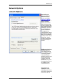
133. Network Options ........................................................................................................................................................ 65
134. Network Options ........................................................................................................................................................ 65
135. Layout Menu ............................................................................................................................................................... 67
136. Align Objects .............................................................................................................................................................. 68
137. Order ........................................................................................................................................................................... 68
138. Object Sheet ............................................................................................................................................................... 68
139. Grid Settings .............................................................................................................................................................. 69
140. Window Menu ............................................................................................................................................................. 69
141. Help Menu ................................................................................................................................................................... 69
142. Status Bar ................................................................................................................................................................... 70
143. Keyboard Shortcuts................................................................................................................................................... 70
144. Component Objects ................................................................................................................................................... 73
145. CS Hardware .............................................................................................................................................................. 73
146. CS Input 10 Channel .................................................................................................................................................. 75
147. CS Output 6 Channel ................................................................................................................................................. 75
148. Conference System ................................................................................................................................................... 76
149. PM Hardware .............................................................................................................................................................. 76
150. PM Input 4 Channel ................................................................................................................................................... 78
151. PM Input (Stereo) 12 Channel ................................................................................................................................... 79
152. PM Output (Stereo) 6 Channel .................................................................................................................................. 80
153. Presentation Mixer ..................................................................................................................................................... 81
154. SP Hardware ............................................................................................................................................................... 82
155. SP Input 4 Channel .................................................................................................................................................... 84
156. SP Output 8 Channel ................................................................................................................................................. 84
viii
Table Of Contents
157. Speaker Processor .................................................................................................................................................... 85
158. VC Hardware .............................................................................................................................................................. 85
159. VC - AEC Input 8 Channel ......................................................................................................................................... 88
160. VC - AEC Ref 8 Channel ............................................................................................................................................ 89
161. VC - Pre-AEC 8 Channel ............................................................................................................................................ 90
162. VC - Input 2 Channel .................................................................................................................................................. 91
163. VC - Output 4 Channel ............................................................................................................................................... 91
164. VC - Codec In 1 Channel ........................................................................................................................................... 92
165. VC - Codec Out 1 Channel ........................................................................................................................................ 92
166. Videoconference System .......................................................................................................................................... 93
167. TC Hardware............................................................................................................................................................... 94
168. TC - AEC Input 8 Channel ......................................................................................................................................... 96
169. TC - AEC Ref 8 Channel ............................................................................................................................................ 97
170. TC - Pre-AEC 8 Channel ............................................................................................................................................ 98
171. TC - Input 2 Channel .................................................................................................................................................. 99
172. TC - Output 4 Channel ............................................................................................................................................. 100
173. Telephone Interface ................................................................................................................................................. 100
174. Teleconference System ........................................................................................................................................... 104
175. NexLink ..................................................................................................................................................................... 105
176. Mixers ....................................................................................................................................................................... 106
177. Auto Mixers .............................................................................................................................................................. 106
178. Standard Mixers ....................................................................................................................................................... 108
179. Matrix Mixers ............................................................................................................................................................ 108
180. Room Combiners ..................................................................................................................................................... 108
181. Equalizers ..................................................................................................................................................................110
182. Parametric Equalizer ................................................................................................................................................110
ix
Nexia Manual LTR
183. Graphic Equalizer .....................................................................................................................................................111
184. Feedback Suppressor ..............................................................................................................................................112
185. Filters .........................................................................................................................................................................112
186. High Pass Filter .........................................................................................................................................................113
187. Low Pass Filter .........................................................................................................................................................114
188. High Shelf Filter ........................................................................................................................................................114
189. Low Shelf Filter .........................................................................................................................................................115
190. All-Pass Filter ............................................................................................................................................................115
191. Crossovers ................................................................................................................................................................116
192. 2-Way Crossover.......................................................................................................................................................116
193. 3-Way Crossover.......................................................................................................................................................117
194. 4-Way Crossover.......................................................................................................................................................118
195. Dynamics ...................................................................................................................................................................118
196. Leveler .......................................................................................................................................................................119
197. Comp/Limiter .............................................................................................................................................................119
198. Ducker ....................................................................................................................................................................... 120
199. Noise Gate ................................................................................................................................................................ 120
200. Ambient Noise Compensator ................................................................................................................................. 121
201. ANC Setup Procedure ............................................................................................................................................. 121
202. Routers ..................................................................................................................................................................... 123
203. Router ....................................................................................................................................................................... 123
204. Delays ....................................................................................................................................................................... 124
205. Delay ......................................................................................................................................................................... 124
206. Controls .................................................................................................................................................................... 124
207. Level .......................................................................................................................................................................... 126
208. Level Inc/Dec ............................................................................................................................................................ 127
x
Table Of Contents
209. Invert ......................................................................................................................................................................... 127
210. Mute Button .............................................................................................................................................................. 128
211. Preset Button ........................................................................................................................................................... 128
212. Remote Preset Button ............................................................................................................................................. 128
213. Logic Gates .............................................................................................................................................................. 128
214. Logic Delay............................................................................................................................................................... 130
215. Command String ...................................................................................................................................................... 131
216. Volume 8 ................................................................................................................................................................... 132
217. Select 8 ..................................................................................................................................................................... 133
218. Volume/Select 8 ....................................................................................................................................................... 134
219. Voltage Control Box................................................................................................................................................. 135
220. VCB Calibration ....................................................................................................................................................... 136
221. Logic Box ................................................................................................................................................................. 137
222. Control Labels .......................................................................................................................................................... 139
223. Meters ....................................................................................................................................................................... 140
224. Signal Present Meter ............................................................................................................................................... 140
225. Peak Meter ................................................................................................................................................................ 141
226. RMS Meter ................................................................................................................................................................ 141
227. Logic Meter ............................................................................................................................................................... 141
228. Generators ................................................................................................................................................................ 142
229. Tone Generator ........................................................................................................................................................ 142
230. Pink Noise Generator .............................................................................................................................................. 142
231. White Noise Generator ............................................................................................................................................ 143
232. Diagnostics .............................................................................................................................................................. 143
233. Transfer Function .................................................................................................................................................... 143
234. Specialty ................................................................................................................................................................... 144
xi
Nexia Manual LTR
235. Pass-Through ........................................................................................................................................................... 144
236. Split Pass-Through Input ........................................................................................................................................ 145
237. Split Pass-Through Output ..................................................................................................................................... 145
238. System Design ......................................................................................................................................................... 147
239. Placing Component Objects ................................................................................................................................... 147
240. Arranging Component Objects............................................................................................................................... 147
241. Connecting Component Objects ............................................................................................................................ 147
242. Component Object Properties ................................................................................................................................ 148
243. Customizing Component Objects .......................................................................................................................... 149
244. Object and Layout Text ........................................................................................................................................... 150
245. System Compiling Considerations ........................................................................................................................ 150
246. Compile Error Messages ......................................................................................................................................... 151
247. System Network Considerations............................................................................................................................ 155
248. System Connect Considerations ........................................................................................................................... 157
249. System Hardware Connections .............................................................................................................................. 158
250. Proper Gain Structure ............................................................................................................................................. 160
251. Applications ............................................................................................................................................................. 161
252. System Control ........................................................................................................................................................ 162
253. Software User Interface ........................................................................................................................................... 162
254. Remote Control Bus ................................................................................................................................................ 162
255. Remote Control Bus Hub ........................................................................................................................................ 164
256. Third-Party Control .................................................................................................................................................. 165
257. Overview ................................................................................................................................................................... 165
258. RS-232 Control ......................................................................................................................................................... 167
259. Telnet Control ........................................................................................................................................................... 167
260. Command ................................................................................................................................................................. 168
xii
Table Of Contents
261. Device Number ......................................................................................................................................................... 170
262. Attribute .................................................................................................................................................................... 172
263. Input/Output Blocks ................................................................................................................................................ 172
264. Mixer Blocks ............................................................................................................................................................. 178
265. Equalizer Blocks ...................................................................................................................................................... 181
266. Filter Blocks ............................................................................................................................................................. 182
267. Crossover Blocks .................................................................................................................................................... 184
268. Dynamics Blocks ..................................................................................................................................................... 185
269. Router Blocks .......................................................................................................................................................... 186
270. Delay Blocks ............................................................................................................................................................ 187
271. Control Blocks ......................................................................................................................................................... 188
272. Meter Blocks ............................................................................................................................................................ 189
273. Generator Blocks ..................................................................................................................................................... 189
274. Instance ID ................................................................................................................................................................ 189
275. Index ......................................................................................................................................................................... 190
276. Value ......................................................................................................................................................................... 191
277. Responses ................................................................................................................................................................ 192
278. Control Dialog - Overview ....................................................................................................................................... 193
279. Control Dialog - Levels, Presets, & Meters ........................................................................................................... 194
280. HyperTerminal .......................................................................................................................................................... 195
281. IP Address Commands ............................................................................................................................................ 197
282. Get/Set IP Address ................................................................................................................................................... 197
283. Index ......................................................................................................................................................................... 199
xiii
Introduction
Control Dialogs
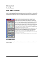
Auto Mixer Combiner
Note: The Auto Mixer Combiner replaces the Mix Minus Combiner in the software and incorporates all of its functionality,
plus some additional features. Files created in previous versions of Nexia that contain a Mix Minus Combiner will still
function normally and the Mix Minus Combiner will still appear in the layout, even though the block will no longer appear in
the Object Toolbar or Processing Library. The user may substitute an Auto Mixer Combiner block anywhere a Mix Minus
Combiner would have been used.
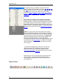
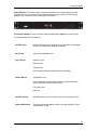
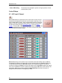
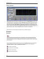
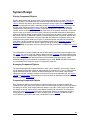
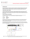
Auto Mixer Combiner blocks enhance the capabilities of Auto Mixers in room
combining, mix-minus, and input expansion applications. Auto Mixer Combiners
combine control data only and, therefore, have no audio outputs. Inputs to an Auto
Mixer Combiner come from the Mix outputs of separate Auto Mixer blocks. Ch /
Combine allows input channels (1, 2, 3, etc.) to be grouped into specific combinations
(A, B, C, etc.). These combinations automatically determine proper routing of control
data for the Auto Mixer blocks. Control data represents NOM (number of open mics),
ATS (adaptive threshold sensing), and last mic hold status information. Auto Mixer
Combiners are used when Auto Mixer outputs are also connected to a separate Matrix
Mixer (to create multiple mix-minus outputs). Auto Mixer Combiners allow large Auto
Mixers to be created from multiple, smaller ones. This is useful when more than 32
inputs are required or when an Auto Mixer must be placed into multiple Nexia units (for
proper DSP allocation or physical location of inputs).
Groups buttons are used to choose a group for viewing and editing two settings: Last
Mic Hold and Open Mic Limits. Last Mic Hold determines whether the last open
microphone across all Auto Mixer inputs assigned to the current group is allowed to
gate off when activity on that channel ceases. Open Mic Limits enables (and
designates) a maximum allowable number of active microphones across all Auto Mixer
inputs assigned to the current group.
Right clicking on Ch / Combine assignments will prompt a menu of additional options.
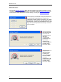
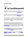
Source Selections
Source Selection blocks are N by 1 routers (where N represents the number of sources) with level control per input and
optional logic input and output connections. Source Selection blocks are useful when remote control of audio source
selection is required.
1
Nexia Manual LTR
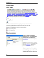
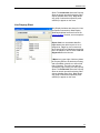
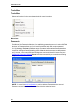
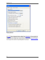
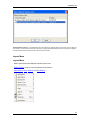
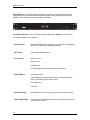
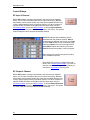
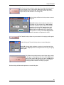
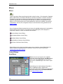
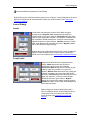
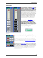
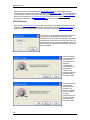
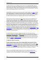
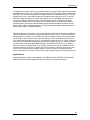
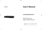
When the user first places a Source Selection
block into an Nexia layout, this prompts an
initialization window.
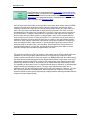
Source Channel Count specifies the number of input
channels (2 to 16) and generally corresponds to the
number of sources from which the user can choose. If the
Source Channel Count is set to Custom, the Chan Count
parameter is used to specify the exact number of
channels desired.
If selected, Enable Logic provides a logic input and output
connection point for each channel.
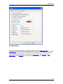
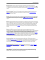
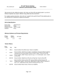
Source Selection is represented in the layout
as a block with a number of audio input
connections (specified by the Source Channel
Count parameter), one audio output
connection, and optionally, a logic input and
output connection point for each channel. If
logic is enabled, a low-to-high logic transition
(i.e., a rising edge) presented to a logic input
connection will cause the Source Selection
block to switch to the corresponding audio
input channel, and the corresponding logic out
connection will be at a logic high. All other
logic outputs will be low.
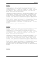
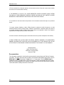
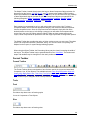
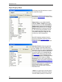
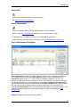
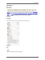
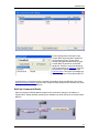
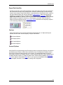
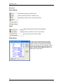
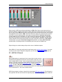
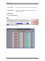
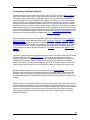
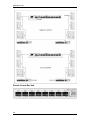
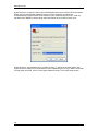
Double clicking on a Source Selection block produces a
control window.
Level (dB) adjusts the level (-100 to 12 dB) of the source
connected to that channel’s input.
Source Selection buttons are used to select the input
source that is routed to the audio output connector of the
Source Selection block. If the user right clicks a source
selection button, this produces a dialog box that allows
customization of the text that is displayed on that button.
This dialog box can be minimized to create user control
surfaces (see Customizing Component Objects).
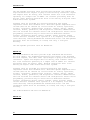
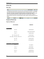
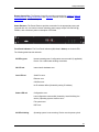
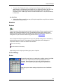
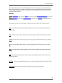
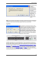
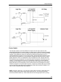
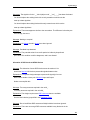
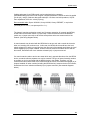
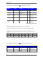
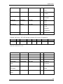
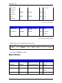
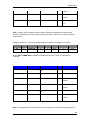
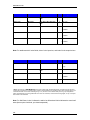
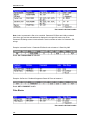
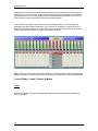
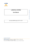
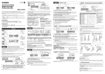
Audio Wiring Diagrams
2
Introduction
Balanced
Inputs
Unbalanced
Inputs
Unbalanced
Stereo to
two
balanced
inputs
Outputs
Balanced
Output
Unbalanced
Output
3
Nexia Manual LTR
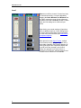
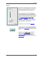
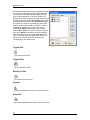
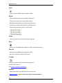
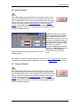
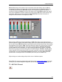
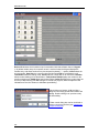
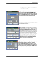
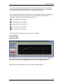
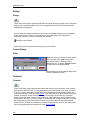
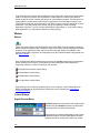
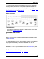
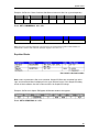
Level
Mute turns on/off the channel. Channel level may
be entered numerically, or may be adjusted by
dragging the fader. Maximum and Minimum can
be used to restrict the range of level adjustment
provided by the fader. Level ID provides a custom
label, when the dialog box is minimized (see
below).
Right-clicking over certain settings will provide a
menu of additional options. Control Dialog Boxes
for Level Control components can be minimized
to create user control surfaces (see Customizing
Component Objects).
When placed from the Object Toolbar, multiple
Level Controls may be 'ganged' together onto a
single fader. Ganged Level Controls display a 'G'
in the upper-right of the Component Object, and
Level ID colors are reversed on the Control
Dialog. Non-ganged Level Controls have a
maximum of 16 channels, whereas ganged Level
Controls have a maximum of 32 channels.
4
Introduction
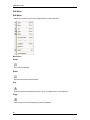
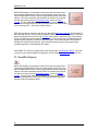
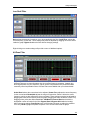
Level Inc/Dec
Level Inc/Dec blocks are identical to Level blocks,
except they also provide control input nodes for
making incremental level changes. Inc/Dec Step
determines the amount of level change to occur
each time the associated control node is
triggered. Control input nodes along the top of the
block are labeled as positive (+) and negative (-).
When triggered by control output nodes on other
components within the layout design, positive
nodes produce a single-step increase in level
("Increment") and negative nodes produce a
single-step decrease in level ("Decrement").
When placed from the Object Toolbar, multiple
Level Inc/Dec Controls may be 'ganged' together
onto a single fader. Also, ramping may be
enabled at this time. When ramping is enabled,
Inc/Dec Rate sets timing (mS) between repetitive
incremental changes (Inc/Dec Steps) which occur
automatically as long as the associated control
node (+ or -) remains triggered.
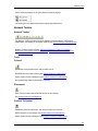
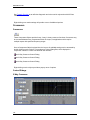
Invert
Invert reverses the polarity of the audio signal (180°). Identifier
provides a custom label, when the dialog box is minimized (see below).
Right-clicking over certain settings will provide a menu of additional
options. Control Dialog Boxes for Invert components can be minimized
to create user control surfaces (see Customizing Component Objects).
When placed from the Object Toolbar, multiple Invert channels may be
'ganged' together onto a single control. Ganged Invert controls display a
'G' in the upper-right of the Component Object, and Identifier colors are
reversed on the Control Dialog. Non-ganged Invert controls have a
maximum of 16 channels, whereas ganged Invert Controls have a
maximum of 32 channels.
5
Nexia Manual LTR
Mute Button
Mute turns on/off the channel. Identifier provides a custom label, when
the dialog box is minimized (see below).
Right-clicking over certain settings will provide a menu of additional
options. Control Dialog Boxes for Mute Button components can be
minimized to create user control surfaces (see Customizing Component
Objects).
When placed from the Object Toolbar, multiple Mute Buttons may be
'ganged' together onto a single button. Ganged Mute Buttons display a
'G' in the upper-right of the Component Object, and Identifier colors are
reversed on the Control Dialog. Non-ganged Mute Buttons have a
maximum of 16 channels, whereas ganged Mute Buttons have a
maximum of 32 channels. Also, Mute Button blocks may be placed with
control input nodes selected.
Preset Button
Right-clicking over a button provides a list of available
Presets which can be assigned to that button. The Preset
Number will appear on the button, and the Preset Name will
appear to the right. Preset Numbers can be replaced with
the word 'Recall' (see General Options). Control Dialog
Boxes for Preset Button components can be minimized to
create user control surfaces (see Customizing Component
Objects).
Remote Preset Button
Remote Preset Buttons are identical to Preset Buttons,
except they have control input nodes on the block. These
control input nodes allow presets to be recalled via control
output nodes on other component blocks. This provides
remote control of preset selection, both from internal
components and external controls. Unlike most other
blocks, multiple control output nodes may be connected to
a single control input node on a Remote Preset Button.
Control Dialog Boxes for Remote Preset Button
components can be minimized to create user control
surfaces (see Customizing Component Objects).
Logic Gates
6
Introduction
Most Logic Gates have no Control Dialog Boxes. They are used only to customize behavior of
other control functions in the system. Logic Gates are connected between the output and input
control nodes of other components in the layout. These components can represent internal or
external control functions.
Examples
Internal: Auto Mixer output nodes; Ducker input/output nodes; Remote Preset Button input nodes.
External: Select 8 output nodes; Volume/Select 8 output nodes; Logic Box input/output nodes.
Logic Gates alter the normal operation of component control outputs in the following ways:
NOT: produces opposite/inverted operation (input HIGH turns output LOW; input LOW turns
output HIGH).
AND: all inputs HIGH causes output to go HIGH (any inputs LOW causes output to go LOW).
NAND: all inputs HIGH causes output to go LOW (any inputs LOW causes output to go HIGH).
OR: any inputs HIGH causes output to go HIGH (all inputs LOW causes output to go LOW).
NOR: any inputs HIGH causes output to go LOW (all inputs LOW causes output to go HIGH).
XOR: any inputs (except all) HIGH causes output to go HIGH (all inputs LOW / HIGH causes
output to go LOW).
Flip Flop: produces toggle/latching operation (input HIGH changes output state, HIGH / LOW).
Logic State: provides manual latching operation only (includes no input node).
7
Nexia Manual LTR
NOTES: NOT and Flip Flop gates have only a single input per output, whereas most other gates
have multiple inputs, up to 8. Flip Flop gates provide a control dialog box, for establishing their
initial output state. Also, unlike most other blocks, multiple control output nodes may be
connected to a single control input node on a Flip Flop gate. Control Dialog boxes for Logic State
gates can be minimized to create user control surfaces (see Customizing Component Objects).
Sample Application
Normally, a Select 8 control output connected to a Ducker control input
provides a momentary operation (ducking occurs only as long as the
Select 8 control is being pressed). However, connecting a Flip Flop
Logic Gate between the Select 8 control output and the Ducker control
input produces a press-on/press-off operation (ducking begins with the
first press of the Select 8 control, and ceases only upon a second press
of the Select 8 control).
Logic Delay
Logic Delays are connected between the output
and input control nodes of other components in the
layout. These other components may represent
internal or external control functions. When a
change (on/off) occurs at the Logic Delay input,
and remains in that condition beyond the
designated delay time, the Logic Delay output will
then produce that same change..
On sets turn on delay. OFF sets turn off delay. The
range for either selection is 0~60,000mS (1
minute). Bypass disables the delay without
changing settings.
Right-clicking over certain settings will provide a
menu of additional options.
8
Introduction
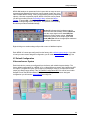
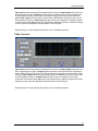
Command String
Command String blocks allow RS-232 control of
external devices via NEXIA's Serial port. Control
input nodes along the top of the block produce
corresponding serial commands, when triggered
by control output nodes on other components
within the design. Commands can also be initiated
using the command button which appears within
the control dialog box. Command ID allows the
command/button to be named. Command String
allows the appropriate character string to be
entered. Update sends the character string to be
stored in NEXIA device memory.
Unlike most other blocks, multiple control output nodes may be connected
to a single control input node on a Command String block. Control Dialog
Boxes for Command String components can be minimized to create user
control surfaces (see Customizing Component Objects).
NOTE: Some command strings may need to output nonprintable characters. The strings
themselves must be printable, so this is done by including three-character sequences in the
command string. The first will be a tilde, the second and third hex digits. To include a carriage
return and line feed pair, for example, in the string, include the text ~0d~0a (either case may be
used). A tilde may only be included by using the sequence ~7E (or ~7e) for the tilde character
itself.
9
Nexia Manual LTR
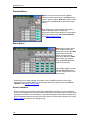
Volume 8
The Volume 8 is an external control device, which allows
adjustment of eight selectable NEXIA volumes. Volumes can
be individual or grouped levels within NEXIA. This includes
Level Control blocks, as well as level adjustments found in
the Control Dialog boxes of other component blocks.
Volume 8 is represented in the layout as a block with no
audio or control connections. All functions are assigned
using the control dialog box. Object Code selects from a list
of blocks found in the layout, and Instance ID is entered
automatically, but both can be found easily using Object ID
Inspector. Control ID selects from a list of available levels
within the chosen block. Volume up/down buttons allow
control of assigned levels directly from the dialog box.
Identifier provides a custom label, when the dialog box is
minimized (see below).
Control Dialog Boxes for Volume 8 components can be
minimized to create user control surfaces (see Customizing
Component Objects).
Volume 8 controls fit most US standard single-gang back-boxes (back-boxes are available
separately from Biamp Systems). Custom Control Labels may be printed for the Volume 8.
Please refer to the 'Installation Guide' (included with controls), or see Remote Control Bus for
more information. External controls must be identified (see Device Maintenance) and associated
with their corresponding component blocks within the layout (see Equipment Table).
10
Introduction
Select 8
The Select 8 is an external control device, which allows
initiation of eight selectable NEXIA actions. Actions can
be individual or grouped functions within NEXIA. This
includes recalling presets, ducking, combining, etc.
Select 8 components have no Control Dialog Boxes.
They are represented in the layout as a block with eight
control output nodes. These control output nodes are
connected to control input nodes on the other component
blocks to be controlled. These other components may
include Remote Preset Buttons, Duckers, Room
Combiners, and Logic Boxes. Muting and room
combining routines can also be achieved using presets.
Logic Boxes can provide logic outputs for controlling
additional equipment, external to NEXIA.
Select 8 behavior can be altered using Logic Gates.
Select 8 controls fit most US standard single-gang backboxes (back-boxes are available separately from Biamp
Systems). Custom Control Labels may be printed for the
Select 8.
Please refer to the 'Installation Guide' (included with
controls), or see Remote Control Bus for more
information. External controls must be identified (see
Device Maintenance) and associated with their
corresponding component blocks within the layout (see
Equipment Table).
11
Nexia Manual LTR
Volume/Select 8
The Volume 8 is an external control
device, which combines the functions of
both Volume 8 and Select 8 controls.
Therefore, the Volume/Select 8 is
represented with a control dialog box
(for volume functions), as well as a
component block with control output
nodes (for select functions).
Control Dialog Boxes for Volume/Select
8 components can be minimized to
create user control surfaces (see
Customizing Component Objects).
Volume/Select 8 controls fit most US
standard 2-gang back-boxes (backboxes are available separately from
Biamp Systems).
Custom Control Labels may be printed
for the Volume/Select 8. Please refer to
the 'Installation Guide' (included with
controls), or see Remote Control Bus for
more information. External controls must
be identified (see Device Maintenance)
12
Introduction
and associated with their corresponding
component blocks within the layout (see
Equipment Table).
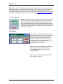
RED-1
Remote Ethernet Device 1 (RED-1) is an external remote control panel that integrates with Nexia
systems via Ethernet, using a single CAT5 cable for control and Power-over-Ethernet (PoE).
RED-1 allows for the selection of up to 32 control items. A control item can be the initiation of a
logic event (such as a preset recall or a source selection), selection of a volume assignment, or
both. Volume assignments may be individual or ganged levels within the layout, including Level
Control blocks, as well as levels within other component blocks (such as Input/Output blocks,
Mixers, Equalizers, etc).
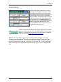
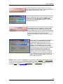
When a RED-1 block is first placed into the
layout, an initialization dialog box appears.
Logic Out specifies the number of logic
connection points (0 to 32) on the RED-1
block. These connection points are typically
wired to Remote Preset or Source Selection
blocks but can also be used as generalpurpose logic inputs.
Device ID is the name given to each RED-1
block and should correspond to the Device
ID of a physical remote panel. No two RED-1
blocks in any layout may have the same
Device ID; however, multiple RED-1 panels
may have the same Device ID. In that case,
the panels’ functions are identical and
governed by the RED-1 block with the
corresponding Device ID.
RED-1 is represented in the layout as a
block with a number of logic connection
points (determined by the Logic Out setting
when the block is created), plus a DF logic
output node, which outputs logic high when
at least one like-named RED-1 unit is
discovered on the network.
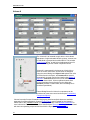
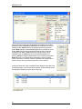
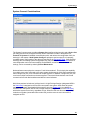
All programmed panel functions are assigned using the control dialog box, which is produced by
double-clicking the RED-1 block.
13
Nexia Manual LTR
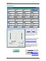
A list displays all defined control items, each with a Channel Number and customizable Control
Label. The New button creates a control item in the list, and the user is prompted to either accept
the default label or enter a new one. Rename allows the user to change the Control Label of the
selected control item. Delete removes the selected control item from the list. Move Up and Move
Down modify the order of the control items in the list, giving the user the ability to control the
display order of the control items on the RED-1 panel.
Each control item may have a Level Control assignment, a Logic Control assignment, or both.
Level Control
Object Code selects from a list of blocks found in the layout, and the Instance ID is entered
automatically, if known. Control ID selects from a list of available levels within the chosen block.
Logic Control
Logic Index specifies which logic connection point, if any, on the RED-1 block will be triggered
when that control item is selected.
Once the RED-1 block has been programmed with control items, the Select and Up/Down Arrow
buttons at the bottom of the control dialog box may be used to mimic how the control will function
from the physical panel.
Control dialog boxes for RED-1 devices may be minimized to create user control surfaces (see
Customizing Component Objects).
14
Introduction
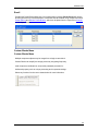
Voltage Control Box
The Voltage Control Box (VCB) is an external control
device, which provides four analog potentiometer
inputs and four logic inputs/outputs. When a VCB is
placed, an Initialization Properties dialog box appears
for assigning the quantities of logic inputs/outputs (4
total). Although the quantity of logic connections on a
Voltage Control Box (4) is different from those on a
Logic Box (20), their operation and behavior are
identical. (See Logic Box for further explanation of
logic inputs/outputs).
Once a VCB block has been placed, double-clicking it will produce a dialog for assigning Analog
(potentiometer) controls. A single VCB allows potentiometer adjustment of up to four selectable
Nexia levels. Levels can be individual or ganged levels within Nexia. This includes Level Control
blocks, as well as levels within other component blocks (such as Inputs & Outputs, Mixers,
Equalizers, etc.). Object Code selects from a list of blocks found in the layout, and Instance ID is
entered automatically, but both can be found easily using Object ID Inspector. Control ID selects
from a list of available levels within the chosen block. Identifier provides a custom label for the
assigned control.
External controls must be identified (see Device Maintenance) and associated with their
corresponding component blocks within the layout (see Equipment Table). The VCB will assume
a full range of 0~5 Volts returning from connected potentiometers, unless the VCB Calibration
procedure is followed (see Device Maintenance). Please refer to the 'Installation Guide'
(included with controls), or see Remote Control Bus for more information.
15
Nexia Manual LTR
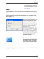
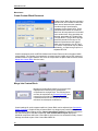
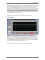
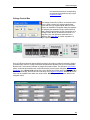
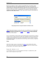
VCB Calibration
Once a VCB (Voltage Control Box) block has been assigned in a Nexia configuration, and the
VCB device (with potentiometers attached) is connected to the Nexia Remote Control Bus, the
potentiometers can be calibrated for accurate tracking of levels (see Device Maintenance).
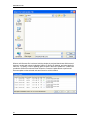
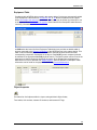
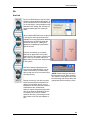
The first screen encountered in this process allows for
the selection of the potentiometer Channel to be
calibrated. Channel numbers correspond to the Analog
potentiometer connections on the VCB itself. Only one
potentiometer Channel can be calibrated at a time, and
only Channels with potentiometers actually connected
will be available.
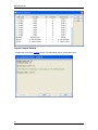
Once the Channel
has been selected,
this screen will
prompt the user to
adjust the
corresponding
potentiometer (on
the selected
Channel) to its
maximum (highest)
physical setting,
then select "Next".
Once the maximum
potentiometer
setting has been
recorded, this
screen will prompt
the user to adjust
the same
potentiometer to its
minimum (lowest)
physical setting,
then select "Next".
16
Introduction
When maximum and
minimum
potentiometer
settings have both
been recorded, this
screen will indicate
the voltage
measurements and
prompt the user to
either accept these
values or recalibrate. "Finish"
will return to the
Channel selection
screen.
NOTE: The entire range of level adjustment assigned to a potentiometer will be controlled by the
voltage range measured during calibration. If the potentiometer is not calibrated, or is calibrated
incorrectly, accurate control of the intended range of levels may not be achieved.
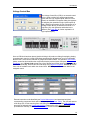
Logic Box
The Logic Box is an external control device, which
provides twenty logic input/output connections. When
a Logic Box is placed, an Initialization Properties
dialog box appears for assigning the quantities of
logic inputs/outputs (20 total). Logic inputs allow
external switches to initiate NEXIA actions. Actions
can be individual or grouped functions within NEXIA.
This includes recalling presets, ducking, combining,
etc. Logic outputs can be used to control additional
equipment, external to NEXIA.
Logic Box components have no Control Dialog Boxes. They are represented in the layout as a
block with a total of twenty control input/output nodes. Logic Inputs (on the box) are represented
as control output nodes (on the block). These control output nodes may be connected to control
input nodes on other components, such as Remote Preset Buttons, Room Combiners, Duckers,
Mute Buttons, and Level Inc/Dec controls. Logic Outputs (on the box) are represented as control
input nodes (on the block). These control input nodes may be connected to control output nodes
on other components, such as Auto Mixers, Duckers, and Select 8. Unlike other components,
Logic Box output nodes may be connected to input nodes on the same Logic Box block, allowing
Logic Inputs (external switches) to control Logic Outputs (external equipment).
17
Nexia Manual LTR
Logic Box behavior can be altered using Logic Gates. Please refer to the
'Installation Guide' (included with controls), or see Remote Control Bus for
more information. External controls must be identified (see Device
Maintenance) and associated with their corresponding component blocks
within the layout (see Equipment Table).
Up to 20 logic inputs are availble on the Logic Box. Logic inputs allow remote control of NEXIA
via external circuits such as switches, relays, and logic outputs from other devices. When
nothing is connected to a logic input, an internal pull-up resistor keeps it at a 'high' state (+5.0
VDC). The logic input is activated when its input goes 'low' (less than +0.8 VDC), and is deactivated when its input goes 'high' (greater than +2.0 VDC). A logic input can be controlled in
one of three ways: 1) Using an 'open-collector' or 'open-drain' logic output from an external
device to short the logic input to ground. 2) Using a switch, relay, or other contact-closure to
short the logic input to ground. 3) Using an active 5V TTL output driver circuit (such as from a
third-party controller) to actively drive the logic input to a 'high' or 'low' state. Multiple contactclosures or 'open-collector'/'open-drain' logic outputs may be wired in parallel to a single logic
input (see diagram below). Open-collector or open-drain logic outputs and contact-closures
should be rated for at least 5 Volts / 1mA operation. Active output driver circuits should not
exceed a signal range of 0~5 Volts DC, and should have a minimum pulse width of 10 milliseconds. The logic input impedance is approximately 10k ohms.
The Logic Box provides up to 20 logic outputs. Logic outputs can be used to control relays and
indicators or to drive logic inputs of other devices. The Logic Box logic outputs are 'open
collector' with an internal pull-up. Each logic output is an NPN transistor with the collector being
the output and the emitter being ground (see diagram below). When a logic output is turned on,
the transistor provides a path for DC current to flow, lowering the output voltage to below 0.8V.
When a logic output is turned off, the internal pull-up resistor raises the output voltage to near
5V, depending on the output current. To activate external relays or indicators, an external power
supply must be used (see diagram below). The logic output transistors are rated up to a
maximum of 40 VDC and 500 mA per output (24 volt relay coils maximum). However, +12 Volts
DC is sufficient power for most applications. When using the logic outputs to control relays,
protection diodes must be used to suppress high voltage transients that are generated when the
relays turn off (see diagram below).
18
Introduction
Control Labels
The Volume 8, Select 8, and Volume/Select 8 controls all come with a sheet of clear,
adhesive-backed labels, for custom printing on a laser printer. A Word document is available
on the NEXIA software CD and on the Biamp web site (www.biamp.com), as a label printing
template. These labels are meant to be printed using desk-top laser printers only. It is
recommended that the printer be set for 'label' printing, and the label sheet should be 'shortedge' feed from the 'bypass' tray. A test printing of a single label should be done, to assure
proper alignment of text. To compensate for any mis-alignment of text, margins within the
Word document may be adjusted. Care should be taken in placement of the labels onto the
controls. To avoid finger-prints, the use of a knife-blade or tweezers is recommended for
handling. Severe bending or curling of the label may cause loss of some toner (text). When
placing the label on the control panel, use the vertical column of LED indicators as a visual
reference of alignment. Once the label is in place, a second (un-printed) label may be placed
over the first label, to provide protection against wear. Each sheet contains 25 labels, so in
case of errors, additional labels may be printed.
NOTE: Originally, labels were 1.35" wide and used the Word document (V8S8 Labels.doc).
However, newer control panels require labels which are only 1.25" wide and use Word
document (V8S8 B Labels.doc). Check label width and use the appropriate file for printing.
19
Nexia Manual LTR
In the Word document, select Show Gridlines from the Table menu. Each large cell represents
a label. The first four columns are 'left-justified' to create labels for Volume 8 and Select 8
panels, as well as for the 'Volume' (left) section of Volume/Select 8 panels. The last column is
'right-justified' to create labels for the 'Select' (right) section of Volume/Select 8 panels. Leftclick inside any large cell, and begin typing. Use 'Enter' to begin a new line, and again to leave
a blank line. To avoid printing errors, do not change line-spacing or other formatting
parameters. However, if you do not have the default font (Helvetica), or if you wish to change
label appearance, you may select a different font before typing.
Features
The NEXIA family of digital signal processors (DSP) is designed with application specific inputs
and outputs (I/O), but with much more power than comparable analog products. Intuitive dragand-drop software allows for easy configuration and maximum flexibility. Setup and control is
achieved utilizing Ethernet ports. NexLink ports allow up to four NEXIA units (any models) to be
used together in the same system, providing totally different combinations of functionality.
NEXIA CS has 10 mic/line inputs and 6 independent mix outputs, and is intended for a variety of
conferencing applications such as boardrooms, courtrooms, and council chambers.
NEXIA PM has 4 mic/line inputs, 6 stereo line inputs, and 6 line outputs, and is intended for multimedia presentation applications requiring both microphone and program content.
NEXIA SP has 4 line inputs and 8 independent mix outputs, and is intended for speaker
processing applications requiring line inputs feeding a larger number of discrete outputs.
NEXIA VC has 8 wide-band AEC mic/line inputs, 2 standard mic/line inputs, 4 mic/line outputs,
and a codec interface, and is intended for a variety of videoconferencing applications such as
boardrooms, courtrooms, and council chambers.
NEXIA TC has 8 wide-band AEC mic/line inputs, 2 standard mic/line inputs, 4 mic/line outputs,
and a telephone interface, and is intended for a variety of teleconferencing applications such as
boardrooms, courtrooms, and council chambers.
NEXIA software includes a broad selection of audio components, routing options, and signal
processing. The internal system design is completely user definable via PC software, and can be
controlled via dedicated software screens, RS-232 control systems, and/or a variety of optional
remote control devices.
Architect's & Engineer's Specifications
20
Introduction
NEXIA® CS
The DSP conference system shall provide ten balanced mic/line inputs
and six balanced mic/line outputs on plug-in barrier-strip connectors.
Inputs and outputs shall be analog, with internal 24-bit A/D & D/A
converters operating at a sample rate of 48kHz. All internal processing
shall be digital (DSP). NexLink connections shall allow sharing of
digital audio within multi-unit systems.
Software shall be provided for creating/connecting DSP system
components within each hardware unit. Available system components shall
include (but not be limited to) various forms of: mixers, equalizers,
filters, crossovers, dynamics/gain controls, routers, delays, remote
controls, meters, generators, and diagnostics. Ethernet communications
shall be utilized for software control and configuration. After initial
programming, processors may be controlled via dedicated software
screens, third-party RS-232 control systems, and/or optional remote
control devices. Software shall operate on a PC computer, with network
card installed, running Windows® XP Professional/Vista. The DSP
conference system shall be CE marked, UL listed, and carry a five-year
warranty.
The DSP conference system shall be NEXIA® CS.
NEXIA® PM
The DSP presentation mixer shall provide four balanced mic/line inputs
and three balanced stereo line outputs on plug-in barrier-strip
connectors, plus six unbalanced stereo line inputs on RCA connectors.
Inputs and outputs shall be analog, with internal 24-bit A/D & D/A
converters operating at a sample rate of 48kHz. All internal processing
shall be digital (DSP). NexLink connections shall allow sharing of
digital audio within multi-unit systems.
Software shall be provided for creating/connecting DSP system
components within each hardware unit. Available system components shall
include (but not be limited to) various forms of: mixers, equalizers,
filters, crossovers, dynamics/gain controls, routers, delays, remote
controls, meters, generators, and diagnostics. Ethernet communications
shall be utilized for software control and configuration. After initial
programming, processors may be controlled via dedicated software
screens, third-party RS-232 control systems, and/or optional remote
control devices. Software shall operate on a PC computer, with network
card installed, running Windows® XP Professional/Vista. The DSP
presentation mixer shall be CE marked, UL listed, and carry a five-year
warranty.
The DSP presentation mixer shall be NEXIA® PM.
NEXIA® SP
21
Nexia Manual LTR
The DSP speaker processor shall provide four balanced line inputs and
eight balanced line outputs on plug-in barrier-strip connectors. Inputs
and outputs shall be analog, with internal 24-bit A/D & D/A converters
operating at a sample rate of 48kHz. All internal processing shall be
digital (DSP). NexLink connections shall allow sharing of digital audio
within multi-unit systems.
Software shall be provided for creating/connecting DSP system
components within each hardware unit. Available system components shall
include (but not be limited to) various forms of: mixers, equalizers,
filters, crossovers, dynamics/gain controls, routers, delays, remote
controls, meters, generators, and diagnostics. Ethernet communications
shall be utilized for software control and configuration. After initial
programming, processors may be controlled via dedicated software
screens, third-party RS-232 control systems, and/or optional remote
control devices. Software shall operate on a PC computer, with network
card installed, running Windows® XP Professional/Vista. The DSP speaker
processor shall be CE marked, UL listed, and carry a five-year
warranty.
The DSP speaker processor shall be NEXIA® SP.
NEXIA® VC
The videoconference DSP shall provide eight wide-band AEC balanced
mic/line inputs, two standard balanced mic/line inputs, four balanced
mic/line outputs, and codec audio input/output on plug-in barrier-strip
connectors. Inputs and outputs shall be analog, with internal 24-bit
A/D & D/A converters operating at a sample rate of 48kHz. All internal
processing shall be digital (DSP). NexLink connections shall allow
sharing of digital audio within multi-unit systems.
Software shall be provided for creating/connecting DSP system
components within each hardware unit. Available system components shall
include (but not be limited to) various forms of: mixers, equalizers,
filters, crossovers, dynamics/gain controls, routers, delays, remote
controls, meters, generators, and diagnostics. Ethernet communications
shall be utilized for software control and configuration. After initial
programming, processors may be controlled via dedicated software
screens, third-party RS-232 control systems, and/or optional remote
control devices. Software shall operate on a PC computer, with network
card installed, running Windows® XP Professional/Vista. The DSP
conference system shall be CE marked, UL listed, and carry a five-year
warranty.
The videoconference DSP shall be NEXIA® VC.
NEXIA® TC
22
Introduction
The teleconference DSP shall provide eight wide-band AEC balanced
mic/line inputs, two standard balanced mic/line inputs, and four
balanced mic/line outputs on plug-in barrier-strip connectors. A
telephone interface shall be provided on a pair of RJ11 jacks. Inputs
and outputs shall be analog, with internal 24-bit A/D & D/A converters
operating at a sample rate of 48kHz. All internal processing shall be
digital (DSP). NexLink connections shall allow sharing of digital audio
within multi-unit systems.
Software shall be provided for creating/connecting DSP system
components within each hardware unit. Available system components shall
include (but not be limited to) various forms of: mixers, equalizers,
filters, crossovers, dynamics/gain controls, routers, delays, remote
controls, meters, generators, and diagnostics. Ethernet communications
shall be utilized for software control and configuration. After initial
programming, processors may be controlled via dedicated software
screens, third-party RS-232 control systems, and/or optional remote
control devices. Software shall operate on a PC computer, with network
card installed, running Windows® XP Professional/Vista. The DSP
conference system shall be CE marked, UL listed, and carry a five-year
warranty.
The teleconference DSP shall be NEXIA® TC.
Warranty
BIAMP SYSTEMS IS PLEASED TO EXTEND THE FOLLOWING 5-YEAR LIMITED
WARRANTY TO THE ORIGINAL PURCHASER OF THE PROFESSIONAL SOUND
EQUIPMENT DESCRIBED IN THIS MANUAL
1. BIAMP Systems warrants to the original purchaser of new products that the product will be free from defects in
material and workmanship for a period of 5 YEARS from the date of purchase from an authorized BIAMP Systems
dealer, subject to the terms and conditions set forth below.
2. If you notify BIAMP during the warranty period that a BIAMP Systems product fails to comply with the warranty,
BIAMP Systems will repair or replace, at BIAMP Systems' option, the nonconforming product. As a condition to
receiving the benefits of this warranty, you must provide BIAMP Systems with documentation that establishes that you
were the original purchaser of the products. Such evidence may consist of your sales receipt from an authorized
BIAMP Systems dealer. Transportation and insurance charges to and from the BIAMP Systems factory for warranty
service shall be your responsibility.
3. This warranty will be VOID if the serial number has been removed or defaced; or if the product has been altered,
subjected to damage, abuse or rental usage, repaired by any person not authorized by BIAMP Systems to make
repairs; or installed in any manner that does not comply with BIAMP Systems' recommendations.
23
Nexia Manual LTR
4. Electro-mechanical fans, electrolytic capacitors, and normal wear and tear of items such as paint, knobs, handles,
and covers are not covered under this warranty.
5. THIS WARRANTY IS IN LIEU OF ALL OTHER WARRANTIES, EXPRESS OR IMPLIED. BIAMP SYSTEMS
DISCLAIMS ALL OTHER WARRANTIES, EXPRESS OR IMPLIED, INCLUDING, BUT NOT LIMITED TO, IMPLIED
WARRANTIES OF MERCHANTABILITY AND FITNESS FOR A PARTICULAR PURPOSE.
6. The remedies set forth herein shall be the purchaser's sole and exclusive remedies with respect to any defective
product.
7. No agent, employee, distributor or dealer of Biamp Systems is authorized to modify this warranty or to make
additional warranties on behalf of Biamp Systems. statements, representations or warranties made by any dealer do
not constitute warranties by Biamp Systems. Biamp Systems shall not be responsible or liable for any statement,
representation or warranty made by any dealer or other person.
8. No action for breach of this warranty may be commenced more than one year after the expiration of this warranty.
9. BIAMP SYSTEMS SHALL NOT BE LIABLE FOR SPECIAL, INDIRECT, INCIDENTAL, OR CONSEQUENTIAL
DAMAGES, INCLUDING LOST PROFITS OR LOSS OF USE ARISING OUT OF THE PURCHASE, SALE, OR USE
OF THE PRODUCTS, EVEN IF BIAMP SYSTEMS WAS ADVISED OF THE POSSIBILITY OF SUCH DAMAGES.
Biamp Systems
10074 S.W. Arctic Drive
Beaverton, Oregon 97005
(503) 641-7287
Documentation
The information contained in this Help file can be printed in manual form (with Table of Contents
and Index). Two PDF documents are provided on the software CD-ROM for this purpose. The file
NEXIA.pdf is intended for printing on Letter (8.5" x 11") size paper. The file NEXIA-A4.pdf is
intended for printing on A4 (210mm x 297mm) size paper. These are printable Help files. Similar
PDF files are also available on the software CD-ROM, for the 'RS-232 & Telnet Protocol' and the
'Quick Start Guide & Safety Information' documents.
24
Software Tools
Basic Screen Elements
The main screen of the NEXIA software has several sections. The Layout occupies the largest
portion of the main screen, at the lower-right. This is the area where system design actually
occurs, with the placement & connection of Component Objects. Component Objects represent
the individual hardware devices and signal processing blocks within the system. Other objects
include Lines (for connecting components) and Text (for labeling the system). If a system
becomes too big to fit the Layout, a Bird's Eye View is available to aid navigation. A Property
Sheet, at the lower-left of the main screen, provides an editable table of attributes regarding the
Layout and its associated objects. A Processing Library of available Component Objects is
displayed, at the lower-left of the main screen, for drag & drop placement into the Layout.
However, the Processing Library can be closed, increasing the width of the Layout, and
Component Object selection can then be accomplished using the Object Toolbar, located
directly above the Layout. The Object Toolbar also provides the option of either a select or a text
cursor. Above the Object Toolbar is the Format Toolbar, which allows customizing of text &
colors used in the Layout and associated objects. Above the Format Toolbar is the Layout
Toolbar, which affects certain aspects of Layout, such as the grid, rulers, zooming, & alignment
of Component Objects. The Layout Toolbar can also open editing/information sheets for
properties, objects, & layers. Above the Layout Toolbar is the Network Toolbar, with functions
related to communications, configuration, maintenance, and testing of the system network.
Above the Network Toolbar is the Standard Toolbar, with file functions such as new, open, &
save, plus additional functions such as cut, copy, paste, print, & help. The Standard Toolbar also
includes the Compile function, which will generate a new configuration file, while checking
system layout/connections & determining DSP resource allocation. Above the Standard Toolbar
are the Main Menus, which provides all of the toolbar functions mentioned above, with several
more in-depth editing functions. Along the bottom edge of the main screen is a Status Bar, which
gives indication of object quantity, location, & size, as well as layer name, visibility, & locking.
The location and shape of all toolbars, including the Processing Library, may be changed to fit
the user's preference.
25
Nexia Manual LTR
Layout
The Layout occupies the largest portion of the main screen, at the lower-right. This is the area
where system design actually occurs, with the placement & connection of Component Objects.
Component Objects represent the individual hardware devices and signal processing blocks
within the system. Other objects include Lines (for connecting components) and Text (for labeling
the system). Component objects can be placed into the Layout from the Processing Library, the
Object Toolbar, or the Processing Library Menu. A Property Sheet provides an editable table of
attributes regarding the Layout and its associated objects. The Layout has fixed dimensions of
16384x16384 pixels (approx. 163.75" square). Therefore, horizontal & vertical scroll bars are
used to navigate within the Layout. Zoom In/Out and a Bird's Eye View are also available as
navigational aids, and can be accessed from the Layout Toolbar or View Menu. The Ruler and
Grid may be turned on/off from the Layout Toolbar, and the background color of the Layout may
be changed from the Format Toolbar. Grid Settings, such as snap-to-grid, grid spacing, and
guideline spacing, are available from the Layout Menu. Minimize, Down-Size, and Close buttons
for the Layout are located in the upper-right corner of the main screen. Right-clicking over the
Layout provides a pop-up menu of options.
26
Software Tools
Bird's Eye View
The Bird's Eye View provides a thumb-nail sketch of the entire
system design, to aid navigation within the Layout. Bird's Eye
View initially covers an area of only 8" x 5", but will
automatically increase size to cover a larger system design. A
black rectangle frames the viewable area. The rectangle may
be dragged to view any location within the system design. The
rectangle also has handles to re-size the viewable area, from
a minimum of 4" x 2.5" to a maximum of 16" x 10". The Bird’s
Eye View can be made dockable (see Options). If Bird’s Eye
View docking is enabled, a Menu icon (upper-right of title-bar)
allows the Bird’s Eye View to be docked or floating, and to be
hidden (closed) or to utilize Auto Hide (if docked). The menu
may also be accessed by right-clicking over the Bird’s Eye
View. The thumb-tack allows the Bird’s Eye View to remain
open (disables Auto Hide).
Processing Library
27
Nexia Manual LTR
A Processing Library of available Component Objects is
displayed, at the lower-left of the main screen. CS, PM, SP, VC,
and TC hardware are found under the Input Output category. All
other Component Objects are organized in the following
categories: Mixers; Equalizers; Filters; Crossovers; Dynamics;
Routers; Delays; Controls; Meters; Generators; and
Diagnostics.
Once a category is selected, the pre-defined components
available from that category will be displayed underneath the
category heading. A vertical scroll bar will appear on the right if
the available components cannot all be displayed. To place a
Component Object, simply drag & drop it into the Layout at the
desired location. Customized and grouped components may be
added to the Processing Library (see Customizing Component
Objects).
A Menu icon (upper-right of title-bar) allows the Processing
Library to be docked or floating, and to be hidden (closed) or to
utilize Auto Hide (if docked). The menu may also be accessed
by right-clicking over the Processing Library. The thumb-tack
allows the Processing Library to remain open (disables Auto
Hide). The Processing Library may be closed, thereby
increasing the width of the Layout, and components can instead
be selected from the Object Toolbar. The Object Toolbar also
allows configuration of some components as they are placed
into the Layout.
To close the Processing Library, left-click on the 'X' in the
upper-right corner. The Processing Library can again be
opened by selecting any component category from the
Processing Library Menu. The Processing Library can also be
opened/closed from the View Menu.
Right-clicking over the Processing Library provides a pop-up
menu of options. The location and shape of all toolbars,
including the Processing Library, may be changed to fit the
user's preference.
Object Toolbar
28
Software Tools
The Object Toolbar, located directly above the Layout, allows Component Object selection for
placement into the Layout. CS, PM, SP, VC, and TC represent the models of NEXIA analog
input/output hardware to be used in a system. Nx allows up to four NEXIA devices (any models)
to share digital audio signals via NexLink. All other Component Objects are organized in the
following categories: Mixers; Equalizers; Filters; Crossovers; Dynamics; Routers; Delays;
Controls; Meters; Generators; Diagnostics; and Specialty.
Each category is represented by an icon, with a drop-down menu to the right. To place a
Component Object, first choose the appropriate category, then select the desired component
from the drop-down menu. Once the component has been selected, simply left-click at the
desired location on the Layout. Left-clicking a category icon will select the component which
occurs first in the menu list. When using the Object Toolbar to place components into the
Layout, certain components will present the user with a pop-up window of configuration options.
The Object Toolbar also provides the option of either a select cursor or a text cursor. The select
cursor is for component selection, placement, wiring, etc. The text cursor is for placing Text
Objects into the Layout, for system design labeling purposes.
When using the Object Toolbar, the Processing Library may be closed, increasing the width of
the Layout. The Object Toolbar may be opened/closed from the View Menu. The location and
shape of all toolbars may be changed to fit the user's preference.
Format Toolbar
Format Toolbar
The Format Toolbar allows customization of text & colors used in the Layout and associated
Component, Line, & Text Objects. The available tools are: Font; Size; Bold; Italics; Align Left;
Center; Align Right; Back Color; Text Color; Fore Color; Hilite Color; Pen Width; and Hatch
Style. The Format Toolbar may be opened/closed from the View Menu. The location and shape
of all toolbars may be changed to fit the user's preference.
Tools
Font
Provides a drop-down menu of lettering styles
for use in Component or Text Objects.
Size
Provides a drop-down menu of lettering sizes
29
Nexia Manual LTR
for use in Component or Text Objects.
Bold
Changes the selected text to a thicker
version of the chosen font.
Italic
Changes the selected text to an italicized
version of the chosen font.
Align Left
Aligns the selected text to the left margin
of the Component or Text Object.
Center
Centers the selected text between the left and right
margins of the Component or Text Object.
Align Right
Aligns the selected text to the right margin
of the Component or Text Object.
Back Color
Provides a drop-down menu for changing the background color
of the Layout, or of selected Component or Text Objects.
Left-clicking the icon applies the color which was selected last.
30
Software Tools
Text Color
Provides a drop-down menu for changing the text color
in selected Component or Text Objects.
Left-clicking the icon applies the color which was selected last.
Fore Color
Provides a drop-down menu for changing the color
of the lower and right borders, as well as any internal
Hatching, of the selected Component, Line, or Text Objects.
Left-clicking the icon applies the color which was selected last.
Hilite Color
Provides a drop-down menu for changing the color of the
upper and left borders of the selected Component or Text Objects.
Left-clicking the icon applies the color which was selected last.
Pen Width
Provides a drop-down menu for changing the width of line used
for the borders of the selected Component, Line, or Text Objects.
Left-clicking the icon applies the width which was selected last.
Hatch Style
Provides a drop-down menu for changing the hatching
style within the selected Component or Text Objects.
Left-clicking the icon applies the style which was selected last.
31
Nexia Manual LTR
Layout Toolbar
Layout Toolbar
The Layout Toolbar affects certain aspects of Layout, such as the grid, rulers, zooming, &
alignment of Component Objects. The Layout Toolbar can also open editing/information sheets
for properties, objects, & layers. The available tools are: Property Sheet; Object Inspector;
Layers Sheet; Toggle Grid; Toggle Ruler; Bird's Eye View; Zoom In; Zoom Out; Zoom 1:1; Zoom
Level; Pack Objects; Align Edges; Center In View; Space; Make Same Size; and To Front Or
Back. The Layout Toolbar may be opened/closed from the View Menu. The location and shape
of all toolbars may be changed to fit the user's preference.
Tools
Property Sheet
Provides an editable table of attributes regarding the Layout and its associated
objects. Only Display Attributes are shown for the Layout (and Lines). Both
Display and DSP Attributes are shown for Component Objects.
see Layout Property Sheet
see Line Property Sheet
see Object Property Sheet
Layout Property Sheet
Provides an editable table of attributes
regarding the Layout. Only Display Attributes
are shown for the Layout. Most Display
Attributes duplicate functions found in the
Format Toolbar However, some exceptions
are as follows:
PrintScale is entered as decimal information,
where 0.5 = 50% or 2.0 = 200%. ViewLayers
opens the Layers Sheet. Tag is for user
comments or other identifying text.
A Menu icon (upper-right of title-bar) allows
the Property Sheet to be docked or floating,
and to be hidden (closed) or to utilize Auto
Hide (if docked). The menu may also be
accessed by right-clicking over the Property
32
Software Tools
Sheet. The thumb-tack allows the Property
Sheet to remain open while selecting other
objects (disables Auto Hide). 1By1 allows
any group of selected components (multiselection) to appear on the menu.
Line Property Sheet
Only Display Attributes are shown for Lines
(component connections). Most Display
Attributes duplicate functions found in the
Format Toolbar. However, some exceptions
are as follows:
Object Code is a non-editable identifier.
Layer determines which layer the Line is
assigned to. Tag is for user comments or
other identifying text. Text allows identifying
text to be placed on the line itself. Font and
Alignment affect the line text.
A Menu icon (upper-right of title-bar) allows
the Property Sheet to be docked or floating,
and to be hidden (closed) or to utilize Auto
Hide (if docked). The menu may also be
accessed by right-clicking over the Property
Sheet. The thumb-tack allows the Property
Sheet to remain open while selecting other
objects (disables Auto Hide). 1By1 allows
any group of selected components (multiselection) to appear on the menu.
33
Nexia Manual LTR
Object Property Sheet
Both Display and DSP Attributes are shown
for component objects.
Most Display Attributes duplicate functions
found in the Format Toolbar. However, some
exceptions are as follows:
Object Code is a non-editable identifier.
Left, Top, Width, & Height specify object
location and size (in pixels). Use Gradient
Background changes the block color from
gradient shading (default) to solid. Dialog
Background selects a background texture
for the Control Dialog associated with that
block. Layer determines which layer the
component is assigned to. Tag is for user
comments or other identifying text.
Most DSP Attributes duplicate functions
found in the individual component Control
Dialog boxes (see Component Object
Properties). However, some exceptions are
as follows:
Allocated To Unit indicates the particular
unit in which the component (DSP block)
resides. NOTE: Some Control blocks allow
Allocated to Unit to be changed. Instance ID
is the system-wide identifier number for the
component (DSP block). Instance ID Tag
allows a custom name to be used in lieu of
the Instance ID number Password Level
selects either Designer or Technician access
level, for individual components. Delay
Equalization turns on/off compensation for
propagation delay (Input Output components
only). See System Compiling Considerations.
Channel Identifier allows labeling of the
individual inputs/outputs on a component. On
most component blocks, this labeling
appears only when the cursor is over the
associated node.
A Menu icon (upper-right of title-bar) allows
the Property Sheet to be docked or floating,
and to be hidden (closed) or to utilize Auto
34
Software Tools
Hide (if docked). The menu may also be
accessed by right-clicking over the Property
Sheet. The thumb-tack allows the Property
Sheet to remain open while selecting other
objects (disables Auto Hide). 1By1 allows
any group of selected components (multiselection) to appear on the menu.
Object Inspector
Provides a list of all objects within the Layout, along with their Object Codes,
Text Labels, Unit numbers, Instance ID numbers, and Instance ID Tags.
Layers Sheet
35
Nexia Manual LTR
Provides an editable table of Layer properties. Layers
can be used to separate a Layout into multiple parts.
The Layers can be organized with regards to object
types, system segments, or any other criteria. The
Default Layer always remains, but other Layers may be
created or removed, using Add & Delete. Layers may
be selected directly from the list. Up & Down change
the position of a Layer in the list only (Layers are not
stacked, so this does not affect Tab Order or visual
overlapping). All objects in a given Layer can be
selected with Select. Added Layers can be given a
custom Name. View turns on/off visibility of a Layer in
the Layout. NOTE: Components cannot be selected
when the current Layer is invisible. Lock prevents a
Layer from being changed or selected. Lock & View
may also be accessed by double-clicking on the
corresponding icons within the list.
Toggle Grid
Turns Layout Grid on/off.
Toggle Ruler
Turns Layout Ruler on/off.
Bird's Eye View
Turns Bird's Eye View on/off.
Zoom In
Increases magnification of Layout in 25% increments.
Zoom Out
Decreases magnification of Layout in 25% increments.
36
Software Tools
Zoom 1:1
Returns magnification of Layout to 100%.
Zoom Level
Provides a drop-down menu of available Zoom
magnifications (50% ~ 200% in 25% increments).
Pack Objects
Provides a drop-down menu for packing selected objects next
to each other. The target location for packing left/right is the
top-most selected object. The target location for packing
top/bottom is the left-most selected object.
Left-clicking the icon applies the packing which was selected last.
Align Edges
Provides a drop-down menu for aligning the edges of selected
objects. The primary selected object (green handles) provides
the target edges for alignment.
Left-clicking the icon applies the alignment which was selected last.
37
Nexia Manual LTR
Center In View
Provides a drop-down menu for centering the Layout view on the
selected objects.
Left-clicking the icon applies the centering which was selected last.
Space
Provides a drop-down menu for evenly spacing selected objects. Spacing
is determined between the two most distantly spaced selected objects.
Left-clicking the icon applies the spacing which was selected last.
Make Same Size
Provides a drop-down menu for matching the dimensions of selected
objects. The primary selected object (green handles) provides the target
dimensions. Objects cannot be smaller than original size.
Left-clicking the icon applies the sizing which was selected last.
To Front Or Back
Provides a drop-down menu for changing the order in which overlapping
objects appear on the Layout. The selected object(s) will either move in
38
Software Tools
front of overlying objects, or will move behind underlying objects.
Left-clicking the icon applies the direction which was selected last.
Network Toolbar
Network Toolbar
The Network Toolbar provides functions related to communications, configuration,
maintenance, and testing of the system network (see System Network Considerations).
Network Toolbar function includes: Connect; Disconnect; Connect To System;
Disconnect From System; Send Configuration; Sync Data; Start Audio; Stop Audio;
and Device Maintenance.
Tools
Connect
Establishes communication with, and provides a list of,
all NEXIA devices on the network (see System Network Considerations).
Opens System Connect dialog box (see System Connect Considerations).
No system design data is transmitted or retrieved.
Disconnect
Ends communications with all NEXIA devices on the network.
See System Network Considerations.
Connect To System
Establishes communication with, and retrieves data from, selected
NEXIA systems on the network (see System Network Considerations).
Opens System Connect dialog box (see System Connect Considerations).
39
Nexia Manual LTR
Password protection is then available from the Tools Menu.
When connected to a system, Component Object Properties may be
changed, but system design (objects & connections) cannot.
Disconnect From System
Ends communications with selected NEXIA systems on the
network. See System Network Considerations. System design
data is retained in software after disconnect.
Send Configuration
Transmits system design data to selected NEXIA devices in the
system. See System Network Considerations. Before data can be
transmitted, a system design file (.NEX) must first be opened, then
connected to a system, and have NEXIA device IP addresses assigned
(see Device Maintenance). Send Configuration will
automatically Compile the system design, and reset the hardware
devices, before sending the new configuration.
Sync Data
Re-synchronizes the software with all connected NEXIA devices in the system.
NOTE: An 'Auto-Update' feature allows software to detect system changes,
and automatically re-synchronize with the devices where changes have occurred.
Start Audio
Enables audio signal flow within the selected system. See
System Network Considerations. Start Audio is available
only after Send Configuration has been successfully performed.
40
Software Tools
Stop Audio
Disables audio signal flow within the selected system.
See System Network Considerations.
Device Maintenance
Provides an editable table of network related settings for selected NEXIA
devices. Opens Device Maintenance dialog box. Device Maintenance settings
include Date/Time, IP Address, Description, Serial Number, Reset/Initialize,
Update Firmware, and Disconnect From Network. (See System Network Considerations.)
Device Maintenance Dialog Box
Device Information provides information (such as firmware version, input/output configuration,
etc.) regarding the selected device. Set IP Address assigns a device IP Address such as
192.168.1.X (where range of X = 1~254). The factory default IP Address is 192.168.1.101.
However, IP Addresses cannot be duplicated, even in simple (NEXIA only) networks, and must
be carefully managed when network topology is more complex. Set Device Description allows
the selected device to be given a descriptive name. Serial Port Setting selects the baud rate for
RS-232 communications (default 38,400) and allows responses to NTP commands to be
suppressed. Reset/Initialize clears all current system design data from the selected device. This
happens automatically whenever a new system design file (.NEX) is uploaded (see Send
Configuration).
Update Firmware produces a file browser window.
41
Nexia Manual LTR
When a valid firmware file is selected, a dialog window is produced that shows all discovered
devices in a table with columns indicating System ID, Device IP Address, and other details for
each unit. To specify a unit for updating, place a check in that unit’s Update box. Buttons are
provided to Select All entries and Clear All entries. Press the Update button to perform the
firmware update on the selected units and Cancel to exit this window.
42
Software Tools
RCB Devices opens a list of devices connected to the Remote Control Bus of the selected
NEXIA device. Identify Device causes indicators on the selected device to flash (for physical
location). Set Device Description allows the selected device be given a custom name. Calibrate
is enabled only if a Voltage Control Box (VCB) is the selected device (see VCB Calibration).
Update Firmware allows future firmware updates to be loaded into the selected device. The
information in this list (including Serial #) is used to establish proper association between the
external physical controls and their corresponding component counterparts in the layout (see
Equipment Table).
Remote Ethernet Devices opens a list of any NPS-1 or RED-1 remote Ethernet devices
connected to the control network of the selected Nexia device.
43
Nexia Manual LTR
Set Device ID allows the selected remote device
to be given a name that matches that of the
corresponding block in the design layout file.
Set Lock Code allows the selected
remote device to be assigned password
protection. During normal operation, the
user will be prompted for the password
before being given control access.
Set IP Address allows the selected remote device
to be assigned an IP address. Use the default
setting (which allows the device to obtain an IP
address automatically from a DHCP server on the
network) in most cases, except possibly when
adding RED-1 devices to an existing Ethernet
network.
44
Software Tools
When a RED-1 device is selected, the Set
Timeouts button becomes active. Set Timeouts
allows the Device Lock, LCD Dimmer, and Device
Sleep timeouts for the RED-1 to be modified.
Update Firmware allows future firmware updates
to be loaded into the selected device. The
information in the list (including Serial # and
Device ID) is used to establish proper association
between the external physical devices and their
corresponding components in the layout.
Set Station ID, Set Lock Code, and Set IP Address may instead be assigned during setup of the
physical devices themselves (see the Remote Ethernet Device-1 operation manual).
Standard Toolbar
Standard Toolbar
The Standard Toolbar provides file functions such as New, Open, & Save, plus additional
functions such as Cut, Copy, Paste, Undo, Redo, Print, & Help. The Standard Toolbar also
includes the Compile function, which will generate a new configuration file, while checking
system layout/connections & determining DSP resource allocation. See File Menu and Edit
Menu for more options.
Tools
New
Begins a new NEXIA system design file (.NEX).
Open
Opens an existing NEXIA system design file (.NEX).
Save
Saves the current NEXIA system design file (.NEX) under My Documents.
45
Nexia Manual LTR
Compile
Analyzes the system design and indicates design errors.
Allocates DSP resources.
See System Compiling Considerations.
Cut
Removes the selected object(s) from the Layout, and places them in the Clipboard.
Copy
Places a copy of the selected object(s) into the Clipboard.
Paste
Places a copy of the object(s) from the Clipboard into the Layout.
Undo
Will undo last operation.
Redo
Will redo most recent Undo operation.
Print
Opens a print dialog box, to adjust printer settings and print the Layout.
Help
You're looking at it.
46
Software Tools
Main Menus
Main Menus
The Main Menus provide most of the toolbar functions mentioned previously, in Basic Screen
Elements, as well as several more in-depth functions. Main Menus includes the following
individual menus: File; Edit; View; Processing Library; Presets; Custom Blocks; Tools; Layout;
Window; and Help. Not all of the Main Menus will be available until a new or existing file is
opened. Keyboard shortcuts are shown on the menus, where applicable.
File Menu
File Menu
Select any function from the menu shown below for more information.
Menu Items
New
Begins a new NEXIA system design file (.NEX).
47
Nexia Manual LTR
Open
Opens an existing NEXIA system design file (.NEX).
Export
Allows the NEXIA Layout to be exported in different file
formats. DXF format is for use with CAD programs.
EMF (Enhanced MetaFile) is for insertion as a picture into
documents such as Word & PowerPoint. DSP Data to Text
provides signal processing data in Text file format.
Close
Closes and saves the current NEXIA system design file.
Save
Saves the current NEXIA system design file (.NEX) under My Documents.
Save As
Saves the current NEXIA system design file (.NEX),
with choice of directory location and file name.
Compile
Analyzes the system design and indicates design errors.
Allocates DSP resources.
See System Compiling Considerations.
Network
Most Network Menu items duplicate functions found in the
Network Toolbar, except for Send Control Dialog Layout Information,
48
Software Tools
which allows open (or minimized) control dialog box settings to be
updated/saved to the hardware device.
See Component Object Properties and Software User Interface.
Print
Opens a print dialog box, to adjust printer settings and print the Layout.
Print Preview
Previews printing results based on Print Setup.
Print Setup
Opens a print dialog box to adjust printer settings.
Recent File
Provides a list of recently saved files for convenient access.
Exit
Closes the NEXIA software program.
Also provides prompt to save the current
NEXIA system design file if necessary.
If a file is open during Exit, that file will
automatically open at next session.
49
Nexia Manual LTR
Edit Menu
Edit Menu
Select any function from the menu shown below for more information.
Menu Items
Undo
Will undo last operation.
Redo
Will redo most recent Undo operation.
Cut
Removes the selected object(s) from the Layout, and places them in the Clipboard.
Copy
Places a copy of the selected object(s) into the Clipboard.
50
Software Tools
Paste
Places a copy of the object(s) from the Clipboard into the Layout.
Copy DSP Data
Places a copy of the DSP data from the selected object
into the Clipboard. DSP Data represents the current settings
of that Component Object. See Component Object Properties.
DSP Data can be copied from only one Component Object at a time.
NOTE: Software now supports Copy/Paste DSP Data between objects
which are of the same type, but which have different sized configurations.
Examples: 4x4 & 8x8 Matrix Mixers; 3-band & 5-band Parametric EQ.
Paste DSP Data
Places a copy of the DSP data from the Clipboard into the
selected Component Object. DSP Data represents the current
settings of that Component Object. See Component Object Properties.
DSP Data can be pasted simultaneously into multiple Component Objects.
NOTE: Software now supports Copy/Paste DSP Data between blocks
which are of the same type, but which have different sized configurations.
Examples: 4x4 & 8x8 Matrix Mixers; 3-band & 5-band Parametric EQ.
Duplicate
Places a copy of the selected Component or Text Object directly
into the Layout. Duplicate also places a copy of the object into the
Clipboard. Duplicate works with only one object at a time.
Select All
Provides an easy way to select all objects on the Layout.
Also allows all objects of a specific type to be selected.
51
Nexia Manual LTR
Delete
Removes the selected object(s) from the Layout,
without placing a copy into the Clipboard.
Control Dialog
Opens a Control Dialog box for the selected Component Object.
Control Dialog boxes provide a graphic means of displaying and
adjusting Component Object settings. See Component Object Properties.
View Menu
View Menu
Toolbars provides a drop-down menu to turn on/off any of the toolbars
(see Basic Screen Elements). Also, the appearance and functionality
of new and existing toolbars and menus can be ‘Customized’.
Status Bar, Ruler Bars, Zoom, & Bird's Eye Viewer
select those functions, as found on the Layout Toolbar.
Processing Library Menu
Processing Library Menu
Provides a list of Component Object categories from the
Processing Library. When a category is selected from the menu,
the Processing Library opens to that category automatically.
52
Software Tools
Presets Menu
Presets Menu
Select any function from the menu shown below for more information
Menu Items
Create/Edit/Recall
Provides the Create/Edit Preset dialog box, for creating, editing, saving, and recalling presets.
Each preset can have a custom Preset Name, and will automatically be assigned a Preset ID
number. A check-box is provided to assign the selected preset to be Set As Power-Up Default.
This preset will automatically be recalled each time the system is powered up. A check-box is
also provided to assign the selected preset to Mute Audio During Recall. If audio is not muted
during recall, some processing noises may be audible. Component Objects (DSP Blocks) may be
selected, and added or removed from any preset using the Add Sel, Add All, Rem Sel, and Rem
All buttons. With certain components, the Edit Block Fields button will provide a matrix of checkboxes, which allows selection of very specific settings within the selected block to be affected by
the preset. If only specific settings within a block are saved to a preset, then its icon will become
highlighted in the list. NOTE: Presets that employ Edit Block Fields, and have half or more of the
block settings selected, will occupy a much greater amount of preset memory than would a preset
affecting the entire block. These features allow presets to be customized to affect Component
Objects (and specific settings) individually, in groups, or as an entire system. Initially, all
Component Objects in the Layout (and all their settings) will be selected and included in the
preset. Individual components selected in the list become highlighted in the Layout. Right-clicking
a selected component in the list allows the control dialog to be opened, the associated block to be
located in the Layout, or Edit Block Fields to be accessed (if available). This makes it easy to
change individual component settings within the preset being created/edited. Also, right-clicking a
block in the Layout, and selecting ‘Add To Last Recalled Preset’, is a convenient way to add
blocks to existing presets, or even update settings of blocks already in the presets.
53
Nexia Manual LTR
A tab at the upper-right of the Create/Edit Preset dialog box provides
additional functions. Next ID and Prev ID allow selection from a list of
existing presets. Recall retrieves all settings stored in the selected
preset. New selects the next available Preset ID, for creation of a new
preset. Save will overwrite the selected Preset ID with all changes,
including Preset Name. Save As will write changes into the next
available Preset ID. Delete will remove the selected preset from
memory. Send will send all saved presets to the devices in the system.
NOTE: Be sure to use Recall before attempting to edit an existing
preset. Otherwise, the preset could be overwritten with settings from a
previous preset, and any settings made since it was recalled.
A tab at the lower-left of the Create/Edit Preset dialog box provides a list
of existing presets. Left-clicking selects a preset. Double-clicking recalls
a preset (as indicated by a green arrow to the left).
54
Software Tools
Recall
Provides the Recall Preset dialog box, for recalling existing presets. Recall Preset will retrieve
all settings stored in the selected preset. Presets can also be recalled using components called
Preset Buttons and Remote Preset Buttons, which can be placed into the Layout from Controls
on the Object Toolbar.
Custom Blocks Menu
Custom Blocks Menu
Multiple component objects may be merged into a single custom block.
Custom Blocks can simplify the design process by integrating frequently
used component combinations, and provide password protection for
intellectual property such as unique processing and component settings.
Select any function from the menu shown below for more information
55
Nexia Manual LTR
Menu Items
Create Custom Block Document
Create Custom Block Document opens a
new NEX file, and a Create Custom DSP
Block screen determines the quantities
of audio and logic inputs/outputs
necessary for the custom block. These
quantities should match the combined
totals from all components to be included
in the custom block. Once quantities are
selected, appropriate APT (Audio PassThrough) and LPT (Logic Pass-Through)
blocks are placed into the layout. The
desired components are then placed
within, and connected to, the APT and
LPT blocks. Components may be added
individually, or copied as a group from a
separate NEX file.
Certain components (such as NEXIA Hardware and Control Devices) cannot be placed within
custom blocks. The number of components in a custom block is limited only by DSP resources
available within a single hardware unit. Once the components are placed and connected, select
Merge Into Custom Block from the menu.
Merge Into Custom Block
Merge Into Custom Block checks for errors (such as
inappropriate connections) as it packages the
components into a single block. The resulting block
can then be copied into the Processing Library (and
named) for use in future NEX design files. The
Custom Block NEX file should also be saved as a
reference for subsequent modifications.
Control settings for each component within a Custom Block can be adjusted (see Component
Object Properties). Double-clicking a Custom Block in a design layout produces an Open
Custom Block Control Dialogs screen. Open Custom Block Control provides direct access to
the control dialogs for selected components. View Custom Block Layout displays the
individual components within the Custom Block, which can then be accessed normally. Control
Settings are saved as part of the Custom Block NEX file.
56
Software Tools
Control settings also remain part of any
Custom Block which has been copied into
the Processing Library. These control
settings may again be addressed once the
Custom Block is placed into a new NEX
design file. However, to prevent tampering
with control settings, a Password Level may
be specified for a Custom Block via the
Property Sheet. This option is available only
while working in the Custom Block NEX file.
If components or connections within a merged Custom Block require modification, then select
Split Into Component Blocks from the menu. Merge and Split operations are available only while
working in the Custom Block NEX file.
Split Into Component Blocks
Split Into Component Blocks allows component and connection changes to be made to a
Custom Block. Merge and Split operations are available only while working in the Custom Block
NEX file.
57
Nexia Manual LTR
Tools Menu
Tools Menu
Select any function from the menu shown below for more information
Menu Items
Passwords
Provides the Set Passwords dialog box, for establishing password protection in selected NEXIA
devices. Set Password allows up to four levels of protection, each with a unique password
(6~16 characters). Designer level allows access to system configuration, component settings,
storing/recalling presets, and password assignments. Technician level limits access to
component settings and storing/recalling presets. User level limits access to recalling presets
only. However, Level Control and Meter dialog boxes can be minimized for User access (see
Customizing Component Objects). Guest level limits access strictly to connection and viewing
only.
NOTE: You must first Send Configuration to a device before a Password can be assigned.
Passwords cannot be assigned to non-configured devices or design layouts.
58
Software Tools
Equipment Table
Provides a table of NEXIA devices used in the system design. Devices are automatically added
to the Equipment Table whenever CS, PM, SP, VC, or TC blocks are placed into the Layout.
When connected to the network, specific hardware devices may be chosen (by Serial #) for use
in the system. When connected to the system, Serial # and Device Description Label becomes
'read-only' information.
An RCB tab at the lower-left of the Equipment Table dialog box provides an editable table of
devices connected to the Remote Control Bus of the NEXIA devices in the system design. This
table is used to establish proper association between external physical controls and their
corresponding component counterparts in the layout. Each DevID (control component) should
be matched to an appropriate Serial # (physical control). The DevID number can be found in the
right corner of control component objects in the layout, when 'Display Device Assignment in
DSP Block Info Field' is selected from Display Options. Serial # and Device Description Label
information can be found for the physical controls using Device Maintenance.
Object Inspector
Provides a list of all objects within the Layout, along with their Object Codes,
Text Labels, Unit numbers, Instance ID numbers, and Instance ID Tags.
59
Nexia Manual LTR
Layout Compile Results
Provides the most recent Compile results. This information may be viewed at any time.
60
Software Tools
Signal Path Identifier
Provides a temporary color-coded identification of all signal paths (Lines) which are associated
with a selected Line Object. See example below, where the selected input is shown as being
routed to three outputs. Signal Path Identifier is represented by a thin dashed red line. However,
the Signal Path Identifier color may be changed in Display Options. When using Signal Path
Identifier on a compiled design, propagation delay will appear in the Status Bar. Persistent
Signal Path Identifier is available in Normal Mode (follows subsequent line selections), Locked
Mode (remains on original line selection), or Off (temporary selection). If the selected Line
Object includes identifying text (see Line Property Sheet), that text will be temporarily imposed
on all lines being indicated by Signal Path Identifier.
Options
Allows global options to be selected, which affect software behavior. An Options dialog box
appears, with four tabs: General; Display; Compile; and Network.
see General Options
see Display Options
see Compile Options
see Network Options
General Options
Allows Data Files (system designs) and Processing Libraries (Component Objects) to be saved to
specified directory locations. Allows Save AutoRecover time to be adjusted or disabled. Allows
most recent Component Object selection to be retained, for repeated placement into Layout.
Allows Meter activity to be disabled (locked), to reduce network data traffic. Allows Preset Buttons
to display identifier numbers, or simply the word 'Recall'. Allows docking capability of Bird's Eye
View to be enabled. Allows default Grid "ON" for new Layouts to be disabled. Allows Start Audio
to be prompted, automatic, or manual when sending new configuration.
61
Nexia Manual LTR
Display Options
Allows DSP Blocks (Component Objects) to display Device Assignment numbers, as determined
by Compile. (Device Assignments can be changed in the Property Sheet.) A second option is to
display DSP Resource Requirements, which indicates the block's DSP usage as a percentage of
total DSP resources available within a single hardware unit. Allows color of Signal Path Identifier
to be changed. Allows selection of optional Application Visual Styles.
62
Software Tools
Compile Options
Allows Global Delay Equalization to be disabled system-wide (see System Compiling
Considerations). Allows Local Delay Equalization to be enabled for I/O blocks which have Global
Delay Equalization turned off (provides localized delay equalization for multi-input DSP blocks
such as mixers). Allows automatic re-assignment of Instance IDs during Compile or Send
Configuration. Allows Compile function to be stopped if warning occurs.
63
Nexia Manual LTR
64
Software Tools
Network Options
Network
Options
Network Device
Discovery Method
allows the user to
choose a method to
Connect To Network.
UDP Broadcast is the
default 'message'
based routine, which
looks for devices on a
common network. TCP
User Supplied Device
List allows connection
to a specified list of
device IP addresses.
This approach is
'communication' based,
and allows the user the
ability to: avoid firewall
conflicts; create custom
device lists; access
multiple sub-networks;
connect remotely via
modem.
Edit Device List allows
creation of the TCP
User Supplied Device
List. Use Add to create
a new entry, doubleclick under Subnet
Address, and enter only
the first three sets of
numbers. Then click
Edit Nodes and select
the appropriate final set
of numbers for the
intended device(s).
Default Network
Timeout is a userdefinable period of time
after which software will
timeout if it does not
65
Nexia Manual LTR
get a response from
firmware.
Default Network Interface Card allows selection of a specific network interface card (NIC), when
multiple cards are available on the computer being used to run Nexia software.
66
Software Tools
Default Network Timeout is a user-definable period of time after which software will time out if it does not get a response
from firmware. If connected to the network at the time of changing the Default Network Timeout, changes are not applied
until the software has disconnected from the network and reconnected.
Layout Menu
Layout Menu
Most Layout Menu items duplicate functions found in the
Layout Toolbar. However, some exceptions are as follows:
Align Objects; Order; Objects; and Grid Settings.
67
Nexia Manual LTR
Menu Items
Align Objects
Align Objects provides Vertical Center &
Horizontal Center functions, in addition to the
Align Edges functions found on the Layout Toolbar.
Order
Order provides Bring Forward & Send Backward
functions, in addition to the To Front Or Back
functions found on the Layout Toolbar.
Object Sheet
Provides a list of all objects within the Layout.
Normally, objects can be selected sequentially
using the Tab key. The Object Sheet allows the
order of this Tab selection to be changed. Objects
may be selected directly from the list. When an
object is selected, Up and Down change the Tab
Order position of that object.
68
Software Tools
Grid Settings
Grid Settings allows the Layout Grid to
be customized. Show Grid turns the
Grid on/off. Snap To Grid forces the
upper-left corner of objects to align with
grid-marks. Margin changes the location
(in pixels) of the green, dotted guidelines
(initially found near the edges of the
Layout).
Window Menu
Window Menu
Multiple Layouts (system design files) may be open at the same
time. Only one Layout will be active at a time (as indicated by tabs).
Close will close the active Layout. Close All will close all Layouts.
A list of open Layouts is provided for selection. Windows provides
a list of open Layouts, with Save, Close, and Activate options.
Help Menu
Help Menu
Provides NEXIA Help Topics and About NEXIA information.
69
Nexia Manual LTR
Status Bar
Status Bar
The Status Bar, along the bottom of the main screen, provides system information. The left side
of the Status Bar (shown above) indicates system status, tool tips, instance IDs, or flash update
information. The center of the Status Bar (also shown above) indicates system/network
connection status (with progress bar), session privilege level, and device DSP usage. The right
side of the Status Bar (shown below) indicates total number of system objects, number of
objects selected, Layer status, last selected object location (pixels), and last selected object size
(pixels).
Keyboard Shortcuts
Keyboard Shortcuts
KEY STROKES
COMMAND
Ctrl + N
new document
Ctrl + O
open saved document
Ctrl + S
save document
Ctrl + Tab or Ctrl + F6
next document
Ctrl + Shift + Tab or Ctrl + Shift + F6
previous document
Ctrl + F4
close document
Alt + F4
close application
file management
cut/copy/paste – for selected object(s)
70
Ctrl + C
copy objects
Ctrl + V
paste objects
Ctrl + D
duplicate object
Ctrl + U
copy DSP data
Ctrl + T
paste DSP data
Software Tools
Ctrl + X
cut objects (copy)
Del
delete objects (no copy)
Alt + drag selected objects
duplicate (to Layout or Library)
Ctrl + F
move object to front
Ctrl + B
move object to back
Ctrl + G
show/hide Grid
Ctrl + Z
undo
Ctrl + Y
redo
Ctrl + P
print
Ctrl + L
Property Sheet
Ctrl + I
Object Sheet
F2
toggle Object Toolbar
Shift + F2
toggle Layout Toolbar
Ctrl + A + select object
display Instance ID (Status Bar)
Alt + drag within Layout
Zoom to target
F1
Help
Shift + Z
Input/Output
Shift + X
Mixers
Shift + E
Equalizers
Shift + F
Filters
Layout
undo/redo/print
tools
Processing Library
71
Nexia Manual LTR
Shift + C
Crossovers
Shift + D
Dynamics
Shift + R
Routers
Shift + L
Delays
Shift + T
Controls
Shift + M
Meters
Shift + G
Generators
Shift + N
Diagnostics
Shift + 1~0
Custom Processing Libraries 1~10
line drawing – for a selected line
Alt + click on line
add bend point
Shift + Alt + click on bend point
delete bend point
Shift + drag line bus
move all lines in bus
Shift + draw line
fan-out to multiple nodes
Ctrl
temporary reversal of Snap To Grid
Grid
72
Component Objects
CS
CS Hardware
Mic/Line Inputs: These ten plug-in barrier strip connectors provide balanced input for
microphone or line level signals. For unbalanced input, wire high to (+) and ground to both ( ) &
(-). Settings for these inputs are accessed by double-clicking the CS Input 10 Channel block in
the Layout.
Outputs: These six plug-in barrier strip connectors provide balanced output of microphone or line
level signals. For unbalanced output, wire high to (+) and ground to ( ), leaving (-) un-connected.
Settings for these outputs are accessed by double-clicking the CS Output 6 Channel block in the
Layout.
NexLink: These two RJ45 jacks provide the NexLink Tx (transmit) and Rx (receive) connections.
Up to four NEXIA devices may be linked together to share digital audio signals. Tx on one NEXIA
device is connected to RX on the next device. NexLink utilizes straight through shielded CAT5
cabling, with a maximum recommended length of 5 meters per cable. When multiple NEXIA
devices are placed in the Layout, NexLink blocks allow routing of digital audio between linked
devices.
Ethernet: All NEXIA devices use Ethernet, both for system programming and control.
Programming is accomplished using the NEXIA software provided with each unit. NEXIA software
is for PC computers, with Windows® XP Professiona/Vistal operating system required. The PC
computer must have a network card installed, which supports 10/100BaseT Ethernet. A
10/100BaseT Ethernet switch (not hub) is required when networking multiple units (see System
Network Considerations). Ethernet utilizes standard CAT5 cabling, which has a specified
maximum length of 100 meters. However, Ethernet switches which provide fiber-optic interface
can be used to extend the physical distance between units within a network.
Serial Control Port: After initial programming and configuration, NEXIA systems may be
controlled by RS-232 or Telnet communications from third-party control systems such as AMX®
or Crestron®, using the Serial Control Port. Also, external devices may be controlled via the
Serial Control Port, by utilizing Command String blocks within the NEXIA system design.
Remote Control Bus: The Remote Control Bus provides connection for Volume 8, Select 8,
Volume/Select 8, Voltage Control Box, and Logic Box external control devices (see Remote
Control Bus for more information).
73
Nexia Manual LTR
Power Entrance: The Power Entrance provides connection for the appropriate power cord
(included with unit). An internal universal switching power supply accepts 100~240VAC @
50/60Hz, with a maximum power consumption of 65 Watts.
Front Panel Indicators: The Front Panel Indicators (I/O, Com, & Status) are 2-color LEDs.
The following table lists their behavior:
All LEDs green
Normal operating state. Configuration was successful (if applicable).
Device is in a stable state awaiting commands.
I/O LED red
Internal audio hardware error.
Com LED red
Serial Port error.
Ethernet error.
CAN Bus error.
No IP address defined (cleared by setting IP address).
Status LED red
Configuration error.
Last configuration unsuccessful (cleared by 'reset/initializing' the
device). Operating systems resource error.
File system error.
DSP error.
All LEDs blinking
Operating system is not executing. Device must be power cycled.
Status LED blinking
The firmware has attempted to perform an illegal operation. Device
must be power cycled.
74
Component Objects
Control Dialogs
CS Input 10 Channel
NEXIA CS hardware is always represented in the Layout as two separate
blocks, one for input connections and one for output connections. Between
these blocks can be placed virtually any of the other available NEXIA mixing,
routing, and processing blocks (component objects). Like other component
objects, NEXIA CS blocks can be placed into the Layout either from the
Processing Library or from the Object Toolbar. To access Input 10 Channel
settings, double-click over the corresponding block in the Layout. This opens
a Control Dialog Box which provides all available settings.
Device IO indicates which hardware
input is associated with that software
channel. Gain In compensates for
different input levels (mic or line), and
should be set so Peak In flashes only
occasionally (6dB headroom). Phan
Pwr assigns +48 Volt phantom power
to the input for condenser
microphones. Mute In turns the input
signal on/off. Level (dB) In adjusts the
relative input volume. Invert In
reverses the polarity of the input
signal.
Right-clicking over certain settings will
provide a menu of additional options.
Each NEXIA CS comes preconfigured from the factory with a
default system design. If you wish to
load your own custom designed
configuration you will need to
reset/initialize the unit(s) first.
CS Output 6 Channel
NEXIA CS hardware is always represented in the Layout as two separate
blocks, one for input connections and one for output connections. Between
these blocks can be placed virtually any of the other available NEXIA
mixing, routing, and processing blocks (component objects). Like other
component objects, NEXIA CS blocks can be placed into the Layout either
from the Processing Library or from the Object Toolbar. To access Output 6
Channel settings, double-click over the corresponding block in the Layout.
This opens a Control Dialog Box which provides all available settings.
75
Nexia Manual LTR
Device IO indicates which hardware output is
associated with that software channel. Mute Out
turns the output signal on/off. Level (dB) Out
adjusts the relative output volume. Invert Out
reverses the polarity of the output signal. Full
Scale (dBu) Out selects the appropriate maximum
output reference level (mic or line).
Right-clicking over certain settings will provide a
menu of additional options.
Each NEXIA CS comes pre-configured from the
factory with a default system design. If you wish to
load your own custom designed configuration you
will need to reset/initialize the unit(s) first.
CS Default Configuration
Conference System
Each Nexia device comes pre-configured from the factory with a default system design. The
factory default configuration for a NEXIA CS is a 'conference system' with 8 automixer mic inputs
and 2 program line inputs feeding a matrix to 6 outputs (see design layout below). This "CS
Default Configuration.NEX" file can be found under Sample Files on the NEXIA software CD. If
you wish to load your own custom designed configuration you will need to reset/initialize the
unit(s) first.
PM
PM Hardware
76
Component Objects
Mic/Line Inputs: These four plug-in barrier strip connectors provide balanced input for
microphone or line level signals. For unbalanced input, wire high to (+) and ground to both ( ) &
(-). Settings for these inputs are accessed by double-clicking the PM Input 4 Channel block in the
Layout.
Stereo Line Inputs: These six RCA jack pairs provide unbalanced input for stereo line level
signals. Settings for these inputs are accessed by double-clicking the PM Input (Stereo) 12
Channel block in the Layout.
Outputs: These six plug-in barrier strip connectors provide balanced output of line level signals.
For unbalanced output, wire high to (+) and ground to ( ), leaving (-) un-connected. Settings for
these outputs are accessed by double-clicking the PM Output (Stereo) 6 Channel block in the
Layout.
NexLink: These two RJ45 jacks provide the NexLink Tx (transmit) and Rx (receive) connections.
Up to four NEXIA devices may be linked together to share digital audio signals. Tx on one NEXIA
device is connected to RX on the next device. NexLink utilizes straight through shielded CAT5
cabling, with a maximum recommended length of 5 meters per cable. When multiple NEXIA
devices are placed in the Layout, NexLink blocks allow routing of digital audio between linked
devices.
Ethernet: All NEXIA devices use Ethernet, both for system programming and control.
Programming is accomplished using the NEXIA software provided with each unit. NEXIA software
is for PC computers, with Windows® XP Professiona/Vistal operating system required. The PC
computer must have a network card installed, which supports 10/100BaseT Ethernet. A
10/100BaseT Ethernet switch (not hub) is required when networking multiple units (see System
Network Considerations). Ethernet utilizes standard CAT5 cabling, which has a specified
maximum length of 100 meters. However, Ethernet switches which provide fiber-optic interface
can be used to extend the physical distance between units within a network.
Serial Control Port: After initial programming and configuration, NEXIA systems may be
controlled by RS-232 or Telnet communications from third-party control systems such as AMX®
or Crestron®, using the Serial Control Port. Also, external devices may be controlled via the
Serial Control Port, by utilizing Command String blocks within the NEXIA system design.
Remote Control Bus: The Remote Control Bus provides connection for Volume 8, Select 8,
Volume/Select 8, Voltage Control Box, and Logic Box external control devices (see Remote
Control Bus for more information).
Power Entrance: The Power Entrance provides connection for the appropriate power cord
(included with unit). An internal universal switching power supply accepts 100~240VAC @
50/60Hz, with a maximum power consumption of 65 Watts.
77
Nexia Manual LTR
Front Panel Indicators: The Front Panel Indicators (I/O, Com, & Status) are 2-color LEDs.
The following table lists their behavior:
All LEDs green
Normal operating state. Configuration was successful (if applicable).
Device is in a stable state awaiting commands.
I/O LED red
Internal audio hardware error.
Com LED red
Serial Port error.
Ethernet error.
CAN Bus error.
No IP address defined (cleared by setting IP address).
Status LED red
Configuration error.
Last configuration unsuccessful (cleared by 'reset/initializing' the
device). Operating systems resource error.
File system error.
DSP error.
All LEDs blinking
Operating system is not executing. Device must be power cycled.
Status LED blinking
The firmware has attempted to perform an illegal operation. Device
must be power cycled.
Control Dialogs
PM Input 4 Channel
NEXIA PM hardware is always represented in the Layout as three separate
blocks, two for input connections and one for output connections. Between
these blocks can be placed virtually any of the other available NEXIA mixing,
routing, and processing blocks (component objects). Like other component
objects, NEXIA PM blocks can be placed into the Layout either from the
78
Component Objects
Processing Library or from the Object Toolbar. To access Input 4 Channel
settings, double-click over the corresponding block in the Layout. This opens a
Control Dialog Box which provides all available settings.
Device IO indicates which hardware
input is associated with that software
channel. Gain In compensates for
different input levels (mic or line), and
should be set so Peak In flashes only
occasionally (6dB headroom). Phan
Pwr assigns +48 Volt phantom power
to the input for condenser
microphones. Mute In turns the input
signal on/off. Level (dB) In adjusts the
relative input volume. Invert In
reverses the polarity of the input
signal.
Right-clicking over certain settings will
provide a menu of additional options.
Each NEXIA PM comes preconfigured from the factory with a
default system design. If you wish to
load your own custom designed
configuration you will need to
reset/initialize the unit(s) first.
PM Input (Stereo) 12 Channel
NEXIA PM hardware is always represented in the Layout as three separate
blocks, two for input connections and one for output connections. Between
these blocks can be placed virtually any of the other available NEXIA
mixing, routing, and processing blocks (component objects). Like other
component objects, NEXIA PM blocks can be placed into the Layout either
from the Processing Library or from the Object Toolbar. To access Input
(Stereo) 12 Channel settings, double-click over the corresponding block in
the Layout. This opens a Control Dialog Box which provides all available
settings.
79
Nexia Manual LTR
Device IO indicates which hardware input
is associated with that software channel.
Gain In compensates for different input
levels, and should be set so Peak In
flashes only occasionally (6dB
headroom). Mute In turns the input signal
on/off. Level (dB) In adjusts the relative
input volume. Invert In reverses the
polarity of the input signal. Stereo
combines the Level (dB) In adjustment for
the associated left & right inputs.
Right-clicking over certain settings will
provide a menu of additional options.
Each NEXIA PM comes pre-configured
from the factory with a default system
design. If you wish to load your own
custom designed configuration you will
need to reset/initialize the unit(s) first.
PM Output (Stereo) 6 Channel
NEXIA PM hardware is always represented in the Layout as three
separate blocks, two for input connections and one for output connections.
Between these blocks can be placed virtually any of the other available
NEXIA mixing, routing, and processing blocks (component objects). Like
other component objects, NEXIA PM blocks can be placed into the Layout
either from the Processing Library or from the Object Toolbar. To access
Output (Stereo) 6 Channel settings, double-click over the corresponding
block in the Layout. This opens a Control Dialog Box which provides all
available settings.
80
Component Objects
Device IO indicates which hardware
output is associated with that software
channel. Mute Out turns the output
signal on/off. Level (dB) Out adjusts the
relative output volume. Invert Out
reverses the polarity of the output signal.
Full Scale (dBu) Out selects the
appropriate maximum output reference
level. Stereo combines the Level (dB)
Out and Full Scale (dBu) Out
adjustments for the associated outputs.
Right-clicking over certain settings will
provide a menu of additional options.
Each NEXIA PM comes pre-configured
from the factory with a default system
design. If you wish to load your own
custom designed configuration you will
need to reset/initialize the unit(s) first.
PM Default Configuration
Presentation Mixer
Each Nexia device comes pre-configured from the factory with a default system design. The
factory default configuration for a NEXIA PM is a 'presentation mixer' with 4 automixer mic inputs
and 6 stereo program line inputs feeding a matrix to 6 mono / 3 stereo outputs (see design layout
below). This "PM Default Configuration.NEX" file can be found under Sample Files on the NEXIA
software CD. If you wish to load your own custom designed configuration you will need to
reset/initialize the unit(s) first.
81
Nexia Manual LTR
SP
SP Hardware
Inputs: These four plug-in barrier strip connectors provide balanced input for line level signals.
For unbalanced input, wire high to (+) and ground to both ( ) & (-). Settings for these inputs are
accessed by double-clicking the SP Input 4 Channel block in the Layout.
Outputs: These eight plug-in barrier strip connectors provide balanced output of line level
signals. For unbalanced output, wire high to (+) and ground to ( ), leaving (-) un-connected.
Settings for these outputs are accessed by double-clicking the SP Output 8 Channel block in the
Layout.
NexLink: These two RJ45 jacks provide the NexLink Tx (transmit) and Rx (receive) connections.
Up to four NEXIA devices may be linked together to share digital audio signals. Tx on one NEXIA
device is connected to RX on the next device. NexLink utilizes straight through shielded CAT5
cabling, with a maximum recommended length of 5 meters per cable. When multiple NEXIA
devices are placed in the Layout, NexLink blocks allow routing of digital audio between linked
devices.
Ethernet: All NEXIA devices use Ethernet, both for system programming and control.
Programming is accomplished using the NEXIA software provided with each unit. NEXIA software
is for PC computers, with Windows® XP Professiona/Vista operating system required. The PC
computer must have a network card installed, which supports 10/100BaseT Ethernet. A
10/100BaseT Ethernet switch (not hub) is required when networking multiple units (see System
Network Considerations). Ethernet utilizes standard CAT5 cabling, which has a specified
maximum length of 100 meters. However, Ethernet switches which provide fiber-optic interface
can be used to extend the physical distance between units within a network.
Serial Control Port: After initial programming and configuration, NEXIA systems may be
controlled by RS-232 or Telnet communications from third-party control systems such as AMX®
or Crestron®, using the Serial Control Port. Also, external devices may be controlled via the
Serial Control Port, by utilizing Command String blocks within the NEXIA system design.
Remote Control Bus: The Remote Control Bus provides connection for Volume 8, Select 8,
Volume/Select 8, Voltage Control Box, and Logic Box external control devices (see Remote
Control Bus for more information).
82
Component Objects
Power Entrance: The Power Entrance provides connection for the appropriate power cord
(included with unit). An internal universal switching power supply accepts 100~240VAC @
50/60Hz, with a maximum power consumption of 65 Watts.
Front Panel Indicators: The Front Panel Indicators (I/O, Com, & Status) are 2-color LEDs.
The following table lists their behavior:
All LEDs green
Normal operating state. Configuration was successful (if applicable).
Device is in a stable state awaiting commands.
I/O LED red
Internal audio hardware error.
Com LED red
Serial Port error.
Ethernet error.
CAN Bus error.
No IP address defined (cleared by setting IP address).
Status LED red
Configuration error.
Last configuration unsuccessful (cleared by 'reset/initializing' the
device). Operating systems resource error.
File system error.
DSP error.
All LEDs blinking
Operating system is not executing. Device must be power cycled.
Status LED blinking
The firmware has attempted to perform an illegal operation. Device
must be power cycled.
83
Nexia Manual LTR
Control Dialogs
SP Input 4 Channel
NEXIA SP hardware is always represented in the Layout as two separate
blocks, one for input connections and one for output connections. Between
these blocks can be placed virtually any of the other available NEXIA mixing,
routing, and processing blocks (component objects). Like other component
objects, NEXIA SP blocks can be placed into the Layout either from the
Processing Library or from the Object Toolbar. To access Input 4 Channel
settings, double-click over the corresponding block in the Layout. This opens a
Control Dialog Box which provides all available settings.
Device IO indicates which hardware input is
associated with that software channel. Gain In
compensates for different input levels, and should
be set so Peak In flashes only occasionally (6dB
headroom). Mute In turns the input signal on/off.
Level (dB) In adjusts the relative input volume.
Invert In reverses the polarity of the input signal.
Right-clicking over certain settings will provide a
menu of additional options.
Each NEXIA SP comes pre-configured from the
factory with a default system design. If you wish to
load your own custom designed configuration you
will need to reset/initialize the unit(s) first.
SP Output 8 Channel
NEXIA SP hardware is always represented in the Layout as two separate
blocks, one for input connections and one for output connections. Between
these blocks can be placed virtually any of the other available NEXIA mixing,
routing, and processing blocks (component objects). Like other component
objects, NEXIA SP blocks can be placed into the Layout either from the
Processing Library or from the Object Toolbar. To access Output 8 Channel
settings, double-click over the corresponding block in the Layout. This opens
a Control Dialog Box which provides all available settings.
84
Component Objects
Device IO indicates which hardware output is
associated with that software channel. Mute Out
turns the output signal on/off. Level (dB) Out
adjusts the relative output volume. Invert Out
reverses the polarity of the output signal. Full
Scale (dBu) Out selects the appropriate maximum
output reference level.
Right-clicking over certain settings will provide a
menu of additional options.
Each NEXIA SP comes pre-configured from the
factory with a default system design. If you wish to
load your own custom designed configuration you
will need to reset/initialize the unit(s) first.
SP Default Configuration
Speaker Processor
Each Nexia device comes pre-configured from the factory with a default system design. The
factory default configuration for a NEXIA SP is a 'speaker processor' with 4 line inputs feeding
outputs with processing for 4 multi-component speaker systems (see design layout below). This
"SP Default Configuration.NEX" file can be found under Sample Files on the NEXIA software CD.
If you wish to load your own custom designed configuration you will need to reset/initialize the
unit(s) first.
VC
VC Hardware
85
Nexia Manual LTR
AEC Inputs: These eight plug-in barrier strip connectors provide balanced input for microphone
or line level signals, and include selectable acoustic echo cancellation and background noise
reduction. For unbalanced input, wire high to (+) and ground to both ( ) & (-). Settings for these
inputs are accessed by double-clicking the VC - AEC Input 8 Channel (or VC - AEC Ref 8
Channel) blocks, and the optional VC - Pre-AEC 8 Channel block, in the Layout.
Mic/Line Inputs: These two plug-in barrier strip connectors provide balanced input for
microphone or line level signals. For unbalanced input, wire high to (+) and ground to both ( ) &
(-). Settings for these inputs are accessed by double-clicking the VC - Input 2 Channel block in
the Layout.
Codec Input: This plug-in barrier strip connector provides a balanced input for line-level audio
signals from a codec. For unbalanced input, wire high to (+) and ground to both ( ) & (-). Settings
for this input are accessed by double-clicking the VC - Codec In 1 Channel block in the Layout.
Codec Output: This plug-in barrier strip connector provides a balanced output for line-level audio
signals to a codec. For unbalanced input, wire high to (+) and ground to both ( ) & (-). Settings
for this input are accessed by double-clicking the VC - Codec Out 1 Channel block in the Layout.
Outputs: These four plug-in barrier strip connectors provide balanced output of microphone or
line level signals. For unbalanced output, wire high to (+) and ground to ( ), leaving (-) unconnected. Settings for these outputs are accessed by double-clicking the VC - Output 4 Channel
block in the Layout.
NexLink: These two RJ45 jacks provide the NexLink Tx (transmit) and Rx (receive) connections.
Up to four NEXIA devices may be linked together to share digital audio signals. Tx on one NEXIA
device is connected to RX on the next device. NexLink utilizes straight through shielded CAT5
cabling, with a maximum recommended length of 5 meters per cable. When multiple NEXIA
devices are placed in the Layout, NexLink blocks allow routing of digital audio between linked
devices.
Ethernet: All NEXIA devices use Ethernet, both for system programming and control.
Programming is accomplished using the NEXIA software provided with each unit. NEXIA software
is for PC computers, with Windows® XP Professiona/Vista operating system required. The PC
computer must have a network card installed, which supports 10/100BaseT Ethernet. A
10/100BaseT Ethernet switch (not hub) is required when networking multiple units (see System
Network Considerations). Ethernet utilizes standard CAT5 cabling, which has a specified
maximum length of 100 meters. However, Ethernet switches which provide fiber-optic interface
can be used to extend the physical distance between units within a network.
Serial Control Port: After initial programming and configuration, NEXIA systems may be
controlled by RS-232 or Telnet communications from third-party control systems such as AMX®
or Crestron®, using the Serial Control Port. Also, external devices may be controlled via the
Serial Control Port, by utilizing Command String blocks within the NEXIA system design.
86
Component Objects
Remote Control Bus: The Remote Control Bus provides connection for Volume 8, Select 8,
Volume/Select 8, Voltage Control Box, and Logic Box external control devices (see Remote
Control Bus for more information).
Power Entrance: The Power Entrance provides connection for the appropriate power cord
(included with unit). An internal universal switching power supply accepts 100~240VAC @
50/60Hz, with a maximum power consumption of 65 Watts.
Front Panel Indicators: The Front Panel Indicators (I/O, Com, & Status) are 2-color LEDs.
The following table lists their behavior:
All LEDs green
Normal operating state. Configuration was successful (if applicable).
Device is in a stable state awaiting commands.
I/O LED red
Internal audio hardware error.
Com LED red
Serial Port error.
Ethernet error.
CAN Bus error.
No IP address defined (cleared by setting IP address).
Status LED red
Configuration error.
Last configuration unsuccessful (cleared by 'reset/initializing' the
device). Operating systems resource error.
File system error.
DSP error.
All LEDs blinking
Operating system is not executing. Device must be power cycled.
87
Nexia Manual LTR
Status LED blinking
The firmware has attempted to perform an illegal operation. Device
must be power cycled.
Control Dialogs
VC - AEC Input 8 Channel
NEXIA VC hardware is represented in the Layout with as many as seven
separate blocks. Between these blocks can be placed virtually any of the
other available NEXIA mixing, routing, and processing blocks (component
objects). Like other component objects, NEXIA VC blocks can be placed
into the Layout either from the Processing Library or from the Object
Toolbar. To access VC – AEC Input 8 Channel settings, double-click over
the corresponding block in the Layout. This opens a Control Dialog Box
which provides all available settings.
Device IO indicates which hardware input is associated with that software channel. Gain In
compensates for different input levels (mic or line), and should be set so Peak In flashes only
occasionally (6dB headroom). Phan Pwr assigns +48 Volt phantom power to the input for
condenser microphones. Mute In turns the input signal on/off. Level (dB) In adjusts the relative
input volume. Invert In reverses the polarity of the input signal. AEC turns on/off acoustic echo
cancellation. Adv opens an Advanced dialog. Noise Reduction In selects the amount of
background noise reduction to be applied (6~15dB).
88
Component Objects
Each channel of AEC has an Advanced dialog box. ERL (Echo Return Loss) shows the level
difference between a signal at the speaker output (AEC Ref) and that same signal as picked up at
the mic (AEC Input). ERLE (Echo Return Loss Enhancement) indicates the amount of processing
being applied on that channel. TER (Total Echo Reduction) shows the combined echo reduction
achieved by acoustic damping (ERL) and signal processing (ERLE). Nonlinear Processing
provides additional echo cancellation, for more challenging applications. However, increased
Nonlinear Processing can also adversely affect full-duplex operation. Ref, Mic, and Out display
levels at the AEC Ref block and at the AEC block (pre & post AEC respectively). Echo Detect
indicates AEC in progress. Echo Path Changed indicates AEC converging. Min Threshold
prevents AEC re-convergence due to momentarily low levels (such as muted mics).
Right-clicking over certain settings will provide a menu of additional options.
Each NEXIA VC comes pre-configured from the factory with a default system design. If you wish
to load your own custom designed configuration you will need to reset/initialize the unit(s) first.
VC - AEC Ref 8 Channel
NEXIA VC hardware is represented in the Layout with as many as seven
separate blocks. Between these blocks can be placed virtually any of the
other available NEXIA mixing, routing, and processing blocks (component
objects). Like other component objects, NEXIA VC blocks can be placed
into the Layout either from the Processing Library or from the Object
Toolbar. The VC – AEC Ref 8 Channel block has no control dialog of its
own. Double-clicking this block in the Layout will produce the control dialog
for the associated VC – AEC Input 8 Channel block.
AEC Ref provides the ‘reference’ signal for the associated AEC input channels. This reference is
the signal that AEC will cancel at the corresponding input. In conferencing applications, AEC Ref
89
Nexia Manual LTR
blocks should typically receive 'far-end' (Codec In) and ‘program’ signals only (not microphones),
and be connected as close as possible to the output, so as to reflect any level adjustments and
signal processing applied for local sound reinforcement of those same signals. This approach
provides the most accurate reference. AEC Ref blocks should never be connected to paths
containing signal from corresponding AEC Inputs.
Each NEXIA VC comes pre-configured from the factory with a default system design. If you wish
to load your own custom designed configuration you will need to reset/initialize the unit(s) first.
VC - Pre-AEC 8 Channel
NEXIA VC hardware is represented in the Layout with as many as seven
separate blocks. Between these blocks can be placed virtually any of the
other available NEXIA mixing, routing, and processing blocks (component
objects). Like other component objects, NEXIA VC blocks can be placed
into the Layout either from the Processing Library or from the Object
Toolbar. To access VC – Pre-AEC 8 Channel settings, double-click over
the corresponding block in the Layout. This opens a Control Dialog Box
which provides all available settings.
When placing a Nexia VC into the Layout, the VC – PreAEC 8 Channel block is optional. It provides the same set
of input signals as the VC - AEC Input 8 Channel block.
However, the signals are derived from the input preamp
directly, and are not affected by AEC or Noise Reduction
processing. Pre-AEC input signals can be used to feed
‘local’ outputs, while the AEC input signals are used to feed
the ‘far end’ (Codec Out).
Device IO indicates which hardware input is associated
with that software channel. Peak In should flash only
occasionally (6dB headroom), as determined by AEC Input
Gain In settings. Mute In turns the input signal on/off. Level
(dB) In adjusts the relative input volume. Invert In reverses
the polarity of the input signal.
Right-clicking over certain settings will provide a menu of
additional options.
Each NEXIA VC comes pre-configured from the factory with
a default system design. If you wish to load your own
custom designed configuration you will need to
reset/initialize the unit(s) first.
90
Component Objects
VC - Input 2 Channel
NEXIA VC hardware is represented in the Layout with as many as seven
separate blocks. Between these blocks can be placed virtually any of the
other available NEXIA mixing, routing, and processing blocks (component
objects). Like other component objects, NEXIA VC blocks can be placed
into the Layout either from the Processing Library or from the Object
Toolbar. To access VC –Input 2 Channel settings, double-click over the
corresponding block in the Layout. This opens a Control Dialog Box which
provides all available settings.
Device IO indicates which hardware
input is associated with that software
channel. Gain In compensates for
different input levels (mic or line), and
should be set so Peak In flashes only
occasionally (6dB headroom). Phan
Pwr assigns +48 Volt phantom power
to the input for condenser
microphones. Mute In turns the input
signal on/off. Level (dB) In adjusts the
relative input volume. Invert In
reverses the polarity of the input
Right-clicking over certain settings will provide a menu of signal.
additional options.
Each NEXIA VC comes pre-configured from the factory with a default system design. If you wish
to load your own custom designed configuration you will need to reset/initialize the unit(s) first.
VC - Output 4 Channel
NEXIA VC hardware is represented in the Layout with as many as seven
separate blocks. Between these blocks can be placed virtually any of the
other available NEXIA mixing, routing, and processing blocks (component
objects). Like other component objects, NEXIA VC blocks can be placed
into the Layout either from the Processing Library or from the Object
Toolbar. To access VC – Output 4 Channel settings, double-click over the
corresponding block in the Layout. This opens a Control Dialog Box which
provides all available settings.
91
Nexia Manual LTR
Device IO indicates which hardware output is
associated with that software channel. Mute Out
turns the output signal on/off. Level (dB) Out
adjusts the relative output volume. Invert Out
reverses the polarity of the output signal. Full
Scale (dBu) Out selects the appropriate maximum
output reference level (mic or line).
Each NEXIA VC comes pre-configured from the
factory with a default system design. If you wish to
load your own custom designed configuration you
will need to reset/initialize the unit(s) first.
Right-clicking over certain settings will provide a menu of additional options.
VC - Codec In 1 Channel
NEXIA VC hardware is represented in the Layout with as many as seven
separate blocks. Between these blocks can be placed virtually any of the
other available NEXIA mixing, routing, and processing blocks (component
objects). Like other component objects, NEXIA VC blocks can be placed
into the Layout either from the Processing Library or from the Object
Toolbar. To access VC – Codec In 1 Channel settings, double-click over
the corresponding block in the Layout. This opens a Control Dialog Box
which provides all available settings.
Device IO indicates which hardware input is
associated with that software channel. Gain In
compensates for different line input levels, and
should be set so Peak In flashes only occasionally
(6dB headroom). Mute In turns the input signal
on/off. Level (dB) In adjusts the relative input
volume. Invert In reverses the polarity of the input
signal.
Right-clicking over certain settings will
provide a menu of additional options.
Each NEXIA VC comes pre-configured from the factory with a default system design. If you wish
to load your own custom designed configuration you will need to reset/initialize the unit(s) first.
VC - Codec Out 1 Channel
92
Component Objects
NEXIA VC hardware is represented in the Layout with as many as seven
separate blocks. Between these blocks can be placed virtually any of the
other available NEXIA mixing, routing, and processing blocks (component
objects). Like other component objects, NEXIA VC blocks can be placed
into the Layout either from the Processing Library or from the Object
Toolbar. To access VC – Codec Out 1 Channel settings, double-click
over the corresponding block in the Layout. This opens a Control Dialog
Box which provides all available settings.
Device IO indicates which hardware output is
associated with that software channel. Mute Out
turns the output signal on/off. Level (dB) Out
adjusts the relative output volume. Invert Out
reverses the polarity of the output signal. Full
Scale (dBu) Out selects the appropriate maximum
line output reference level.
Right-clicking over certain settings will provide a menu of additional options.
Each NEXIA VC comes pre-configured from the factory with a default system design. If you wish
to load your own custom designed configuration you will need to reset/initialize the unit(s) first.
VC Default Configuration
Videoconference System
Each Nexia device comes pre-configured from the factory with a default system design. The
factory default configuration for a NEXIA VC is a 'videoconference system' with 8 automixer AEC
mic inputs, 2 program line inputs, and a codec input feeding a matrix to 4 outputs and a codec
output (see design layout below). This "VC Default Configuration.NEX" file can be found under
Sample Files on the NEXIA software CD. If you wish to load your own custom designed
configuration you will need to reset/initialize the unit(s) first.
93
Nexia Manual LTR
TC
TC Hardware
AEC Inputs: These eight plug-in barrier strip connectors provide balanced input for microphone
or line level signals, and include selectable acoustic echo cancellation and background noise
reduction. For unbalanced input, wire high to (+) and ground to both ( ) & (-). Settings for these
inputs are accessed by double-clicking the TC - AEC Input 8 Channel (or TC - AEC Ref 8
Channel) blocks, and the optional TC - Pre-AEC 8 Channel block, in the Layout.
Mic/Line Inputs: These two plug-in barrier strip connectors provide balanced input for
microphone or line level signals. For unbalanced input, wire high to (+) and ground to both ( ) &
(-). Settings for these inputs are accessed by double-clicking the TC - Input 2 Channel block in
the Layout.
Telephone Set / Line: These two parallel RJ11 jacks provide industry-standard Tip & Ring
connections for an analog telephone line and a desk-set station. Settings for this interface are
accessed by double-clicking the individual Telephone Interface blocks in the Layout.
Outputs: These four plug-in barrier strip connectors provide balanced output of microphone or
line level signals. For unbalanced output, wire high to (+) and ground to ( ), leaving (-) unconnected. Settings for these outputs are accessed by double-clicking the TC - Output 4 Channel
block in the Layout.
NexLink: These two RJ45 jacks provide the NexLink Tx (transmit) and Rx (receive) connections.
Up to four NEXIA devices may be linked together to share digital audio signals. Tx on one NEXIA
device is connected to RX on the next device. NexLink utilizes straight through shielded CAT5
cabling, with a maximum recommended length of 5 meters per cable. When multiple NEXIA
devices are placed in the Layout, NexLink blocks allow routing of digital audio between linked
devices.
Ethernet: All NEXIA devices use Ethernet, both for system programming and control.
Programming is accomplished using the NEXIA software provided with each unit. NEXIA software
is for PC computers, with Windows® XP Professiona/Vista operating system required. The PC
computer must have a network card installed, which supports 10/100BaseT Ethernet. A
10/100BaseT Ethernet switch (not hub) is required when networking multiple units (see System
Network Considerations). Ethernet utilizes standard CAT5 cabling, which has a specified
maximum length of 100 meters. However, Ethernet switches which provide fiber-optic interface
can be used to extend the physical distance between units within a network.
94
Component Objects
Serial Control Port: After initial programming and configuration, NEXIA systems may be
controlled by RS-232 or Telnet communications from third-party control systems such as AMX®
or Crestron®, using the Serial Control Port. Also, external devices may be controlled via the
Serial Control Port, by utilizing Command String blocks within the NEXIA system design.
Remote Control Bus: The Remote Control Bus provides connection for Volume 8, Select 8,
Volume/Select 8, Voltage Control Box, and Logic Box external control devices (see Remote
Control Bus for more information).
Power Entrance: The Power Entrance provides connection for the appropriate power cord
(included with unit). An internal universal switching power supply accepts 100~240VAC @
50/60Hz, with a maximum power consumption of 65 Watts.
Front Panel Indicators: The Front Panel Indicators (I/O, Com, & Status) are 2-color LEDs.
The following table lists their behavior:
All LEDs green
Normal operating state. Configuration was successful (if applicable).
Device is in a stable state awaiting commands.
I/O LED red
Internal audio hardware error.
Com LED red
Serial Port error.
Ethernet error.
CAN Bus error.
No IP address defined (cleared by setting IP address).
Status LED red
Configuration error.
Last configuration unsuccessful (cleared by 'reset/initializing' the
device). Operating systems resource error.
File system error.
DSP error.
95
Nexia Manual LTR
All LEDs blinking
Operating system is not executing. Device must be power cycled.
Status LED blinking
The firmware has attempted to perform an illegal operation. Device
must be power cycled.
Control Dialogs
TC - AEC Input 8 Channel
NEXIA TC hardware is represented in the Layout with as many as ten
separate blocks. Between these blocks can be placed virtually any of the
other available NEXIA mixing, routing, and processing blocks (component
objects). Like other component objects, NEXIA TC blocks can be placed
into the Layout either from the Processing Library or from the Object
Toolbar. To access TC – AEC Input 8 Channel settings, double-click over
the corresponding block in the Layout. This opens a Control Dialog Box
which provides all available settings.
96
Component Objects
Device IO indicates which hardware input is associated with that software channel. Gain In
compensates for different input levels (mic or line), and should be set so Peak In flashes only
occasionally (6dB headroom). Phan Pwr assigns +48 Volt phantom power to the input for
condenser microphones. Mute In turns the input signal on/off. Level (dB) In adjusts the relative
input volume. Invert In reverses the polarity of the input signal. AEC turns on/off acoustic echo
cancellation. Adv opens an Advanced dialog. Noise Reduction In selects the amount of
background noise reduction to be applied (6~15dB).
Each channel of AEC has an Advanced dialog box. ERL (Echo Return Loss) shows the level
difference between a signal at the speaker output (AEC Ref) and that same signal as picked up at
the mic (AEC Input). ERLE (Echo Return Loss Enhancement) indicates the amount of processing
being applied on that channel. TER (Total Echo Reduction) shows the combined echo reduction
achieved by acoustic damping (ERL) and signal processing (ERLE). Nonlinear Processing
provides additional echo cancellation, for more challenging applications. However, increased
Nonlinear Processing can also adversely affect full-duplex operation. Ref, Mic, and Out display
levels at the AEC Ref block and at the AEC block (pre & post AEC respectively). Echo Detect
indicates AEC in progress. Echo Path Changed indicates AEC converging. Min Threshold
prevents AEC re-convergence due to momentarily low levels (such as muted mics).
Right-clicking over certain settings will provide a menu of additional options.
Each NEXIA TC comes pre-configured from the factory with a default system design. If you wish
to load your own custom designed configuration you will need to reset/initialize the unit(s) first.
TC - AEC Ref 8 Channel
97
Nexia Manual LTR
NEXIA TC hardware is represented in the Layout with as many as seven
separate blocks. Between these blocks can be placed virtually any of the
other available NEXIA mixing, routing, and processing blocks (component
objects). Like other component objects, NEXIA TC blocks can be placed
into the Layout either from the Processing Library or from the Object
Toolbar. The TC – AEC Ref 8 Channel block has no control dialog of its
own. Double-clicking this block in the Layout will produce the control dialog
for the associated TC – AEC Input 8 Channel block.
AEC Ref provides the ‘reference’ signal for the associated AEC input channels. This reference is
the signal that AEC will cancel at the corresponding input. In conferencing applications, AEC Ref
blocks should typically receive 'far-end' (Receive) and ‘program’ signals only (not microphones),
and be connected as close as possible to the output, so as to reflect any level adjustments and
signal processing applied for local sound reinforcement of those same signals. This approach
provides the most accurate reference. AEC Ref blocks should never be connected to paths
containing signal from corresponding AEC Inputs.
Each NEXIA TC comes pre-configured from the factory with a default system design. If you wish
to load your own custom designed configuration you will need to reset/initialize the unit(s) first.
TC - Pre-AEC 8 Channel
NEXIA TC hardware is represented in the Layout with as many as seven
separate blocks. Between these blocks can be placed virtually any of the
other available NEXIA mixing, routing, and processing blocks (component
objects). Like other component objects, NEXIA TC blocks can be placed
into the Layout either from the Processing Library or from the Object
Toolbar. To access TC – Pre-AEC 8 Channel settings, double-click over
the corresponding block in the Layout. This opens a Control Dialog Box
which provides all available settings.
98
Component Objects
When placing a Nexia TC into the Layout, the TC – PreAEC 8 Channel block is optional. It provides the same set
of input signals as the TC - AEC Input 8 Channel block.
However, the signals are derived from the input preamp
directly, and are not affected by AEC or Noise Reduction
processing. Pre-AEC input signals can be used to feed
‘local’ outputs, while the AEC input signals are used to feed
the ‘far end’ (Transmit).
Device IO indicates which hardware input is associated
with that software channel. Peak In should flash only
occasionally (6dB headroom), as determined by AEC Input
Gain In settings. Mute In turns the input signal on/off. Level
(dB) In adjusts the relative input volume. Invert In reverses
the polarity of the input signal.
Right-clicking over certain settings will provide a menu of
additional options.
Each NEXIA TC comes pre-configured from the factory with
a default system design. If you wish to load your own
custom designed configuration you will need to
reset/initialize the unit(s) first.
TC - Input 2 Channel
NEXIA TC hardware is represented in the Layout with as many as seven
separate blocks. Between these blocks can be placed virtually any of the
other available NEXIA mixing, routing, and processing blocks (component
objects). Like other component objects, NEXIA TC blocks can be placed
into the Layout either from the Processing Library or from the Object
Toolbar. To access TC –Input 2 Channel settings, double-click over the
corresponding block in the Layout. This opens a Control Dialog Box which
provides all available settings.
Device IO indicates which hardware
input is associated with that software
channel. Gain In compensates for
different input levels (mic or line), and
should be set so Peak In flashes only
occasionally (6dB headroom). Phan
Pwr assigns +48 Volt phantom power
to the input for condenser
microphones. Mute In turns the input
signal on/off. Level (dB) In adjusts the
relative input volume. Invert In
reverses the polarity of the input
99
Nexia Manual LTR
Right-clicking over certain settings will provide a menu of signal.
additional options.
Each NEXIA TC comes pre-configured from the factory with a default system design. If you wish
to load your own custom designed configuration you will need to reset/initialize the unit(s) first.
TC - Output 4 Channel
NEXIA TC hardware is represented in the Layout with as many as seven
separate blocks. Between these blocks can be placed virtually any of the
other available NEXIA mixing, routing, and processing blocks (component
objects). Like other component objects, NEXIA TC blocks can be placed
into the Layout either from the Processing Library or from the Object
Toolbar. To access TC – Output 4 Channel settings, double-click over the
corresponding block in the Layout. This opens a Control Dialog Box which
provides all available settings.
Device IO indicates which hardware output is
associated with that software channel. Mute Out
turns the output signal on/off. Level (dB) Out
adjusts the relative output volume. Invert Out
reverses the polarity of the output signal. Full
Scale (dBu) Out selects the appropriate maximum
output reference level (mic or line).
Each NEXIA TC comes pre-configured from the
factory with a default system design. If you wish to
load your own custom designed configuration you
will need to reset/initialize the unit(s) first.
Right-clicking over certain settings will
provide a menu of additional options.
Telephone Interface
The NEXIA TC Telephone Interface provides connection and control via a standard analog
telephone line and a desk-set station (see TC Hardware). The Telephone Interface is represented
by as many as five separate blocks, as determined during placement into the Layout via the
Object Toolbar. Two primary blocks represent the audio Receive and Transmit functions. Three
optional control blocks may be added individually at any time, representing functions for Dialer,
DTMF Decode, and Control/Status.
100
Component Objects
The Receive block provides an output mix of incoming audio and internal
ring tone signals. Also, a Hook Switch (HS) control input node allows
manual answering of incoming calls, and a Ring indication (RI) control
output node provides indication of incoming calls.
Double-clicking the Receive block produces a control
dialog box.
Device IO indicates which hardware connection is
associated with that software block. Auto Answer
selects the number of rings (or OFF) for automatic
answering of incoming calls. Input provides level
adjustment and muting of incoming audio signals.
Ring provides level adjustment of the internal ring
tone signals for incoming calls. Noise Suppression
enables cancellation of telephone line noise.
The Transmit block provides an input connection for outgoing audio signals.
Double-clicking the Transmit block produces a control dialog box.
Device IO indicates which hardware connection is associated with that
software block. Output provides level adjustment and muting of outgoing
audio signals.
The Dialer block provides several control input nodes: nodes
1~16 trigger corresponding speed-dial numbers; Rdl triggers
redial of last number; HF triggers hook flash; and DM selects
pulse dial mode (not currently supported). A control output
node (D) provides indication of dialing in progress.
Double-clicking the Dialer block produces a control dialog box.
101
Nexia Manual LTR
Device IO indicates which hardware input is associated with that software channel. Keypad
(1~#) allows number entry via computer mouse. A text box below the Keypad displays the
number entry, and allows number entry via computer keyboard ("," = pause). Clear deletes the
current number. Send dials the current number and becomes End for terminating the call.
Tone/Pulse selects the dialing mode. Flash produces a hook flash on an active line. Identifier
allows custom labeling for line identification. Last Number Dialed displays the number for the
previous outgoing call. Redial dials Last Number Dialed. Caller ID displays the number from the
current (or last) incoming call. Idle changes to indicate call progress, while the adjacent LED
indicates an active line. Buttons 1~16 initiate speed-dialing.
Right-clicking over buttons 1~16 provides a
dialog box for entering speed-dial numbers and
labeling. Double-clicking over a previous entry
will allow editing.
A Dialer control dialog box can be minimized to
create a user control surface (see Customizing
Component Objects).
102
Component Objects
The DTMF Decode block provides several control output
nodes: nodes 1~D provide indication of corresponding DTMF
tones; Any provides indication of any tones.
Double-clicking the DTMF Decode block produces a control
dialog box. Device IO indicates which hardware connection
is associated with that software block. DTMF Decode
enables decoding. Decoded Data displays the characters
associated with the tones.
The Control/Status block provides several control output
nodes: HS indicates hook switch OFF condition; DTD
indicates dial tone detected; BTD indicates busy tone
detected; RTD indicates ring tone detected; LR indicates
line ready (connected); LIU indicates line in use (by other
extension); LI indicates line intrusion (by other
extension); LF indicates line fault condition (may require
service).
Double-clicking the Control/Status block produces a
control dialog box. Device IO indicates which
hardware connection is associated with that
software block. Auto Disconnect provides three
methods of call termination (the method used
depends on the far-end equipment). Loop Drop
detects interruptions in the current of the telephone
circuit, Call Progress detects a special tone
indicating call termination, and some far-end
equipment may use a combination of Loop Drop +
Call Progress. NOTE: Auto Disconnect reliability
may be affected by intermittent line interruptions or
cellular calls. Line displays voltage, current, and
fault conditions on the line.
NOTES: Before compiling, a Country must be designated in the Receive block Property Sheet.
For protection of privacy, the Last Number Dialed and Caller ID displays (on the Dialer control
dialog box) can be disabled via the Control/Status block Property Sheet. Sidetone Level can be
set via the Dialer block Property Sheet.
103
Nexia Manual LTR
TC Default Configuration
Teleconference System
Each Nexia device comes pre-configured from the factory with a default system design. The
factory default configuration for a NEXIA TC is a 'teleconference system' with 8 automixer AEC
mic inputs, 2 program line inputs, and a telephone input feeding a matrix to 4 outputs and a
telephone output (see design layout below). This "TC Default Configuration.NEX" file can be
found under Sample Files on the NEXIA software CD. If you wish to load your own custom
designed configuration you will need to reset/initialize the unit(s) first.
104
Component Objects
Nx
NexLink
Up to four NEXIA devices may be linked
together to share digital audio signals. Tx
on one NEXIA device is connected to Rx
on the next device, using straight through
shielded CAT5 cabling, with a maximum
recommended length of 5 meters per
cable.
When multiple NEXIA devices are placed
in the Layout, NexLink blocks become
available for routing digital audio between
linked devices. As NexLink blocks are
placed into the Layout, a dialog box
appears for establishing links between
specific devices.
A device can transmit up to sixteen
channels of digital audio to any other
single device in the system. A device can
also receive up to sixteen channels of
digital audio from any other single device
in the system.
NexLink is always represented in the
Layout as two separate blocks, one for
output connections (from transmitting
device) and one for input connections (to
receiving device).
Signals received by one device may be
mixed and processed as desired, then
passed on to another device, using a
separate set of NexLink blocks. NexLink
transmissions are unidirectional,
however, signals will pass through other
devices to reach the destination device.
A complete circuit may be created
between devices by connecting the final
device back to the first (see diagram to
left).
NOTE: Double-clicking a NexLink In
block provides a Link Status indicator.
This indicator will be green only when
communicating with devices that have
appropriate NexLink cabling in place.
105
Nexia Manual LTR
Mixers
Mixers
These Component Objects provide typical audio mixing functions, in five categories: Standard
Mixers; Matrix Mixers; Auto Mixers; Mix-Minus Combiners; and Room Combiners. Mix-Minus
Combiners are provided to enhance the capabilities of Auto Mixers in mix-minus and input
expansion applications. Room Combiners are provided to enhance the capabilities of Auto
Mixers in room combining and zone routing applications. Mixers are available in pre-defined
configurations, however, the configuration may be customized when being placed from the
Object Toolbar.
Once a Component Object is placed into the Layout, all available settings can be accessed by
double-clicking over the object. This produces a Control Dialog Box, which displays the
component controls in a more conventional user interface.
see Auto Mixers Control Dialog
see Standard Mixers Control Dialog
see Matrix Mixers Control Dialog
see Mix-Minus Combiners Control Dialog
see Room Combiners Control Dialog
Right-clicking over the object provides a pop-up menu of options. Control Dialog Boxes for
Room Combiner components can be minimized to create user control surfaces (see
Customizing Component Objects).
Control Dialogs
Auto Mixers
Mute In turns the input signal on/off. Level In
adjusts the relative input volume. Ch / Bus assigns
inputs to the output. Mute Out turns the output
signal on/off. Level Out adjusts the relative output
volume.
Right-clicking over certain settings will provide a
menu of additional options. Unlike other
components, Mixers allow labeling of inputs/outputs
within their dialog boxes. See Channel Identifier
under Object Property Sheet.
106
Component Objects
Mic Options opens a separate control dialog box to
establish global settings.
Designated Mic On / Last Mic Hold determines which
microphone (if any) will stay/become active when no
signal is present. Logic Outputs Follow Mic Logic
assigns logic outputs to follow Designated Mic On / Last
Mic Hold. Open Mic Limits enables (and designates) a
maximum allowable number of active microphones.
Right-clicking over Ch / Bus assignments allows selection
of two additional dialog boxes.
Channel Settings affects individual channel settings,
but may be applied to all channels. Manual turns on/off
channel gating. NOM Gain turns on/off channel
contribution to NOM (number of open mics) attenuation.
Direct Output designates channel direct output signal
as Post Gate / Pre NOM, Post Gate / Post NOM, or Off.
(Direct Outputs must be enabled when placing Auto
Mixers from the Object Toolbar.) Set All causes current
Channel Settings to be applied to all channels. Off
Attenuation determines the amount of attenuation
applied when channel is inactive. Gate Hold Time
determines length of time before channel becomes
inactive, once signal is no longer present.
Logic Outputs affects individual Logic Output settings, but
may be applied to all Logic Outputs. (Logic Outputs must be
designated when placing Auto Mixers from the Object
Toolbar). Logic Output selects Follow Gate, On, or Off
condition of the Logic Output. Invert reverses operation of
the Logic Output (off when channel active). Set All causes
current Logic Output settings to be applied to all channels.
107
Nexia Manual LTR
Standard Mixers
Mute In turns the input signal on/off. Level In
adjusts the relative input volume. Ch / Bus assigns
inputs to specific outputs. Mute Out turns the output
signal on/off. Level Out adjusts the relative output
volume.
Right-clicking over certain settings will provide a
menu of additional options. Unlike other
components, Mixers allow labeling of inputs/outputs
within their dialog boxes. See Channel Identifier
under Object Property Sheet.
Matrix Mixers
Mute In turns the input signal
on/off. Level In adjusts the
relative input volume. Ch / Bus
assigns inputs to specific
outputs, and right-clicking
allows level adjustment. Mute
Out turns the output signal
on/off. Level Out adjusts the
relative output volume.
Matrix Mixers w/Delay are also
available. Mix Table assigns
Ch / Bus to affect either level or
delay settings.
Right-clicking over certain settings will provide a menu of additional options. Unlike other
components, Mixers allow labeling of inputs/outputs within their dialog boxes. See Channel
Identifier under Object Property Sheet.
Room Combiners
Room Combiners are provided to enhance the capabilities of Auto Mixers in room combining
and zone routing applications. Room Combiners automatically determine proper routing of audio
signals & control data for the Auto Mixers. Control data represents NOM (number of open mics)
and ATS (adaptive threshold sensing) information. Room Combiners are available only from the
Object Toolbar (not from the Processing Library).
108
Component Objects
When a Room Combiner is placed,
an Initialization Properties dialog
box appears for creating physical
relationships between rooms. The
overall space is first defined by leftclicking multiple squares (noncontiguous rooms are allowed).
Right-clicking then provides a
menu of additional options, such as
Merge adjacent squares into larger
rooms, and Isolate rooms which
have no moveable partitions.
Enable Control Inputs provides
the Room Combiner with control
nodes, which allow combining via
external devices (see Controls).
Once a Room Combiner is placed, the Control Dialog Box is
available, which displays the overall space, including zones,
partitions, levels, and mutes. Moveable partitions are numbered
relative to control input nodes on the block. Combining may be
accomplished 'automatically' by manipulation of these partitions.
Moveable partitions can be opened/closed by means of external
controls (see Controls & RS-232/Telnet). Combining can instead
be accomplished by recalling stored preset configurations. Preset
configurations must first be created, then recalled through either a
Software User Interface or external controls (see Controls & RS232/Telnet).
The Room Combiner dialog box allows rooms to be combined in
groups, which are color-coded and numbered for identification.
This can be used for real-time software control, or to generate
various configurations to be stored as presets. Rooms can be
grouped by manipulating partitions (using the mouse), or by
selecting multiple rooms while holding Shift or Ctrl. This last
approach allows non-contiguous and isolated rooms to be
included in combined groups. Right-clicking on a room provides a
menu of sixteen available groups. Level and mute adjustments
become ganged for all rooms combined in the same group.
109
Nexia Manual LTR
Right-clicking over certain settings will provide a menu of additional options. Control Dialog
Boxes for Room Combiner components can be minimized to create user control surfaces (see
Customizing Component Objects).
Equalizers
Equalizers
These Component Objects provide both graphic and parametric equalization, as well as
feedback suppression. Equalizers may be connected between any components within the
Layout, for applications which require room equalization, tone adjustment, or feedback control.
Equalizers are available in pre-defined configurations, however, the configuration may be
customized when being placed from the Object Toolbar.
Once a Component Object is placed into the Layout, all available settings can be accessed by
double-clicking over the object. This produces a Control Dialog Box, which displays the
component controls in a more conventional user interface.
see Parametric Equalizer Control Dialog
see Graphic Equalizer Control Dialog
see Feedback Suppressor Control Dialog
Right-clicking over the object provides a pop-up menu of options.
Control Dialogs
Parametric Equalizer
110
Component Objects
Active Band selects the current band to be adjusted. Center Freq. adjusts the center frequency
for the current band. Gain adjusts the amount of cut or boost applied at the center frequency for
the current band. Bandwidth adjusts the range of frequencies, above & below the center
frequency, which are also affected by the current band. These settings may also be adjusted by
dragging the band controls shown inside the graph. Dragging the white dot affects both Center
Freq. & Gain. Dragging either yellow dot affects Bandwidth. Flatten Band & Flatten All change
the band(s) Gain to '0' (flat). Bypass Band & Bypass All disable the band(s) without changing
settings. Drag Points turns on/off the band controls, revealing the resultant curve only. Band
highlights the current band inside the graph.
Right-clicking over certain settings will provide a menu of additional options.
Graphic Equalizer
Active Band selects the current band to be adjusted. Center Freq. displays the center
frequency for the current band. Gain adjusts the amount of cut or boost applied at the center
frequency for the current band. Active Band and Gain may also be adjusted by dragging the
band controls shown inside the graph. The selected band control becomes yellow, and dragging
it up/down affects Gain for that band. Flatten Band & Flatten All change the band(s) Gain to '0'
(flat). Bypass Band & Bypass All disable the band(s) without changing settings. Drag Points
turns on/off the band controls, revealing the resultant curve only.
Right-clicking over certain settings will provide a menu of additional options.
111
Nexia Manual LTR
Feedback Suppressor
Feedback Suppressors behave like automatic cut-only parametric equalizers. They utilize
'floating' bands of equalization which detect and remove feedback frequencies.
Active Band selects the current band for which settings will be displayed. Center Freq.
displays the center frequency for the current band. Gain displays the amount of cut applied at
the center frequency for the current band. Bandwidth displays the range of frequencies, above
& below the center frequency, which are also affected by the current band. Float Limits restricts
all floating bands to a selected maximum depth (cut) and bandwidth (Narrow = 1/40-octave;
Wide = 1/10-octave). Reset All temporarily returns the gain of all floating bands to 0dB (flat).
Fix Band & Fix All allow the band(s) to become manually adjustable (non-floating). Bypass
Band & Bypass All disable the band(s) without changing settings. Drag Points turns on/off the
band controls, revealing the resultant curve only. Band highlights the current band inside the
graph. Band Utilization Count indicates the quantity of floating bands currently being
employed.
NOTE: Feedback Suppressors are fairly intensive in their use of DSP resources. They are
limited to a maximum of sixteen bands, however, in most applications the number of actual
bands used should be significantly less. Fixed bands in a Feedback Suppressor may be copied
to a Parametric Equalizer. When applicable, this may be a more DSP efficient choice.
Right-clicking over certain settings will provide a menu of additional options.
Filters
Filters
112
Component Objects
These Component Objects provide High-Pass, Low-Pass, High-Shelf, Low-Shelf, & All-Pass
filters. Filters may be connected between any components within the Layout, for applications
which require 'roll-offs', simple tone controls, or even phase compensation.
Once a Component Object is placed into the Layout, all available settings can be accessed by
double-clicking over the object. This produces a Control Dialog Box, which displays the
component controls in a more conventional user interface.
see High Pass Filter Control Dialog
see Low Pass Filter Control Dialog
see High Shelf Filter Control Dialog
see Low Shelf Filter Control Dialog
see All-Pass Filter Control Dialog
Right-clicking over the object provides a pop-up menu of options.
Control Dialogs
High Pass Filter
Filter / Slope selects the type (Linkwitz-Riley or Butterworth) and slope of the filter. Cutoff Freq.
selects the cutoff frequency for the filter. Cutoff Freq. may also be adjusted by dragging the
cursor shown inside the graph. Bypass disables the filter without changing settings.
Right-clicking over certain settings will provide a menu of additional options.
113
Nexia Manual LTR
Low Pass Filter
Filter / Slope selects the type (Linkwitz-Riley or Butterworth) and slope of the filter. Cutoff Freq.
selects the cutoff frequency for the filter. Cutoff Freq. may also be adjusted by dragging the
cursor shown inside the graph. Bypass disables the filter without changing settings.
Right-clicking over certain settings will provide a menu of additional options.
High Shelf Filter
Gain selects the amount of maximum cut or boost applied by the filter. Cutoff Freq. selects the
cutoff frequency for the filter. These settings may also be adjusted by dragging the cursor shown
inside the graph. Bypass disables the filter without changing settings.
Right-clicking over certain settings will provide a menu of additional options.
114
Component Objects
Low Shelf Filter
Gain selects the amount of maximum cut or boost applied by the filter. Cutoff Freq. selects the
cutoff frequency for the filter. These settings may also be adjusted by dragging the cursor shown
inside the graph. Bypass disables the filter without changing settings.
Right-clicking over certain settings will provide a menu of additional options.
All-Pass Filter
All-Pass Filters are so named because they do not affect frequency response. Instead, they
affect signal phase only and, therefore, can be used to compensate for the phase anomalies
caused by normal equalization filters. All-Pass Filters are available with up to sixteen bands.
Active Band selects the current band to be adjusted. Center Freq. adjusts the center frequency
for the current band. Bandwidth adjusts the range of frequencies, above & below the center
frequency, which are also affected by the current band. These settings may also be adjusted by
dragging the band controls shown inside the graph. Dragging the white dot affects Center Freq.
Dragging either yellow dot affects Bandwidth. Add Band & Remove Band work within the
designated number of bands for the filter. Bypass Band & Bypass All disable the band(s)
without changing settings. Drag Points turns on/off the band controls, revealing the resultant
curve only. Band highlights the phase response of the current band inside the graph.
115
Nexia Manual LTR
See Transfer Function as an effective diagnostic tool to be used in conjunction with All-Pass
Filters.
Right-clicking over certain settings will provide a menu of additional options.
Crossovers
Crossovers
These Component Objects provide 2-way, 3-way, & 4-way crossover functions. Crossovers may
be connected between any components within the Layout, for applications which require
multiple outputs with specified frequency ranges.
Once a Component Object is placed into the Layout, all available settings can be accessed by
double-clicking over the object. This produces a Control Dialog Box, which displays the
component controls in a more conventional user interface.
see 2-Way Crossover Control Dialog
see 3-Way Crossover Control Dialog
see 4-Way Crossover Control Dialog
Right-clicking over the object provides a pop-up menu of options.
Control Dialogs
2-Way Crossover
116
Component Objects
Input Level provides muting and level adjustment for the input. Output Range selects the Low
or High frequency output. Frequency selects the filter cutoff frequency for the selected output.
Output Range & Frequency may also be selected by dragging the cursors shown inside the
graph. Filter / Slope selects the type (Linkwitz-Riley or Butterworth) and slope of filter used at
the associated Frequency. Output Level provides muting, level adjustment, & polarity reversal
for the selected output. Sync forces filter adjustments on adjacent outputs to be linked. Settings
for each output are displayed across the bottom of the dialog box.
Right-clicking over certain settings will provide a menu of additional options.
3-Way Crossover
Input Level provides muting and level adjustment for the input. Output Range selects the Low,
Mid, or High frequency output. Frequency selects the filter cutoff frequencies for the selected
output. Output Range & Frequency may also be selected by dragging the cursors shown inside
the graph. Filter / Slope selects the type (Linkwitz-Riley or Butterworth) and slope of filter used
at the associated Frequency. Output Level provides muting, level adjustment, & polarity
reversal for the selected output. Sync forces filter adjustments on adjacent outputs to be linked.
Settings for each output are displayed across the bottom of the dialog box.
Right-clicking over certain settings will provide a menu of additional options.
117
Nexia Manual LTR
4-Way Crossover
Input Level provides muting and level adjustment for the input. Output Range selects the Low,
Low-Mid, Mid-High, or High frequency output. Frequency selects the filter cutoff frequencies for
the selected output. Output Range & Frequency may also be selected by dragging the cursors
shown inside the graph. Filter / Slope selects the type (Linkwitz-Riley or Butterworth) and slope
of filter used at the associated Frequency. Output Level provides muting, level adjustment, &
polarity reversal for the selected output. Sync forces filter adjustments on adjacent outputs to be
linked. Settings for each output are displayed across the bottom of the dialog box.
Right-clicking over certain settings will provide a menu of additional options.
Dynamics
Dynamics
These Component Objects provide Leveler, Comp/Limiter, Ducker, Noise Gate, & Ambient
Noise Compensator functions. Dynamics components may be connected between any other
components within the Layout, for applications which require automatic control of volume levels
and/or dynamics.
Once a Component Object is placed into the Layout, all available settings can be accessed by
double-clicking over the object. This produces a Control Dialog Box, which displays the
component controls in a more conventional user interface.
see Leveler Control Dialog
see Comp/Limiter Control Dialog
see Ducker Control Dialog
see Noise Gate Control Dialog
118
Component Objects
see Ambient Noise Compensator Control Dialog
Right-clicking over the object provides a pop-up menu of options. Control Dialog Boxes for some
Dynamics components can be minimized to create user control surfaces (see Customizing
Component Objects).
Control Dialogs
Leveler
Levelers are automatic gain controls, which affect long-term
average levels. Response Time determines how quickly the
Leveler reacts to input level changes. Threshold determines what
input level will trigger gain reduction. To maintain a consistent level,
set Threshold to lowest desired level. A meter & numeric display
indicate the amount of gain reduction. Identifier provides a custom
label, when dialog box is minimized (see below). Bypass disables
the Leveler without changing settings.
Right-clicking over certain settings will provide a menu of additional
options. Control Dialog Boxes for Levelers can be minimized to
create user control surfaces (see Customizing Component Objects).
Comp/Limiter
Comp/Limiters affect short-term signal dynamics
(peaks). Attack determines how quickly the
Comp/Limiter reacts to input level changes.
Compression Ratio determines the intensity of gain
reduction (input level increase vs. output level
increase). Release Time determines how quickly gain
reduction is released, once input signal falls below
Threshold. Threshold determines what input level will
trigger gain reduction. A meter & numeric display
indicate the amount of gain reduction. Bypass
disables the Comp/Limiter without changing settings.
Identifier provides a custom label, when dialog box is
minimized (see below).
Right-clicking over certain settings will provide a
menu of additional options. Control Dialog Boxes for
Comp/Limiters can be minimized to create user
control surfaces (see Customizing Component
Objects).
119
Nexia Manual LTR
Ducker
Duckers provide level attenuation, triggered by signal or
logic inputs. Input Level provides muting and level
adjustment for the normal audio input, which appears as
the upper input on the left side of the Ducker. Sense
Level provides muting and level adjustment for the signal
trigger input, which appears as the lower input on the left
side of the Ducker. Threshold determines what sense
input signal level will trigger ducking. Ducking Level
determines how much attenuation is applied to the normal
audio signal during ducking. Attack determines how
quickly the ducker reacts to trigger input (signal or logic).
Release determines how quickly attenuation is released,
once trigger input is removed (signal or logic). Logic In
turns on/off and reverses operation (off triggers ducking)
of the logic trigger input, which appears at the top of the
Ducker. Logic Out provides the same functions as Logic
In, but instead as a trigger output (follows ducking
activity), which appears at the bottom of the Ducker. Mix
Sense allows the Sense input signal to be mixed with
normal audio input signal, at the output of the Ducker.
Bypass disables the Ducker without changing settings.
Right-clicking over certain settings will provide a menu of
additional options.
Noise Gate
Noise Gates provide automatic muting, until triggered
by signal presence. Attack Time determines how
quickly the gate opens when signal is present.
Release Time determines how quickly the gate closes
when signal is no longer present. Threshold
determines what input signal level will trigger the gate
to open. A meter & numeric display indicate the
amount of gain reduction. Identifier provides a custom
label, when dialog box is minimized (see below).
Bypass disables the Noise Gate without changing
settings.
Right-clicking over certain settings will provide a menu
of additional options. Control Dialog Boxes for Noise
Gates can be minimized to create user control
surfaces (see Customizing Component Objects).
120
Component Objects
Ambient Noise Compensator
Ambient Noise Compensators automatically adjust program volume in response to changes in
background noise levels, as monitored by external ambient sensing microphone(s). Program
Mute turns the program input signal on/off. Program Level adjusts the relative program input
volume. Program Label provides a custom label, when the dialog box is minimized (see below).
Prog Meter displays the current program input level. Ambient Mute turns the ambient input
signal on/off. Ambient Level adjusts the relative ambient input volume. Ambient Threshold
determines the ambient noise level at which program gain increases will begin. Ambient
Response sets the period of time to be considered when calculating an average of ambient
level changes. Ambient Label provides a custom label, when the dialog box is minimized (see
below). Amb Meter displays the current ambient input level. The Set Threshold button can be
used to estimate an appropriate Ambient Threshold setting. Gain Min sets the minimum output
gain (for periods of low ambient noise). Gain Max sets the maximum output gain (for periods of
high ambient noise). Gain Ratio determines how much the program volume will increase,
relative to a given increase in ambient noise. Gain Time establishes how quickly program gain
changes are applied. Gain Time indicates the amount of time required for a gain change
between Min and Max settings. Lesser gain changes will occur more rapidly. Gain Meter
displays the current gain compensation being applied. Bypass disables the Ambient Noise
Compensator without changing settings.
Right-clicking over certain settings will provide a menu of additional options. Control Dialog
Boxes for Ambient Noise Compensators can be minimized to create user control surfaces (see
Customizing Component Objects).
see Ambient Noise Compensator setup procedure.
ANC Setup Procedure
Connections
Feed the "program" signal into the Program Input (top left) of the ANC block. Setup of
the ANC block is best done with a relatively constant program source. This can be the
actual program source or a pink noise approximation, but its level should represent the
highest program material level you expect will be fed to the ANC block.
121
Nexia Manual LTR
Feed the "ambient" signal into the Ambient Input (bottom left, marked with an "A") of the
ANC block. This signal should be derived from either a single dedicated sensing
microphone, or from a dedicated array of sensing microphones feeding a common Mixer
block. Setup of the ANC block is best done when the ambient noise in the room(s) is
minimal, but the Ambient Meter should read at least -60dBu.
Connect the output of the ANC block to its destination. Keep in mind that the ANC
should be the last block in the program signal path, with no form of level control provided
at the outputs, amplifiers, or speakers.
Setting Min and Max Gain
Adjust the Min Gain and Max Gain settings for the desired amounts of minimum and
maximum gain to be applied to the program signal. Remember that Min Gain is the
constant gain that the ANC block will apply while the Ambient Input signal level is below
the Ambient Threshold. Remember that Max Gain is the maximum amount of gain that
the ANC block will ever apply to the program input.
If Min Gain and Max Gain are not known, these settings may be determined by listening to
the ANC output, as follows:
Set the Ambient Threshold to its maximum setting (+24dBu) to ensure the Ambient
Input level is below threshold. This ramps the ANC to the Min Gain setting. Keep in mind
that the speed of this ramping is determined by the Gain Time setting.
Adjust Min Gain until you have the desired minimum program level comining out of the
ANC block. Note this value for later.
Adjust Min Gain until you have the desired maximum program level coming out of the
ANC block. Set Max Gain to this value. Set Min Gain to the value determined in the
previous step.
Setting Response Times
Adjust the Gain Time to determine how quickly the ANC gain changes. Gain Time is the
amount of time it takes for the ANC block to ramp from Gain Min to Gain Max, or vice
versa.
Adjust the Ambient Response time to determine how quickly the Ambient Input detector
responds to changes in the Ambient Input signal. Ambient Response should be set fast
enough to track important ambient level changes (e.g. an approaching train in a depot),
but slow enough to ignore unimportant ambient level changes (e.g. someone popping
their bubble gum).
Note: The overall responsiveness of the ANC output is determined by the larger (slower) of
the two aforementioned times: Gain Time and Ambient Response time.
Setting Thresholds
122
Component Objects
Press the "Set Threshold" button, ensuring that the Program Input level is a good
approximation of the highest program signal level you expect will be fed to the ANC. This
process records the levels of both the Ambient and Program inputs. The Ambient
Threshold is set to 10dBu higher than the recorded Ambient level. This process takes up
to 5 seconds.
Set Gain Ratio
Adjust Gain Ratio to specify how many dB of gain is applied for every dBu over Ambient
Threshold the Ambient level is.
Routers
Routers
These Component Objects provide typical audio routing functions. Routers may be connected
between any components within the Layout, for applications which require routing of input
signals to various outputs. Routers are available in pre-defined configurations, however, the
configuration may be customized when being placed from the Object Toolbar.
Once a Component Object is placed into the Layout, all available settings can be accessed by
double-clicking over the object. This produces a Control Dialog Box, which displays the
component controls in a more conventional user interface.
see Router Control Dialog
see Source Selections Control Dialog
Right-clicking over the object provides a pop-up menu of options.
Control Dialogs
Router
Routers allow each input to be assigned to multiple outputs via In / Out.
However, each output allows only one input assigned at a time.
Therefore, Routers behave like a series of individual distribution
amplifiers. For increased input/output assignment capability, see
Mixers.
Right-clicking over certain settings will provide a menu of additional
options.
123
Nexia Manual LTR
Delays
Delays
These Component Objects provide typical audio time-delay functions. Delays may be connected
between any components within the Layout, for applications which require room delay and/or
loudspeaker time-alignment.
Once a Component Object is placed into the Layout, all available settings can be accessed by
double-clicking over the object. This produces a Control Dialog Box, which displays the
component controls in a more conventional user interface.
see Delay Control Dialog
Right-clicking over the object provides a pop-up menu of options.
Control Dialogs
Delay
Value determines the amount of delay, based
on the selected Units. Units selects either
time (milliseconds) or distance (meters,
centimeters, feet, or inches). Bypass disables
the Delay without changing settings.
Right-clicking over certain settings will provide
a menu of additional options.
Controls
Controls
These Component Objects provide both internal and external control functions. Level Controls,
Mute Buttons, and Invert may be connected between components within the Layout, for control
of volume, muting, and polarity. Preset and Remote Preset Buttons may be placed within the
Layout, and defined to recall specified Presets. Logic Gates and Logic Delay may be connected
between component control nodes in the layout, to customize control behavior. Command
Strings can provide serial control of external devices, when triggered by control nodes on other
components in the layout. Volume 8, Select 8, Volume/Select 8, Voltage Control Box, and Logic
Box components may be placed within the layout, to represent their corresponding external
control devices. Controls are available in pre-defined configurations, however, the configuration
may be customized when being placed from the Object Toolbar.
124
Component Objects
Once a Component Object is placed into the Layout, all available settings can be accessed by
double-clicking over the object. This produces a Control Dialog Box, which displays the
component controls in a more conventional user interface.
see Level Control Dialog
see Level Inc/Dec Control Dialog
see Invert Control Dialog
see Mute Button Control Dialog
see Preset Button Control Dialog
see Remote Preset Button Control Dialog
see Logic Gates
see Logic Delay Control Dialog
see Command String Control Dialog
see Volume 8 Control Dialog
see Select 8
see Volume/Select 8 Control Dialog
see RED-1 Control Dialog
see Voltage Control Box
see Logic Box
Right-clicking over the object provides a pop-up menu of options. Control Dialog Boxes for
Level, Invert, Mute, and Preset related components can be minimized to create user control
surfaces (see Customizing Component Objects).
125
Nexia Manual LTR
Control Dialogs
Level
Mute turns on/off the channel. Channel level may
be entered numerically, or may be adjusted by
dragging the fader. Maximum and Minimum can
be used to restrict the range of level adjustment
provided by the fader. Level ID provides a custom
label, when the dialog box is minimized (see
below).
Right-clicking over certain settings will provide a
menu of additional options. Control Dialog Boxes
for Level Control components can be minimized
to create user control surfaces (see Customizing
Component Objects).
When placed from the Object Toolbar, multiple
Level Controls may be 'ganged' together onto a
single fader. Ganged Level Controls display a 'G'
in the upper-right of the Component Object, and
Level ID colors are reversed on the Control
Dialog. Non-ganged Level Controls have a
maximum of 16 channels, whereas ganged Level
Controls have a maximum of 32 channels.
126
Component Objects
Level Inc/Dec
Level Inc/Dec blocks are identical to Level blocks,
except they also provide control input nodes for
making incremental level changes. Inc/Dec Step
determines the amount of level change to occur
each time the associated control node is
triggered. Control input nodes along the top of the
block are labeled as positive (+) and negative (-).
When triggered by control output nodes on other
components within the layout design, positive
nodes produce a single-step increase in level
("Increment") and negative nodes produce a
single-step decrease in level ("Decrement").
When placed from the Object Toolbar, multiple
Level Inc/Dec Controls may be 'ganged' together
onto a single fader. Also, ramping may be
enabled at this time. When ramping is enabled,
Inc/Dec Rate sets timing (mS) between repetitive
incremental changes (Inc/Dec Steps) which occur
automatically as long as the associated control
node (+ or -) remains triggered.
Invert
Invert reverses the polarity of the audio signal (180°). Identifier
provides a custom label, when the dialog box is minimized (see below).
Right-clicking over certain settings will provide a menu of additional
options. Control Dialog Boxes for Invert components can be minimized
to create user control surfaces (see Customizing Component Objects).
When placed from the Object Toolbar, multiple Invert channels may be
'ganged' together onto a single control. Ganged Invert controls display a
'G' in the upper-right of the Component Object, and Identifier colors are
reversed on the Control Dialog. Non-ganged Invert controls have a
maximum of 16 channels, whereas ganged Invert Controls have a
maximum of 32 channels.
127
Nexia Manual LTR
Mute Button
Mute turns on/off the channel. Identifier provides a custom label, when
the dialog box is minimized (see below).
Right-clicking over certain settings will provide a menu of additional
options. Control Dialog Boxes for Mute Button components can be
minimized to create user control surfaces (see Customizing Component
Objects).
When placed from the Object Toolbar, multiple Mute Buttons may be
'ganged' together onto a single button. Ganged Mute Buttons display a
'G' in the upper-right of the Component Object, and Identifier colors are
reversed on the Control Dialog. Non-ganged Mute Buttons have a
maximum of 16 channels, whereas ganged Mute Buttons have a
maximum of 32 channels. Also, Mute Button blocks may be placed with
control input nodes selected.
Preset Button
Right-clicking over a button provides a list of available
Presets which can be assigned to that button. The Preset
Number will appear on the button, and the Preset Name will
appear to the right. Preset Numbers can be replaced with
the word 'Recall' (see General Options). Control Dialog
Boxes for Preset Button components can be minimized to
create user control surfaces (see Customizing Component
Objects).
Remote Preset Button
Remote Preset Buttons are identical to Preset Buttons,
except they have control input nodes on the block. These
control input nodes allow presets to be recalled via control
output nodes on other component blocks. This provides
remote control of preset selection, both from internal
components and external controls. Unlike most other
blocks, multiple control output nodes may be connected to
a single control input node on a Remote Preset Button.
Control Dialog Boxes for Remote Preset Button
components can be minimized to create user control
surfaces (see Customizing Component Objects).
Logic Gates
128
Component Objects
Most Logic Gates have no Control Dialog Boxes. They are used only to customize behavior of
other control functions in the system. Logic Gates are connected between the output and input
control nodes of other components in the layout. These components can represent internal or
external control functions.
Examples
Internal: Auto Mixer output nodes; Ducker input/output nodes; Remote Preset Button input nodes.
External: Select 8 output nodes; Volume/Select 8 output nodes; Logic Box input/output nodes.
Logic Gates alter the normal operation of component control outputs in the following ways:
NOT: produces opposite/inverted operation (input HIGH turns output LOW; input LOW turns
output HIGH).
AND: all inputs HIGH causes output to go HIGH (any inputs LOW causes output to go LOW).
NAND: all inputs HIGH causes output to go LOW (any inputs LOW causes output to go HIGH).
OR: any inputs HIGH causes output to go HIGH (all inputs LOW causes output to go LOW).
NOR: any inputs HIGH causes output to go LOW (all inputs LOW causes output to go HIGH).
XOR: any inputs (except all) HIGH causes output to go HIGH (all inputs LOW / HIGH causes
output to go LOW).
Flip Flop: produces toggle/latching operation (input HIGH changes output state, HIGH / LOW).
Logic State: provides manual latching operation only (includes no input node).
129
Nexia Manual LTR
NOTES: NOT and Flip Flop gates have only a single input per output, whereas most other gates
have multiple inputs, up to 8. Flip Flop gates provide a control dialog box, for establishing their
initial output state. Also, unlike most other blocks, multiple control output nodes may be
connected to a single control input node on a Flip Flop gate. Control Dialog boxes for Logic State
gates can be minimized to create user control surfaces (see Customizing Component Objects).
Sample Application
Normally, a Select 8 control output connected to a Ducker control input
provides a momentary operation (ducking occurs only as long as the
Select 8 control is being pressed). However, connecting a Flip Flop
Logic Gate between the Select 8 control output and the Ducker control
input produces a press-on/press-off operation (ducking begins with the
first press of the Select 8 control, and ceases only upon a second press
of the Select 8 control).
Logic Delay
Logic Delays are connected between the output
and input control nodes of other components in the
layout. These other components may represent
internal or external control functions. When a
change (on/off) occurs at the Logic Delay input,
and remains in that condition beyond the
designated delay time, the Logic Delay output will
then produce that same change..
On sets turn on delay. OFF sets turn off delay. The
range for either selection is 0~60,000mS (1
minute). Bypass disables the delay without
changing settings.
Right-clicking over certain settings will provide a
menu of additional options.
130
Component Objects
Command String
Command String blocks allow RS-232 control of
external devices via NEXIA's Serial port. Control
input nodes along the top of the block produce
corresponding serial commands, when triggered
by control output nodes on other components
within the design. Commands can also be initiated
using the command button which appears within
the control dialog box. Command ID allows the
command/button to be named. Command String
allows the appropriate character string to be
entered. Update sends the character string to be
stored in NEXIA device memory.
Unlike most other blocks, multiple control output nodes may be connected
to a single control input node on a Command String block. Control Dialog
Boxes for Command String components can be minimized to create user
control surfaces (see Customizing Component Objects).
NOTE: Some command strings may need to output nonprintable characters. The strings
themselves must be printable, so this is done by including three-character sequences in the
command string. The first will be a tilde, the second and third hex digits. To include a carriage
return and line feed pair, for example, in the string, include the text ~0d~0a (either case may be
used). A tilde may only be included by using the sequence ~7E (or ~7e) for the tilde character
itself.
131
Nexia Manual LTR
Volume 8
The Volume 8 is an external control device, which allows
adjustment of eight selectable NEXIA volumes. Volumes can
be individual or grouped levels within NEXIA. This includes
Level Control blocks, as well as level adjustments found in
the Control Dialog boxes of other component blocks.
Volume 8 is represented in the layout as a block with no
audio or control connections. All functions are assigned
using the control dialog box. Object Code selects from a list
of blocks found in the layout, and Instance ID is entered
automatically, but both can be found easily using Object ID
Inspector. Control ID selects from a list of available levels
within the chosen block. Volume up/down buttons allow
control of assigned levels directly from the dialog box.
Identifier provides a custom label, when the dialog box is
minimized (see below).
Control Dialog Boxes for Volume 8 components can be
minimized to create user control surfaces (see Customizing
Component Objects).
Volume 8 controls fit most US standard single-gang back-boxes (back-boxes are available
separately from Biamp Systems). Custom Control Labels may be printed for the Volume 8.
Please refer to the 'Installation Guide' (included with controls), or see Remote Control Bus for
more information. External controls must be identified (see Device Maintenance) and associated
with their corresponding component blocks within the layout (see Equipment Table).
132
Component Objects
Select 8
The Select 8 is an external control device, which allows
initiation of eight selectable NEXIA actions. Actions can
be individual or grouped functions within NEXIA. This
includes recalling presets, ducking, combining, etc.
Select 8 components have no Control Dialog Boxes.
They are represented in the layout as a block with eight
control output nodes. These control output nodes are
connected to control input nodes on the other component
blocks to be controlled. These other components may
include Remote Preset Buttons, Duckers, Room
Combiners, and Logic Boxes. Muting and room
combining routines can also be achieved using presets.
Logic Boxes can provide logic outputs for controlling
additional equipment, external to NEXIA.
Select 8 behavior can be altered using Logic Gates.
Select 8 controls fit most US standard single-gang backboxes (back-boxes are available separately from Biamp
Systems). Custom Control Labels may be printed for the
Select 8.
Please refer to the 'Installation Guide' (included with
controls), or see Remote Control Bus for more
information. External controls must be identified (see
Device Maintenance) and associated with their
corresponding component blocks within the layout (see
Equipment Table).
133
Nexia Manual LTR
Volume/Select 8
The Volume 8 is an external control
device, which combines the functions of
both Volume 8 and Select 8 controls.
Therefore, the Volume/Select 8 is
represented with a control dialog box
(for volume functions), as well as a
component block with control output
nodes (for select functions).
Control Dialog Boxes for Volume/Select
8 components can be minimized to
create user control surfaces (see
Customizing Component Objects).
Volume/Select 8 controls fit most US
standard 2-gang back-boxes (backboxes are available separately from
Biamp Systems).
Custom Control Labels may be printed
for the Volume/Select 8. Please refer to
the 'Installation Guide' (included with
controls), or see Remote Control Bus for
more information. External controls must
be identified (see Device Maintenance)
134
Component Objects
and associated with their corresponding
component blocks within the layout (see
Equipment Table).
Voltage Control Box
The Voltage Control Box (VCB) is an external control
device, which provides four analog potentiometer
inputs and four logic inputs/outputs. When a VCB is
placed, an Initialization Properties dialog box appears
for assigning the quantities of logic inputs/outputs (4
total). Although the quantity of logic connections on a
Voltage Control Box (4) is different from those on a
Logic Box (20), their operation and behavior are
identical. (See Logic Box for further explanation of
logic inputs/outputs).
Once a VCB block has been placed, double-clicking it will produce a dialog for assigning Analog
(potentiometer) controls. A single VCB allows potentiometer adjustment of up to four selectable
Nexia levels. Levels can be individual or ganged levels within Nexia. This includes Level Control
blocks, as well as levels within other component blocks (such as Inputs & Outputs, Mixers,
Equalizers, etc.). Object Code selects from a list of blocks found in the layout, and Instance ID is
entered automatically, but both can be found easily using Object ID Inspector. Control ID selects
from a list of available levels within the chosen block. Identifier provides a custom label for the
assigned control.
135
Nexia Manual LTR
External controls must be identified (see Device Maintenance) and associated with their
corresponding component blocks within the layout (see Equipment Table). The VCB will assume
a full range of 0~5 Volts returning from connected potentiometers, unless the VCB Calibration
procedure is followed (see Device Maintenance). Please refer to the 'Installation Guide'
(included with controls), or see Remote Control Bus for more information.
VCB Calibration
Once a VCB (Voltage Control Box) block has been assigned in a Nexia configuration, and the
VCB device (with potentiometers attached) is connected to the Nexia Remote Control Bus, the
potentiometers can be calibrated for accurate tracking of levels (see Device Maintenance).
The first screen encountered in this process allows for
the selection of the potentiometer Channel to be
calibrated. Channel numbers correspond to the Analog
potentiometer connections on the VCB itself. Only one
potentiometer Channel can be calibrated at a time, and
only Channels with potentiometers actually connected
will be available.
Once the Channel
has been selected,
this screen will
prompt the user to
adjust the
corresponding
potentiometer (on
the selected
Channel) to its
maximum (highest)
physical setting,
then select "Next".
Once the maximum
potentiometer
setting has been
recorded, this
screen will prompt
the user to adjust
the same
potentiometer to its
minimum (lowest)
physical setting,
then select "Next".
136
Component Objects
When maximum and
minimum
potentiometer
settings have both
been recorded, this
screen will indicate
the voltage
measurements and
prompt the user to
either accept these
values or recalibrate. "Finish"
will return to the
Channel selection
screen.
NOTE: The entire range of level adjustment assigned to a potentiometer will be controlled by the
voltage range measured during calibration. If the potentiometer is not calibrated, or is calibrated
incorrectly, accurate control of the intended range of levels may not be achieved.
Logic Box
The Logic Box is an external control device, which
provides twenty logic input/output connections. When
a Logic Box is placed, an Initialization Properties
dialog box appears for assigning the quantities of
logic inputs/outputs (20 total). Logic inputs allow
external switches to initiate NEXIA actions. Actions
can be individual or grouped functions within NEXIA.
This includes recalling presets, ducking, combining,
etc. Logic outputs can be used to control additional
equipment, external to NEXIA.
Logic Box components have no Control Dialog Boxes. They are represented in the layout as a
block with a total of twenty control input/output nodes. Logic Inputs (on the box) are represented
as control output nodes (on the block). These control output nodes may be connected to control
input nodes on other components, such as Remote Preset Buttons, Room Combiners, Duckers,
Mute Buttons, and Level Inc/Dec controls. Logic Outputs (on the box) are represented as control
input nodes (on the block). These control input nodes may be connected to control output nodes
on other components, such as Auto Mixers, Duckers, and Select 8. Unlike other components,
Logic Box output nodes may be connected to input nodes on the same Logic Box block, allowing
Logic Inputs (external switches) to control Logic Outputs (external equipment).
137
Nexia Manual LTR
Logic Box behavior can be altered using Logic Gates. Please refer to the
'Installation Guide' (included with controls), or see Remote Control Bus for
more information. External controls must be identified (see Device
Maintenance) and associated with their corresponding component blocks
within the layout (see Equipment Table).
Up to 20 logic inputs are availble on the Logic Box. Logic inputs allow remote control of NEXIA
via external circuits such as switches, relays, and logic outputs from other devices. When
nothing is connected to a logic input, an internal pull-up resistor keeps it at a 'high' state (+5.0
VDC). The logic input is activated when its input goes 'low' (less than +0.8 VDC), and is deactivated when its input goes 'high' (greater than +2.0 VDC). A logic input can be controlled in
one of three ways: 1) Using an 'open-collector' or 'open-drain' logic output from an external
device to short the logic input to ground. 2) Using a switch, relay, or other contact-closure to
short the logic input to ground. 3) Using an active 5V TTL output driver circuit (such as from a
third-party controller) to actively drive the logic input to a 'high' or 'low' state. Multiple contactclosures or 'open-collector'/'open-drain' logic outputs may be wired in parallel to a single logic
input (see diagram below). Open-collector or open-drain logic outputs and contact-closures
should be rated for at least 5 Volts / 1mA operation. Active output driver circuits should not
exceed a signal range of 0~5 Volts DC, and should have a minimum pulse width of 10 milliseconds. The logic input impedance is approximately 10k ohms.
The Logic Box provides up to 20 logic outputs. Logic outputs can be used to control relays and
indicators or to drive logic inputs of other devices. The Logic Box logic outputs are 'open
collector' with an internal pull-up. Each logic output is an NPN transistor with the collector being
the output and the emitter being ground (see diagram below). When a logic output is turned on,
the transistor provides a path for DC current to flow, lowering the output voltage to below 0.8V.
When a logic output is turned off, the internal pull-up resistor raises the output voltage to near
5V, depending on the output current. To activate external relays or indicators, an external power
supply must be used (see diagram below). The logic output transistors are rated up to a
maximum of 40 VDC and 500 mA per output (24 volt relay coils maximum). However, +12 Volts
DC is sufficient power for most applications. When using the logic outputs to control relays,
protection diodes must be used to suppress high voltage transients that are generated when the
relays turn off (see diagram below).
138
Component Objects
Control Labels
The Volume 8, Select 8, and Volume/Select 8 controls all come with a sheet of clear,
adhesive-backed labels, for custom printing on a laser printer. A Word document is available
on the NEXIA software CD and on the Biamp web site (www.biamp.com), as a label printing
template. These labels are meant to be printed using desk-top laser printers only. It is
recommended that the printer be set for 'label' printing, and the label sheet should be 'shortedge' feed from the 'bypass' tray. A test printing of a single label should be done, to assure
proper alignment of text. To compensate for any mis-alignment of text, margins within the
Word document may be adjusted. Care should be taken in placement of the labels onto the
controls. To avoid finger-prints, the use of a knife-blade or tweezers is recommended for
handling. Severe bending or curling of the label may cause loss of some toner (text). When
placing the label on the control panel, use the vertical column of LED indicators as a visual
reference of alignment. Once the label is in place, a second (un-printed) label may be placed
over the first label, to provide protection against wear. Each sheet contains 25 labels, so in
case of errors, additional labels may be printed.
NOTE: Originally, labels were 1.35" wide and used the Word document (V8S8 Labels.doc).
However, newer control panels require labels which are only 1.25" wide and use Word
document (V8S8 B Labels.doc). Check label width and use the appropriate file for printing.
139
Nexia Manual LTR
In the Word document, select Show Gridlines from the Table menu. Each large cell represents
a label. The first four columns are 'left-justified' to create labels for Volume 8 and Select 8
panels, as well as for the 'Volume' (left) section of Volume/Select 8 panels. The last column is
'right-justified' to create labels for the 'Select' (right) section of Volume/Select 8 panels. Leftclick inside any large cell, and begin typing. Use 'Enter' to begin a new line, and again to leave
a blank line. To avoid printing errors, do not change line-spacing or other formatting
parameters. However, if you do not have the default font (Helvetica), or if you wish to change
label appearance, you may select a different font before typing.
Meters
Meters
These Component Objects provide Signal Present, Peak, RMS, and Logic metering functions.
Meters may be connected to any component output, and may be used for diagnostic and setup
purposes, or for applications which require real-time metering. Meters are available in predefined configurations, however, the configuration may be customized when being placed from
the Object Toolbar.
Once a Component Object is placed into the Layout, all available settings can be accessed by
double-clicking over the object. This produces a Control Dialog Box, which displays the
component controls in a more conventional user interface.
see Signal Present Meter Control Dialog
see Peak Meter Control Dialog
see RMS Meter Control Dialog
see Logic Meter Control Dialog
Right-clicking over the object provides a pop-up menu of options. Control Dialog Boxes for
Meters components can be minimized to create user control surfaces (see Customizing
Component Objects).
Control Dialogs
Signal Present Meter
Threshold determines at what level the signal present
indicator will light. Identifier provides a custom label,
when dialog box is minimized (see below).
Right-clicking over certain settings will provide a menu
of additional options. Control Dialog Boxes for Meter
components can be minimized to create user control
140
Component Objects
surfaces (see Customizing Component Objects).
Peak Meter
A peak-reading meter & numeric display indicate signal level. Hold
Time determines how long the meter will display the most recent
level increase. Hold Enable turns the Hold Time function on/off.
Indefinite Hold causes the Hold function to be continuous,
updating the display only when levels increase beyond the current
reading. Identifier provides a custom label, when dialog box is
minimized (see below).
Right-clicking over certain settings will provide a menu of additional
options. Control Dialog Boxes for Meter components can be
minimized to create user control surfaces (see Customizing
Component Objects).
RMS Meter
An RMS-reading meter & numeric display indicate signal level.
Hold Time determines how long the meter will display the most
recent level increase. Hold Enable turns the Hold Time function
on/off. Indefinite Hold causes the Hold function to be continuous,
updating the display only when levels increase beyond the current
reading. Identifier provides a custom label, when dialog box is
minimized (see below).
Right-clicking over certain settings will provide a menu of additional
options. Control Dialog Boxes for Meter components can be
minimized to create user control surfaces (see Customizing
Component Objects).
Logic Meter
The logic indicator will light when the control input node is
driven 'high' by any logic related connection. Identifier
provides a custom label, when dialog box is minimized (see
below).
Right-clicking over certain settings will provide a menu of
additional options. Control Dialog Boxes for Meter
components can be minimized to create user control
surfaces (see Customizing Component Objects).
141
Nexia Manual LTR
Generators
Generators
These Component Objects provide sine-wave, sweep, pink-noise, and white-noise generator
functions. Generators may be connected to any component input, and may be used for
diagnostic and setup purposes, or for applications which require tones or sound-masking.
Once a Component Object is placed into the Layout, all available settings can be accessed by
double-clicking over the object. This produces a Control Dialog Box, which displays the
component controls in a more conventional user interface.
see Tone Generator Control Dialog
see Pink Noise Generator Control Dialog
see White Noise Generator Control Dialog
Right-clicking over the object provides a pop-up menu of options.
Control Dialogs
Tone Generator
Tone selects a single frequency. Sweep selects a
range of frequencies (instead of a single tone).
Mute turns on/off the generator. Level determines
the generator output level. Frequency determines
the frequency for Tone. Start Frequency & Stop
Frequency determine the range of frequencies for
Sweep. Frequency Interval selects the spacing
(and quantity) of individual tones for Sweep. Time
Interval determines the time each tone is held for
Sweep.
Right-clicking over certain settings will provide a
menu of additional options.
Pink Noise Generator
Mute turns on/off the generator. Level determines generator output
level.
Right-clicking over certain settings will provide a menu of additional
142
Component Objects
options.
White Noise Generator
Mute turns on/off the generator. Level determines generator output
level.
Right-clicking over certain settings will provide a menu of additional
options.
Diagnostics
Diagnostics
These Component Objects provide Transfer Function displays for diagnostic purposes. Transfer
Function may be connected between any two component outputs on the same signal path, for a
comparative analysis of processing.
Once a Component Object is placed into the Layout, all available settings can be accessed by
double-clicking over the object. This produces a Control Dialog Box, which displays the
component controls in a more conventional user interface.
see Transfer Function Control Dialog
Right-clicking over the object provides a pop-up menu of options.
Control Dialogs
Transfer Function
143
Nexia Manual LTR
Transfer Function may be connected between any two component outputs on the same signal
path, for a comparative analysis of processing. Gain displays the difference in frequency
response between the two comparison points, as a white line. Phase displays the phase
relationship between the two comparison points, as a green line. Unwrap removes out-of-range
phase rotations from the phase display. Delays adds the effect of user-placed delay blocks
(Delay and Matrix Mixer w/ Delay) into the phase display. The Phase display does not indicate
inherent propagation delay within the system. Propagation delay is indicated separately at the
bottom of the dialog box (1/3mS hops, if not compiled...or...real-time including equalization
delay, if compiled). When a Transfer Function dialog box is open, the associated signal path is
indicated as a dashed red line in the layout.
Specialty
Specialty
These Component Objects provide Pass-Through and Split Pass-Through functions, to aid in
the organization of system connections. Pass-Through blocks allow wiring nodes to be
strategically placed, so audio or control (logic) signals can be routed in different directions. Split
Pass-Through blocks allow associated input and output wiring nodes to be placed in separate
locations, with an implicit or 'wireless' connection being maintained between them.
Pass Through and Split Pass Through blocks simply allow custom signal routing, and provide no
actual processing of their own. Therefore, they do not have Control Dialog Boxes. Instead, an
Initialization Properties window appears, for component definition and customization, when
these blocks are placed into the Layout.
see Pass-Through
see Split Pass-Through Input
see Split Pass-Through Output
Control Dialogs
Pass-Through
Pass-Through blocks allow wiring nodes to
be strategically placed, so audio or control
(logic) signals can be routed in different
directions.
Type selects whether the block is for audio or
logic connections. Channel Count selects
the quantity of input/output connections to be
provided on the block. Signal In determines
the physical location of input wiring nodes on
the block. Signal Out determines the
physical location of output wiring nodes on
144
Component Objects
the block.
Pass-Through blocks allow custom signal
routing and labeling, but provide no actual
signal processing. APT stands for Audio PassThrough. LPT stands for Logic Pass-Through.
This example shows a pair of 2-channel Audio
Pass-Through blocks used to create a doublebend.
Split Pass-Through Input
Split Pass-Through blocks allow associated input
and output wiring nodes to be placed in separate
locations, with an implicit or 'wireless' connection
being maintained between them.
Type selects whether the blocks are for audio or
logic connections. Channel Count selects the
quantity of input/output connections to be provided
on the blocks.
Separate 'Link-In' and 'Link-Out' blocks are placed for input and output connections. Wiring
nodes appear on the left side of input blocks and on the right side of output blocks. Link-In and
Link-Out blocks are also numbered to identify their association. More than one Link-Out block
can be placed in association with an existing Link-In block (see Split Pass-Through Output).
Split Pass-Through blocks allow custom signal
routing and labeling, but provide no actual signal
processing. APT stands for Audio Pass-Through.
LPT stands for Logic Pass-Through. This example
shows a 2-channel Audio Split Pass-Through.
Split Pass-Through Output
More than one Link-Out block can be placed in
association with an existing Link-In block (see Split
Pass-Through Input).
Object Code of Input Link to Associate With
selects which existing Link-In block the new LinkOut block should be associated with. The new
Link-Out block will include the appropriate number
of output wiring nodes, and the same numbered
association, as other Link-Out blocks already
associated with the selected Link-In block.
145
Nexia Manual LTR
Additional Link-Out blocks allow a single set of
input connections to be distributed to multiple sets
of output connections.
Pass-Through blocks allow custom signal routing
and labeling, but provide no actual signal
processing. APT stands for Audio Pass-Through.
LPT stands for Logic Pass-Through. This example
shows an existing 2-channel Audio Split PassThrough with an additional 2-channel Link-Out
block.
146
System Design
Placing Component Objects
System design begins with the placement of Component Objects into the Layout. This can be
done in two ways. The simplest way is to select a component category from the Processing
Library, and then drag & drop a pre-defined component into the Layout. Processing Library
component categories can also be selected from the Processing Library Menu (at the top of the
screen), which indicates keyboard short-cuts as well. However, component placement can
instead be done using the Object Toolbar, located directly above the Layout. On the Object
Toolbar, next to each category icon is a drop-down menu of components. Selecting a component
from the menu, then clicking over the Layout, will place the selected component at that location.
Holding the Shift key allows multiple copies of the component to be placed. Certain components
will provide a pop-up ‘Initialization Properties’ window, allowing further component definition and
customization before placement. Using the Object Bar also allows the Processing Library to be
closed (providing greater width to the Layout). Component Objects, and their current settings
(DSP data), can also be placed using the Copy/Paste functions on the Standard Toolbar or the
Edit Menu. Selected objects can also be copied by holding the Alt key while dragging and
dropping. NOTE: Components cannot be selected when the current Layer is invisible (see Layers
Sheet).
The configuration of certain components can be further edited, once they have been placed into
the Layout. This can be done even after the design has been compiled, and without affecting the
component Instance ID assignments. Right-clicking over the component block and selecting ‘Edit
Block Parameters’ will again provide access to the Initialization Properties window, where
additional changes to the component configuration may be made. NOTE: Edit Block Parameters
is not available for all component types or configuration properties.
Arranging Component Objects
The physical arrangement of objects within the Layout can be modified in several ways. Objects
can be packed side-by-side, have their edges aligned, be centered in the view, be spaced evenly,
and be made the same size. Objects can also be arranged from front to back, when multiple
objects are overlaid. In addition, objects can be forced to snap to an adjustable grid. See Layout
Toolbar and Layout Menu. Objects within the Layout can also be organized in separate groups
called Layers (see Layers Sheet).
Connecting Component Objects
Each Component Object includes Nodes for making system wiring connections. Nodes are
provided in four types, each with a specific location on the Component Object. Audio input Nodes
are always on the left. Audio output Nodes are always on the right. Control (logic) input Nodes
are always on the top. Control (logic) output Nodes are always on the bottom. An exception to
these rules is the Pass-Through block, which allows wiring nodes to be strategically placed for
routing signals in different directions. When an object (such as a Ducker) includes an audio
control (sense) input, it will be below the normal audio inputs (on the left).
147
Nexia Manual LTR
To make a connection, click on a Node, move the mouse to a corresponding Node, and click
again to place a Line Object (wire). Multiple Nodes on one or more objects can be selected as a
group (click & drag to select). Then, by clicking on the top selected Node, these multiple Nodes
may be connected to a matching set of multiple Nodes on one or more other objects, in the same
manner as described previously for a single connection.
Segmented lines, with bend points, may also be drawn by simply clicking in the Layout (instead of
on a destination Node). This produces a bend point, from which additional line segments may be
drawn. Each additional click produces a new line segment, ultimately ending at the destination
Node. Bend points allow a line to include angles, which can be useful in organizing the design. If
a mistake is made while drawing line segments, double-clicking will erase the entire line.
Bend points are normally constrained to the Grid, making it easier to create straight lines and
right-angles. When creating right-angles, horizontal audio line segments retain their vertical
spacing (aligned with Nodes/Grid), and vertical line segments form a single bus of overlying lines.
However, with logic line segments, vertical lines retain their spacing and horizontal lines form a
single bus. The positioning of line segments and bend points, on a selected line, may be edited
with the following short-cuts: Line Click = move a line segment; Line Shift-Click = move a line bus;
Bend Click = move a bend point; Line Alt-Click = add a bend point; Bend Shift-Alt-Click = delete a
bend point. When drawing a line: Ctrl = not constrained to Grid; Shift = fan-out connections
(single line to multiple Nodes). An entire Line Object (wire) or individual Node connection can be
moved (but not copied). The appearance & properties of Line Objects (wires) in the Layout,
including the ability to add identifying text to a line, can be changed (see Format Toolbar and Line
Property Sheet). Text may be added or edited on a line by selecting the line and pressing Enter,
or by right-clicking on the line and selecting Edit Text. However, other text attributes must still be
addressed via the Property Sheet.
An output Node can be connected to multiple input Nodes, but an input Node cannot be
connected to multiple output Nodes. (NOTE: Exceptions to this rule are the control input nodes of
Remote Preset, Command String, and Flip Flop Gate blocks.) Audio Nodes & Control (logic)
Nodes cannot be connected to each other. Input & Output Nodes on the same object cannot be
connected to each other. (NOTE: An exception to this rule is the control input and control output
nodes of a Logic Box or Voltage Control Box block.) Nodes of the same type (Input or Output)
cannot be connected together.
Component Object Properties
Component Object Properties are the control settings available for each component. These
represent the same settings normally found on equivalent analog audio products. Component
Object Properties for a selected component can be viewed/edited (in table form) using the Object
Property Sheet. They can also be copied & pasted (as DSP Data) between components of the
same type, using the Edit Menu. However, once a Component Object is placed into the Layout,
all available settings can be accessed by double-clicking over the object. This produces a Control
Dialog Box, which displays the component controls in a more conventional user interface.
There are several Component Object categories, with some categories providing several
component variations. Each component type will have a unique Control Dialog Box. For more
information on specific components and their Control Dialog Boxes, see Object Toolbar.
148
System Design
Customizing Component Objects
Component Objects can be customized in several ways. First, when using the Object Toolbar to
place components into the Layout, certain components will present the user with a pop-up
‘Initialization Properties’ window of configuration options. Several pre-defined configuration
(input/output) options may be available for the component, as well as a 'custom' selection that
allows the user to more specifically configure the component. Some components (such as Auto
Mixers) allow activation of additional features (such as Logic Inputs & Direct Outputs). Multiple
channels of Level, Invert, & Mute may be 'ganged' onto a single control. Multi-channel Invert and
Mute Buttons may be set for 'horizontal alignment' and/or 'no labeling' when minimized as a user
control. The configuration of certain components can be further edited, even after they have been
placed in the Layout and the design has been compiled (see Placing Component Objects). Line
Objects (wires) can have identifying text added (see Line Property Sheet ).
Actual component settings can be customized through Control Dialog Boxes (see Component
Object Properties). Control Dialog Boxes for certain Combiners, Dynamics, Controls, Meters, &
Telephone Interface components can be minimized to create customized control surfaces (room
combiners, meters, level controls, mute buttons, preset buttons, telephone dialers, etc.). These
control surfaces can then be made user accessible, with other system components hidden on
Layers which are invisible to the user, and which are Password protected. (See Software User
Interface.)
Individual or multiple Component Objects can be customized, connected, and then saved as new
Component Objects in the Processing Library. This can be done by selecting the desired
object(s) in the Layout, then pressing the Alt key and dragging the object(s) into an appropriate
category in the Processing Library. The Alt key can also be used to drag object(s) between
design (.NEX) files, and to copy objects within the same Layout. Right-clicking over objects (to
Copy) and then right-clicking over a Processing Library category (to Paste), can also be used.
Multiple component objects may be merged together using the Custom Blocks menu. Custom
Blocks can then be copied to the Processing Library as mentioned above. Custom Blocks can
simplify the design process by integrating frequently used component combinations, and can
provide password protection for intellectual property such as unique processing and component
settings.
Right-clicking over the Processing Library will also allow new category files (.APL) to be created,
for quick access to specialized or often-used components. Existing category files (.APL) can be
closed, to customize the Processing Library. All available category files (.APL) can be viewed and
opened from the Processing Library Menu and from the Open dialog box. When Processing
Library changes are made, the affected category files (.APL) are automatically saved (under
Shared Documents).
149
Nexia Manual LTR
Object and Layout Text
The size and appearance of both text and objects can be customized. Special Text Objects can
be placed into the Layout using the Text cursor on the Object Toolbar. When selected,
Component & Text Objects display handles which can be dragged for re-sizing. Right-clicking
over an object provides a pop-up menu which includes the Edit Text option. Edit Text can also be
accessed for a selected object by simply pressing the Enter key. Text (and object) appearance
can be customized using the associated tools on the Format Toolbar. Also, Line Objects (wires)
can have identifying text added (see Line Property Sheet).
System Compiling Considerations
Once a system design is created (components placed & connected), the system can be compiled
by selecting Compile from either the File Menu or the Standard Toolbar. Compile analyzes the
system design and indicates design errors if there are any. If there are no errors, Compile
proceeds and allocates the required DSP resources.
Although Compile is an automatic process, certain settings can be pre-determined to help guide
this process. Control blocks (i.e., those processing blocks that do not have audio inputs or
outputs) can be Allocated To Unit, which assigns them to a particular Nexia device. This can be
useful to dedicate particular control functions to specific physical locations, for example, to have
all RCB devices wired to the same unit using a single cable.
Propagation Delay (also known as Latency) is an inherent time delay of the audio signals, which
increases with the amount of DSP processing and NexLink routing applied. Each NexLink 'hop'
(one-way transmission) produces 0.67mS delay. Therefore, system outputs can have different
amounts of propagation delay. Compile determines worst-case propagation delay for a system,
and applies Delay Equalization to synchronize all audio outputs. In applications where audio
output synchronization is not important (audibly isolated areas), then Delay Equalization may be
disabled on individual Input Output components (DSP blocks) or system wide. See Object
Property Sheet and Compile Options.
For visual aids in determining DSP block allocations, see Display Options. A system design file
must be compiled before it can be downloaded to NEXIA devices (see Send Configuration).
Compile results may be reviewed at any time (see Tools Menu > Layout Compile Results).
Example of Compile results for a simple system
150
System Design
see a list of possible Compile Error Messages
Compile Error Messages
Validation of the Topology Map
Message: The Automatic Mixer (object code '__') at [__,__] has no active audio output.
Explanation: An Auto Mixer Main Output is connected to a Mix-Minus Combiner
input, but appropriate audio output connections have not been made.
Mix-Minus Combiners allow Auto Mixers to share
control data only, and do not support audio input or output.
Message: Unintended use of Combiner block detected.
Explanation: A source, other than an Auto Mixer Main Output, is connected to a
Mix-Minus Combiner input. Mix-Minus Combiners allow Auto Mixers to share
control data only, and do not support audio input or output.
Message: The main output of an Auto Mixer is connected to more than one
Combiner block.
151
Nexia Manual LTR
Explanation: The main output of an Auto Mixer can be connected to only a single
Combiner input (Mix-Minus or Room). Otherwise, Auto Mixer control
data might be shared with multiple groups of combined mixers, causing
convoluted behavior.
Message: Empty layout !
Explanation: No objects have been placed in the layout.
Messages: There are no audio sources or destinations.
There are no audio sources.
There are no audio destinations.
Explanation: No audio input/output objects have been placed (or connected) in the
layout.
Messages: Some DSP blocks do not have inputs. Ignore them ?
Some DSP blocks do not have outputs. Ignore them ?
Explanation: These messages appear only if the flag 'Prompt To Stop Compilation
On Warnings' is set under Tools>Options>Compile. If the choice to
'Ignore' is selected, then the warning "Ignored '...' (object code '...') at
[__, __]" will be listed in the compile results. If the 'Prompt To Stop
Compilation On Warnings' flag is not set, then compilation proceeds
and 'Ignores' automatically.
Messages: The algorithm for the '__' block (object code '__') at [__,__] has been deprecated.
You should replace the existing block with a newly created one which uses the
most up to date algorithm.
You should replace the existing blocks with newly created ones which use the
most up to date algorithms.
Explanation: The first warning is issued for each DSP block in the layout that is considered
outdated. One of the subsequent messages will also appear, depending upon
whether there is only one outdated block or multiple outdated blocks detected.
152
System Design
Messages: The algorithm for the '__' block (object code '__') at [__,__] has been eliminated.
You should replace the existing block with a newly created one which uses the
most up to date algorithm.
You should replace the existing blocks with newly created ones which use the
most up to date algorithms.
Explanation: These messages are similar to the ones above. The difference is that they are
not warnings, but errors.
Message: Nothing to compile !
Explanation: All objects placed in layout have been ignored.
Message: Feedback loop detected.
Explanation: The potential exists for an audio path to be indirectly looped back
upon itself. This condition could be dangerous, and is not allowed.
Allocation of DSP blocks to NEXIA Devices
Message: The allocation of some DSP blocks cannot be resolved. You
should use NexLink I/O blocks to pass audio signals between units.
Explanation: This system design attempts to pass audio signal(s) from one
Nexia unit to another. Use a pair of NexLink Input and Output
blocks to accomplish this.
Message: Too many resources required in the unit #_.
Too many resources required in the units ##_.
Explanation: The design requires more DSP resources than are available
from the Nexia device(s) specified in the Equipment Table.
Message: Due to insufficient DSP resources all disjoint blocks have been ignored.
Explanation: There are not enough DSP resources available in any Nexia unit in the
153
Nexia Manual LTR
system. The compiler chose to ignore all blocks which are isolated from
any I/O blocks and, therefore, do not affect the rest of the system in any way.
Message: Total maximal duration of delays exceeded in the unit #_.
Explanation: The number of delay blocks, and their combined delay ranges,
exceeds the maximum capability of this unit. Currently, any single
NEXIA unit can provide a maximum of 15 seconds of delay blocks.
Matrix Mixers with Delay also contribute to this total, consuming
1 second per input channel.
Allocation of DSP blocks to DSPs
Message: Allocating blocks to DSPs...failed to set up a feasible DSP task
schedule in the unit #__.
Explanation: Although the total DSP power in the NEXIA unit is sufficient, compile
was not able to distribute the component objects among the
available DSPs. When the DSP load approaches 100%, it becomes
crucial that the objects be distributed more uniformly. Try moving
certain objects to another unit, or replace them with a comparable
set of smaller objects (within the same unit). Otherwise, it may be
necessary to add an additional NEXIA unit to the system, and move
large DSP blocks into it.
Assigning control blocks to NEXIA units
Message: Some unconnected control blocks have been ignored.
Explanation: Control blocks with no connections have been excluded from the
system. Only Logic Gate , Logic Delay, and Remote Preset Button
blocks can be ignored. When connected to the system, control dialogs
for ignored blocks cannot be accessed.
154
System Design
Message: Feedback detected in the control network.
Explanation: The potential exists for a control path to be indirectly looped back
upon itself. This condition could be dangerous, and is not allowed.
Message: Unit #__ has too many control connections.
Explanation: Although quite large, there is a limit to the quantity of control
connections within a single unit. Connections include both internal
(source and destination within same unit) and external links (source
or destination within this unit). Try moving certain control objects to
another unit (using fixed allocations),
Setting up the NEXIA units after a successful compilation
Messages: Available range of Instance IDs is nearly exhausted.
Range of Instance IDs has been exhausted.
Explanation: The total number of Instance IDs, as assigned to component and
line objects, is limited to 65,535. When component objects are
removed from a design, their Instance IDs are not automatically
re-assigned to new component objects. Therefore, the messages
above indicate that a significant number of Instance IDs has been
wasted. Set 'Reassign Instance IDs' under Tools>Options>Compile
and re-compile to recover wasted Instance IDs. CAUTION: This
will change most component Instance IDs, and will render existing
external control command scripts useless (unless Instance ID Tags
have been used in lieu of Instance ID numbers). Once Instance IDs
have been recovered, turn off 'Reassign Instance IDs' to avoid
further re-assignments.
System Network Considerations
Ethernet allows multiple NEXIA devices to be connected on a network, for system-wide
programming and control. Ethernet supports Software User Interface, Remote Control Bus, and
Third-Party Control, but does not include sharing of digital audio signals via NexLink.
155
Nexia Manual LTR
The PC computer, running NEXIA software under Windows® XP Professiona/Vista, must have
a 10/100 BaseT network card (NIC) installed. When connecting directly to the Ethernet port on a
single NEXIA unit, a 'cross-over' CAT5 cable is used. When connecting to a network (or system)
of multiple NEXIA units, a 'straight-through' CAT5 cable is used (via an Ethernet switch).
Ethernet switches (not 'hubs') must be 10/100 BaseT compatible, with sufficient ports for
connection to each NEXIA unit (multiple switches may be used). These connections also use
'straight-through' CAT5 cables. When a system using only two NEXIA devices has been
configured, and the computer connection is removed, Ethernet may be connected directly
between the two units using a 'cross-over' CAT5 cable.
Ethernet has a cable length limitation of 100 meters, between the Ethernet switch and a NEXIA
device. However, fiber-optic cable may be used to extend this distance limitation to 2 km. Fiberoptic cable can be used with switches that have fiber-optic ports, or media converters can be
used to interface fiber-optic cable with standard RJ-45 ports. NOTE: Distances between devices
in systems utilizing NexLink are restricted to a maximum length of 5 meters for each NexLink
cable. NexLink is proprietary and is not Ethernet compatible. Therefore, Ethernet switches
cannot be used within NexLink cabling.
The computer must be assigned an IP address (under Network Card Settings>Properties). Most
computers set TCP/IP address automatically, but NEXIA devices require manual assignment.
Initially, the computer IP addresses should be assigned as 192.168.1.X (where range of X =
1~254). Each NEXIA device must also be assigned a unique IP address (see Device
Maintenance). The factory default IP address for all NEXIA devices is 192.168.1.101.
Many system designs require only a single NEXIA device. These systems do not exceed the
number of inputs/outputs, and the amount of DSP processing, provided by one specific model.
When a single unit is used, network considerations are simplified. No Ethernet switch is
required. The only Ethernet connection is that between the computer and the NEXIA device
('cross-over' CAT5 cable). A 'cross-over' cable is included with each NEXIA device.
156
System Design
System Connect Considerations
The System Connect screen provides a System List (configured devices only) and a Device List
(all configured and non-configured devices). When a selection is made in the System List,
Connect To System will establish communication with, and retrieve the configuration from, the
device(s) in that system. Send System Config will attempt to send an open file of a properly
compiled system configuration to the device(s) specified in the Equipment Table. If the specified
device(s) have an existing system configuration, they may need to be Reset/Initialized before a
new configuration can be sent successfully. Reset/Initialize, as well as other device related
settings, can be accessed by selecting Device Maintenance.
Nexia software now employs the concept of "multi-client sessions". This is simply the capability
for multiple users to be connected to the same system simultaneously. Multi-client sessions also
allow a single user (PC) to be connected to multiple systems. In addition, a single user (PC) can
even have multiple connections to the same system. These multi-client sessions can include
connections from both Nexia software and daVinci control software.
Multi-client sessions include two 'privilege levels'. A High Privilege Session (designated HPS in
the Status Bar) is assigned to the first user connected to the system. HPS allows all system
maintenance normally associated with that specific user (see Passwords). Any additional
connections to that system will be Low Privilege Sessions (designated LPS in the Status Bar),
which allow system control only, regardless of user. When an HPS user disconnects, privilege
levels do not update (connected users remain LPS), and the next new user connection is
assigned as HPS.
157
Nexia Manual LTR
Send Configuration and specific Device Maintenance functions (Reset/Initialize, Set IP Address,
and Update Firmware) are not allowed during a multi-client session. All other system users must
disconnect before these functions can be performed. Send Configuration often affects multiple
devices, which will be unavailable to other users during this process. Device Maintenance
functions affect individual devices, which will be unavailable to other users during this process.
NOTE: An exception to both situations mentioned above is when all other users are connected
via daVinci control software. Send Configuration & Device Maintenance are allowed under these
circumstances, and will automatically terminate any daVinci sessions.
System Hardware Connections
For wiring information on specific connectors, see CS Hardware, PM Hardware , SP Hardware,
VC Hardware, or TC Hardware.
Example of system connections
158
System Design
159
Nexia Manual LTR
Proper Gain Structure
Proper gain structure is important because it affects signal-to-noise performance and available
headroom within a sound system. Every sound system has some inherent noise, whether it be
self-generated by the internal electronics or induced into the signal path by external sources.
Therefore, unnecessarily low gain settings can result in signal levels which are significantly closer
to the noise floor, potentially causing a sound system to appear noisy. Conversely, excessive
gain settings may cause the audio signal to overdrive the electronics, resulting in severe
distortion due to clipping of the audio waveform. Besides being audibly undesirable, a distorted
waveform can also cause damage to some system components, such as loudspeakers.
In addition to its influence on signal-to-noise and available headroom, gain structure can affect
other aspects of sound system behavior. In particular, some audio components rely on signal
strength as part of their normal operation. These components may not perform as expected if
they receive signals that are lower, or higher, or even just different from what is anticipated.
Examples of such components are: Auto Mixers, Duckers, Levelers, Comp/Limiters, Ambient
Noise Compensators (ANC), and Acoustic Echo Cancellers (AEC).
Auto Mixer, Ducker, Leveler, and Comp/Limiter functions are triggered by input signals that
exceed a specified threshold. With Levelers and Comp/Limiters, signal levels below threshold are
not considered unusual (they simply are not affected by the component). However, Auto Mixers
will not pass signals that are below threshold, and Duckers will not automatically attenuate
program signal if the sensing input signal is below threshold. Furthermore, signals containing a
large amount of background noise can falsely trigger these components, if the level is set too high
and/or the threshold is set too low. It should also be noted that any real-time control of signal
levels should not occur before these types of components. For example, control of individual Auto
Mixer channels should not take place ahead of the Auto Mixer. Instead, the Auto Mixer Input
Level controls (which are post-threshold) may be used for this purpose.
Ambient Noise Compensation (ANC) relies on a continuous and accurate model of the program
signal level, to differentiate it from changes in the ambient noise level. So, real-time control of
levels should not occur after this type of component. Acoustic Echo Cancellation (AEC) relies on
a continuous and accurate model of the signal to be cancelled from the microphones. So, any
real-time control of signal levels at the loudspeaker output should be duplicated for the AEC
Reference. If these signals are different, a 2-channel ‘ganged’ Level control may be used.
What is proper gain structure? Generally speaking, proper gain structure is establishing and
maintaining good signal strength throughout the entire sound system. In most cases, this means
that the relative volume of loudspeakers should ultimately be determined by adjustment of the
power amplifiers (after prior system gain settings have been established). Other system outputs
(such as recording feeds) may require lower levels, which should be established by selecting an
appropriate reference level at the output itself. Other than real-time level control (as described
previously), signal attenuation within the system should be avoided.
160
System Design
To establish proper gain structure, the primary element is input gain. Each system input provides
adjustable Gain In (trim), with an associated Peak indicator. For best performance, increase gain
on a given input until the Peak indicator just begins to flash on normal signal content. The Peak
indicator first comes on with 6dB of headroom remaining (before clipping occurs). To provide
additional headroom (allowing for louder input signals), it is recommended that gain then be
reduced by 12dB (two 6dB decrements). To monitor system levels, Peak Meters should be
connected at strategic points in the signal path, including at the inputs. With gain settings as
described above, input meters should indicate peak levels between 6dB and 10dB on normal
signal content (14dB ~ 18dB of headroom). This will provide good signal-to-noise performance,
with a safety margin of available headroom.
Throughout the rest of the system, various components will include level adjustment capabilities
(faders). By default, these faders are typically at 0dB (unity gain). This is a very good setting for
most applications, and does not necessarily need to be changed. However, any of these faders
can be used for real-time level control (as described above). Of course, faders can be used to
‘mix’ multiple signals at differing levels (i.e. microphones at 0dB and music at -10dB). Faders can
also be used to compensate for gain reduction (Leveling, Comp/Limiting, etc.) which may have
occurred earlier in the signal path. Note: Floating Point DSPs allow this type of gain staging
without the danger of clipping distortion or the loss of data bits. As long as signal levels do not
exceed maximum at the inputs or outputs (A/D & D/A converters), extremely high and low level
signals can be tolerated without negative impact on quality. However, remember that some
system components do not function well without proper signal strength (as described previously).
Applications
Application Bulletin (.pdf) files are available on the NEXIA software CD-ROM. The associated
design (.NEX) files for these applications are also included, as example references.
161
System Control
Software User Interface
Once a system design is compiled and downloaded into NEXIA devices, the system can be
controlled in real-time the via the NEXIA software. The extent of control can be limited with
different password levels.
In addition, Control Dialog Boxes for certain Combiners, Dynamics, Controls, & Meters
components can be minimized to create customized control surfaces (room combiners, meters,
level controls, mute buttons, & preset buttons). These control surfaces can then be made
accessible to the User, only with a specific Password.
These control surfaces remain functional, even if other component settings are made
inaccessible to the User (via Password Level). The control surfaces can also remain visible,
even if the components they represent are made invisible (via Layer View). Therefore, a custom
User control surface can be created in the Layout, with User access allowed, but with all other
system settings inaccessible (and hidden). The size & shape of the Layout may be changed,
and Toolbars hidden, to customize the appearance of the User control screen.
Example of user control surface
Remote Control Bus
Remote Control Bus provides the connection for Volume 8, Select 8, Volume/Select 8, Voltage
Control Box, and Logic Box external control devices.
Each NEXIA device can support any combination of the controls mentioned above. Up to 12
controls may be connected to each NEXIA device, on a daisy-chain 'network', with a maximum
cable length of 1000 feet (300 meters). A Remote Control Bus Hub allows multiple branches on
a control network.
162
System Control
Cabling and power for an RCB network can be calculated using a program
(NexiaRCBCabling.hta) found under Program Files/Nexia/Ultilities. Controls are wired in parallel
(pin-for-pin), using 5-conductor data grade cable (95~120 ohms nominal impedance; 16 pF/ft.
max. capacitance; 65% min. velocity of prop.).
Recommended cable: Gepco 18/22AXL, Liberty AXLINK, Liberty CRESNET, or equivalent
(use data pair for Hi & Lo; use power pair for + & -).
The 'network' requires termination at each 'end' for proper operation. All controls (and NEXIA)
include either a termination switch or jumper strap. These terminations should be disabled
(switch out or jumper removed) on all devices except those at the two extreme ends of the
network. (See wiring diagram below).
A control network may be wired with the NEXIA device at one end, and a control device at the
other end, creating one continuous run. In this case, the NEXIA device would have the 'term'
switch engaged (in), and the control device at the other end of the network would have the 'term'
switch engaged (in) or jumper installed. All other controls, between the NEXIA device and the
last control, would have their 'term' switches released (out) or jumpers removed.
If a control network needs to service two areas which are in opposite directions from the NEXIA
device, a network with two separate runs can be created. This type of network actually remains
as a single run, but is configured with the NEXIA device in the middle. Therefore, only the
controls at the two extreme ends of the network would have their 'term' switches engaged (in) or
jumpers installed. All other controls (including the NEXIA device), between the two end controls,
would have their 'term' switches released (out) or jumpers removed. (See network diagrams
below.)
163
Nexia Manual LTR
Remote Control Bus Hub
164
System Control
The Remote Control Bus Hub provides eight parallel ports for the connection of remote control
devices to an Nexia® system. Each port can accept multiple remote controls connected in a 5wire daisy-chain. A single Hub, connected to a single Nexia unit, allows multiple branches to be
added to the remote control network. Also, maximum cable length is calculated only across the
two longest network branches, thereby effectively extending the network range. The Remote
Control Bus Hub can be used with any combination of control devices, including Volume 8, Select
8, Volume/Select 8, Logic Box, and Voltage Control Box.
Example Control Network
Third-Party Control
After initial programming & configuration, NEXIA systems may be controlled by RS-232
communication from third-party control systems such as AMX® or Crestron®, using the Serial
Control Port. See RS-232 and Telnet Protocol.
RS-232 and Telnet Protocol
Overview
Nexia can be controlled via the control dialogs in the Nexia software, or via third-party controllers
using RS-232 or Telnet.
For control of Nexia, Biamp created NTP (Nexia Text Protocol). This simply means that Nexia will
accept strings of ASCII characters to control and read settings of gain, mute, logic state,
frequency, audio levels, and other parameters of DSP Blocks in Nexia products.
NTP strings can be sent via third-party controllers using RS-232 (see RS-232 Control) or Telnet
via TCP/IP (see Telnet Control). A line feed needs to be sent after each command string sent.
The NTP string is structured in the following order:
Command DeviceNumber Attribute InstanceID Index1 Index2 Value <LF>
165
Nexia Manual LTR
NTP strings require a space between each parameter; the last character in the string needs to be
a line feed <LF>. A space is not required before a line feed, but is acceptable and is used in
examples shown in this manual (for legibility only). A space normally proceeds the carriage
return/line feed <CR><LF> in a response to a GET command (see Command and Responses).
For each control string a few components will need to be derived from the Nexia software: Device
Number, InstanceID, and Index. Command and Attribute are derived from this document. In a
SET command, Value is used to specify what the DSP block attribute is to be set to. In an
increment or decrement (INC or DEC) command Value is used to specify how much the DSP
block attribute is to be changed by.
**Note** Nexia software will assign an Instance ID number to each DSP block on the initial
Compile of the system. Subsequent compiles will not change the Instance ID numbers unless the
"Reassign Instance IDs" check box is selected in the ‘Compile’ tab of the ‘Options’ screen
(located on the Tools pull-down menu) in the Nexia software. Custom names (Instance ID Tags)
may be assigned to DSP blocks, and used in lieu of Instance ID numbers within NTP command
strings.
Example: A string to control a Fader Level might look like this: SET 1 FDRLVL 2 1 9 <LF>.
The individual components for this string are:
Notice that Index2 is not used since there is nothing entered in this parameter.
Example: A string to Mute a Standard Mixer Output: SET 3 SMMUTEOUT 5 5 1 <LF>
The individual components for this string are:
Notice that Index1 is not used since there is nothing entered in this parameter.
Example: A string to turn up (increment) a Crosspoint on a Matrix Mixer: INC 2 MMLVLXP 4 3 2 1
<LF>
The individual components for this string are:
In this example Index1 and Index2 are both used, together they specify which Crosspoint to
change.
166
System Control
RS-232 Control
The RS-232 port on the back of an Nexia unit is set to a default baud rate of 38400, 8 data bits,
no parity, 1 stop bit, and no flow control. (38400:8:None:1). If multiple Nexias are connected
together in a system then only one RS-232 port needs to be connected to a third-party control
system; communication data is shared via Ethernet through a switch.
When controlling multiple Nexia units that are not part of the same NEX file, each Nexia unit will
need to be addressed via its own RS-232 port from a control system or PC. Nexia units cannot be
linked together via RS-232, like some other BIAMP products can.
(The RS-232 baud rate can be set to 9600, 19200, 38400, 57600, or 115200 – default is 38400)
A straight through PC Serial Cable is used to communicate from an RS-232 port on a third-party controller (or PC*) to the
RS-232 port located on the back of an Nexia unit.
Since the Nexia's serial port does not implement flow control, waiting for a response from the Nexia is essential prior to
sending the next command. After receiving the +OK response, the next command can be sent. By waiting for the +OK
response, the serial buffer will not be overloaded.
(* A PC can send/receive NTP Strings, using a terminal emulator program such as
HyperTerminal.)
Telnet Control
Nexia can be controlled using Telnet via TCP/IP. The same command strings that are used for
RS-232 Control are used for Telnet.
When controlling multiple Nexias that are not a part of the same NEX file, each Nexia device will
need to be addressed via its own Telnet session from a control system or PC.
Nexia supports standard Telnet Echo Negotiation. By default, the Telnet server will echo
characters sent to it, one by one.
167
Nexia Manual LTR
To turn echo OFF during a session:
Send byte sequence 0xFF 0xFE 0x01.
Receive 3 byte response from server (0xFF 0xFC 0x01 = echo OFF).
Send desired commands.
To turn echo back ON during a session:
Send byte sequence 0xFF 0xFD 0x01.
Receive 3 byte response from server (0xFF 0xFB 0x01 = echo ON).
Send desired commands.
Command
SET – Tells Nexia that a DSP attribute is to be set to a specific value – may contain negative
numbers and/or decimal points
GET - Tells Nexia that a DSP attribute is to be read – the response may contain a decimal point
and/or a negative number (see Responses).
INC - Tells Nexia that a DSP attribute is to be incremented by a specific amount
DEC- Tells Nexia that a DSP attribute is to be decremented by a specific amount
RECALL – Tells Nexia that a preset is to be recalled.
DIAL – Tells the Nexia that a dial command is being sent
SETL and GETL can be used if negative numbers and/or decimals are not supported by a control
system.
SETL – Tells Nexia that a DSP attribute is to be set to a specific value, no decimal places or
negative numbers –To convert a dB number: add 100 to the desired level and then multiply by 10.
Example: To set a level to –60.5dB, add 100 (-60.5 +100 = 39.5). Then multiply by 10
(39.5 X 10 = 395). Instead of Value being –60.5, Value after this SETL command will
equal 395.
GETL - Tells Nexia that a DSP attribute is to be read without negative numbers or decimals. To
convert this number to dB: divide the number by 10, then subtract 100.
168
System Control
Example: With a returned GETL response of 405, divide by 10 (405 / 10 = 40.5), and
then subtract 100 (40.5 – 100 = -59.5dB)
For your reference, the SETL/GETL Table on the following page shows .5dB increments
converted into the SETL/GETL format.
Some Attributes do not support all commands. The Attribute section defines which commands
support SET/SETL, GET/GETL, INC, or DEC functions. RECALL is only used on preset
commands. DIAL is only used on telephone dialing commands.
*When GET or GETL is used, a Value will not need to be specified since GET/GETL is a request
command. A Value must be specified in order for strings with SET/SETL, INC, DEC, and
RECALL to work.
Note: SETD, GETD, INCD, DECD, SETLD, and GETLD commands may be used when a ‘full
path’ serial response to the command is desired (see Responses). A ‘full path’ serial response
will provide identification of the target object, the original command, and the resulting value or
state.
169
Nexia Manual LTR
Device Number
A Nexia Device Number represents the physical Nexia box’s defined address. The Nexia
software automatically sets this number when a system is Compiled and loaded.
170
System Control
The Device number that a DSP block has been assigned to can be determined in 3 ways:
First Way:
1.
Right click on the DSP block and select ‘Properties’.
2.
Click on DSP 1 attributes tab and scroll down. The device that the block is assigned to
will be
displayed in the ‘Allocated To Unit’ field.
Second Way:
1.
In the Display tab of the Options screen select "Display Device Assignment in DSP
Block info field". This will display the device that each DSP block is assigned to on the main
screen.
Third Way:
1.
While connected an Nexia’s RS-232 port, type the string; GET 0 DEVID
Nexia will return the Device Number of the unit you are connected to.
171
Nexia Manual LTR
Attribute
The Attribute defines the portion of the DSP block to be controlled (fader level, crosspoint mute
etc). The following tables show whether each NTP Attribute supports SET/SETL, GET/GETL,
INC, and DEC Commands, as well as the Value range that the Attribute will accept.
Index1/Index2 determines whether Index1, Index2 or BOTH are needed for a NTP String to be
complete.
NTP Strings can address: (click on the links to view the tables in each topic)
Input/Output Blocks
Mixer Blocks
Equalizer Blocks
Filter Blocks
Crossover Blocks
Dynamics Blocks
Router Blocks
Delay Blocks
Control Blocks
Meter Blocks
Generator Blocks
Input/Output Blocks
The following table of Attributes is valid for all Nexia input blocks except Nexia PM Stereo Line
Inputs, Nexia TC & Nexia VC AEC Inputs, and Nexia TC & Nexia VC Pre-AEC Inputs.
Analog Inputs
Attribute
Commands
Index
Value Range
Input Gain
INPGAIN
SET, SETL, GET, GETL,
INC, DEC
1
0, 6, 12, 18, 24, 30, 36,
42, 48, 54, 60, 66
Input Level
INPLVL
SET, SETL, GET, GETL,
INC, DEC
1
-100 ~ 12 *
Phantom Power
PHPWR
SET, GET
1
0 = off
1 = on
Input Mute
INPMUTE
SET, GET
1
0 = unmuted
1 = muted
172
System Control
Invert Polarity
INPINVRT
SET, GET
1
0 =normal
1 = inverted
* Can contain a decimal number.
Note: Nexia SP Line Inputs only support input gain values of 0, 6, 12, & 18 (dB).
Example: Set Device 1 Input Level at Instance ID 6, Input 3 to –10dB.
Command
Dev #
Attribute
Inst ID
Index 1
Index 2
Value
Line Feed
SET
1
INPLVL
6
3
None
-10
<LF>
Result: SET 1 INPLVL 6 3 –10 <LF>
The following table of Attributes is valid for all Nexia output blocks except Nexia PM Stereo Line
Outputs.
Outputs
Attribute
Commands
Index
Value Range
Output
OUTLVL
SET, SETL, GET, GETL,
INC, DEC
2
-100 ~ 0 *
OUTMUTE
SET, GET
2
0 = unmuted
Level
Output
1 = muted
Output Full
OUTFS
SET, SETL, GET, GETL
2
-31, 0, 6, 12, 18, 24
OUTINVRT
SET, GET
2
0 = normal
Scale Level **
Invert
Polarity
1 = inverted
* Can contain a decimal number.
Note: Nexia SP Line Outputs do not support the output full scale value of -31 (dBu).
Example: Set Device 2 Output Mute at Instance ID 3, Output 4 to muted.
Command
Dev #
Attribute
Inst ID
Index 1
Index 2
Value
Line Feed
SET
2
OUTMUTE
2
None
4
1
<LF>
Result: SET 2 OUTMUTE 3 4 1 <LF>
173
Nexia Manual LTR
The following table of Attributes is valid only for Nexia PM Stereo Line Inputs.
PM Stereo Line
Inputs
Attribute
Commands
Index
Value Range
Line Input Gain
INPGAINPML
SET, SETL, GET, GETL,
INC, DEC
1
0, 6, 12, 18
Input Level
INPLVLPML
SET, SETL, GET, GETL,
INC, DEC
1
-100 ~ 12 *
Input Mute
INPMUTEPML
SET, GET
1
0 = unmuted
1 = muted
Input Invert
INPINVRTPML
SET, GET
1
0 = normal
1 = inverted
Line Input Stereo
INPGANGPML
SET, GET
1
Linking
0 = separate
1 = ganged
* Can contain a decimal number.
Note: PM Output faders can be ganged as pairs: 1 & 2, 3 & 4, and 5 & 6.
Index2 is used to indicate either one of the Outputs in the pair to be ganged (not both).
Example: Set Device 1 PM Output Gang at Instance 5 Output 2 to ganged (Outputs 1 & 2
ganged).
Command
Dev #
Attribute
Inst ID
Index 1
Index 2
Value
Line Feed
SET
1
OUTGANGPM
5
None
2
1
<LF>
Result: SET 1 OUTGANGPM 5 2 1 <LF>
The following table of Attributes is valid only for Nexia TC & Nexia VC AEC Inputs.
174
AEC Inputs
Attribute
Commands
Index
Value Range
Input Gain
AECINPGAIN
SET, SETL, GET, GETL,
INC, DEC
1
0, 6, 12, 18, 24, 30, 36,
42, 48, 54, 60, 66
Input Level
AECINPLVL
SET, SETL, GET, GETL,
INC, DEC
1
-100 ~ 12 *
System Control
Phantom Power
AECPHPWR
SET, GET
1
0 = off
1 = on
Input Mute
AECINPMUTE
SET, GET
1
0 = unmuted
1 = muted
Invert Polarity
AECINPINVRT
SET, GET
1
0 =normal
1 = inverted
Enable AEC
AECENABLE
SET, GET
1
0 = off
1 = on
NLP Strength
AECNLP
SET, GET
1
0 = off
1 = soft
2 = medium
3 = aggressive
Noise Reduction
AECNR
SET, SETL, GET, GETL
1
0, and 6 ~ 15
* Can contain a decimal number.
Example: Set Device 1 AEC NLP Strength at Instance ID 24, Input 3 to aggressive.
Command
Dev #
Attribute
Inst ID
Index 1
Index 2
Value
Line Feed
SET
1
AECNLP
24
3
None
3
<LF>
Result: SET 1 AECNLP 24 3 3 <LF>
TC Dialer
Attribute
Commands
Index
Value Range
Caller ID
TICID
GET
None
None
Full User Caller ID
TICIDUSER
GET
None
None
Hook-Flash
TILINE
FLASH
None
None
Hook-Switch
TIHOOKSTATE
SET, GET
None
0 = off-hook
State
Speed Dial
1 = on-hook
TISDENTRY
SET, GET
1
Tel. Number
Speed Dial
enter the phone
number
TISDLABEL
SET, GET
1
enter the name
Name
175
Nexia Manual LTR
Last Number
TILASTNUM
GET
None
None
TISPEEDDIAL
DIAL
None
1 ~ 16
TIPHONENUM
DIAL
None
enter the phone
Dialed
Speed Dial
Entry to Dial
Phone Number
to Dial
number
Redial
TILASTDIALED
DIAL
None
none
Note: The TC can insert delay while dialing a phone number by inserting commas where
desired (each comma provides 1 second of delay). Most PBX systems require delay after
acquiring an outside line. Also, multiple TIPHONENUM commands can be used to dial the
individual digits of a phone number. The TIPHONENUM command has a character limit of 32
characters for the "value" field.
Example: Get Device 1 TC Caller ID Information at Instance 23
Command
Dev #
Attribute
Inst ID
Index 1
Index 2
Value
Line Feed
GET
1
TICID
23
None
None
None
<LF>
Result: GET 1 TICIDUSER 23 <LF>
Note: GET 1 TICID 23 will return: "" if there is no caller ID information available. If there is
CID information available, it will return in the format "MMDDHHmmXXXXXXXXXX" where the
"X's" represent the ten digit phone number. For example "040211235035551212".
Example: Get Device 1 TC Full User Caller ID Information at Instance 23
Command
Dev #
Attribute
Inst ID
Index 1
Index 2
Value
Line Feed
GET
1
TICIDUSER
23
None
None
None
<LF>
Result: GET 1 TICIDUSER 23 <LF>
176
System Control
Note: GET 1 TICIDUSER 23 will return: "" "" "" if there is no caller ID information available.
The first set of quotes contains the date and time in the format MMDDHHmm. The second set
of quotes represents the incoming phone number in the format 5036417287. The third set of
quotes contains the name of the caller. If there are quotes contained within the name, there
will be a backslash preceding the quotes within the name, i.e. "David \"Dawg\" Grisman".
Example: Set Device 1 TC Speed Dial Entry at Instance 23 Speed Dial 16 to 1-800-826-1457.
Command
Dev #
Attribute
Inst ID
Index 1
Index 2
Value
Line Feed
FLASH
1
TILINE
23
None
None
None
<LF>
Result: FLASH 1 TILINE 23 <LF> (dashes in phone number are optional)
Example: Set Device 1 TC Speed Dial Entry at Instance 23 Speed Dial 16 to 1-800-826-1457.
Command
Dev #
Attribute
Inst ID
Index 1
Index 2
Value
Line Feed
SET
1
TISDENTRY
23
16
None
18008261457
<LF>
Result: SET 1 TISDENTRY 23 16 18008261457<LF> (dashes in phone number are optional)
Example: Dial Device 1 TC Phone Number To Dial at Instance 23 of 1-800-826-1457.
Command
Dev #
Attribute
Inst ID
Index 1
Index 2
Value
Line Feed
DIAL
1
TIPHONENUM
23
None
None
18008261457
<LF>
Result: DIAL 1 TIPHONENUM 23 18008261457<LF> (use DIAL instead of SET/GET
commands)
TC Receive
Attribute
Commands
Index
Value Range
Receive Level
TIRXLVL
SET, SETL, GET, GETL,
INC, DEC
None
-100 ~ 12 *
Receive Mute
TIRXMUTE
SET, GET
None
0 = unmuted
1 = muted
Number of
TIAUTOANSWER
SET, GET
None
0 = off
177
Nexia Manual LTR
Rings Before
1, 2, 3, 4, or 5
Auto-Answer
Line Echo
TIRXLEC
SET, GET
None
Cancellation
0 = off
1 = on
Noise
TIRXNS
SET, GET
None
Suppresion
0 = off
1 = on
* Can contain a decimal number.
TC Transmit
Attribute
Commands
Index
Value Range
Transmit Level
TITXLVL
SET, SETL, GET, GETL,
INC, DEC
None
-100 ~ 0 *
Transmit Mute
TITXMUTE
SET, GET
None
0 = unmuted
1 = muted
* Can contain a decimal number.
Example: Mute the TC Transmit Block at Instance ID 21
Command
Dev #
Attribute
Inst ID
Index 1
Index 2
Value
Line Feed
SET
1
TITXMUTE
21
None
None
1
<LF>
Result: SET 1 TITXMUTE 21 1 <LF>
Mixer Blocks
Automixer
Attribute
Commands
Index
Value Range
Input Level
AMLVLIN
SET, SETL, GET, GETL, INC,
DEC
1
-100 ~ 12 *
Output Level
AMLVLOUT
SET, SETL, GET, GETL, INC,
DEC
2
-100 ~ 12 *
Input Mute
AMMUTEIN
SET, GET
1
0 = unmuted
1 = muted
Output Mute
178
AMMUTEOUT
SET, GET
None 0 = unmuted
System Control
1 = muted
Crosspoint Mute
AMMUTEXP
SET, GET
1
1 =unmuted
0 = muted
Logic Output
AMLOGOUT
GET
2
0 = off
1 = on
* Can contain a decimal number.
Note: Typically, Index1 represents the input/row, and Index2 represents the output/column.
However, Automixers have only a single output and, therefore, Index2 is not used to specify an
output/column.
Example: Set Device 1 Automixer Crosspoint Mute at Instance 3 Crosspoint 1 to muted.
Command
Dev #
Attribute
Inst ID
Index 1
Index 2
Value
Line Feed
SET
1
AMMUTEXP
3
1
None
0
<LF>
Result: SET 1 AMMUTEXP 3 1 0 <LF> (Automixers have only 1 output, so Index2 is not
required)
Matrix Mixer
Attribute
Commands
Index
Value Range
Input Level
MMLVLIN
SET, SETL, GET, GETL, INC,
DEC
1
-100 ~ 12 *
Output Level
MMLVLOUT
SET, SETL, GET, GETL, INC,
DEC
2
-100 ~ 12 *
Input Mute
MMMUTEIN
SET, GET
1
0 = unmuted
1 = muted
Output Mute
MMMUTEOUT
SET, GET
2
0 = unmuted
1 = muted
Crosspoint Level
MMLVLXP
SET, SETL, GET, GETL, INC,
DEC
1 & 2 -100 ~ 0 *
Crosspoint Mute
MMMUTEXP
SET, GET
1 & 2 1 = unmuted
0 = muted
* Can contain a decimal number.
Note: For attributes with 2 Index fields, Index1 is the input/row, and Index2 is the output/column.
179
Nexia Manual LTR
Standard Mixer
Attribute
Commands
Index
Value Range
Input Level
SMLVLIN
SET, SETL, GET, GETL, INC,
DEC
1
-100 ~ 12 *
Output Level
SMLVLOUT
SET, SETL, GET, GETL, INC,
DEC
2
-100 ~ 12 *
Input Mute
SMMUTEIN
SET, GET
1
0 = unmuted
1 = muted
Output Mute
SMOUTMUTE
SET, GET
2
0 = unmuted
1 = muted
Crosspoint Mute
SMMUTEXP
SET, GET
1 & 2 1 = unmuted
0 = muted
* Can contain a decimal number.
Note: For attributes with 2 Index fields, Index1 is the input/row, and Index2 is the output/column.
Room Combiner
Attribute
Commands
Wall State
RMCMBGROUP
SET, GET
Index
1
Value Range
0 = down
1 = up
Output Level
RMCMBLVL
SET, SETL, GET, GETL, INC,
DEC
2
-100 ~ 12 *
Output Mute
RMCMBMUTE
SET, GET
2
0 = unmuted
1 = muted
Group State
RMCMBGROUP
SET, GET
1
0 ~ 16
* Can contain a decimal number.
+ Note: The behavior of RMCMBGROUP is the same as that of the "Set Selected Group" commands in the right-clickcontext menus of the Room Combiner dialog screen in Nexia Software: the specified room is either separate (group 0) or
combined with other rooms of the selected group (1~16). All other rooms maintain their previous group assignments.
Index1 represents the room being addressed. As rooms are combined, room levels become ganged, so only one output
level needs to be addressed.
Note: For Wall State, Index1 indicates the wall to be affected and Value indicates the actual wall
state (down=open=combined; up=closed=separated).
180
System Control
Example: Set Device 1 Room Combiner Wall State at Instance 4 Wall 2 to up (close/separate).
Command
Dev #
Attribute
Inst ID
Index 1
Index 2
Value
Line Feed
SET
1
RMCMBWALL
4
2
None
1
<LF>
Result: SET 1 RMCMBWALL 4 2 1 <LF>
Mix-Minus Combiner
Attribute
Commands
Group State
MCMBGROUP
SET, GET
Index
1
Value Range
0 ~ 32
Note: Index1 is the input being addressed. Value is the group; this is represented by a letter in Nexia software, but
addressed as a number in ATP commands. (Example: ungroup=0, A=1, B=2, C=3….)
Equalizer Blocks
* Can contain a decimal number.
Note: Index1 represents the filter to be controlled. Graphic EQ filters are numbered from left to
right, and the selected band is displayed in the upper left hand corner of the Graphic EQ dialog
screen in Nexia software. Use this number as Index1 for Graphic EQ strings.
Example: Set Device 2 Graphic EQ Bypass All Bands at Instance 9 to bypass.
Result: SET 2 GEQBYPALL 9 1 <LF>
181
Nexia Manual LTR
* Can contain a decimal number.
Note: Index1 represents the filter to be controlled. Parametric EQ filters are initially numbered
from left to right, and the selected band is displayed in the upper left hand corner of the
Parametric EQ dialog screen in Nexia software. Use this number as Index1 for Parametric EQ
strings.
Example: Increment Device 1 Parametric EQ Band Level at Instance 11 Band 2 by 2dB.
Result: INC 1 PEQLVLBND 11 2 2 <LF>
Example: Set Device 1 Feedback Suppressor Reset All Filters at Instance 4.
Result: SET 1 FBSRESET 4 <LF>
Filter Blocks
* Can contain a decimal number.
182
System Control
* Can contain a decimal number.
* Can contain a decimal number.
* Can contain a decimal number.
Example: Set Device 1 High Shelf Filter Gain at Instance 100 to -10dB.
Result: SET 1 HSFLTGAIN 100 –10 <LF>
* Can contain a decimal number.
183
Nexia Manual LTR
Note: Index1 represents the filter band to be controlled. All-Pass Filter bands are initially
numbered from left to right, and the selected band is displayed in the upper left hand corner of the
All-Pass Filter dialog screen in Nexia software. Use this number as Index1 for All-Pass Filter
strings.
Crossover Blocks
* Can contain a decimal number.
* Can contain a decimal number.
* Can contain a decimal number.
Notes:
2-way crossover:
Index1 = 1 is the low-pass filter cut-off frequency
Index1 = 2 is the high-pass filter cut-off frequency
3-Way crossover:
Index1 = 1 is low-pass filter cut-off frequency
Index1 = 2 is the lower slope of the mid filter cut-off frequency
Index1 = 3 is the higher slope of the mid filter cut-off frequency
Index1 = 4 is the high-pass filter cut-off frequency
184
System Control
4-way crossover:
Index1 = 1 is the low-pass filter cut-off frequency
Index1 = 2 is the lower slope of the low-mid filter cut-off frequency
Index1 = 3 is the higher slope of the low-mid filter cut-off frequency
Index1 = 4 is the lower slope of the mid-high filter cut-off frequency
Index1 = 5 is the higher slope of the mid-high filter cut-off frequency
Index1 = 6 is the high-pass filter cut-off frequency
Example: Get Device 2 Crossover 3-Way Cut-Off Frequency at Instance 40 Low-Pass filter.
Result: GET 2 XOVR3FC 40 1 <LF>
Dynamics Blocks
185
Nexia Manual LTR
* Can contain a decimal number.
Example: Set Device 3 Noise Gate Bypass at Instance 55 to active.
Result: SET 3 NGBYP 55 0 <LF>
Router Blocks
Router
Attribute
Commands
Index
Crosspoint
RTRMUTEXP
SET, GET, SETD, GETD
Value Range
1 & 2 1 = unmuted
0 = muted
Note: For attributes with 2 Index fields, Index1 is the input/row, and Index2 is the output/column.
Example: Set Device 1 Router Crosspoint at Instance 98 Row 4 Column 5 to muted.
Command
186
Dev #
Attribute
Inst ID
Index 1
Index 2
Value
Line Feed
System Control
SET
1
RTRMUTEXP
98
4
5
0
<LF>
Result: SET 1 RTRMUTEXP 98 4 5 0 <LF>
Source Selection
Attribute
Commands
Index
Source
SRCSELSRC
SET, GET, SETD, GETD
1
Value Range
0 = No Source/muted
1 = Source 1
2 = Source 2
3 = Source 3
Level
SRCSELLVL
SET, GET, SETL, GETL, SETD,
GETD
1
-100 ~ 12
Example: Set Device 1 Source Selection Source at Instance 99 Source 2 selected.
Command
Dev #
Attribute
Inst ID
Index 1
Index 2
Value
Line Feed
SET
1
SRCSELSRC
99
1
None
2
<LF>
Result: SET 1 SRCSELSRC 99 1 2 <LF>
Example: Set Device 1 Source Selection Volume at Instance 99 to -54 dB for source input 3.
Command
Dev #
Attribute
Inst ID
Index 1
Index 2
Value
Line Feed
SET
1
SRCSELLVL
99
3
None
-54
<LF>
Result: SET 1 SRCSELLVL 99 3 -54<LF>
In this example, Index 1 represents the input source, where in the previous example, Index 1 represents the output
channel.
Delay Blocks
187
Nexia Manual LTR
* Can contain a decimal number.
Note: Value Range is from 0 to the maximum value for the specific delay block. For example, a
50mSec delay has a maximum setting of 1717 centimeters, 17 meters, 676 inches, or 56 feet.
Example: Set Device 1 Delay In Centimeters at Instance 24 to 40 centimeters.
Result: SET 1 DLYCM 24 40 <LF>
Control Blocks
* Can contain a decimal number.
188
System Control
Note: Instead of SET, SETL, GET, GETL, INC, or DEC; the Preset attribute uses RECALL as the
command. Preset numbers begin at 1001. Regardless of preset name, the first preset defined is
1001, the second is 1002, and so forth. However, the numbers of any deleted Presets will not be
available. Since Presets apply to entire systems, the Device Number will always be 0 for Preset
strings.
Example: Recall Device 0 Preset number 1001.
Result: RECALL 0 PRESET 1001 <LF> (use RECALL instead of SET/GET commands)
Meter Blocks
* Can contain a decimal number.
Note: Meters only use GET and GETL commands, which do not include a Value. Instead, Nexia
will respond to these GET/GETL commands with the requested value (current level).
Example: Get Device 1 RMS Meter Level at Instance 48 Meter 1.
Result: GET 1 RMSMTRLVL 48 1 <LF> (use GET/GETL commands only)
Generator Blocks
No Attributes are specified at this time
Instance ID
189
Nexia Manual LTR
Nexia uses an Instance ID number to specify the exact DSP block to be controlled. Custom
names (Instance ID Tags) may be assigned to DSP blocks, and used in lieu of Instance ID
numbers within NTP command strings. Instance ID Tags may be up to 32 characters, but may not
start with a number. If the Instance ID Tag includes spaces, it must be double-quote delimited
("Instance ID Tag") when used in a command string. The Instance ID number (and Instance ID
Tag) can be found by right-clicking the DSP block and selecting "Properties". Both identifiers are
available on the DSP Attributes 1 tab.
The property sheet can only be accessed in an off-line screen.
**Note** Nexia software assigns an Instance ID number to each DSP block on the initial system
Compile. Subsequent compiles will not change the Instance ID numbers unless the "Reassign
Instance IDs" check box is selected in the ‘Compile’ tab of the ‘Options’ screen (located on the
Tools menu) in Nexia software.
If one or more DSP block is disconnected from the audio path (when connections are not made to
at least one input or output) Instance ID numbers will be unassigned. Instance ID numbers will be
reassigned once the DSP blocks are properly connected again. The use of Instance ID Tags (in
lieu of Instance ID numbers) may help prevent command string conflicts caused by reassignment
of Instance ID numbers.
Index
Index refers to inputs, outputs, or cross points of an Attribute. Some Attributes will need an
Index1 (Input or Row) and/or an Index2 (Output or Column). The tables in the Attribute section
will define which, if any, indexes are required for the string.
Example: INC 1 AMLVLIN 4 1 1 <LF>
In an Auto Mixer on Device 1 we are increasing the level of input 1 on instance ID 4 by 1dB.
Index1 is used to represent the input number.
190
System Control
Example: DEC 2 AMLVLOUT 6 1 2 <LF>
In an Auto Mixer on Device 2 we are decreasing the level of output 1 on instance ID 6 by 2dB.
Index2 is used to represent the output number.
Example: SET 1 MMLXP 5 1 2 –5 <LF>
In a Matrix Mixer on Device 1 we are setting crosspoint 1:2 (Input/Row 1, Output/Column 2) level
to –5dB on instance ID 5.
Note: For commands with 2 Index fields, Index1 is the Input/Row, and Index2 is the
Output/Column.
Value
191
Nexia Manual LTR
Value determines what a DSP block is being set to, incremented by, or decremented by. The
Attribute section will define which type of value the string will need in order to execute the NTP
string.
Example: INC 1 AMLVLIN 4 1 1 <LF>
In an Automatic mixer input level string, the Value equal to 1 states that the fader is to be
incremented by 1 dB.
Example: SET 2 MMLVLIN 5 2 –100 <LF>
In a matrix mixer input level string, the value is set to –100dB.
Example: RECALL 1 PRESET 1004 <LF>
For a preset recall we are telling device 1 to recall the fourth preset.
*When GET is used, a Value will not need to be specified since GET is a request command. A
Value must be set in order for SET, INC, DEC, and RECALL command strings to work.
Example: GET 4 MMLVLOUT 5 <LF>
We are asking the level of a matrix mixer’s output. There is no Value required for this string.
Responses
When a successful SET, SETL, INC, DEC, or RECALL command is sent to an Nexia device via
RS-232 or Telnet, Nexia will respond with: ‘+OK’ followed by a carriage return and line feed.
Example: Sending the string: SET 2 AMLVLIN 4 2 1 < LF> will result in an: +OK<CR><LF>
response.
A successful GET or GETL command will result in a numerical response to the command string
followed by <CR><LF>.
The response from an NTP string with a GET command may contain a decimal point (with 4
numbers after the decimal) and/or negative numbers, depending on type of Attribute addressed. If
the control system does not support negative numbers or decimal places a GETL command may
be used instead (see page 6).
Example: After sending the above example to an Nexia device the string:
192
System Control
GET 2 AMLVLIN 4 2<LF> would result in the response: 1.0000 <CR><LF> this tells us that the
level is currently set to 1dB.
If an incorrect command string is sent, an Nexia will respond with: -ERR<CR><LF>
A space normally proceeds the carriage return/line feed <CR><LF> in a response to a GET
command, but this space is not present in the standard ‘+OK’ or ‘-ERR’ responses.
Note: SETD, GETD, INCD, DECD, SETLD, and GETLD commands may be used when a ‘full
path’ serial response to the command is desired. A ‘full path’ serial response will provide
identification of the target object, the original command, and the resulting Value. A ‘full path’
response to a valid command will always begin with a pound sign (#) and end normally (as
described above).
Examples:
Command = SETD 1 IPADDR 192.168.1.197
Response = #SETD 1 IPADDR 192.168.1.197 +OK
Command = GETD 1 IPADDR
Response = #GETD 1 IPADDR 192.168.1.197
Command = SETD 1 MMLVLXP 38 1 1 -1.1
Response = #SETD 1 MMLVLXP 38 1 1 -1.1 +OK
Command = INCD 1 MMLVLXP 38 1 1 1.0
Response = #INCD 1 MMLVLXP 38 1 1 -0.1000 +OK
It should be noted that, unlike SETD commands/responses, INCD or DECD commands and
responses will most often contain different Values. This is because SETD commands specify an
exact Value (which will be the same in the response), whereas, INCD and DECD commands
specify a ‘change’ in Value.
Control Dialog - Overview
193
Nexia Manual LTR
Nexia software can be used to control Nexia units real time via a network. After connecting to a
Nexia device, users, technicians, and designers (as determined by passwords) can access their
appropriate level of control of the system. Depending on the authorized access level of control
Levels, Meters, Presets, and layers can be accessed and changed.
Level Control, Invert, Meter, and Preset block control dialog screens can be minimized and
arranged to provide a simple, and intuitive, user interface for the system. Connecting Nexia’s
Ethernet port, through a switch, to network jacks in various locations can provide control to the
system from different locations via a Laptop or Desktop computer.
Note: Nexia’s control network can be easily shared on an existing network without compromising
network bandwidth. This includes Ethernet connections, but not NexLink which remains separate.
Control Dialog - Levels, Presets, & Meters
Levels
Once Level Controls are placed in a signal path audio levels can be increased, decreased or
muted as needed.
194
System Control
Presets
Once Presets are created, Preset buttons can be placed on screen and used to easily recall
different scenarios.
Meters
If meters are placed on screen, users can view real time Signal Present, RMS, Peak, and Logic
indications.
HyperTerminal
195
Nexia Manual LTR
HyperTerminal is a useful tool that comes with Windows® and can be used for RS-232 purposes.
Simply open a HyperTerminal session by going to: Start> Programs> Accessories>
Communications> HyperTerminal. Enter a name for your connection and click ‘OK’. Under the
pull-down menu labeled ‘Connect Using’ select the location of your RS-232 Comm. port.
Under the Comm. port properties set it to 38400, 8, None, 1, and None as shown below. Now
HyperTerminal is ready to use. Nexia does not echo characters typed, so if you want to view what
is being typed into Nexia, click on "echo typed characters locally" in the ASCII setup screen.
196
System Control
Windows® is a registered trademark of Microsoft Corporation.
IP Address Commands
Nexia has some useful IP and reset tools that may be useful when returning to older systems for
service work.
Nexia will automatically output its IP Address through the RS-232 port when it is powered up and
functioning. Simply have a straight through RS-232 cable connected to Nexia and a PC with
HyperTerminal running. When Nexia is powered up it will print the data in the HyperTerminal
screen.
Get/Set IP Address
By typing ‘GET 0 IPADDR <LF>’ in HyperTerminal Nexia will reveal the IP Address it is set to.
Substituting the ‘0’ for a 1, 2, 3, etc will tell Nexia to reveal the IP Address for the device who’s
number is 1, 2, 3 etc. A ‘0’ asks for the IP Address of the Nexia you are currently connected to.
Note: You can only use a 1, 2, 3 etc if there is a system loaded into the Nexia’s. If it is a single
device system, the only device number will be 1.
197
Nexia Manual LTR
If a Nexia does not have a system loaded into it, you can set the IP Address via the RS-232 port.
Example: SET 0 IPADDR 192.168.1.101 <LF>. If there is no NEX file in the Nexia, and the
command is typed correctly, Nexia will send back a ‘+OK’ response. You will need to power cycle
the Nexia for the new IP Address to take effect. As stated above, Nexia will output the IP Address
when powered up, or you can use the GET IPADDR command mentioned above.
Reset
In rare instances it may become necessary to reset the Nexia device. A reset can be
accomplished through the device maintenance screen, and this is the desired method for a reset.
However, there is a reset command available via the RS-232 port. Simply type: CLEAR 0
DEVCONFIG <LF> and the device will be reset.
198
Index
199
2
2-Way Crossover Control Dialog ................................ 97
3
Copy ..................................................................... 39, 42
Copy DSP Data .......................................................... 43
Create Custom Block Document ................................ 46
Create/Edit/Recall....................................................... 44
3-Way Crossover Control Dialog ................................ 97
Crossover Blocks...................................................... 152
4
Crossovers ......................................................... 97, 152
4-Way Crossover Control Dialog ................................ 98
A
CS Hardware .............................................................. 62
CS Inputs 10 Channel ................................................ 63
CS Output 6 Channel ................................................. 64
Align Edges................................................................. 30
Custom Blocks Menu.................................................. 46
Align Left ..................................................................... 25
Customizing Component Objects ............................. 124
Align Objects............................................................... 57
Cut ........................................................................ 38, 42
Align Right................................................................... 25
All-Pass Filter Control Dialog ...................................... 96
Ambient Noise Compensator .................................... 101
ANC Setup Procedure .............................................. 102
Applications............................................................... 134
Architect s & Engineer s Specification ........................ 16
Arranging Component Objects ................................. 123
Attribute..................................................................... 143
Auto Mixers Control Dialog ......................................... 88
B
D
Delay Blocks............................................................. 155
Delay Control Dialog................................................. 104
Delays....................................................... 103, 104, 155
Delete ......................................................................... 43
Device Maintenance ................................................... 33
Device Maintenance Dialog Box ................................ 33
Device Numner......................................................... 142
Diagnostics ............................................................... 119
Disconnect.................................................................. 32
Back Color .................................................................. 26
Disconnect From System ........................................... 32
Basic Screen Elements............................................... 21
Display........................................................................ 53
Bird s Eye View..................................................... 23, 30
Documentation ........................................................... 20
Bold............................................................................. 25
Ducker Control Dialog .............................................. 100
C
Duplicate..................................................................... 43
Center ......................................................................... 25
Center In View ............................................................ 31
Dynamics.................................................................... 99
Dynamics Blocks ...................................................... 153
Close........................................................................... 40
E
Command ................................................................. 140
Edit Menu ................................................................... 42
Command String ................................................... 7, 109
Equalizer Blocks ....................................................... 150
Comp/Limiter Control Dialog....................................... 99
Equalizers........................................................... 91, 150
Compile..................................... 38, 41, 51, 53, 125, 126
Equipment Table ........................................................ 49
Compile Error Messages .......................................... 126
Exit.............................................................................. 42
Compile Options ......................................................... 53
Export ......................................................................... 40
Compile Results.......................................................... 51
Component Object Properties................................... 124
Conference System .................................................... 64
Connecting Component Objects ............................... 123
Control Blocks........................................................... 156
Control Bus ............................................................... 135
Control Dialog ......... 1, 8, 9, 43, 88, 89, 90, 94, 109, 111
Control Dialog - Levels Presets & Meters ................. 160
Control Dialog - Overview ......................................... 160
F
Feedback Suppressor Control Dialog ........................ 93
Filter Blocks .............................................................. 151
Filters............................................................ 93, 94, 151
Font ............................................................................ 25
Fore Color................................................................... 26
Format Toolbar ........................................................... 25
Front Or Back ............................................................. 31
Control Labels..................................................... 15, 116
G
Controls.... 1, 8, 9, 15, 43, 88, 89, 90, 94, 104, 109, 111,
116, 135, 139, 140, 156
General....................................................................... 52
Generator Blocks...................................................... 157
200
Index
Generators ........................................................ 118, 157
Matrix Mixers Control Dialog ...................................... 89
Graphic Equalizer Control Dialog................................ 92
Merge Into Custom Block ........................................... 47
Grid Settings ............................................................... 58
Meter Blocks............................................................. 156
H
Hatch Style.................................................................. 26
Help....................................................................... 39, 59
Help Menu................................................................... 59
High Pass.................................................................... 94
High Pass Filter Control Dialog................................... 94
Meters............................................................... 117, 156
Mixer Blocks ............................................................. 148
Mixers ..................................................... 87, 88, 89, 148
Mix-Minus Combiners................................................... 1
Mix-Minus Combiners Control Dialog ........................... 1
Mute Button Dialog ............................................... 5, 106
High Shelf Filter Control Dialog .................................. 95
N
Hilite Color .................................................................. 26
Network ........................................................ 32, 41, 129
HyperTerminal .......................................................... 161
Network Options ......................................................... 54
I
Index ......................................................................... 157
Input .......................................................................... 144
Input/Output Blocks................................................... 144
Network Toolbar ......................................................... 32
New ...................................................................... 38, 40
NexLink....................................................................... 87
Noise Gate Control Dialog........................................ 100
Instance ID Number .................................................. 157
O
Introduction ................................................................. 16
Object and Layout Text ............................................ 125
Invert ..................................................................... 5, 106
Object Inspector ................................................... 28, 50
IP Address Commands ............................................. 162
Object Property Sheet ................................................ 28
Italics........................................................................... 25
Object Sheet............................................................... 57
K
Keyboard Shortcuts .................................................... 59
Object Toolbar ............................................................ 24
Open..................................................................... 38, 40
Options ................................................................. 52, 53
L
Order .......................................................................... 57
Layers Sheet............................................................... 29
Overview................................................................... 138
Layout ................................................. 22, 26, 27, 51, 57
Layout Compile Results .............................................. 51
Layout Menu ............................................................... 57
Layout Property Sheet ................................................ 27
Layout Toolbar ............................................................ 26
Level Control Dialog.............................................. 3, 105
Level Inc/Dec Control Dialog ................................ 4, 105
Leveler Control Dialog ................................................ 99
Line Property Sheet .................................................... 27
Logic Box ............................................................ 14, 114
Logic Delay ........................................................... 7, 108
Logic Gates........................................................... 6, 107
Logic Gates Dialog................................................ 6, 107
Logic Meter ............................................................... 118
Low Pass .................................................................... 94
Low Pass Filter Control Dialog.................................... 94
Low Shelf Filter Control Dialog ................................... 95
P
Pack Objects .............................................................. 30
Parametric Equalizer Control Dialog .......................... 91
Pass Through ........................................................... 121
Passwords .................................................................. 49
Paste .............................................................. 39, 42, 43
Paste DSP Data ......................................................... 43
Peak Meter Control Dialog ....................................... 117
Pen Width ................................................................... 26
Pink Noise Generator Control Dialog ....................... 119
Placing Component Objects ..................................... 123
PM Hardware.............................................................. 65
PM Input Stereo 12 Channel ...................................... 67
PM Inputs 4 Channel .................................................. 66
PM Output Stereo 6 Channel ..................................... 68
Presentation Mixer...................................................... 69
Preset Button Control Dialog ................................ 5, 107
M
Preset Buttons ...................................................... 5, 107
Main Menus ................................................................ 39
Presets Menu ............................................................. 44
Make Same Size......................................................... 31
Print ...................................................................... 39, 41
Matrix .......................................................................... 89
Print Preview .............................................................. 41
201
Nexia Manual LTR
Print Setup .................................................................. 41
System Connect Considerations .............................. 130
Processing Library ................................................ 23, 44
System Connections................................................. 131
Processing Library Menu ............................................ 44
System Network Considerations .............................. 129
Proper Gain Structure ............................................... 132
Property Sheet ............................................................ 27
T
TC - AEC Input 8 Channel.......................................... 80
R
TC - AEC Ref 8 Channel ............................................ 81
Recall .......................................................................... 46
TC - Input 2 Channel .................................................. 82
Recent File.................................................................. 41
TC - Output 4 Channel ............................................... 83
Redo ..................................................................... 39, 42
TC - Pre-AEC 8 Channel ............................................ 81
Remote Control Bus.................................................. 135
TC Hardware .............................................................. 78
Remote Control Bus Hub .......................................... 137
Teleconference System.............................................. 86
Remote Preset Button Control Dialog................... 5, 107
Telephone Interface.................................................... 83
Responses ................................................................ 159
Telnet Control ........................................................... 140
RMS Meter Control Dialog ........................................ 118
Text Color ................................................................... 26
Room Combiners ........................................................ 90
Third-Party Control ................................................... 138
Router Blocks............................................................ 154
Toggle Grid................................................................. 29
Router Control Dialog ............................................... 103
Toggle Ruler ............................................................... 29
Routers ............................................................. 103, 154
Tone Generator Control Dialog ................................ 119
RS-232.............................................................. 138, 139
Tools Menu................................................................. 48
RS-232 and Ethernet Telnet Control ........................ 138
Transfer Function ..................................................... 120
RS-232 Parameters .................................................. 139
S
Save................................................................ 38, 40, 41
Save As....................................................................... 41
Select .................................................................... 8, 110
Select All ..................................................................... 43
Send Configuration ..................................................... 32
Signal Path Identifier................................................... 51
Signal Present Meter Control Dialog......................... 117
Size ............................................................................. 25
Software User Interface ............................................ 135
SP Hardware............................................................... 69
SP Inputs 4 Channel ................................................... 70
SP Output 8 Channel .................................................. 71
Space.......................................................................... 31
Speaker Processor ..................................................... 71
Specialty ................................................................... 120
Split Into Component Blocks....................................... 48
Split Pass Through Input........................................... 121
U
Undo ..................................................................... 39, 42
V
Value ........................................................................ 158
VC - AEC Input 8 Channel ......................................... 73
VC - AEC Ref 8 Channel ............................................ 75
VC - Codec In 1 Channel ........................................... 77
VC - Codec Out 1 Channel......................................... 77
VC - Input 2 Channel .................................................. 76
VC - Output 4 Channel ............................................... 76
VC - Pre-AEC 8 Channel............................................ 75
VC Hardware .............................................................. 72
VCB Calibration .................................................. 12, 112
Videoconference System ........................................... 78
View Menu.................................................................. 43
Voltage Control Box............................................ 11, 112
Volume 8 Control Dialog....................................... 8, 109
Volume/Select 8 Control Dialog ........................... 9, 111
Split Pass Through Output........................................ 121
W
Standard ..................................................................... 89
Warranty ..................................................................... 18
Standard Mixers Control Dialog .................................. 89
White Noise Generator Control Dialog ..................... 119
Standard Toolbar ........................................................ 38
Start Audio .................................................................. 33
Status Bar ................................................................... 59
Stop Audio .................................................................. 33
Sync Data ................................................................... 33
System Compiling Considerations ............................ 125
202
Z
Zoom .......................................................................... 30
Zoom In ...................................................................... 30
Zoom Level................................................................. 30
Zoom Out.................................................................... 30
203