1
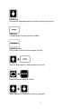
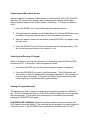
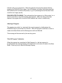
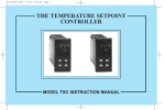
REV. 8-02
P.N. 211142
MIC 1462 1/4 DIN SETPOINT PROGRAMMER
QUICK START USER MANUAL
Copyright © 2002 by Despatch Industries
TABLE OF CONTENTS
POWER UP PROCEDURE............................................................................................. 1
KEYPAD OPERATION.................................................................................................... 1
INDICATORS .................................................................................................................. 3
Control Status Indicators.............................................................................................. 3
Run Status Indicators................................................................................................... 3
Event Indicators ........................................................................................................... 3
Mode Indicators............................................................................................................ 4
DISPLAYS....................................................................................................................... 4
Single Setpoint/Base Mode Control ............................................................................. 5
Selecting And Running A Program .............................................................................. 5
Holding A Program Manually ....................................................................................... 5
Aborting A Program...................................................................................................... 6
"End Of Program" Indication ........................................................................................ 6
MIC 1462 PROFILE PROGRAMMING............................................................................ 7
Global Parameters (common to all programs) ............................................................. 7
Global Profile Parameters Table............................................................................... 7
Program Parameters (apply as a whole to a specific program) ................................... 9
Program Profile Parameters Table............................................................................ 9
Segment Programming............................................................................................... 10
Segment Profile Parameters Table ......................................................................... 11
Exiting Profile Set Mode............................................................................................. 12
Sample Profile............................................................................................................... 12
Entering Global Parameters For The Profile.............................................................. 13
Entering Parameters Common To All Profiles............................................................ 13
Running The Profile ................................................................................................... 14
POWER UP PROCEDURE
Verify all electrical connections have been properly made before applying power to the
instrument.
If the instrument is being powered for the first time, it may be desirable to disconnect
the controller output connections. The instrument will be into control following the
power up sequence and the output(s) may turn on. During Power up, a self-test
procedure is initiated during which all LED segments in the two front panel displays
appear and all LED indicators are on. When the self-test procedure is complete, the
instrument reverts to normal operation.
Note: When power is first applied, a delay of approximately 3 seconds will be seen
before the displays light up.
KEYPAD OPERATION
MODE Key
Cycles through modes available in the instrument.
SCROLL Key
Displays the next parameter in sequence (indicated by Message display).
UP Key
Increments displayed parameter value/cycles through options.
1
DOWN Key
Decrements displayed parameter value/cycles through options.
PROF Key
Cycles through Program (profile) numbers.
RUN/HOLD Key
Runs, holds or aborts current program (profile).
Jumps to next segment, when program is running.
Selects/de-selects Manual Control.
Sets a segment to Dwell when defining a program.
2
INDICATORS
Control Status Indicators
AT - On when Self-Tune is active; flashes when PreTune is active.
ALM - Flashes when any alarm is active.
OP1 - On when primary control output is active.
OP2 - On when secondary control output (if fitted) is active.
MAN - On when Manual Control is selected.
Run Status Indicators
RUN -
On - Program running or (if HLD On also) held
Flashing - Program in Delayed state
HLD -
On - Program held
Flashing - Program in Auto-Hold
X60 -
Off - timebase = hours/minutes
On - timebase = minutes/seconds
Event Indicators
Each indicates the status (active or inactive) of a user-defined event
(Off = inactive, On = active)
3
Mode Indicators
SET - On when Profile Set Mode is entered; flashes when viewing
parameters in Configuration Mode after entry from Base Mode.
PRG - On when Profile Set Mode is entered.
DISPLAYS
4
Single Setpoint/Base Mode Control
With the Setpoint Programmer in Base Mode (i.e. with the RUN, HLD, SET, and PRG
indicators off), the two main displays will show the process variable value (upper
display) and the setpoint value (lower display - Read Only). To change the setpoint
value:
1. Press the SCROLL key until the Message Area displays Setpoint.
2. If Setpoint has been enabled in the Enable Mode, the UP and DOWN keys may
be used to change the setpoint value (in the lower display) as required.
3. When the setpoint value is set as desired, press the SCROLL key again to view
the input units.
4. Press the SCROLL key until Outputs is displayed in the message display. Use
the up and down arrow keys to turn output on or off.
Selecting And Running A Program
When no program is running, the instrument is in Base Mode and the RUN and HLD
indicators are off. In this mode, select a program as follows:
1. Hold down the PROF key until the required program number is displayed.
2. Press the RUN/HOLD key once to start the program. The RUN indicator will
then go ON, or flash if a delayed start has been programmed. The instrument is
now in Program Run Mode. In Program Run Mode, the process setpoint and
event outputs are controlled by the program selected.
Holding A Program Manually
The operator may hold or freeze a program by momentarily pressing the RUN/HOLD
key. The HLD indicator will then go on (the RUN indicator staying on) and the program
will stop execution. The program may subsequently be restarted by momentarily
pressing the RUN/HOLD key again.
HLD INDICATOR FLASHING: Before the operator holds the program manually, the
HLD indicator may start flashing. This indicates that the program is currently subject to
a Deviation-Hold. If the RUN/HOLD key is pressed (for a manual Hold), the HLD
5
indicator will go on continuously. When the operator removes the manual Hold (by
pressing the RUN/HOLD key again), the HLD indicator will either flash (indicating that
the Deviation-Hold conditions still prevail) or go off (indicating that the Deviation-Hold
conditions no longer prevail).
RUN INDICATOR FLASHING: This indicates that the program is in a Delay state (i.e. is
timed to start after a user-defined delay has elapsed). When the delay period has
elapsed, the program will run and the RUN indicator will come on continuously.
Aborting A Program
The operator may abort (i.e. terminate) the current program by holding down the
RUN/HOLD key for more than five seconds. When the program is aborted, a return is
made to the Base Mode and the Message area will read Aborted.
This message will be removed by the next key press.
"End Of Program" Indication
When the program has completed its End Segment (i.e. the last segment to
be performed), the message display will read At End, and a return is made to the Base
Mode. Press any key to clear the Message Display.
6
MIC 1462 PROFILE PROGRAMMING
Programming a profile into the MIC1462 control is broken into three categories:
GLOBAL - Those parameters common to all programs.
PROGRAM - Those which apply to a specific program as a whole.
SEGMENT - Those relevant to a specific segment in a specific program.
Global Parameters (common to all programs)
(Program Number = A, Segment Number = Blank)
1. Press the mode key until the message display reads “Prof Par”.
2. Press the scroll key once.
3. Press the Prof key until the program number display reads “A”.
4. The global parameters will now be displayed in the message display and the
setting will be displayed in the lower display.
5. Press the scroll key to go from one parameter to the next.
6. Press the up or down arrow to change the displayed setting.
The parameters common to all programs (global parameters) are presented for
editing/viewing in the following sequence:
Global Profile Parameters Table
STEP
DESCRIPTION
FUNCTION
AVAILABLE SETTING
Start On
MESSAGE
DISPLAY
Start On
1
Defines setpoint value
at start of each
program
2
Go To
Go To
3
End On
End on
Defines Base Mode
Status and end of each
program
Defines setpoint value
at end of each program
SEtP - Current Controller setpoint
value
Proc - Current Process variable
value
On - Outputs are active
Off - Outputs are inactive
4
Delay Time
Delay
Defines delay (in
hours/min) between
initiating the program
and actually starting
7
F_SP-End on Final SP value *
SEtP-End on Controller SP value
Numerical value, with the decimal
point separating the hours and
minutes.
STEP
DESCRIPTION
MESSAGE
DISPLAY
LockProg
FUNCTION
AVAILABLE SETTING
5
Program Lock
Defines whether the
operator is permitted to
change program
definitions while a
program is running/held
Defines length of power
loss before automatic
return to Base Mode
after restoration of
power, regardless of
Recovery Type.
On - No changes permitted
Off - changes permitted
6
Power Fail
Recovery
Period
Recovery
7
Power Fail
Recovery Type
Rec Type
Defines response to
restoration of power
after a power loss. This
parameter does not
appear if Recovery is
set to 0.00. These
settings can be
overridden by the
Recovery parameter.
8
Time of day
RTC Time **
9
Day of week
RTC Day **
10
External
Selection
Ext. Sel ***
Sets clock time of realtime clock option
Sets day of real-time
clock option
Defines functions which
may be controlled
externally
1:00 - 24:59
NOTE: If the real time clock
option has not been provided,
changing this value to 0.01 will
allow selection of Recovery Type.
Setting this to 00:00 will force a
return to Base Mode.
cont - Continue with mode of
operation at time of power failure.
rESt - Restart program running at
time of power failure. If one was
not running, return to Base Mode.
PFH - Setpoint and event outputs
are held at values at time of
power loss. P.F. Hold is
displayed until a key other than
RUN/HOLD is pressed. Pressing
the RUN/HOLD key will continue
the profile if one was running.
Holding this key for more than
five seconds will abort the profile.
1:00 - 24:59
Sun through SAt
nonE = No external selection
SEL = Program selection only
run = Only Run, Hold, Abort and
x60 functions
both = All program selection and
run control functions
* The Final Setpoint value for the End Segment of each program.
** Only if real-time clock is fitted.
*** Only if external options are fitted.
8
Program Parameters (apply as a whole to a specific program)
(Program Number = 1 to 8, Segment = Blank)
1. Press the mode key until the message display reads “Prof Par”
2. Press the scroll key once.
3. Press the Prof key until the desired program # is shown in the program number
display.
4. The program parameters will now be displayed in the message display and the
setting will be displayed in the lower display.
5. Press the scroll key to go from one program parameter to the next.
6. Use the up and down arrows to change the setting.
Only the parameters relevant to the displayed program number (which can be changed
using the PROG key) are presented. The parameter sequence is as follows:
Program Profile Parameters Table
STEP
DESCRIPTION
FUNCTION
AVAILABLE SETTING
Cycle Count
MESSAGE
DISPLAY
Cycles
1
Defines the number of
times the program will be
repeated
2
Deviation Hold
Dev.Hold
Selects operation of
Deviation Hold facility
(relative to setpoint)
3*
Hold Band
HoldBand
4*
Hold On
Hold on
5
Pre-x60
Pre-x60
6
Autostart time
Enable
Timer
Defines the width of the
Hold Band
Defines whether the
Deviation Hold facility is
used on ramps only,
dwells only or both
Determines whether the
timebase for the program
is pre-selected to be
hours/minutes or
minutes/seconds
Selects whether autostart
is active for this profile
1-9999
Program will repeat the set
number of times
inF = Program will repeat
indefinitely
OFF = No Deviation Hold
H_SP = Deviation Hold above
setpoint only
L_SP = Deviation Hold below
setpoint only
both = Deviation Hold above and
below setpoint
Numerical value (0.0 to span)
9
d_r = Deviation Hold on ramps
and dwells
d = Deviation Hold on dwells only
r = Deviation Hold on ramps only
nonE = No pre-selection
On = Operates MINS/SECS
OFF = Operates HRS/MINS
On
OFF
STEP
DESCRIPTION
7
Start Time**
MESSAGE
DISPLAY
Strt-ti
8
Start Day **
Strtday
FUNCTION
AVAILABLE SETTING
Determines the automatic
start time for the profile
Determines the day of the
week when start time
applies
1:00 - 24:59
OFF = manual start only
ALL = 7 days a week
Mon = Monday
tuE = Tuesday
Wed = Wednesday
thu = Thursday
Fri = Friday
SAt = Saturday
Sun = Sunday
5 dy = Mon - Fri
6 dy = Mon - Sat
* Not displayed if deviation hold is off.
** Only displayed when real-time clock is fitted, or if timer is set to On.
Editing/Viewing Parameters In Any/Each Segment In A Specific Program
(Program Number = 1 to 8, Segment Number = 1-16)
Adjust the Program Number (using the PROF key) and the Segment Number (using the
RUN/HOLD key) as required. The parameters presented will be these relevant to the program
and segment whose numbers are displayed. The parameters sequence for each segment is as
follows. Press the SCROLL key to step through each parameter.
Segment Programming
1. After all the program parameters are set for a particular program number, be sure the
desired program # is still displayed and then press the Run/Hold key. A one should now
be displayed in the segment # display.
2. The segment programming parameters will now be displayed in the message display and
the setting will be displayed in the lower display.
3. Press the up or down arrow to change the values in the lower display, press the scroll
key to go to the next parameter in the message display. Not ethe program number and
segment number displayes will remind you which program and step you are currently
programming.
4. To get 4 dashes “----“ on the display for the final SP, press the up and down arrow at the
same time.
5. To enter “End” into the time for the final segment, press down arrow to go below 0.
10
Segment Profile Parameters Table
STEP
DESCRIPTION
1
Final Setpoint
Value
3
*
MESSAGE
DISPLAY
Final SP
Segment Time
or Ramp Rate
as selected by
Segment Mode
parameter in
Configuration
Mode
Time or
RampRate
Event †
Event
FUNCTION
AVAILABLE SETTING
Defines the final value
of the setpoint for this
segment, selects a
dwell segment or
indicates a Join,
Repeat, or End
Program segment
Defines the
duration/ramp rate of
the segment or whether
this is a Join, Repeat or
End Program segment *
Numeric value (limited by SPHi and
SPLo) or (by pressing the
UP/DOWN keys simultaneously)
indicates a dwell with: “_ _ _ _” or, if
the segment is already a Join,
Repeat, or End Program segment,
as shown below
Four-digit number in the form nn.nn
(hours-minutes or minutes-seconds)
or negative values as follows (press
DOWN key):
Defines the states of the
four event outputs for
this segment
JO1 - Join to Program 1
JO2 - Join to Program 2
JO3 - Join to Program 3
JO4 - Join to Program 4
JO5 - Join to Program 5
JO6 - Join to Program 6
JO7 - Join to Program 7
JO8 - Join to Program 8
rEP - Repeat Segment
End - End Program
Four-bit binary number
(0=inactive, 1=active)
(0010 = only event 2 active)
If a segment is set to be a Join segment, a repeat segment or an End Program segment, the
next depression of the SCROLL key will set the Segment Number to 1. Otherwise, the next
depression of the SCROLL key will display the next segment final SP, or Event for the
current segment if the Event Output hardware is fitted.
† This parameter appears in the sequence only if the Event Output hardware is fitted, in which
case this parameter will be followed by the Final Setpoint Value parameter for the next
segment. If this hardware is not fitted, this parameter will be omitted from the sequence and
the segment number will be advanced, causing the Final Setpoint Value parameter for the
next segment to appear immediately.
11
Exiting Profile Set Mode
The operator may exit from Profile Set Mode by pressing the MODE key. To return to Base
Mode, press the MODE key until the Base Mode prompt appears in the Message Display, then
press the SCROLL key.
SAMPLE PROFILE
The Control is capable of storing eight (8) profiles with up to sixteen (16) segments depending
on memory. Each segment consists of a final setpoint, time, and event(s) status. The sample
profile below is set up to use Profile number 1.
12
Entering Global Parameters For The Profile
Press the mode key until Prof Par is displayed in the Message Display.
Press the SCROLL key and Cycles will be displayed with 1 displayed in the Program display.
Make changes with the UP and Down arrow keys. Press the SCROLL key to move to the next
display.
Note: the segment display must be blank. If not, press RUN/HOLD key until the segment
display is blank.
Description
Cycle Count
Deviation Hold
Time Base
Autostart Time Enable
Message Display
Cycles
Dev. Hold
Pre-x60
Timer
Setting In Lower Display
1
OFF
ON
OFF
Entering Parameters Common To All Profiles
With Cycles displayed in the Message Display, Press the PROF key until A is displayed in the
Program Display. . Make changes with the UP and Down arrow keys. Press the SCROLL key
to move to the next display.
Description
Start On
Go To
Delay Time
Program Lock
Power Fail Recovery Period
Power Fail Recovery Type
Time of Day *
Day of Week *
Message Display
Start On
Go To
Delay
Lock Prog
Recovery
Rec Type
RTC Time
RTC Day
* Only used if Real Time Clock is installed in the Control.
13
Setting In Lower Display
Proc
OFF
0.00
ON
0.01
Cont
Enter time
Enter Day
Running The Profile
Press the PROF key until 1 is displayed in the Program Display. Press the Run/HOLd key until
1 is displayed in the Segment Display and Final SP is displayed in the message display. Make
changes with the UP and Down arrow keys. Press the SCROLL key to move to the next
display.
Segment
#1
#2
#3
#4
Description
Setpoint
Ramp Time
Event Status
Setpoint
Soak Time
Event Status
Setpoint
Ramp Time
Event Status
Setpoint
Time
Event Status
Message Display
Final SP
Time
Event
Final SP
Time
Event
Final SP
Time
Event
Final SP
Time
Event
Setting In Lower Display
250
0.10
0001
250 (or “- - - -“)
1.00
0001
70
0.25
0000
70 (or “- - - -“)
End *
0000
* Press and hold the Down arrow key until “End” is displayed.
Press the mode key to return to the base mode. Press the PROF key until 1 is displayed in the
segment display. Press the Run/HOLd key to start the profile.
14