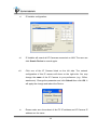
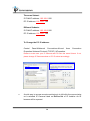
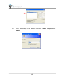
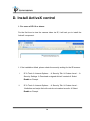
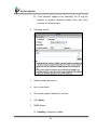
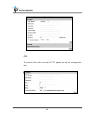
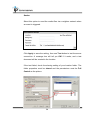
1
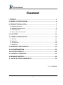
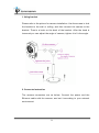
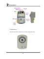
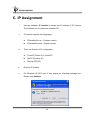
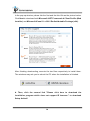
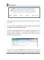
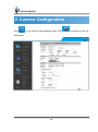
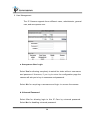
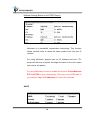
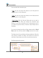
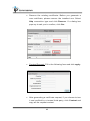
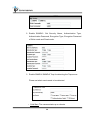
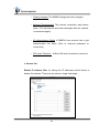
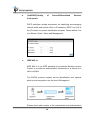
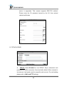
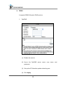
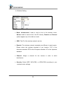
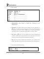
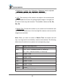
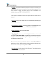
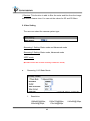
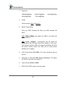
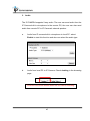
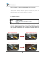
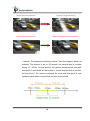
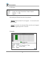
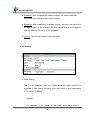
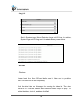
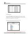
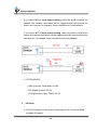
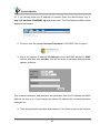
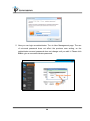
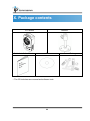
User Manual CUBE IP CAMERA WARNING TO REDUCE THE RISK OF FIRE OR ELECTRIC SHOCK, DO NOT EXPOSE THIS PRODUCT TO RAIN OR MISTURE. DO NOT INSERT ANY METALLIC OBJECT THROUGH VENTILATION GRILLS. CAUTION CAUTION RISK OF ELECTRIC SHOCK DO NOT OPEN CAUTION:TO REDUCE THE RISK OF ELECTRIC SHOCK. DO NOT REMOVE COVER (OR BACK). NO USER-SERVICEABLE PARTS INSIDE. REFER SERVICING TO QUALIFIED SERVICE PERSONNEL. COPYRIGHT THE TRADEMARKS MENTIONED IN THE MANUAL ARE LEGALLY REGISTERED TO THEIR RESPECTIVE COMPANIES. 2 Content I. PREFACE ................................................................................................................ 4 II. PRODUCT SPECIFICATIONS ................................................................................ 4 III. PRODUCT INSTALLATION ................................................................................... 7 A. MONITOR SETTINGS ............................................................................................... 7 B. HARDWARE INSTALLATION ....................................................................................... 8 C. IP ASSIGNMENT ................................................................................................... 12 D. INSTALL ACTIVEX CONTROL ................................................................................... 16 IV. LIVE VIDEO ......................................................................................................... 23 V. CAMERA CONFIGURATION ................................................................................ 26 A. SYSTEM .............................................................................................................. 27 B. NETWORK ........................................................................................................... 32 C. A/V SETTING ....................................................................................................... 60 D. EVENT LIST ......................................................................................................... 68 VI. NETWORK CONFIGURATION ........................................................................... 80 VII. I/O CONFIGURATION ........................................................................................ 82 VIII. FACTORY DEFAULT ......................................................................................... 85 IX. UNIVERSAL PASSWORD .................................................................................. 86 X. PACKAGE CONTENTS........................................................................................ 89 XI. MICRO SD CARD COMPATIBILITY .................................................................. 90 V1.1_20140328 3 I. Preface This is a 1 / 4” Mega-Pixel CMOS sensor IP camera with a built-in web server. The user can view real-time video via IE browser. It supports H.264, and M-JPEG video compression, providing smooth and high video quality. The video can be stored in the Micro SD card and playback remotely. With a user friendly interface, it is an easy-to-use IP camera which is designed for security application. II. Product Specifications HD 720P Real Time 3D+2D Digital Noise Reduction Digital Wide Dynamic Range PIR Supported WPS Supported Built-in IR LED, 5M Power Over Ethernet H.264/ M-JPEG Compression Support 2-way Audio and Speaker Micro SD Card Backup(Optional) DI/DO Support iPhone/iPad/Android Triple Streaming SDK for Software Integration Free Bundle 36 ch Recording Software 4 Hardware CPU Multimedia SoC RAM 128MB Flash 16MB Image sensor 1 / 4” Mega-Pixel CMOS sensor Lens Type 2.8mm @ F1.8 View Angle 77.79°(H), 49.55°(V) Sensitivity Color : 0.2 Lux (AGC ON) B / W: 0.1 Lux (AGC ON) ICR IR cut filter mechanism PIR Yes G.711(64K) and G.726(32K,24K) audio compression Input : Mic built-in Output : 3.5mm phone jack, or Speaker Support 2-way audio Audio IO 1 DI / 1 DO Video Output N/A Power over Ethernet Yes Power Consumption DC 12V Max: 3.24W(IR ON); 2.16W(IR Off) PoE Max: 802.3af, 4.18W (IR ON); 3.22W(IR Off) Operating Temperature 0°C ~ 45°C Dimensions 62mm x 100(mm)x 44(mm) Weight 270g IR LEDs (Option) LEDs 4 LEDs, 850nM, IR distance 8M Network Ethernet 10/ 100 Base-T Network Protocol IPv6, IPv4, HTTP, HTTPS, SNMP, QoS/DSCP, Access list, IEEE 802.1X, RTSP, TCP/IP, UDP, SMTP, FTP, PPPoE, DHCP, DDNS, NTP, UPnP, 3GPP, SAMBA, Bonjour Wireless (Option) Wireless 802.11 b/g/n. WEP,WPA-PSK,WPA2-PSK WPS Yes Power Consumption DC 12V Max: 3.90W(IR ON); 2.60W(IR Off) 5 System Video Resolution 1280x800@30fps,1280x720@30fps , 640x480@30fps, 320x240@30fps, 176x144@30fps Video Adjust Brightness, Contrast, Hue, Saturation, Sharpness, AGC, Shutter Time, Sense-up, D-WDR, Anti Fog, Lens Distortion Correction, Flip, Mirror, Day & Night adjustable, Red Gain and Blue Gain, Denoise Triple Streaming Yes Image snapshot Yes Full screen monitoring Yes Privacy Mask Yes, 3 different areas Compression format H.264/ M-JPEG Video bitrates adjust CBR, VBR Motion Detection Yes, 3 different areas Triggered action Mail, FTP, Save to SD card, DO, SAMBA Pre/ Post alarm Yes, configurable Security Password protection, IP address filtering, HTTPS encrypted data transmission, 802.1X port-based authentication for network protection, QoS/DSCP Firmware upgrade HTTP mode, can be upgraded remotely Simultaneous connection Up to 10 Micro SD card management Recording trigger Motion Detection, IP check, Network break down (wire only),schedule, DI Video format AVI, JPEG Video playback Yes Delete files Yes Web browsing requirement OS Mobile support Hardware Suggested Windows 7, 2000, XP, 2003, Microsoft IE 6.0 or above, Chrome, Safari, Firefox iOS 4.3 or above, Android 1.6 or above Intel Dual Core 2.53G, RAM: 1024MB, Graphic card: 128MB *SPECIFICATIONS ARE SUBJECT TO CHANGE WITHOUT NOTIFICATION. 6 III. Product Installation A. Monitor Settings i. Right-Click on the desktop. Select Properties ii. Change color quality to highest (32bit). 7 B. Hardware Installation 8 1. Using bracket Please refer to the picture for camera installation. Use the screws to lock the bracket to the wall or ceiling, and then connect the camera to the bracket. There’s a knob on the back of the bracket. After the knob is loosened you can adjust the angle of camera; tighten it to fix the angle. 2. Connector Instruction The camera connectors are as below. Connect the power and the Ethernet cable with the camera, and set it according to your network environment. 9 3. Adjust focus Use the rotary dial to adjust focus until the image gets clear. 10 4. PoE (Power Over Ethernet) (Optional) 802.3af, 15.4W PoE Switch is recommended Power over Ethernet (PoE) is a technology that integrates power into a standard LAN infrastructure. It enables power to be provided to a network device, such as an IP phone or a network camera, using the same cable as that used for network connection. It eliminates the need for power outlets at the camera locations and enables easier application of uninterruptible power supplies (UPS) to ensure 24 hours a day, 7 days a week operation. 11 C. IP Assignment i. Use the software, IP Installer to assign the IP address of IP Camera. The software is in the attached software CD. ii. iii. IP installer supports two languages: a. IPInstallerCht.exe:Chinese version b. IPInstallerEng.exe:English version There are 3 kinds of IP configuration. a. Fixed IP (Public IP or Virtual IP) b. DHCP (Dynamic IP) c. Dial-up (PPPoE) iv. Execute IP Installer v. For Windows XP SP2 user, it may popup the following message box. Please click Unblock. 12 vi. IP Installer configuration: vii. IP Installer will search all IP Cameras connected on LAN. The user can click Search Device to search again. viii. Click one of the IP Camera listed on the left side. The network configuration of this IP camera will show on the right side. You may change the name of the IP Camera to your preference (e.g.: Office, warehouse). Change the parameter and click Submit then click OK. It will apply the change and reboot the Device. ix. Please make sure the subnet of the PC IP address and IP Camera IP address are the same. 13 The same Subnet: IP CAM IP address: 192.168.1.200 PC IP address: 192.168.1.100 Different Subnets: IP CAM IP address: 192.168.2.200 PC IP address: 192.168.1.100 To Change the PC IP address: Control PanelNetwork ConnectionsLocal Area Connection PropertiesInternet Protocol (TCP/IP) Properties Please to make sure your IP Camera and PC have the same Subnet. If not, please change IP Camera subnet or PC IP subnet accordingly. x. A quick way to access remote monitoring is to left-click the mouse twice on a selected IP Camera listed on Device list of IP Installer. An IE browser will be opened. 14 xi. Then, please key in the default username: admin and password: admin. 15 D. Install ActiveX control 1. For users of IE 6.0 or above: For the first time to view the camera video via IE, it will ask you to install the ActiveX component. 1. If the installation failed, please check the security setting for the IE browser. i. IE Tools Internet Options… Security Tab Custom Level… Security Settings Download unsigned ActiveX controls Select Enable or Prompt. ii. IE Tools Internet Options… Security Tab Custom Level… Initialize and script ActiveX controls not marked as safe Select Enable or Prompt. 16 1 2 3 4 17 5 When popup the following dialogue box, click Yes. 2. You can choose another way: Go to: IE→Tools → Internet Options… → Security Tab → Trusted sites → Add the IP address and click OK. In the site list you can key one single IP address or a LAN address. For example, if you add 192.168.21.*, all the IP address under .21 LAN will be regarded as trusted sites. 18 2. To Non-IE Web Browser Users If you use Firefox or Google chrome to access the IP camera but fail to watch the live video, please follow the steps to install necessary tools: (The following pictures are based on chrome.) a. You may see the prompt message as the picture below. First, click the link: Firstly, please install Microsoft Visual C++ 2010 Redistributable Package (x86). The link conducts you to the Microsoft official site where you can download the tools. Please select the language and click download. 19 In the pop-up window, please tick the first and the third file as the picture below. Click Next to download both Microsoft .NET Framework 4 Client Profile (Web Installer) and Microsoft Visual C++ 2010 Redistributable Package (x64). After finishing downloading, execute the two files respectively to install them. The windows may ask you to reboot the PC when the installation is finished. b. Then, click the second link "Please click here to download the installation program which does not support IE browser." to download Setup ActiveX. 20 After finishing the downloading, execute the files to install ActiveX. Then restart the browser. c. If you execute the steps above but still cannot see the live video normally, please try the following solution: Search for the file np_hoem_x.dll in your system disk. For Windows XP users, please go to Start → Search → Search for All files and folders and key-in np_hoem_x.dll. For Windows 7 users, please use the search bar on the top-right of the Windows Explorer. Delete all the files named np_hoem_x.dll. They're the ActiveX control tools installed in your computer, but the old version of ActiveX might not compatible with the new version of browser. Therefore, they need to be deleted in order to 21 install the latest ActiveX control. Start your web browser, and repeat the step 2-b: Download the installation program which does not support IE browser to download and install ActiveX. 22 IV. Live Video Start an IE browser, type the IP address of the IP camera in the address field. It will show the following dialogue box. Key-in the user name and password. The default user name and password are admin and admin. When the IP Camera is connected successfully, it shows the following program interface. 23 1. Get into the administration page. 2. Video Snapshot. 3. Show the system time, video resolution, and video refreshing rate. 4. Adjust image: 1/2x, 1x, 2x. 5. Selects the video streaming source: If the streaming 2 is closed, this function will not be displayed. 6. Tick on “Chatting” for enabling two-way audio. 7. Shows how many people are connected to this IP camera. 8. Control the relay output connected to this camera. Double-clicking on the video will change the view to full screen mode. Press Esc or double-click the video again for changing back to normal mode. Right-Click the mouse on the video, it will show a pop-up menu. I. Snapshot: Save a JPEG picture 24 II. Record Start: Record the video in the local PC. It will ask where to save the video. To stop recording, right-click again. Select Record Stop. The video format is AVI. Use Microsoft Media Player to play the recorded file. III. Mute: Turn-off the audio. Click again to turn on it. IV. Full Screen: Full-screen mode. V. Zoom: Enable the zoom-in and zoom-out functions. First, select Enable digital zoom option within the pop-up dialogue box and then drag and drop the bar to adjust the zoom factors. VI. Frame Buffm Sec: This function is to build a temporary buffm to accumulate several video frames. This function can make video smooth-going when the Network speed is slow and lag. If you select 100, then it plays video 100 mSec after receiving images from camera. The slower the Network is the bigger value should be selected. The available values are: NULL, 100, 200, 300, 400, and 500. The default value is null. 25 V. Camera Configuration Click to get into the administration page. Click video page. 26 to go back to the live A. System I. System Information a. Server Information: Set up the camera name, select language, and set up the camera time. 1. Server Name: This is the Camera name. This name will be shown on the IP Installer. 2. Select language: English, Traditional Chinese, and Simplified Chinese can be selected. When it changes, it will show the following dialogue box to confirm the language changing. b. OSD Setting: Select a position where the date & time stamp / text are shown on the screen. Moreover, click Text Edit for changing the OSD content, including text size and alpha. Finally, click the Upgrade button to keep the settings. 27 c. Server time setting: Select the options to set up time - NTP, Synchronize with PC’s time, Manual, The date and time remain the same. 28 II. User Management The IP Camera supports three different users, administrator, general user, and anonymous user. a. Anonymous User Login: Select Yes for allowing everybody to watch live video without username and password. However, if you try to enter the configuration page the camera will ask you to key-in username and password. Select No for requiring a username and login to access the camera. b. Universal Password: Select Yes for allowing login to this IP Cam by universal password. Select No for disabling universal password. 29 c. Add user Type the user name and password, then click Add/Set. The guest user can only browse live video page and is not allowed to enter the configuration page. d. Click “edit” or “delete” in the user list to modify them. The system will ask you to key-in the password in the pop-up window before you edit the user information. III. System update a. To update the firmware online, click Browse… to select the 30 firmware. Then click Upgrade to proceed. b. Reboot system: re-start the IP camera c. Factory default: delete all the settings in this IP camera. d. Setting Management: The user may download the current settings to PC, or upgrade from previous saved settings. 1. Settings download: Right-click the mouse button on Setting Download Select Save AS… to save current IP Camera settings in PC Select saving directory Save 2. Upgrade from previous settings Browse search previous settings open upgrade Settings update confirm click index.html. for returning to main page 31 B. Network I. IP Settings IP Assignment The IP Camera supports DHCP and static IP. a. DHCP: The IP Camera will get all the network parameters automatically. b. Static IP: Type-in the IP address subnet mask, gateway, and DNS manually. 32 IPv6 Assignment You can manually key in IPv6 address, enable DHCPv6, and use automatically generated IPv6 address simultaneously. Manually setup the IPv6 address: Key in Address, Gateway, and DNS. DHCPv6: If you have a DHCPv6 server, enable it to assign the IPv6 automatically. The assigned IP address will be displayed beside the column. Automatically generated IPv6 Address: Indicates a virtual IPv6 address generated automatically by the IP camera. This virtual IPv6 address cannot be used on WAN. To use IPv6 address to access the IP camera, open the web browser, and key-in the [IPv6 address] in the address bar. The [ ] parentheses mark is necessary. 33 a. Port Assignment: The user may need to assign different port to avoid conflicts when setting up the IP. b. Web Page Port: setup web page connecting port and video transmitting port (Default: 80) c. HTTPs Port: setup the https port(Default: 443) UPnP This IP camera supports UPnP, if this service is enabled on your computer, the camera will automatically be detected and a new icon will be added to My Network Places. UPnP Port Forwarding : Enable UPnP Port Forwarding for accessing the IP Camera from the Internet; this option allows the IP Cam to open ports on the router automatically so that video streams can be sent out from a LAN. There are three external ports for being set: Web Port, Http Port and RTSP port. To utilize of this feature, make sure that your router supports UPnP and is activated. 34 Note: UPnP must be enabled on your computer. Please follow the procedure to activate UPnP: <Approach 1> 1. open the Control Panel from the Start Menu 2. Select Add/Remove Programs 3. Select Add/Remove Windows Components and open Networking Services section 4. Click Details and select UPnP to setup the service 5. The IP device icon will be added to My Network Places 6. The user may double click the IP device icon to access IE browser <Approach 2> 1. Open My Network Space 2. Click Show icons for networked UPnP devices in the tasks column on the left of the page. 3. Windows may ask components. Click Yes. 35 your confirmation for enabling the 4. Now the IP device is displayed under the LAN. Double-click the icon to access the camera via web browser. To disable the UPnP, click Hide icons for networked UPnP devices in the tasks column. 36 RTSP setting If you have a media player that supports RTSP protocol, you can use it to receive the video streaming from IP camera. The RTSP address can be set for two streamings respectively. Please jump to 1. RTSP Server: enable or disable Disable means everyone who knows your camera IP Address can link to your camera via RTSP. No username and password are required. Under Basic and Digest authentication mode, the camera asks the user to give username and password before allows access. The password is transmitted as a clear text under basic mode, which provides a lower level of security than under “digest” mode. Make sure your media player supports the authentication schemes. 2. RTSP Port: setup port for RTSP transmitting (Default: 554) 3. RTP Start and End Port: in RTSP mode, you may use TCP and UDP for connecting. TCP connection uses RTSP Port (554). UDP connection uses RTP Start and End Port. 37 Multicast Setting (Based on the RTSP Server) Multicast is a bandwidth conservation technology. This function allows several users to share the same packet sent from the IP camera. For using Multicast, appoint here an IP Address and port. TTL means the life time of packet, the larger the value is, the more users can receive the packet. For using Multicast, be sure to enable the function Force Multicast RTP via RTSP in your media player. Then key in the RTSP path of your camera: rtsp ://( IP address)/ to receive the multicast. ONVIF 38 1. Choose your ONVIF version and settings. Under ONVIF connection, the video will be transmitted by RTSP. Be sure to enable the RTSP server in IP setting, otherwise the IP Cameras will not be able to receive the video via ONVIF. 2. Security By selecting Disable, the username and password are not required for accessing the camera via ONVIF. By selecting Enable the username and password are necessary. 3. RTSP Keepalive: When the function is enabled, the camera checks once in a while if the user who is connected to the camera via ONVIF is still connected. If the connection has been broken, the camera will stop transmitting video to the user. Bonjour This function allows MAC systems to connect to this IP camera. On Bonjour Name Key-in the name here. 39 The web browser Safari also has a Bonjour function. Tick Include Bonjour in the bookmark setting, for the IP camera to appear under the bonjour category. Click the icon to connect to the IP camera. So far the Bonjour function on Safari browser doesn't support HTTPS protocol. If on the camera you select https, the camera will appear on Safari's bookmarks but it cannot be accessed. LLTD If your PC supports LLTD, enable this function for allowing checking the connection status, properties, and device location (IP address) in the network map. 40 If the computer is running Windows Vista or Windows 7, you can find LLTD through the path: Control Panel → Network and Internet → Network and Sharing Center → Click See full map. II. Advanced: a. Https (Hypertext Transfer Protocol Secure) When the users access cameras via Https protocol, the transmitted information will be encrypted so that the security level is arisen. 41 You can select the connection type. • Http: the user can access the camera via the Http path but cannot access it via the Https path. • Https: the user can access the camera via the Https path but cannot access it via the Http path. • Http & Https: Both the Http and Https path can be used to access the camera. When you change the connection type settings, it may cause connection error or disconnection error if you switch the protocol directly. Therefore, Http & Https mode is necessary. If you want to change from Http to Https, please switch to Http & Https mode first, and then switch to Https mode and vice versa. The Https protocol has certificate verifying mechanism. When the user access a website via Https, the browser wi ll check the certificate of that domain and verify its trustiness and secure. Certificate generation process: 42 Remove the existing certificate: Before you generate a new certificate, please remove the installed one. Select Http connection type and click Remove. If a dialog box pops up to ask you to confirm, click Yes. Created Request: Fill-in the following form and click apply. After generating a certificate request, if you choose to turn it and verified by a trusted third-party, click Content and copy all the request content. 43 According to the certificate source, there are two ways to install the certificate: If you had sent the certificate request for signing and receiving a signed certificate, click browse and find the certificate file in your computer. Click Apply to install it. If you choose to generate a self-signed certificate, fill-in the following forms and set the validity day, click Apply to finish installed it. 44 After finishing the installation, you can click Content to call out and check the certificate content. To use Https to access the camera, open your browser, and key-in https:// (IP address)/ in the address bar. Now your data will be transmitted via encrypted communications. The browser will check your certificate status. It might show the following warning message: Meaning that certificate is self-signed or signed by a distrusted institution. Click Proceed anyway for continuing to the camera page. b. SNMP (Simple Network Management Protocol) 1. Enable SNMPv1 or SNMPv2 and write the name of both Write Community and Read Community. 45 2. Enable SNMPv3. Set Security Name, Authentication Type, Authentication Password, Encryption Type, Encryption Password of Write mode and Read mode. 3. Enable SNMPv1/SNMPv2 Trap for detecting the Trap server. Please set what event needs to be detected. • Cold Start: The camera starts up or reboots. 46 • Setting changed: The SNMP settings has been changed. • Network Disconnected: The network connection was broken down. (The camera will send trap messages after the network is connected again) • V3 Authentication Failed: A SNMPv3 user account tries to get authentication but failed. (Due to incorrect password or community) • SD Insert / Remove: A Micro SD card is inserted or removed. c. Access list: Enable IP address filter for setting the IP addresses which allows or denies this camera. There are two options, single and range. 47 d. QoS/DSCP(Quality of Server/Differentiated Services Code-point): DSCP specifies a simple mechanism for classifying and managing network traffic and provide QoS on IP networks. DSCP is a 6-bit in the IP header for packet classification purpose. Please define it for Live Stream, Event / Alarm and Management. e. IEEE 802.1x: IEEE 802.1x is an IEEE standard for port-based Network Access Control. It provides an authentication mechanism to a device on a LAN or WLAN. The EAPOL protocol support service identification and optional point to point encryption over the local LAN segment. Please check what version of the authenticator and authentication 48 server is supported. This camera supports EAP-TLS method. Please enter the ID, password issued by the CA, then upload related certificates. III. PPPoE & DDNS: a. PPPoE: Select Enabled to use PPPoE. Key-in Username and password for ADSL connection. Send mail after dialed: When connect to the internet, it will send a mail to a specific mail account. For mail setting, please refer to Mail and FTP settings. 49 b. DDNS: It supports DDNS (Dynamic DNS) service. 1. DynDNS: (1) Enable this service (2) Key-in the DynDNS server name, user name, and password. (3) Set up the IP Schedule update refreshing rate. (4) Click Apply 50 (5) If the schedule update is too frequently, the IP may be blocked. In general, schedule update every day (1440 minutes) is recommended 2. Camddns service: 1. Please enable this service 2. Key-in user name. 3. IP schedule update default at 5 minutes 4. Click Apply. 3. DDNS Status (1) Updating: Information update 51 (2) Idle: Stop service (3) DDNS registration successful, can now log by http://<username>.ddns.camddns.com: Register successfully. (4) Update Failed, the name is already registered: The user name has already been used. Please change it. (5) Update Failed; please check your internet connection: Network connection failed. (6) Update Failed, please check the account information you provided: The server, user name, and password may be wrong. IV. Server settings There are three choices of server types available: Email, FTP and SAMBA. Select the item for display detailed configuration options. You can configure either one or all of them. To send out the video via mail of FTP, please set up the configuration first. 52 FTP To send out the video via mail of FTP, please set up the configuration first. 53 Samba Select this option to send the media files via a neighbor network when an event is triggered. Click Apply to save the setting, then use Test button to test the server connection. A message box will tell you OK! if it works, and a test document will be created in the location. If the test failed, check the sharing setting of your location folder. The folder properties must be shared and the permissions must be Full Control as the picture. 54 V. Wireless Setting (Optional): Support 802.11 b/g/n For setting up the IP camera via wireless network, first, use the Ethernet cable to connect the camera. After finishing the wireless settings and saving them, remove the Ethernet cable. Note: The IP address is the same under both wireless and wired network. If the Ethernet cable is plugged in the camera, the IP camera will use it to link to the Internet instead of the wireless router. a. Status of Wireless Networks The camera scans and shows the SSID, Mode, Security, and Signal strength of the wireless network. 55 b. Wireless Setting Mode: Infrastructure” mode is used to link to the wireless router. Ad-hoc mode is used to link to the PC directly. Domain and Channel options appear only in the Ad-hoc mode. SSID: The ID of the wireless network service. Domain: The wireless network standards are different in each region. Please select the wireless standard of you location. FCC is the American standard. ETSI is the European standard. JP is the Japanese standard. Channel: Assign a channel for the camera in order to avoid interference. Security: Select WEP, WPA-PSK, or WPA2-PSK according to your wireless router settings. 56 c. WEP Setting Authentication: Open System or Shared Key, according to your wireless router. Encryption: The option determines the length of the key password. In HEX type, 10 characters are allowed if you select 64 bit; 26 characters are allowed if you select 128bit; In ASCII type, 5 characters are allowed if you select 64 bit; 13 characters are allowed if you select 128bit. Key Type: In HEX type, the key password can only be hexadecimal numbers. In ASCII type, the key password can be any letter and number. (Capital and lowercase letters are regarded as different.) Key 1~4: Key in the key password according to your wireless router setting. The length and type must be consistent with the settings above. d. WPA-PSK/ WPA2-PSK Setting 57 Encryption: TKIP or AES, according to your wireless router. Pre-Shared Key: Key in the key password here according to your wireless router setting. Any letters and numbers are allowed. (Capital and lowercase letters are regarded as different.) e. WPS WPS (Wi-Fi Protected Setup) is an interface standard that allows users to easily establish wireless network, and be free from complicated security setting. Please follow the steps for starting WPS. The menu and usage of every router may be different from the sample pictures. Set up the SSID and the pre-shared key on your wireless router. WPS only supports WPA/WPA2 security. Do not select WEP security. Plug-in the power adapter to the IP camera. Use Ethernet cable to connect the IP camera to the PC or network. Enter into the wireless setting page, and check if the SSID of your wireless router is listed in Status of Wireless Networks. If yes, continue toward next step. No other wireless setting is needed. Access your router, and press the Connect button of the PBC (Push Button Configuration) setting page on your router. Then press the WPS button on the back of camera. The light start flashing. 58 above the WPS button will When it finally stops flashing and lights constantly, it means the WPS connection is successful. Refresh the wireless setting page on the camera; you will see that the security settings have been already automatically completed. Meanwhile you may see a message on your router page to inform you the connection is OK. Now you can remove the Ethernet cable from the IP camera. If the light finally stops flashing but the lights are off, it means the WPS connection failed. Check your wireless router setting, and make sure the SSID of the wireless router is found by the camera and listed in Status of Wireless Networks. 59 C. A/V Setting 1. Image Setting For security and privacy purposes, there are three areas that can be set up for privacy. Click the Area button first, and then drag an area on the above image. Remember to save your settings. The masked area will not shown on both live view and recording image. Please refer to the details below for image settings: 60 a. Brightness, Contrast, Hue, Saturation, Sharpness can be adjusted here. The available values are: -4, -3, -2, -1, 0, 1, 2, 3, 4 b. AGC: The sensitivity of the camera can adjust to the environmental lighting. Enable this function for getting brighter image on low light, but the level of noise may also increase. The available values are: 8x, 16x, 24x, 32x c. Shutter Time: Choose the location of your camera or a fixed shutter time. The shorter the shutter time is the less light the camera receives and the image becomes darker. Note: When you select a number in Shutter Time, the shutter time will vary in a range and be controlled by camera automatically. The following table shows the shutter time options and corresponding range. Option Outdoor Indoor Shutter Time Range (sec.) 1/10000 ~ Selected number in Sense-up" NTSC: 1/120 ~ Selected number in "Sense-up" PAL: 1/100 ~ Selected number in "Sense-up" 1/30 1/10000 ~ 1/30 1/50 1/10000 ~ 1/50 1/60 1/10000 ~ 1/60 1/100 1/10000 ~ 1/100 1/125 1/10000 ~ 1/125 1/250 1/10000 ~ 1/250 1/500 1/10000 ~ 1/500 1/1000 1/10000 ~ 1/1000 1/10000 1/10000 * Sense-up options: 1/30, 1/15, 1/10 61 d. D-WDR: This function enables the camera to reduce the contrast in the view to avoid dark zones as a result of over and under exposure. If the Input resolution is 30fps, the default value is fixed on ENABLED. The available values are: OFF, 1, 2, 3, 4, 5, 6, 7, 8 If the D-WDR is enabled the values for bright, dark and contrast can be adjusted. e. Anti Fog: Improve the image clarity on environments presenting high levels of fog or smoke. f. Lens Distortion Correction: Correct the image in the borders due to the lens angles. The available values are: OFF, 1, 2, 3, 4, 5, 6, 7, 8 g. Video Orientation: Flip or mirror the image. h. Day & Night: The camera can detect the light level of the environment. If you choose Light Sensor Mode, the image will be turned black and white at night in order to keep a clear image. To set light sensor mode, appoint a Lux standard of switching D/N. The current Lux value is provided for reference. Under Times Mode the switch time of Color / Black and white will be according to the given time. You can also control it by choosing Color or B/W. i. Red / Blue gain: Set the values for Red / Blue gain. The available values are: -5, -4, -3, -2, -1, 0, 1, 2, 3, 4, 5 62 j. Denoise: This function is able to filter the noise and blur from the image and show a clearer view. You can set the values for 2D and 3D filters. 2. Video Setting The user can select the camera system type Streaming 1 Setting: Basic mode and Advanced mode Streaming 2 Setting: Basic mode, Advanced mode 3GPP mode (Max Video Frame Rate for both streaming combined is 30 FPS) a. Streaming 1 & 2 Basic Mode: 1. Resolution: 1280x800@30fps, 320x240@30fps, 1280x720@30fps, 176x144@30fps 63 640x480@30fps, 2. Profile Chose between Main or Baseline 3. Quality There are 5 levels: Best/ High/ Standard/ Medium/ Low The higher the quality is, the bigger the file size is. Not good for internet transmission. b. 4. Video Frame Rate (5~30 FPS): The video refreshing rate per second. 5. Video Format: H.264 or JPEG 6. RTSP Path: RTSP output name Streaming 1 & 2 Advanced Mode: 64 1. Resolution 1280x800@30fps, 320x240@30fps, 2. 1280x720@30fps, 176x144@30fps 640x480@30fps, Profile Chose between Main or Baseline 3. Bitrate Control Mode There are CBR (Constant Bit Rate) and VBR (Variable Bit Rate) CBR: 32Kbps~8Mbps (the higher the CBR is, the better the video quality is) VBR: 1(Low) ~10(High) – Compression rate, the higher the compression rate, the lower the picture quality is; vise versa. The balance between VBR and network bandwidth will affect the picture quality. Select the VBR rate to avoid picture breaking up or lagging. 4. Video Frame Rate (5~30 FPS): The video refreshing rate per second. 5. GOP Size (1, 1/2, 2) X FPS: Group of Pictures. The higher the GOP is, the better the quality is. 6. Video Format: H.264 or JPEG 7. RTSP Path: RTSP output connecting path 65 c. 3GPP Streaming mode: 1. Resolution: 640x480@15fps, 320x240@15fps, 176x144@15fps 2. Video Bitrate: 32Kbps~1Mbps (the higher Video Bitrate is, the better the video quality is) 3. Video Frame Rate The video refreshing rate per second. 4. RTSP Path: RTSP output name 66 3. Audio The IP CAMERA supports 2-way audio. The user can send audio from the IP Camera built-in microphone to the remote PC; the user can also send audio from remote PC to IP Camera’s external speaker. a. Audio from IP camera built-in microphone to local PC: select Enable to start this function and also can select the audio type. b. Audio from local PC to IP Camera: Check chatting in the browsing page. The Audio will not be smooth when the SD card is recording. 67 D. Event List The IP Cam provides multiple event settings. 1. Event Setting a. Motion Detection To enable motion detection, please tick Area 1/2/3. Click Area 1/2/3 in Area Setting, and draw an area on the preview screen. When motion is detected in the area, the word Motion! will be displayed on the live screen. The camera will send video or snapshot to specific mail addresses, trigger the output device, or save video to FTP/ Micro SD card/ Samba. By selecting save to SD card, the video or snapshot will be saved to Micro SD card. Also, by ticking E-mail/ FTP/ Samba on the Log option, the motion detection log will be sent to E-mail/ FTP/ Samba simultaneously. • Interval: For example, selecting 10 sec. Once the motion is detected and 68 action is triggered, it cannot be triggered again within 10 seconds. • Based on the schedule: When the option box is ticked, only during the selected schedule time the motion detection is enabled. b. Tampering Detection When the camera view is covered, moved, hit by strong light, or out of focus, the tampering detection will be triggered, and send snapshot or video to mail/FTP/Samba/SD card, or trigger the external alarm. For example: Before Tampering Detection Tampering Triggered (Defocused) Before Tampering Detection Tampering Triggered (Lens Covered) 69 Before Tampering Detection Tampering Triggered (Glare) Before Tampering Detection Tampering Triggered (Camera Moved) • Interval: The tampering detecting interval. Take the diagram below as example. The interval is set for 30 second; the camera lens is covered during 10 - 40 sec. At time point B, the camera compares the view with time point A, and sends an alarm when it founds that the lens is covered. At time point C, the camera compares the view with time point B, and sends an alarm when it founds that the lens is uncovered. 70 c. Record File When an event occurs, the IP camera will record a video clip or take snapshot, and then send to mail/ FTP/ Samba. Select the file format to be saved. • AVI File (with Record Time Setting): Save AVI video file. The video length is according to the value set in Record Time Setting. • JPEG Files (with Record Time Setting): Only when selecting JPEG in streaming 1 video format of Video Setting, this option can be enabled. Select this option to save several JPEG picture files. The successive picture files cover a period of time according to the value set in Record Time Setting. • JPEG File (Single File with Interval Setting): Save single JPEG picture file when the event occurs. d. Record Time Setting When an event occurs, the IP camera can record a video clip or take a snapshot, and then send it via mail/ FTP/ Samba. Select the video recording length before and after the event is detected. 71 e. Network Dis-connected The IP Cam will scan the network. The image will be record to the SD card after the IP Camera detects network dis-connected, if set “Save to SD card”. f. Network IP check After enable IP Check, the IP camera can check if the network server is connecting. If the IP camera checking failed, the image will be recorded to the SD card. 72 g. PIR Setting After enabling the PIR select the action to be performed. • Wave file: Select the Wave File to be triggered. You can test the audio before setting it. • Interval: For example, when selecting 10 sec, once the event is triggered, it cannot be triggered again within 10 seconds. 2. Schedule 73 a. Schedule: After complete the schedule setup, the camera data will be recorded according to the schedule setup. b. Snapshot: After enable the snapshot function; the user can select the storage position of the snapshot file, the interval time of the snapshot and the reserved file name of the snapshot. c. Interval: The interval between two snapshots. 3. I/O Setting a. Input Setting: The IP Cam supports input and output. When the input condition is triggered, it can trigger the relay; send the video to mail addresses /FTP server / SAMBA. • Interval: For example, if you select 10 sec here, once the motion is 74 detected and action is triggered, it cannot be triggered again within 10 seconds. • Based on the schedule: When the option box is ticked, only during the selected schedule time the I/O is enabled. That is, for example, the 11th hour of Monday has not been colored in the schedule table, then no action will be triggered even if the camera detects input signal during 11:00~12:00 on Monday. b. Output Setting: The output mode affects the DO or relay out duration. ON/Off Switch: The camera triggers the external device and lasts for 10 seconds. You can turn off the alarm manually by clicking off at the right bottom of the live video page. Time Switch: The camera triggers the external device and lasts for certain time according to the internal setting, and the user is not allowed to break off the alarm manually. 75 4. Log List Sort by System Logs, Motion Detection Logs and I/O Logs. In addition, System Logs and I/O Logs won’t lose data due to power failure. 5. SD card a. Playback Please Insert t h e Micro SD card before use it. Make sure t o push the Micro SD card into the slot completely. Click the date listed on this page for showing the video list. The video format is AVI. Click the video to start Microsoft Media Player to play it. To delete the video, check it, and then click Del. 76 b. SD Management Choosing The 1st day means the recoding file will be kept for one day. Example: It is five o’clock now. Choose The 1st day. The files will be kept from five o’clock yesterday to five o’clock today. The oldest file will be deleted if the Micro SD card is full. Note:The use of the SD card will s l i g h t l y affect the operation of the IP Camera, such as affecting the frame rate of the video. 77 c. Copy to PC You can insert the Micro SD card to the PC and read the files directly, or use FlashGet instead to download the files from the IP camera. (In this way you do not need to pull out the Micro SD card from the camera.) To use FlashGet for downloading image and video data from the Micro SD card, please follow the steps: (i) Enter data list and right-click Files link daily, select save target as… then save the link list to PC. (ii) Open FlashGet, select File → Import → Import list, and find the link list file you just saved. The file name may be called SD_list. (iii) FlashGet will show you the link list, and you can tick the files you want to copy to your PC. Give the directory path in the new download window, and remember to enable Login to Server: key in the IP 78 Camera username and password. (iv) Click “OK” to start download. • FlashGet is free software that can be downloaded from FlashGet official website. The example above is based on FlashGet ver.1.9.6. 79 VI. Network Configuration I. Configuration 1: a. Internet Access: ADSL or Cable Modem b. IP address: One real IP or one dynamic IP c. Only the IP Camera is connected to the internet d. For fixed real IP, set up the IP into IP Camera. For dynamic IP, start PPPoE. II. Configuration 2: a. Internet Access: ADSL or Cable Modem b. IP address: More than one real IP or one dynamic IP c. IP Camera and PC connect to the internet d. Device needed: Switch Hub 80 e. For fixed real IP, set up the IP into IP Camera and PC. For dynamic IP, start PPPoE. III. Configuration 3: a. Internet Access: ADSL or Cable Modem b. IP address: one real IP or one dynamic IP c. IP Camera and PC connect to the internet d. Device needed: IP sharing e. Use virtual IP, set up port forwarding in IP sharing. 81 VII. I/O Configuration 1. I/O Connection a. Please connect the GND & DO pin to the external relay (buzzer) device. b. Please connect the GND & DI pin to the external trigger device. When no event occurs, the DO output is 5V (DO and GND are disconnected). When the camera detects events it will trigger and external alarm, DO output is 0V (DO and GND are connected). 82 If you select N.O on Input sensor setting, when the switch contacts are opened, the camera input alarm will be triggered and will execute the action user has set, for example, send a snapshot to E-mail address. If you select N.C in Input sensor setting, when the switch contacts are closed, the camera input alarm will be triggered and will execute the action user has set, for example, send a snapshot to E-mail address. c. I/O PIN definition • GND (Ground): Initial state is LOW • DO (Digital Output): DC 5V • DI (Digital Input): Max. 50mA, DC 5V 2. I/O Setup a. Click I/O Setting from the system setup page via IE, and check Out1 to enable I/O signal. 83 b. Output Test After the external input and output hardware is installed, you can use the Relay Out bottom on the live video page to test if DO / Relay Out works. (i) On Off Switch mode: Clicking ON will trigger the external output device for 10 seconds. For example, your alarm buzzer will continuously ring for 10 seconds. After 10 seconds the buzzer stops ringing, or you can manually break off the output signal by clicking OFF. 84 (ii) Time Switch mode: Click Pulse, the camera will trigger the external output device for several seconds; the duration length is according to the interval setting in Output Setting. VIII. Factory Default If you forget your password, please follow the steps to revert back to default value. • Remove power adapter and Ethernet cable from the camera. • Press and hold the Default button on the back of the camera, as the picture. 85 • Connect the power to the camera again. It will take around 30 seconds for the camera to boot. • Remove the wire and plug in the Ethernet cable after the camera finishes booting. • Re-login the camera by using the default IP (http://192.168.1.200), and user name: admin, password: admin. IX. Universal Password If you forgot the password of your IP camera, you can reset the camera to factory default, or follow the procedure below to generate a universal password. Note: Universal password will be valid only when you enable the function in User Management. 1. First, you need to know the IP address and MAC of your IP camera. You can use IP installer to scan the LAN, and see the IP address and MAC on the side column. 86 Or, if you already know the IP address of camera: Open the web browser, key in http:// (IP address) /GetIPMAC.cgi and press enter. The IP address and MAC will be displayed on browser. 2. Find the .html file named Universal Password in CD-ROM. Click to open it. 3. Key in the camera IP address IP Address column and MAC address in MAC column, and then click encoder. You will see a set of username and password appear, as below: The universal username and password are generated from the IP address and MAC address you key-in, so if you change the camera IP address the universal password changes, too. 4. Take the generated username and password. Use them to log into the camera. 87 5. Now you can login as administrator. Turn to User Management page. The use of universal password does not affect the previous user setting, so the administrator account password does not change until you edit it. Please click Edit to give a new administrator password. 88 X. Package contents IP Camera Quick Installation Guide Bracket CD • The CD includes user manual and software tools 89 Screw Package XI. Micro SD Card Compatibility The following are the recommended Micro SD Cards: Transcend SanDisk SDHC class4 16GB SDHC class4 32GB SD class4 16GB SD class4 32GB SDHC class6 4GB SDHC class6 8GB SDHC class6 16GB SD class6 4GB SD class6 8GB SD class6 16GB SDHC class4 class10 4GB 4GB SDHC class4 class10 8GB 8GB SDHC class4 class10 16GB SDHC 16GB class4 32GB 90