1
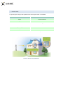
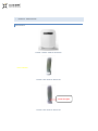
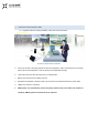
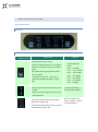
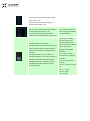
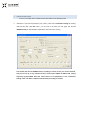
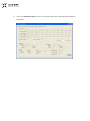
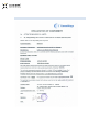
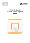
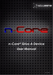
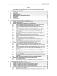
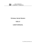
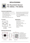
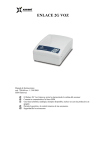
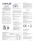
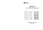
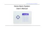
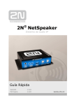
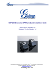
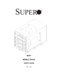
USER MANUAL OF UMTS ICS PICO
REPEATER
CONTENT
1.
Product Introduction................................................................................................................ 3
2.
Usage scope ............................................................................................................................. 4
3.
Characteristics.......................................................................................................................... 5
4.
Specifications ........................................................................................................................... 6
5.
Product Description ................................................................................................................. 8
6.
Installation instructions ........................................................................................................... 9
7.
Indicator Instruction Table ..................................................................................................... 10
8.
Local Setup steps ................................................................................................................... 12
9.
National restrictions .............................................................................................................. 14
10.
Declaration of Conformity ..................................................................................................... 15
11.
Contact Details ...................................................................................................................... 16
1.
PRODUCT INTRODUCTION
The ICS Pico Repeater provides an affordable solution to solve the indoor signal coverage problems in
UMTS system due to signal fading and attenuation caused by architecture obstacles. And its easy
installation and maintenance can help carrier get fast return.
The Pico-repeater is working as a relay between the BTS and mobiles. The UMTS ICS Pico is
micro-power digital wireless repeater, with its interference cancellation system (ICS) feature, it can
provide UMTS signal for offices, meeting rooms , houses , and a variety of other indoor space. The
device is compact, easy to install, is the most simple and quick way for operators to improve the signal.
The UMTS ICS Pico realizes function of LNA, frequency conversion, A/D, D/A, RF amplification, DSP,
IF filter, and it reduces the isolation requirement by adopting digital self-adaptive technology; the
equipment has built-in donor antenna and service antenna. At the same time, it provides a RF port for
external donor antenna connection in order to accommodate with the case which is not suitable for
built-in donor antenna.
Pico Repeater can be deployed in indoor coverage. It is especially advantageous to use in
100-500sq.m, which is a very economical solution.
2.
USAGE SCOPE
To expand signal coverage or fill signal blind area where signal is weak or unavailable.
residential house
villas
offices
Paramount offices
meeting rooms
boardroom
border
village
Hotels
vessels
high-buildings
tunnels
countryside
mines
Clubs
underground facilities
Donor Antenna
Repeater
FIGURE 1 APPLICATION DIAGRAM
3.
CHARACTERISTICS
AUTOMATIC LEVEL CONTROL F UNCTION
With the function of digital ALC, the dynamic gain adjustment range is more than 20dB. It ensures the
Pico Repeater works in linear status and provides the high reliability and stability.
REAL TIME INTERFEREN CE SIGNAL CANCELLATION (MULTI-PATH FADING, FEED-BACK
SIGNAL) GREATLY REDUCES SYSTEM ISOLATION REQUIREMENT
It has the function of Real Time Interference Signal Cancellation, which detects the isolation between
the donor antenna and service antenna, and then base on the isolation to automatically set the
corresponding gain, and greatly reduces system isolation requirement.
UPLINK/DOWNLINK GAIN ADJUSTMENT SYNCHRONI ZATION UPLINK AND DO WNLINK
GAIN SETUP AUTOMATIC ALLY
After the system is powered up, the input power is detected automatically and then the output power is
adjusted. After the downlink gain is calculated by the system, the uplink gain can be adjusted
equivalently. This method can balance the system amplification. The both path gain is adjusted
relevantly. The system gain is less than the system path loss. So the Pico Repeater will not bring any
interference and noise into the system link. One base station can hook up more than one Pico
Repeater.
4.
SPECIFICATIONS
Specifications
Items
Working Frequency
(customized)
Uplink
1920-1980 MHz
Downlink
2110-2170 MHz
Maximum Output power
Gain Max
Gain Adjustment Range
ALC
Noise Figure
In-band Ripple
No. of Channels
Interference Cancellation Range
15dBm
75dB
0~30 dB @ step of 1 dB
≥ 15dB
≤ 2.0
≤ [email protected]
Any continuous three carries within 60MHz BW
≥ 30dB(Antenna Isolation + 15dB)
2.7 ≤ f offset < 3.5 MHz ≤ 60dB
Out of Band Gain
3.5 ≤ f offset < 7.5 MHz≤ 45dB
7.5 ≤ f offset < 12.5 MHz≤ 45dB
12.5 ≤ f offset≤ 35dB
Frequency Error
Error Vector Magnitude (EVM)
Peak Code Domain Error (PCDE)
≤ 0.01ppm
≤ 12.5%
≤ -35dBm
20dB@±5MHz
ACRR
20dB@±10MHz
Voltage Standing Wave Ratio
Non Damage Input Level
≤ 2.0
≤0dBm
Spurious Emission
Third-order Inter-Modulation
Comply with 3GPP TS 25.106 V6.0.0
max.-40dBc
System Delay
≤ 8μSec
I/O Impedance
50Ω
RF Connector
SMA-Type (Female)
Temperature Range
Operation: -10°C ~ + 50°C
Dimensions
270mm *210mm * 65mm
Power Supply (customized)
90~240VAC 50Hz/60Hz
Antenna port
Built-in antenna for both donor port and service port
5.
PRODUCT DESCRIPTION
APPEARANCE
FIGURE 2 FRONT VIEW OF REPEATER
Power indicator
FIGURE 3 SIDE VIEW OF REPEATER
Local Test port
FIGURE 4 SIDE VIEW OF REPEATER
6.
INSTALLATION INSTRUCTIONS
1) It supports vertical mounting installation, follow the instructions below.
Power indicator
WCDMA Alarm indicator
FIGURE 5 MOUNTING DIAGRAM
a.
First of all, choose a mounting position for the Pico Repeater in indoor environment, the mounting
base is flat in horizontal plane; it can be placed on the windowsill vertically.
b.
LCD screen side must face the open area of coverage area.
c.
Built-in door antenna and coverage antenna
d.
Equipment is supplied by AC220V power via connection of the external extension power cable.
e.
USB port is used for Local setup.
f.
GSM system can automatically search frequency (Channel No) and it takes 3-5 minutes to
complete; UMTS systems need manual set as required.
7.
INDICATOR INSTRUCTION TABLE
THE LED INDICATORS
LCD VIEW
LCD DISPLAY INSTRUCT IONS
LCD
Remark
Instructions
display content
The left progress bar has 6 bars:
When the module is powered on, the progress
bar will be cycle rolling, it means the module is
starting;
After module starts, the progress bar shows
RSSI of downlink;
If module fails to start, the
total 6 bars of
progress bar will lighten and blink, it shows
alarm
Downlink signal
strength indication
range :
0 bar:≤-110dBm;
1 bar:-110~-101dBm;
2 bar:-100~-91dBm;
3 bar:-90~-81dBm;
4 bar:-80~-66dBm;
5 bar:-65~-51dBm;
6 bar:≥-50dBm;
Uplink and downlink indicator:
When the PICO is off due to
Up arrow means uplink, the data on this row is
very high temperature( > ),
for uplink
the arrows will be blinking
Down arrow means downlink, the data on this
row is for downlink
Input power value:
First value (-95) means input power level of
uplink (value range:0~-99)
Second value (-89) means input power level of
downlink (value range:0~-99)
When input signal is too
weak (< -90 dBm ), “INPUT”
icon will be blinking
Gain value:
First value (69) means working gain of uplink
(value range:0~-99)
Second value (74) means working gain of
downlink (value range:0~-99)
Isolation value:
When the isolation value
First value (57) means environmental isolation
cannot meet requirement of
value of uplink (value range:0~-99)
PICO working, the “isolation”
Second value (63) means environmental
icon will be blinking
isolation value of downlink (value range:0~-99)
Current status of working
environment shows the
The right progress bar has 6 bars:
For GSM system, the progress bar will be cycle
rolling when searching the working channels
after the module starts; it will blink if it fails for
searching
The progress bar shows current status of
working environment, it can work normally only
if it displays more than 2 bars after repeater
initialization(power on); Then the gain in the
LCD display keeps this consistent original
value for reference
difference between PICO
gain value and environmental
isolation value (GainIsolation) after Repeater
initialization
0 bar: > 25 dB: Current
environment is not suitable
for working
1 bar: 19~ 25 dB: Cannot
setup call
2 bar: 16~ 20 dB: Can setup
call
3 bar: 11~ 15 dB:
4 bar: 6~ 10 dB:
5 bar: 0~ 5 dB:
8.
LOCAL SETUP STEPS
Connect your laptop to the repeater via the data cable. Do the following steps:
a.
Startup the Local Test Program(PICO_ICS_TOOL), Click on the Parameters Setting tab, Setting
com port,and then click Get button, you can pick up all data from this page. Set the CH
NUM(Downlink) as required(Other parameters have been set in factory).
Tick the EN, Set the CH NUM(Downlink) according to which carries you need to activate,
and you can set up to any continuous three carries within 60MHz of UMTS band, setting
frequency beyond UMTS band will cause failure to set parameters in the “Parameter
Setting” table. The Gain is adjusted automatically according to isolation
b.
Click on the Parameters Query tab, you can check the input power /output power and Isolation
of repeater.
9. NATIONAL RESTRICTION S
ENGLISH - NATIONAL REGULATIONS
Installation and usage of this product inside the European Union is subject to regulation as set in the
1999/05/CE (R&TTE) directive.
The exclamation mark
(Alert) included in the approval symbol warns you that national regulations are
in force relating to the permissible frequencies and registration formalities. Please be sure to observe the
national regulations which apply in your country. An individual license may be required to install and
operate this device in your country.
DEUTSCH – NATIONALE VORSCHRIFTEN
Für den Marktzugang von Sendefunkanlagen in der europäischen Gemeinschaft gelten die Vorschriften
der R&TTE Richtlinie 1999/05/CE (R&TTE).
Die Kennzeichnung der Produkte erfolgt mit dem CE-Zeichen. Das auf der Kennzeichnung abgebildete
“Achtung” (Alert)
Symbol weist Sie auf nationale Vorschriften bezüglich der verwendbaren
Frequenzen und eventuelle Anmeldeformalitäten hin. Bitte beachten Sie die nationalen Vorschriften Ihres
Landes. Zur Installation und Betrieb der Funkanlage ist vom jeweiligen Netzbetreiber (Lizenzinhaber)
eine Genehmigung zu beantragen.
FRANÇAIS - LÉGISLATIONS NATIONALES
Les nouvelles directives R&TTE (Directive R&TTE 1999/05/CE) relatives à la commerciaisation
d’émetteurs radios dans la communauté européenne sont applicables.
Les produits portent le marquage CE. Le symbole “Attention” (alerte)
, se rapport aux législations
nationales en vigueur relatives à l’utilisation des fréquences autorisées et les formalités éventuelles de
déclaration. Pour l’utilisation, respectez la législation en vigueur dans votre pays.
ITALIANO - REGOLAZIONI NAZIONAL I
L’installazione ed uso di questo prodotto dentro l’Unione Europea sta soggetto a regolazione secondo
quello specificato nel direttivo 1999/05/CE (R&TTE).
Il simbolo di esclamazione “All’erta”
compreso nel simbolo di approvazione CE lo nota che le
regolazioni nazionali stanno in compimento relazionato con le frequenze permissibili e formalità di
registro. Per favore assicuri Lei di osservare le regolazioni nazionali che sono applicabili nel suo paese.
Una licenza individuale potrebbe essere richiesta per operare questo dispositivo nel suo territorio.
10. DECLARATION OF CON FORMITY
11. CONTACT DETAILS
Xacom Comunicaciones S.L
C/Santa Leonor, 61, 3º, 4
28037 Madrid
Teléfono: 91 754 48 36
Mail: [email protected]
Web: www.xacom.com
Pico Repeater User Manual
Edition 1.0 (DEC 2013)
CommWays
All rights reserved.
Information in this manual is subject to change without prior