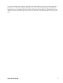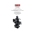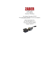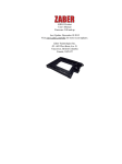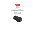
1
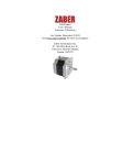
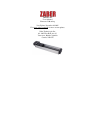
LHM Product
User's Manual
Firmware 5.00 and up
Last Update: December 10 2015
Visit www.zaber.com/wiki for more recent updates.
Zaber Technologies Inc.
#2 - 605 West Kent Ave. N.
Vancouver, British Columbia
Canada, V6P 6T7
Table of Contents
Disclaimer...........................................................................................................................................................1
Precautions.........................................................................................................................................................2
Installation..........................................................................................................................................................3
Physical Installation................................................................................................................................3
Mounting..........................................................................................................................................3
Grounding.........................................................................................................................................3
Maintenance.......................................................................................................................................................4
Operation............................................................................................................................................................5
Pinout for D-sub 15 Connectors (A-series and X-Series controllers and peripherals)...........................5
Alternate Controllers...............................................................................................................................6
Motor......................................................................................................................................................6
Home Sensor Wiring...............................................................................................................................6
Warranty and Repair........................................................................................................................................8
Standard products....................................................................................................................................8
Custom products.....................................................................................................................................8
How to return products...........................................................................................................................8
Email Updates....................................................................................................................................................9
Contact Information........................................................................................................................................10
Comparison - LHM Series.....................................................................................................................12
i
Disclaimer
Zaber’s devices are not intended for use in any critical medical, aviation, or military applications or situations
where a product's use or failure could cause personal injury, death, or damage to property. Zaber disclaims
any and all liability for injury or other damages resulting from the use of our products.
Disclaimer
1
Precautions
Zaber’s motion control devices are precision instruments and must be handled with care. In particular, moving
parts must be treated with care. Avoid axial loads in excess of the rated thrust load, axial and radial impact,
dust and other contaminants and damage to the leadscrew thread. These will reduce the performance of the
device below stated specifications.
Precautions
2
Installation
Physical Installation
Mounting
There are several options available for mounting Zaber stages. Use the mounting holes in the bottom to mount
to a surface or to another stage. You might have to move the carriage to access the bottom mounting holes.
Some stages have mounting holes in the end plates for mounting vertically. Mounting screws are included
with most stages.
Caution: Some stages have threaded through-holes in the top mounting plate of the carriage. Be sure not to
install mounting screws too deep, causing them to interfere with inside parts of the stage.
LHM series stages can be mounted to a standard metric or imperial breadboard with our AP101 adaptor
plates.
Grounding
To prevent damage to the device due to static buildup, the device should be properly grounded.
Failure to ground the unit may result in the unit shutting down unexpectedly or ceasing to communicate with
the computer. This problem can be minimized by not touching the unit during operation. If the unit fails due
to static discharge, unplugging it and plugging it back in or sending a Restore Settings command will usually
fix the problem.
Most Zaber devices are grounded via the shield wire of the data cables. This should normally provide a path to
ground via the computer. For units which are being used without a computer, a ground lead should be
connected to the shield of one of the data cables.
Installation
3
Maintenance
The LHM stages do not need regularly scheduled maintenance, but can be lubricated if performance appears
reduced or a noise is produced by the stage. We recommend Super Lube Bottle Oil with Syncolon (PTFE)
Lubricant (Product number #51004). Super Lube oil can be applied to the lead screw and to the running
surface (silver base) of the stage.
Other lubricants can be used as long as they are compatible with Acetal (Delrin).
Maintenance
4
Operation
The LHM-T3 stages are designed to be controlled with any of Zaber's X-Series or A-Series Stepper Motor
Controllers. Zaber's controllers and peripherals are designed for ease of use when used together. Optimal
settings for each peripheral (such as the default current, speed, acceleration, and limit settings) can be loaded
by setting the peripheralid (T:66) on the controller. The peripheral ID is listed as the ID on the peripheral's
label. A list of IDs is also available on the ID Mapping page. For more information on device operation, refer
to the controller's user manual.
Pinout for D-sub 15 Connectors (A-series and X-Series
controllers and peripherals)
A- or X-series controller (female)
T3 Peripheral (male)
T4 Peripheral (male)
Pin #
1
2
3
4
5
6
7
8
9
10
11
Function
+5V
Encoder Error ****
reserved
Away Sensor ***
Home Sensor
Ground
Motor B1
Motor A1
+5V *
Encoder A *
Encoder B *
Operation
5
12
Encoder Index **
13
Ground *
14
Motor B2
15
Motor A2
* encoder embedded peripherals only
** devices with encoders with index only
*** devices with away sensors only
**** devices with linear or direct-reading encoders only
Alternate Controllers
The device may be controlled by any 2-phase stepper motor controller with home sensor input. Warning:
Operating the unit without correctly wiring up the home sensor can cause permanent damage to the
unit. We do not recommend using your own controller unless you are familiar with how to control a
stepper motor with a hall sensor limit switch. The following information is provided for reference only.
Damage to the actuator or hall sensor due to incorrect wiring is not covered by warranty.
Motor
The LHM stage uses a size 8 stepper motor.
• 0.8 A / Phase
• 5.4 Ω / phase
• 1.5 mH / phase
Home Sensor Wiring
A Hall effect sensor is mounted in the device for use as a home sensor. It is part number A1120LLHLT-T
made by Allegro. Click here for data sheet. Your controller should be configured so the stage stops
immediately (little deceleration) when the home sensor is triggered.
• Wire colour code:
♦ 3.6-24 Vdc input - red
♦ Home signal - yellow
♦ Ground - black
The Hall sensor has an open-collector output. The default output is high impedance when the Hall sensor is
not active. When the sensor detects a magnet, the Hall sensor pulls the output low to ground.
Pinout for D-sub 15 Connectors (A-series and X-Seriescontrollers and peripherals)
6
If you are not using a Zaber controller, ensure that your controller has a pull-up resistor on the output line of
the Hall sensor as shown in the diagram. The bypass capacitor is optional, but may help to eliminate false
triggering in noisy environments. The typical value for the pull-up resistor (RLOAD) is 10k and for the bypass
capacitor is 0.1uF to 1uF. The larger the capacitance, the better the noise filtering but the slower the response
time.
Home Sensor Wiring
7
Warranty and Repair
For Zaber's policies on warranty and repair, please refer to the Ordering Policies
Standard products
Standard products are any part numbers that do not contain the suffix ENG followed by a 4 digit number.
Most, but not all, standard products are listed for sale on our website. All standard Zaber products are backed
by a one-month satisfaction guarantee. If you are not satisfied with your purchase, we will refund your
payment minus any shipping charges. Goods must be in brand new saleable condition with no marks. Zaber
products are guaranteed for one year. During this period Zaber will repair any products with faults due to
manufacturing defects, free of charge.
Custom products
Custom products are any part numbers containing the suffix ENG followed by a 4 digit number. Each of these
products has been designed for a custom application for a particular customer. Custom products are
guaranteed for one year, unless explicitly stated otherwise. During this period Zaber will repair any products
with faults due to manufacturing defects, free of charge.
How to return products
Customers with devices in need of return or repair should contact Zaber to obtain an RMA form which must
be filled out and sent back to us to receive an RMA number. The RMA form contains instructions for packing
and returning the device. The specified RMA number must be included on the shipment to ensure timely
processing.
Warranty and Repair
8
Email Updates
If you would like to receive our periodic email newsletter including product updates and promotions, please
sign up online at www.zaber.com (news section). Newsletters typically include a promotional offer worth at
least $100.
Email Updates
9
Contact Information
Contact Zaber Technologies Inc by any of the following methods:
Phone 1-604-569-3780 (direct)
1-888-276-8033 (toll free in North America)
Fax 1-604-648-8033
Mail #2 - 605 West Kent Ave. N., Vancouver, British Columbia, Canada, V6P 6T7
Web www.zaber.com
Email Please visit our website for up to date email contact information.
The original instructions for this product are available at http://www.zaber.com/wiki/Manuals/LHM.
Contact Information
10
Specification
Microstep Size (Default Resolution)
Integrated Controller
Recommended Controller
Repeatability
Backlash
Maximum Speed
Minimum Speed
Speed Resolution
Encoder Type
Peak Thrust
Maximum Continuous Thrust
Maximum Centered Load
Maximum Cantilever Load
Guide Type
Linear Motion Per Motor Rev
Motor Steps Per Rev
Motor Type
Motor Rated Current
Motor Winding Resistance
Inductance
Motor Connection
Default Resolution
Mechanical Drive System
Limit or Home Sensing
Axes of Motion
LED Indicators
Mounting Interface
Vacuum Compatible
Operating Temperature Range
Contact Information
Value
0.124023437 µm
No
X-MCB1 (48 V) Recommended
< 4 µm
< 30 µm
65 mm/s
0.0012 mm/s
0.0012 mm/s
None
25 N
25 N
50 N
25 N-cm
Plain bearing
1.5875 mm
200
Stepper (2 phase)
600 mA/phase
6.5 ohms/phase
3.5 mH/phase
D-sub 15
1/64 of a step
Lead screw
Magnetic hall sensor
1
No
M3 threaded holes
No
0 to 50 degrees C
Alternate Unit
< 0.000157 "
< 0.001181 "
2.559 "/s
0.00005 "/s
0.00005 "/s
5.6 lb
5.6 lb
11.2 lb
35.4 oz-in
0.062 "
11
RoHS Compliant
CE Compliant
Yes
Yes
Comparison - LHM Series
Part Number
LHM025A-T3
LHM050A-T3
LHM100A-T3
LHM150A-T3
LHM200A-T3
Travel Range
25.4 mm
( 1.000 ")
50.8 mm
( 2.000 ")
101.6 mm
( 4.000 ")
152.4 mm
( 6.000 ")
203.2 mm
( 8.000 ")
Comparison - LHM Series
Accuracy (unidirectional)
50 µm
( 0.001969 ")
75 µm
( 0.002953 ")
125 µm
( 0.004921 ")
175 µm
( 0.006890 ")
225 µm
( 0.008858 ")
Weight
0.30 kg
0.36 kg
0.42 kg
0.46 kg
0.52 kg
12