1
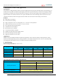
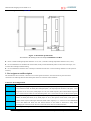
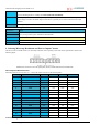
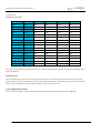
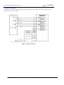
User’s Manual For 2MA2278 High Performance Microstepping Driver Version 1.0 2012 All Rights Reserved Attention: Please read this manual carefully before using the driver! Easy Commercial Global Technology Co., LTD *** Savebase *** --SAVEBASE 2MA2278 Microstepping Driver Manual V1.0 ECG Safety Statement Easy Commercial Global is not liable or responsible for any accidents, injuries, equipment damage, property damage, loss of money or loss of time resulting from improper use of electrical or mechanical or software products sold on this website or other Easy Commercial Global sales resources. Since Easy Commercial Global basically provide OEM machine builders components to build their machines for their own use or third party use it is their responsibility to maintain certify and comply the end user products built base on our components sold on this website or other Easy Commercial Global sales resources. Assembling electrical CNC machine component like power supplies, motors, drivers or other electrical components involve dealing with high voltage like AC alternative current or DC direct current which is extremely dangerous and need high attention & essential experience and knowledge of software, electricity, electro-mechanics & or mechanics. For technical questions please contact us at [email protected] before purchase. 2012 Easy Commercial Global Technology Corporation Limited All Rights Reserved Email: [email protected] Web: http://stores.ebay.co.uk/SAVEBASE 1 --SAVEBASE 2MA2278 Microstepping Driver Manual V1.0 1. Introduction, Features and Applications Introduction The 2MA2278 is a high performance and low noise microstepping driver based on pure-sinusoidal current control technology. It’s suitable for driving 2-phase and 4-phase hybrid stepping motors. By using advanced bipolar constant-current chopping technique, the 2MA2278 can output more torque than other drivers at high speed. The microstep capability allows stepping motors to run at higher smoothness, less vibration and lower noise. Its pure-sinusoidal current control technology allows coil current to be well controlled with relatively small current ripple, therefore smaller motor noise and less motor heating can be achieved. Features High quality, cost-effective Low motor & driver heating Supply voltage from “80V AC to 240V(peak) AC” or “110V DC to 350V(peak) DC” Output current from 0.45A (0.32A AVG) to 7.8A (5.57A AVG) TTL compatible and opto-isolated inputs Automatic idle-current reduction Input frequency up to 400 KHz 16 microstep resolutions selectable Suitable for 2-phase and 4-phase stepping motors DIP switch microstep & current settings Support PUL/DIR & CW/CCW modes Applications Suitable for large and medium automation machines and equipments, such as engraving machines, labeling machines, cutting machines, laser phototypesetting systems, plotting instruments, CNC machines, pick-place devices, and so on. Particularly adapt to the applications desired with low noise, low vibration, high speed and high precision. 2. Specifications Electrical Specifications (Tj = 25℃/77℉) NC-2MA2278 Parameters Min Typical Max Unit Output current 0.45(0.32A avg) - 7.8(5.57A avg) A Supply voltage 80 180 220 VAC Logic signal current 7 10 16 mA Pulse input frequency 0 - 400 KHz Isolation resistance 500 MΩ Operating Environment and other Specifications Cooling Operating Environment Natural Cooling or Forced cooling Environment Avoid dust, oil fog and corrosive gases Ambient Temperature 0 ℃- 50℃ (32℉ - 122℉) Humidity 40%RH - 90%RH Operating Temperature 70℃ (158℉) Max Vibration 5.9m/s2 Max Storage Temperature -20 ℃ - 65℃ (-4℉ - 149℉) Weight Approx. 1000g Email: [email protected] Web: http://stores.ebay.co.uk/SAVEBASE 2 --SAVEBASE 2MA2278 Microstepping Driver Manual V1.0 Mechanical Specifications (unit: mm) Figure 1: Mechanical specifications *Recommend use side mounting for better heat dissipation Elimination of Heat Driver’s reliable working temperature should be <70℃(158℉), and motor working temperature should be <80℃(176℉); It is recommended to use automatic idle-current mode, namely current automatically reduce to 60% when motor stops, so as to reduce driver heating and motor heating; It is recommended to mount the driver vertically to maximize heat sink area. Use forced cooling method to cool the system if necessary. 3. Pin Assignment and Description The 2MA2278 has two connectors, connector P1 for control signals connections, and connector P2 for power and motor connections. The following tables are brief descriptions of the two connectors of the 2MA2278. Connector P1 Configurations Pin Function Details PUL+ Pulse signal: In single pulse (pulse/direction) mode, this input represents pulse signal; 4-5V when PUL-HIGH, 0-0.5V when PUL-LOW. In double pulse mode(pulse/pulse) , this input represents clockwise (CW) pulse,active PUL- at high level or low level (set by inside jumper J1 & J2). For reliable response, pulse width should be longer than 1.5μs. Series connect resistors for current-limiting when+12V or +24V used. The same as DIR and ENA signals. DIR+ DIR signal: In single-pulse mode, this signal has low/high voltage levels, representing two directions of motor rotation; in double-pulse mode (set by inside jumper J1 & J2), this signal is counter-clock (CCW) pulse. For reliable motion response, DIR signal should be ahead of PUL signal by 5μs at least. 4-5V when DIR-HIGH, DIR- 0-0.5V when DIR-LOW. Please note that motion direction is also related to motor-driver wiring match. Exchanging the connection of two wires for a coil to the driver will reverse motion direction. ENA+ Enable signal: This signal is used for enabling/disabling the driver. High level (NPN control signal, PNP and Email: [email protected] Web: http://stores.ebay.co.uk/SAVEBASE 3 --SAVEBASE 2MA2278 Microstepping Driver Manual V1.0 Differential control signals are on the contrary, namely Low level for enabling.) for enabling the driver and low ENA- level for disabling the driver. Usually left UNCONNECTED (ENABLED) Alarm signal positive: READY+ is an opto-coupler output from open-collector circuit, maximum permitted READY+ input voltage is 30VDC; maximum output current 20mA. It generally can be serial connected to PLC input terminal. Alarm signal negative. READY- Connector P2 Configurations Pin Function Details AC AC power supply inputs. Recommend use isolation transformers with theoretical output voltage of 80~180 AC VAC, leaving room for power fluctuation and back-EMF. A+, A- Motor Phase A B+, B- Motor Phase B PE Ground terminal. Recommend connect this port to the ground for better safety. 4. Selecting Microstep Resolution and Driver Output Current This driver uses a 9-bit DIP switch to set microstep resolution, motor operating current and control signal mode as shown in the following figure: Notes: SW5 ON means CW/CCW (pulse/pulse) mode, and SW5 OFF means PUL/DIR mode Microstep Resolution Selection Microstep resolution is set by SW1, 2, 3, 4 of the DIP switch as shown in the following table: Microstep Steps/rev.(for1.8°motor) SW1 SW2 SW3 SW4 2 400 ON ON ON ON 2.5 500 OFF ON ON ON 3 600 ON OFF ON ON 4 800 OFF OFF ON ON 5 1000 ON ON OFF ON 6 1200 OFF ON OFF ON 8 1600 ON OFF OFF ON 10 2000 OFF OFF OFF ON 12 2400 ON ON ON OFF 16 3200 OFF ON ON OFF 20 4000 ON OFF ON OFF 25 5000 OFF OFF ON OFF 30 6000 ON ON OFF OFF 32 6400 OFF ON OFF OFF 40 8000 ON OFF OFF OFF 50 10000 OFF OFF OFF OFF Current Settings Email: [email protected] Web: http://stores.ebay.co.uk/SAVEBASE 4 --SAVEBASE 2MA2278 Microstepping Driver Manual V1.0 The latter four bits (SW6, 7, 8, 9) of the DIP switch are used to set the dynamic current. Select a setting closest to your motor’s required current. Dynamic current setting Peak current(A) RMS(A) SW6 SW7 SW8 SW9 0.45 0.32 OFF OFF OFF OFF 0.63 0.45 OFF OFF OFF ON 1.41 1.00 OFF OFF ON OFF 1.88 1.34 OFF OFF ON ON 2.33 1.66 OFF ON OFF OFF 2.85 2.04 OFF ON OFF ON 3.23 2.31 OFF ON ON OFF 3.75 2.68 OFF ON ON ON 4.26 3.04 ON OFF OFF OFF 4.65 3.32 ON OFF OFF ON 5.18 3.70 ON OFF ON OFF 5.55 3.96 ON OFF ON ON 6.15 4.39 ON ON OFF OFF 6.60 4.71 ON ON OFF ON 7.20 5.14 ON ON ON OFF 7.80 5.57 ON ON ON ON Notes: Due to motor inductance, the actual current in the coil may be smaller than the dynamic current setting, particularly under high speed condition. Standstill Current The NC-2MA2278 has automatic idle-current reduction function. The current automatically be reduced to 60% of the selected dynamic current setting 0.2 second after the last pulse. Theoretically, this will reduce motor heating to 36% (due to P=I2*R) of the original value. If the application needs a different standstill current, please contact with us. Control Signal Mode Setting SW5 is used for this purpose. SW5 ON means CW/CCW (pulse/pulse) mode, and SW5 OFF means PUL/DIR mode. Email: [email protected] Web: http://stores.ebay.co.uk/SAVEBASE 5 --SAVEBASE 2MA2278 Microstepping Driver Manual V1.0 5. Typical Connection A complete stepping system should include stepping motor, stepping driver, power supply and controller (pulse generator). A typical connection is shown as figure 2. Figure 2: Typical connection Email: [email protected] Web: http://stores.ebay.co.uk/SAVEBASE 6