1
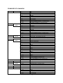
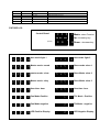
PROMOVER 575
USER MANUAL / OPERATION INSTRUCTION
MLSC, Inc.
P.O. Box 578, Madison, Al 35758
SHIPPING: 8000 MADISON PIKE, MADISON ALA. 35758. PHONE: (256) 461461-8000
www.meteor-global.com
www.meteor-usa.com
1
FAX: (256) 461461-7708
e-mail: [email protected]
PROMOVER 575 DMX-Scanner:
INTRODUCTION
Thank you for having chosen METEOR-KLS PROMOVER 575. You will see you have acquired a
powerful and versatile device. It has been designed to be very flexible and user friendly, without
compromising effectiveness or professionalism.
Unpack your PROMOVER 575.
Before you initial start-up, please make sure that there is no damage caused by transportation.
Should there be any questions or problems, consult your dealer and do NOT use the device.
SAFETY INSTRUCTIONS: (notes written in this user manual.)
CAUTION! Be careful with your operations. With a dangerous voltage you can suffer a
dangerous electric shock when touching the wires.
This PROMOVER
PROMOVER 575 has left our premises in absolutely perfect condition. In order to maintain this
condition and to ensure a safe operation, it is absolutely necessary for the user to follow the
safety instructions and follow all the warnings.
Important:
Damages caused by the disregard of this user manual are not subject to warranty. The
dealer will not accept liability for any resulting defects or problems.
CAUTION! Keep this device away from rain and moisture!
Unplug mains lead before opening the housing.
SAFETY INSTRUCTIONS
For your own safety, please read this user manual carefully before your initial start-up.
Every person involved with the installation, operation and maintenance of this device has
to:
- be qualified
- follow the instructions of this manual
- consider this manual to be part of the total product
- keep this manual for the entire service life of the product
- pass this manual on to future owners or users of this product
- include every supplementary update with the original manual
If the device has been exposed to drastic temperature fluctuation (e.g. after
transportation). Do NOT switch it on immediately. Allow fixture to reach normal room
temperature. By not doing so, the water condensation might damage your device and
cause severe damage to lamp and circuit boards.
Leave the device switched off until it has reached room temperature.
This device falls under protection-Class I.
The power plug must only be plugged into a protection Class I outlet.
Never let the power-cord come into contact with other cables!
Handle the power-cord and all connections to the mains with particular caution.
Make sure that the available voltage is not higher than stated on the rear panel.
Make sure that the power-cord is never crimped or damaged by sharp edges.
Check the device and the power-cord from time to time.
Always disconnect from the mains, when the device is not in use or before cleaning it.
Only handle the power-cord by the plug.
Never pull out the plug by tugging the power-cord.
2
-
-
During the initial start-up some smoke or smell may arise. This is a normal process and
does not necessarily mean that the device is defective.
Caution: During the operation, the housing becomes very hot.
Do not switch the device On and Off in short intervals as this would reduce the lamp's life.
Keep away from children and non-qualified users.
OPERATING DETERMINATIONS
This device is a lighting effect for creating decorative entertainment lighting effects.
This product is only allowed to be operated with an alternating voltage of 120 V,60 Hz and
was designed for indoor use only.
This device is designed for professional use on stages, in discotheques, theatres etc.
Lighting effects are not designed for permanent operation.
Consistent operation breaks will ensure that the device will serve you for a long time
without defects.
Do not shake the device. Avoid brute force when installing or operating the device.
When choosing the installation-spot, please make sure that the device is not exposed to
extreme heat, moisture or dust.
There should not be any cables lying around. You endanger your own and the safety of
others!
The symbol - - -“m” determines the minimum distance from lighted objects.
The minimum distance between light-output and the illuminated surface must be more than
0.5 meters.
This device is only allowed for suspended installation via the mounting bracket. In order to
safeguard sufficient ventilation, leave 50 cm of free space around the device.
Make sure that the area below the installation place is blocked off when rigging, derigging
or servicing the fixture.
Always secure the fixture with an appropriate safety-rope and proper rigging hardware
designed to hold more than 10 times the weight of the fixture (proper industry standard).
Never look directly into the light source, as sensitive persons may suffer an epileptic shock
The maximum ambient temperature t = 45° C must never be exceeded.
Operate the device only after having become familiar with its functions.
Do not permit operation by persons not qualified for operating the device. Most damages
are the result of unprofessional operation!
Please use the original packaging if the device is to be transported.
Please consider that unauthorized modifications on the device are forbidden due to safety
reasons and will void any warranty
Never remove the serial barcode from the device, as this would make the warranty void.
If this device will be operated in any way different to the one described in this manual, the
product may suffer damages and the warranty becomes void. Furthermore, any other
operation may lead to dangers like short-circuit, burns, electric shock and lamp explosion,
Lamps and fuse replacements are not covered under warranty.
3
USER MANUAL:
ProMover 575 DMX-Scanner - Yoke Fixture
Keep this manual for future needs! Put it in a place that you can access it if needed.
Table of contents:
INTRODUCTION: ………………………………….……………
SAFETY INSTRUCTIONS: ……………………………
OPERATING DETERMINATIONS: ………………….
USER MANUAL INSTRUCTIONS: ………………….
DESCRIPTION OF THE DEVICE: ……………………………
FEATURES: …………………………………………….
2
2
3
4
5
OVERVIEW
INSTALLATION : ……………………………………………….
Installing/Replacing the lamp: ………………………….
Lamp adjustment: ………………………………………..
Overhead Rigging:………………………………………..
Master/Slave operation : ………………………………...
DMX-512 connection / connection between Fixtures: ..
Connection with the mains: ……………………………..
5
5
6
6
7
7
7
OPERATION ............................................................………
Stand Alone operation................................................
DMX-controlled operation ..............................…........
Addressing ..................................................................
DMX-Protocol.............................................................………
ProMover 575 – channel features: …………………….
Setting DMX Channel / Stand-alone LCD: ……………
8
8
8
9
10
10
CLEANING AND MAINTENANCE: .......................................
Replacing the fuse .......................................................
11
12
TECHNICAL SPECIFICATIONS:
Power supply: 115 V AC, 60 Hz ~ 500 W 6
Power consumption: 800w
DMX-control-channels: 14 channels
DMX-512-connection: 3-pin XLR
Sound-control: via built-in microphone
Strobe Flash-rate: (1-10 flashes/sec.) via shutter
Number of colors: 16 dichroic + white +RAINBOW effect
Number of gobos: 14 rotating gobos and open + rainbow scrolling
Dimensions: 16L x 13w x 20h (500 x 485 x 615 mm)
Weight: 62 lbs. (24kg). Boxed weight: 71lbs
Maximum ambient temperature (ta): 45° C
Maximum housing temperature (tB) (steady state): 60° C
Min. distance from flammable surfaces: 0.5 m
Min. distance to lighted object: 0.5 m
Fuse: 10 amp
Fitting lamp: HMI 575
4
DESCRIPTION OF THE DEVICE:
Features:
•
•
•
•
•
•
•
•
•
•
•
•
•
•
Innovative Professional scanner with rotating gobos
16 different, dichroic color filters and white
Rainbow-effect with adjustable speed in both directions
Gobowheel with 14 rotating gobos, open and blackout
Strobe-effect with adjustable speed (1-10 flashes/sec.) via shutter
DMX-controlled operation or stand alone operation with Master/Slavefunction
Sound-controlled via built-in microphone
Fuzzy-Sound-Control: program continues automatically during periods
without music or bass-beat
Control-Board with 4-digit LCD display
Digital DMX focus
For HMI 575
Actual Lamp Hours – User time.
DMX-control via every standard DMX-controller
14 DMX-control channels required
DANGER TO LIFE:
Only install the lamp with the device switched off. And not plugged into power
Always unplug power from mains before attempting any service.
For the installation, you need one HMI 575. Do not touch glass part of lamp.
The lamp must only be changed when wearing appropriate protective clothing (protection
glasses, protection gloves, helmet with sight, leather apron).
INSTALLATION
Installing/Replacing the lamp Procedure:
CAUTION!
The lamp has to be replaced when it is damaged or deformed due to the heat!
The lamp life given by the manufacturer must never be exceeded. This is why you need to
take notes on the operational time of the lamp and replace the lamp in time.
Keep exchanged lamp in a protective container and remove accordingly.
During the operation, the lamp reaches temperatures of up to 600° C.
Before replacing the lamp, unplug mains lead and let the lamp cool down (approx. 10
minutes).
During the installation do not touch the glass-bulbs barehanded!
Please follow the lamp manufacturer's notes!
Do not install lamps with a higher wattage! Lamps with a higher wattage generate
temperatures the device was not designed for.
Damages caused by non-observance are not subject to warranty.
Step 1: Unscrew the 4 Phillips screws on back plate. Unscrew 4 Phillip head screws that hold
lamp housing system to fixture and carefully remove it from the housing.
Step 2: If replacing the lamp, remove the old lamp from the lamp holder.
Step 3: Insert the lamp into the lamp holder. Make sure lamp is properly secured in brass fitting.
Step 4: Replace the lamp system in the housing and tighten the fixation screws.
Step 5: Adjust the lamp as described under lamp adjustment.
Do not operate this device with opened cover!
5
Lamp adjustment
The lamp holder is aligned at the factory. Due to differences between lamps, fine
adjustment may improve light performance.
Strike the lamp, open the shutter, and set the dimmer intensity to 100 % and focus the light
on a flat surface (wall).
Center the hot-spot (the brightest part of the beam) using the 3 adjustment screws "A, B,
C". Turn one screw at a time to drag the hot-spot diagonally across the projected image. If
you cannot detect a hotspot, adjust the lamp until the light is even.
To reduce a hot-spot, pull the lamp in by turning all three screws "A, B, C" clockwise 1/4turn at a time until the light is evenly distributed. If the light is brighter around the edge than
it is in the center, or if light output is low, the lamp is too far back in the reflector. "Push" the
lamp out by turning the screws "A, B, C" counterclockwise 1/4-turn at a time the light is
bright and evenly distributed.
Overhead Rigging if the main attachment fails as a secondary back-up
DANGER TO LIFE!
Please consider the DIN 15560 and the respective national norms during the installation!
An authorized dealer must only carry out the installation!
The installation of the device has to be built and constructed in a way that it can hold 10
times the weight for 1 hour without any harming deformation.
The installation must always be secured with a secondary safety attachment, e.g. an
appropriate catch net.
This secondary safety attachment must be constructed in a way that no part of the
installation can fall down
When rigging or derigging or servicing the device staying in the area below the installation
place, on bridges, under high working places and other endangered areas is forbidden.
The operator has to make sure that safety-relating and machine-technical installations are
approved by an expert before taking into operation for the first time and after changes
before taking into operation another
The operator has to make sure that safety-relating and machine-technical installations are
approved by an expert after every four year in the course of an acceptance test.
The operator has to make sure that a skilled person approves safety-relating and machinetechnical installations once a year.
Procedure:
The device should be installed outside areas where persons may walk by or be seated.
IMPORTANT!
OVERHEAD RIGGING REQUIRES EXTENSIVE EXPERIENCE, including (but not limited
to) calculating working load limits, installation material being used, and periodic safety
inspection of all installation material and the device. If you lack these qualifications, do not
attempt the installation yourself, but instead use a professional structural rigger. Improper
installation can result in bodily injury and or damage to property.
The device has to be installed out of the reach of people.
If the device shall be lowered from the ceiling or high joists, professional trussing systems
have to be used.
The device must never be fixed swinging freely in the room.
Caution: Devices in hanging installations may cause severe injuries if not properly
mounted and secured correctly with appropriate back-up “failsafe rigging”.
6
If you have doubts concerning the safety of a possible installation, DO NOT install the
device.
Before rigging make sure that the installation area can hold a minimum point load of 10
times the device's weight.
Master/Slave-operation
The master/slave-operation enables that several devices can be synchronized and
controlled by one Master device unit
On the rear panel of the PROMOVER 575 you can find an XLR-jack (DMX Out) and an XLRplug (DMX In), which can be used for connecting several devices.
Choose the device that is to control the effects. This device then works as master-device
and controls all other slave-devices, which are to be connected to the master-device via a
balanced microphone lead.
Connect the DMX OUT-jack with the DMX IN-plug of the next device.
Set the desired Master-mode for the master-device.
Set the respective Slave-mode for all slave-devices.
-
-
-
-
DANGER OF FIRE!
When installing the device, make sure there is no highly-inflammable material (decoration
articles, etc.) within a distance of min. 0.5 m.
Mount the device to your trussing system using an appropriate clamp. For overhead use,
always install a safety-rope / chain that can hold at least 12 times the weight of the fixture.
You must only use safety-ropes with quick link with screw cap. Pull the safety-rope through
the attachment eyelet and over the trussing system or a safe fixation spot. Insert the end in
the quick link and tighten the safety screw.
The maximum drop distance must never exceed 20 cm.
A safety rope / chain which already held the strain of a crash or which is defective must not
be used again.
Adjust the desired inclination-angle via the mounting-bracket and tighten the fixation
screws.
DANGER TO LIFE!
Before taking into operation for the first time, the installation has to be approved by an
expert.
Connection with the mains
Connect the device to the mains with the enclosed power supply cable.
DMX-512 connection / connection between fixtures
The wires must not come into contact with each other, otherwise the fixtures will not work
at all, or will not work properly.
Only use a stereo shielded cable and 3-pin XLR-plugs and connectors in order to connect
the controller with the fixture or one fixture with another.
Occupation of the XLR-connection:
-If you are using controllers with this occupation, you can connect the DMX-output of the
controller directly with the DMX-input of the first fixture in the DMX-chain. If you wish to
connect DMX-controllers with other XLR-outputs (5-pin), you need to use adapter-cables.
Building a serial DMX-chain:
Connect the DMX-output of the first fixture in the DMX-chain with the DMX-input of the
next fixture. Always connect one output with the input of the next fixture until all fixtures are
connected.
7
Caution:
At the last fixture, the DMX-cable has to be terminated with a terminator. Solder a 120-ohm
resistor between Signal (-) and Signal (+) into a 3-pin XLR-plug and plug it in the DMXoutput of the last fixture.
OPERATION:
After you connected the fixture to the mains, the PROMOVER 575 starts running / resetting.
During the Reset, the motors are trimmed and the device is ready for use afterwards.
Note: You will here “clicking” noise. That is each of the motors stepping through sequence
to find each “0” starting position. This is normal.
Stand Alone operation:
In the Stand Alone mode, the PROMOVER 575 can be used without controller. You can do
without a controller as the PROMOVER 575 features a built-in microphone, which provides
automatic sound control.
Disconnect the PROMOVER 575 from the controller and select "Master Mode: Soundcontrol".
Master/Slave-operation
Connect the master and slave-devices and adjust the settings as described above.
Please note: If you wish to change from one operating mode into another, you have to
unplug the PROMOVER 575 from the mains and plug it again.
DMX-controlled operation:
You can control the projectors individually via your DMX-controller. Every DMX-channel
has a different occupation with different features. In order to call up the different features,
you first have to open the shutter (control channel 9, DMX-value 132-139 or 250-255) or
set the dimmer to the desired intensity (control channel 6, DMX-value 6-128).
Addressing
The Control Board on the front side of the base allows you to assign the DMX fixture
address, which is defined as the first channel from which the PROMOVER 575 will respond
to the controller.
If you set, for example, the base address to channel 1, the PROMOVER 575 will use
channels 1 to 14 for control. Next available DMX value would be set for 15.
Please, be sure that you don't have any overlapping channels in order to control each
PROMOVER 575 correctly and independently from any other fixture on the DMX data link.
If two, three or more PROMOVER 575 are addressed similarly, they will work similarly.
Before you attempt to operate this unit – make sure you have no unanswered questions.
8
PROMOVER 575 CHANNELS
CH. 1
CH. 2
COLOR
ROTATING
GOBO
0-7
8 - 15
16 - 23
WHITE
PINK
YELLOW
24 - 31
32 - 39
40 - 47
BLUE
ORANGE
GREEN
48 - 55
56 - 63
64 - 127
128 - 191
192 - 255
LIGHT PINK
LIGHT PURPLE
GRADUAL COLOR CHANGE
POSITIVE RAINBOW EFFECT w / increasing speed
REGRESSIVE RAINBOW w / decreasing speed
16 - 31
38732 CIRCLE
SPIRAL
32 - 47
48 - 63
64 - 79
80 - 95
96 - 111
112 - 127
128 - 191
192 - 255
BREAKOUT
HAZARD
DESIGN
TRIANGLE
FIRE
SUN
POSITIVE RAINBOW EFFECT w increasing speed
REGRESSIVE RAINBOW w / decreasing speed
CH. 3
GOBO
ROTATE
0 - 15
16 - 135
136 - 255
STOP
SPEED GOBO - CLOCKWISE (right to left)
SPEED GOBO - counter - CLOCKWISE (left to right)
CH. 4
STATIC
GOBO
0–7
8 - 15
16 -23
RING
HAND
OVERLAY TRIANGLES
24 - 31
32 - 39
40 - 47
48 - 55
56 - 63
64 - 71
72 - 79
80 - 87
88 - 95
96 - 103
104 - 111
112 - 119
120 -127
128 - 191
PROPELLOR
SLANTED STAR
MORAY
RADIOACTIVE
SINGLE SPIRAL
WHITE
GOBO 1
GOBO 2
GOBO 3
GOBO 4
GOBO 5
GOBO 6
GOBO 7
POSITIVE RAINBOW (clockwise scroll)
192 - 255
NEGATIVE RAINBOW (counter clockwise scroll)
CH. 5
PAN
0 - 255
360deg, 8 bit
CH. 6
TILT
0 - 255
270deg, 8 bit
CH. 7
EFFECT
(prism)
0 -15
116 - 239
240 - 255
WHITE
PRISM ROTATION - Decreasing speed
STOP, STATIC PRISM
MOTORIZED FOCUS - zoom in / zoom out
CH. 8
FOCUS
0 - 255
CH.9
SHUTTER
0 - 15
SHUTTER CLOSED
16 - 128
129 - 133
134 - 243
244 - 249
250 - 255
DIMMER CONTROL
WHITE
STROBE EFFECT- increasing
RESET (after 5 seconds)
SHUTTER OPEN
9
CH 10
IRIS
CH 11
LAMP
0 - 255
IRIS OPEN TO CLOSE
0-5
200 - 210
LAMP ON (Delay after 10 minutes)
LAMP OFF (after 5 second)
CH.12
SPEED
0 - 255
X / Y CONTROLLABLE SPEED
CH.13
PAN-16
0 - 255
MOTOR SPEED PAN - 16 bit
CH.14
TILT - 16
0 - 255
MOTOR SPEED - TILT - 16 bit
FIXTURE LCD:
Control Board
8 8 8
8 Mode: select Function
up dn md
(buttons)
0
Up: increasing key
0 Down - decrease key
0
0 01
d
dmx mode:light 1
0 13
d
dmx mode: light 2
n 1n
n
Master mode: sound
5 15
5
Slave mode: slave 1
n 2n
n
master mode - slow
5 25
5
Slave Mode: slave 2
n 3n
n
Master mode - stby
5 35
5
Slave Mode: slave 3
0 0 0 HH
User time: hour
5 4 5 H5
.
1
P
Pan Mode-Positive
1
t
Tilt Mode - Positive
.
2
P
Pan Mode-negative
2
t
Tilt Mode - negative
.
1
L
LED Positive Display
2
L
LED Negative Display
.
10
User time: hour
1-
Pan Mode Positive: Normal operation: When you press the Pan1 and Pan2, their starting
off point of Pan will be different.
2Pan Mode Negative: (mirror image); the Starting -off point of Pan1 = the end-point of Pan2
the Jumping-off point of Pan2 = the end-point of Pan1.
3Tilt Mode Positive: Normal operation: When you press the Tilt 1 and Tilt 2, their starting
off point of Tilt will be same.(seldom ever used)
4Tilt Mode Negative: Also same as Pan. (seldom ever used)
5LED Positive Display: When leaving on floor mounted or on test bench (as shown)
6LED Negative Display When you reverse the unit, if you make "LED Negative Display",
then it's more convenient to see the display when upside down and mounted.
For address setting,
Press the Mode-button until the display shows "d" and set the desired base address via
the Up / Down-buttons.
Controlling:
After having addressed all PROMOVER 575 you may now start operating these via your
lighting controller.
Note: After switching on, the PROMOVER 575 will automatically detect whether DMX 512
data is received or not. If the data is received, the control LED flashes. If there is no data
received at the DMX-input, the control LED lights up permanently.
This situation can occur if:
The 3 PIN XLR plug (cable with DMX signal from controller) is not connected with the input
of the PROMOVER 575 or having a bad connecting cable
The controller is switched off or defective, if the cable or connector is defective or the
signal wires are swapped / reversed in the input connector.
Note: It's necessary to insert the XLR termination plug (with 120 Ohm) in the last lighting in
the link in order to ensure proper transmission on the DMX data link.
CLEANING AND MAINTENANCE
The operator has to make sure that safety-relating and machine-technical installations are
Inspected by an expert after every four years in the course of an acceptance test.
The operator has to make sure that safety-relating and machine-technical installations are
inspected by a skilled person once a year.
The following points have to be considered during the inspection:
1) All screws used for installing the devices or parts of the device have to be tightly
connected and must not be corroded.
2) There must not be any deformations on housings, fixations and installation spots
(ceiling, suspension, trussing).
3) Mechanically moved parts like axles, eyes and others must not show any traces of
wearing (e.g. material abrading or damages) and must not rotate with unbalances.
4) The electric power supply cables must not show any damages, material fatigue (e.g.
porous cables) or sediments. Further instructions depending on the installation spot and
usage have to be adhered to by a skilled installer and any safety problems have to be
removed.
Disconnect from mains before starting maintenance operation!
11
-
We recommend a frequent cleaning of the device. Please use a moist, lint-free
cloth.
Never use alcohol or solvents!
The lens has to be replaced when it is obviously damaged, so that its function is
impaired, e. g. due to cracks or deep scratches!
The objective lens will require weekly cleaning as smoke-fluid tends to building up
residues, reducing the light-output very quickly.
The cooling-fans should be cleaned monthly.
The gobos may be cleaned with a soft brush.
The interior of the fixture should be cleaned at least annually using a vacuum
cleaner or an air-jet.
The dichroic color filters, the gobo-wheel and the internal lenses should be cleaned
monthly.
To ensure a proper function of the gobo-wheel, we recommend lubrication in sixmonth intervals.
Carefully placed quantity of oil must not be excessive in order to avoid that oil runs
out when the gobo-wheel rotates.
There are no serviceable parts inside the device.
Maintenance and service operations are only to be carried out by authorized
dealers.
Please refer to the instructions under "Installing/Replacing the lamp".
Replacing the fuse
If the fine-wire fuse of the device fuses, only replace the fuse by a fuse of same type and
rating.
Before replacing the fuse, always unplug mains lead / power cable
Procedure:
Step 1:
Open the Fuse-holder on the rear panel with a slotted screwdriver (below power)
Step 2:
Remove the old fuse from the fuse holder.
Step 3:
Install the new fuse in the fuse holder.
Step 4:
Replace the fuse holder in the housing.
Should you need any spare parts, please use genuine parts.
If the power supply cable of this device becomes damaged, it has to be replaced by
a special power supply cable available at your dealer.
Should you have further questions, please contact your dealer.
Please note: All information is subject to change without prior notice.
MLSC, Inc.
P.O. Box 578, Madison, Al 35758
SHIPPING: 8000 MADISON PIKE, MADISON ALA. 35758. PHONE: (256) 461461-8000
www.meteor-global.com
www.meteor-usa.com
12
FAX: (256) 461461-7708
e-mail: [email protected]