1
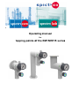
4 Opera ating manua m al for tapping po oints o of the EM15//EE15 series s Operating manual EM15/EE15 series Table of Contents Table of Contents ........................................................................................................ 2 1. Introduction ........................................................................................................... 3 1.1 General............................................................................................................ 3 1.2 Description of the EM15 and EE15 tapping points series ............................... 3 1.3 Intended use.................................................................................................... 4 1.4 Personnel requirements .................................................................................. 4 2. For your safety ..................................................................................................... 5 2.1 Symbols used .................................................................................................. 5 2.2 Essential safety information ............................................................................ 5 2.3 Safety features ................................................................................................ 6 3. Description ........................................................................................................... 7 3.1 Design of the EM15 and EE15 series tapping points ...................................... 7 3.2 Structural and functional description ............................................................... 8 3.3 Technical data ................................................................................................. 9 3.4 Connection options.......................................................................................... 9 3.5 Labelling .......................................................................................................... 9 4. Assembly and operation ..................................................................................... 10 4.1 Installation ..................................................................................................... 10 4.2 Putting the tapping point into operation ......................................................... 20 4.3 Taking the unit out of service ......................................................................... 21 5. Faults .................................................................................................................. 21 6. Maintenance, cleaning and repairs..................................................................... 22 6.1 Regular maintenance work and visual inspections........................................ 22 6.2 Regular cleaning ........................................................................................... 22 6.3 Repair information ......................................................................................... 22 6.4 Returns .......................................................................................................... 22 2 GES_EM+EE_15_0915.DOCX Operating manual EM15/EE15 series 1. 1.1 Introduction General Validity This user manual applies to EM15 and EE15 tapping points. Manufacturer Spectron Gas Control Systems GmbH Fritz-Klatte-Straße 8 D-65933 Frankfurt Germany Telephone: +49 69 38016-0 Fax: +49 69 38016-200 E-mail: [email protected] Internet: www.spectron.de Publication date September 2015 Retention and completeness This user manual is a component of the EM15 and EE15 tapping points and must be kept in a location visible for the authorised group of persons at all times. At no time may chapters be removed from this user manual. A missing user manual or missing pages – particularly the "For your safety" chapter – must be replaced immediately. Copyright This user manual contains copyrighted information. It must not be photocopied, reproduced, translated or copied onto data carriers, either in full or in part, without prior authorisation. All rights reserved. Updates This user manual is not subject to updates by Spectron Gas Control Systems GmbH. Changes to this user manual may take place without prior notification notification. 1.2 Description of the EM15 and EE15 tapping points series The tapping points of the EM15 and EE15 series are specifically designed for integration in laboratory furniture. They provide high purity and special gasses for the optimal supply of laboratory devices. The main task of the tapping points is to reduce the respective inlet pressure to the required outlet pressure in the specific laboratory applications. The gas supply can be interrupted or released to the laboratory appliances using the shut-off valve on the pressure regulator or the optionally configurable service valve. 3 GES_EM+EE_15_0915.DOCX Operating manual EM15/EE15 series 1. 1.3 Introduction Intended use Intended use The EM15 tapping points are intended for use with non-corrosive gases up to quality 6.0. The EE15 tapping points are additionally intended for use with corrosive gases up to quality 6.0. The permitted gases and pressure areas for the tapping points are specified on the product label and the gas type label. Tapping points are used in most cases as a second pressure control and shut off unit following a pressure control panel at the end points of a piping system. They are used to additionally reduce the already relatively constant pipeline pressure downstream of the pressure control panel to a highly constant outlet pressure towards the application. Tapping points may be used in an ATEX area because they do not have a potential ignition source of their own (ignition hazard assessment in accordance with DIN EN 13463-1). Foreseeable misuse The following operating conditions are deemed to constitute misuse: Operation with gases that are not specified on the product label Use with gases in their liquid condition Operation in an environment that has a higher than normal amount of dust particles or humidity as well as operation in an environment with salty, oily or acidic atmospheres Operation in environments outside a temperature range of -20 °C to +60 °C Operation in environments that can cause vibrations on or impacts to the fitting Failure to comply with the locally applicable legal regulations and provisions The use of oil and grease when handling the fitting Failure to follow this manual Failure to carry out inspection and maintenance work Failure to heed the information on the product label and in the product data sheet Pressurisation counter to the normal direction of flow 1.4 Personnel requirements Definition of an authorised person A person qualifies as an authorised person if they have received technical training and have received technical instructions on the entire system and the associated dangers – gas cylinder – type of gas – gas cylinder valve – pressure regulator and have also successfully completed training in the field of "Supply of pressurised gases". Tasks of the operating personnel The operating personnel must identify faults or irregularities and remove where possible and permissible. Requirements placed on operating personnel To be able to fulfil the tasks, the operating personnel must meet the following requirements: 4 The operating personnel must have received instruction in the operation of the tapping point from an authorised person and must have read and understood this operating manual in its entirety. GES_EM+EE_15_0915.DOCX Opera ating ma anual EM15 5/EE15 se eries 2. For yourr safety 2.1 1 Symbols used Note! IImportantt! Warnin ng! Dange er! ANGER! DA This symbol warns w that th here is a "ris sk of fatal injury" or a health hazzard nel. for the personn 2 2.2 Essential safety in nformation n Notte! The e following safety s notes s are intend ded to be us sed as an addition to thhe already applicable a national accide ent prevention regulatio ons and law ws. Existing accident pprevention re egulations and a law ws must be complied c with at all tim mes. Va arious laws, regulationss, rules and directives a are authorittative when handling coompressed gasses. Th hese must b be observed d depending g on each tyype of gas. Th he following list lays no o claim to be e exhaustive e; it merely represents a selectionn of the mos st importantt sections: EU Directive 2009/10 04/EC (Worrk Equipmen nt Directive) 2/EC (ATEX X 137) EU Directive 1999/92 EU Directive 98/24/E EC (risks related to che emical agents at work) ulations on industrial sa afety and health) publications TRBS (tecchnical regu German te echnical rules for haza ardous subsstances (TR RGS) TRAS (tecchnical regu ulations on plant safetyy) publicatio ons BGV A1 Principless of preventtion BGR 104 Explosion n protection rules zards cause ed by electro ostatic charrges BGR 132 Avoiding ignition haz BGR 500 ding, cutting g and relate ed working procedures p 2.26 Weld BGR 500 2.31 Work on gas lin nes BGR 500 eration of ox xygen syste ms 2.32 Ope BGR 500 2.33 Ope eration of sy ystems for th he handling g of gases eaflet M034 BG RCI le EIGA docu uments Safety datta sheets fo or the gases s used 5 GES_EM+E EE_15_0915.D DOCX Operating manual EM15/EE15 series 2. 2.3 For your safety Safety features Caution! The EM15 and EE15 tapping points do not have a relief valve. To protect the downstream fittings, pressure vessels and pipes against overpressure due to a possible failure of the tapping point pressure regulator, a separate safety device that complies with any relevant regulations must be installed. Possible hazard Prevention measures Keep all parts that come into contact with oxygen Danger! If oxygen comes into contact with oil or grease, there is free from oil and grease. a risk of fire due to a chemical reaction. Smoking and naked flames are strictly prohibited Danger! Gas escaping into the ambient air can ignite; there is a near gas supply equipment. risk of fire and explosion. Danger! The tapping point may be damaged by unauthorised changes or alterations and may no longer work as intended. There is a risk of the system malfunctioning, catching fire or getting damaged. No changes or alterations may be carried out without written permission from technically authorised manufacturer personnel. Danger! If tapping points are used that are not suitable for the relevant gas and pressure range, there is a risk of a fire or explosion occurring as a result of a chemical reaction. The tapping point must be suitable for the relevant gas and the pressure ranges involved. Only use for the gases indicated on the device. If there are no gas types specified on the tapping point, you have to ask the manufacturer which gases it can be used with. On no account must the tapping point be put into operation without this information. Danger! If the tapping point is used outside the specified ambient temperature range, there is a risk of the system malfunctioning, catching fire or getting damaged. Do not use in ambient temperatures below −30 °C and above +60 °C. Danger! Improper handling and impermissible use can lead to danger for the user, other persons as well as damage to the device. Use and handle the tapping point only as described in this operating manual. If dirt particles get into the pressure regulator of the tapping point, this can damage it or cause it to malfunction. It must be ensured that no dirt particles of any kind can get into the pressure regulator. 6 GES_EM+EE_15_0915.DOCX Operating manual EM15/EE15 series 3. 3.1 Description Design of the EM15 and EE15 series tapping points 5 4 7 6 2 1 8 9 3 10 11 Elements of the tapping point Item Designation Function 1 Rear wall connection (RWA) Used as the connection point for the gas supply system 2 Integrated shut-off valve Seals the piping system as long as no tapping point is installed and is used as the primary pressure shut-off valve for installed tapping points 3 Fastening screws Self-tapping screws for fastening the RWA to the furniture wall 4 Pressure regulator Diminishes the inlet pressure P1 to the adjusted outlet pressure P2 5 Union nut Fastens the tapping points to the RWA 6 Rotary lever Used to actuate the shut-off valve 7 Open/closed display Shows the position of the shut-off valve 8 Hand wheel Used for setting the outlet pressure 9 Pressure gauge Indicates the current outlet pressure 10 Gas type label Shows the type of gas the tapping points may be used for 11 Gas outlet The following consumer unit can be connected to this component. As depicted in the image, a service gas valve can optionally be installed here. It is used to shut off the outlet pressure regulator. In all cases, the connection thread is a female ¼”-NPT. 7 GES_EM+EE_15_0915.DOCX Operating manual EM15/EE15 series 3. 3.2 Description Structural and functional description The EM15 and EE15 tapping points are specifically designed for use with laboratory furniture. The design of the fittings consists of a connecting part, called the rear wall connection, which supports various methods of installation: panel-mounted, surface-mounted, wall-mounted, ceiling- or column-mounted. After the installation of the rear wall connection with an integrated shut-off valve, the main component, the pressure regulator, is screwed on. Only a metallic sealing is utilised, without additional sealing elements. The pressure regulator has different outlet and connection variations downstream. As an option, a control / shut-off valve can be installed in the outlet of the pressure regulator. There is also the option of screwing a control / shut-off valve or a wall outlet (without pressure regulator) directly onto the rear wall connection. The rear wall connection contains a non-return valve that makes it possible to uninstall a tapping point from a rear wall connection at any time without having to vent the pipe arranged upstream beforehand. This also makes it possible to include points in the structure at which a tapping point can be connected later. The entire gas supply system can continue to operate uninterrupted while the tapping point is connected at a later time. The outlet pressure can be adapted to new requirements by replacing the tapping point. The pressure regulator's shut-off valve is actuated using what is called the rotary lever. Depending on the position, a colour mark on the pressure regulator is either red to indicate the closed position or green to indicate the open position of the shut-off valve. Open position Closed position The pressure regulator's pressure setting is controlled using the hand wheel, which encloses the pressure gauge. Turning the hand wheel clockwise increases the pressure. Turning the hand wheel counterclockwise decreases the pressure. 8 GES_EM+EE_15_0915.DOCX Operating manual EM15/EE15 series 3. 3.3 Description Technical data 3.4 Note! The technical data can be taken from the Spectron data sheet for the relevant product. If this is not available, you can view and download it at www.spectron.de. The maximum inlet and outlet pressures and the gas type are indicated on the product label. Connection options Inlet pressure connections on the RWA: AW/AE model 1/4"-NPT female thread or 6 mm pipe end for clamping ring screw connections EP/EF model 1/4"-NPT male thread DC/ES model 1/4"-NPT female thread SC model 6 mm pipe end for clamping ring screw connections 3.5 Outlet pressure connection: 1/4"-NPT female thread or 6 mm pipe end for clamping screw connections or as soldering/welding end Labelling Labelling example Gas type identification with labels in accordance with EN 13792 EM15-AW-10-0-V-DL P1: 40 bar P2: 10 bar 2015.09 (manufacturing date) 9 GES_EM+EE_15_0915.DOCX Operating manual EM15/EE15 series 4. Assembly and operation 4.1 Installation 4.1.1 Rear wall connection assembly Rear wall connection with 6 mm pipe end and cover plate Ø Ø Arrange the furniture wall as depicted in the drilling pattern drawing Screw in self-tapping screws and fasten the rear wall connection to the furniture wall Snap on covering caps and attach the gas type label Ø Rear wall connections with M24x1 and female 1/4NPT Arrange the furniture wall as depicted in the drilling pattern drawing Screw on M24x1 nuts and fasten the rear wall connection to the furniture wall Snap on covering caps and attach the gas type label Rear wall connection with adapter plate using the drilling pattern of the previous series Ø Ø 10 Arrange the furniture wall as depicted in the drilling pattern drawing Fasten the adapter plate to the furniture wall using the supplied self-tapping screws Fasten the rear wall connection to the adapter plate using the supplied M5x8 countersunk screws Snap on covering caps and attach the gas type label GES_EM+EE_15_0915.DOCX Operating manual EM15/EE15 series 4. Assembly and operation 4.1.2 Assembling and screwing together the rear wall connection and tapping point Special attention is needed when assembling the rear wall connection and the actual tapping point (this equally applies to the column-mounted and the ceiling connection). Both connecting parts have a hexagonal geometry that serves to aid positioning and acts as an anti-twist lock. It is very important that both hexagonal geometries are threaded in the correct position when manually screwing on the SW20 union nut. While doing this, no force may be applied, for example, by using a tool. A tool may only be used for the final tightening of the union nut when both parts of the anti-twist lock are interlocked. Otherwise, the tapping point will be incorrectly positioned and the rear wall connection will be damaged. As a result of this, gas-tightness will not be achieved in the connection between the rear wall connection and tapping points. Anti-twist lock SW20 Note! The hexagonal anti-twist lock can only be repositioned in 60° increments in accordance with its geometric proportions. If the tapping point is to be rotated by 90° relative to its current position, the rear wall connection must first be rotated by 90°. 11 GES_EM+EE_15_0915.DOCX Operating manual EM15/EE15 series 4. Assembly and operation 4.1.3 Assembly of the shut-off valve or VM/VE gas-discharge valve SW20 SW17 12 Insert the shut-off valve or wall outlet into the hexagonal holes of the installed rear wall connection in accordance with section 4.1.1. When doing so, please observe the notes from section 4.1.2. Manually tighten the SW 20 union nut until resistance can be felt. Hold the shut-off valve or wall outlet with the SW 17 open-ended spanner and tighten the SW 20 union nut with a torque of 45-50 Nm. Check to see if the tightness of the rear wall connection is correct. Place the T-shaped plastic half-shells around the valve and connect them. Place the round plastic half-shells around the rear wall connection and connect them. Insert the plastic rings into the joined valve shells. Affix the gas type label. GES_EM+EE_15_0915.DOCX Operating manual EM15/EE15 series 4. Assembly and operation 4.1.4 Assembly/disassembly of the hand wheel The hand wheel is disassembled by simply removing it. During the subsequent assembly of the hand wheel , which occurs by simply attaching it, it must be ensured for all tapping points described below that the brackets (1) of the hand wheel always slide over the white plastic stop ring (2). Note: The white plastic ring is not present for each tapping point. Two plastic rings can occasionally be present. 2 1 4.1.5 Assembly of the AW type tapping point SW20 13 Close the tapping point shut-off valve by turning the rotary lever clockwise to the closed position. A red mark must be identifiable in both lateral recesses. Carefully insert the AW tapping point into the hexagonal holes of the rear wall connection while rotating the SW 20 union nut. When doing so, please observe the notes from section 4.1.2. Tighten the union nut with a torque of 45-50 Nm. Manually hold the fitting. Check the tightness of the rear wall connection. To do so, open the shut-off valve by turning both handle cams counter-clockwise and properly test the connection points for leaks. Place the plastic half-shells around the rear wall connection and connect them. GES_EM+EE_15_0915.DOCX Operating manual EM15/EE15 series 4. Assembly and operation 4.1.6 Assembly of the AE type tapping point SW20 Ø Ø 14 Arrange the furniture wall as depicted in the drilling pattern drawing. Install the rear wall connection according to section 4.1.1. Close the tapping point shut-off valve by turning the rotary lever clockwise to the closed position. A red mark must be identifiable in both lateral recesses. Carefully insert the AE tapping points into the hexagonal holes of the rear wall connection while rotating the SW 20 union nut. When doing so, please observe the notes from section 4.1.2. Tighten the union nut with a torque of 45-50 Nm. While doing so, manually hold the fitting. Check the tightness of the rear wall connection. To do so, open the shut-off valve by turning both handle cams anti-clockwise and properly test the connection points for leaks. Place the plastic half-shells around the rear wall connection and connect them. GES_EM+EE_15_0915.DOCX Operating manual EM15/EE15 series 4. Assembly and operation 4.1.7 Assembly of the ES type tapping point 3 Ø Ø 1 2 4 15 Arrange the furniture wall as depicted in the drilling pattern drawing. Properly wrap the 1/4“-NPT screw-in connection using Teflon tape and screw into the rear wall connection (1) (the screw-in connection is not included in the scope of delivery) For wall installation, insert 2 Ø 8 mm screw anchors into the wall holes and screw the rear wall connection into place using two wooden countersunk screws. Screw anchors and wooden countersunk screws are not included in the scope of delivery. Attach the rear wall connection cover (2) to the rear panel. Close the tapping point shut-off valve by turning the rotary lever clockwise to the closed position. A red mark must be identifiable in both lateral recesses. Carefully insert the ES tapping point into the hexagonal holes of the rear wall connection while rotating the SW 20 union nut (3). When doing so, please observe the notes from section 4.1.2. Tighten the union nut with a torque of 45-50 Nm. While doing so, manually hold the fitting. Check the tightness of the rear wall connection. To do so, open the shut-off valve by turning the handle cams counter-clockwise and test the connection points for leaks. Place the plastic half-shells (4) around the union nut and connect them. GES_EM+EE_15_0915.DOCX Operating manual EM15/EE15 series 4. Assembly and operation 4.1.8 Assembly of the EP type tapping point 4 3 16 2 1 Arrange the furniture wall as depicted in the drilling pattern drawing. Remove the hand wheel (1), lever inserts (2), label (3) and cover (4) from the tapping point. This must be done with great care and caution because the pressure gauge can be damaged very easily when removing the hand wheel . Insert the now partially disassembled EP tapping point through the drilled holes on the back of the furniture wall. Using the supplied countersunk screws, screw the cover (4) to the plastic housing of the tapping point through the furniture wall. While doing so, the torque setting of the Bosch industry cordless screwdriver must not be set higher than 10-11 because the cover can deform when using a higher tightening torque. Affix the label in the direction displayed above (red points in perpendicular direction). Slide the lever inserts into the corresponding slots. Carefully attach the hand wheel. Connect the tapping point to the back of the piping system and properly and professionally check the tightness of the installation. GES_EM+EE_15_0915.DOCX Operating manual EM15/EE15 series 4. Assembly and operation 4.1.9 Assembly of the EF type tapping point 3 4 2 1 5 17 Arrange the furniture wall as depicted in the drilling pattern drawing. Remove the hand wheel, handle cams, cover plate and wall liner from the tapping point. This must be done with great care and caution because the pressure gauge can be damaged very easily when removing the hand wheel. Insert the now partially disassembled EF tapping point through the drilled holes on the back of the furniture wall. Using the supplied countersunk screws, screw the wall liner to the plastic housing of the tapping point through the furniture wall. Connect the cover plate in the direction displayed above (red points in perpendicular direction). Slide the handle cams into the corresponding slots. Carefully attach the hand wheel. Slide the aluminium ring (5) onto the angled outlet screw connection and attach it using the screwed-in thread pin. Connect the tapping point to the back of the piping system and properly and professionally check the tightness of the installation. GES_EM+EE_15_0915.DOCX Operating manual EM15/EE15 series 4. Assembly and operation 4.1.10 Assembly of the DC type tapping point 1 2 3 4 Ø 5 Ø SW20 6 18 Arrange the furniture cover as depicted in the drilling pattern drawing. Fasten the adapter plate (1) to the furniture cover using the self-tapping screws Attach the cover (2) to the adapter plate. Insert the pipe angle (3) into the adapter plate using the flange side with four holes and fasten it with both M5x8 countersunk screws. Place the L-shaped plastic half-shells (4) on both sides around the pipe angle and connect them. Screw four self-tapping screws into the flange with eight holes to attach the L-shaped plastic halfshells. Close the tapping point shut-off valve by turning the rotary lever clockwise to the closed position. A red mark must be identifiable in both lateral recesses. Carefully insert the DC tapping points (5) into the hexagonal holes of the flange of the pipe angle while rotating the SW 20 union nut. When doing so, please observe the notes from section 4.1.2. Tighten the union nut with a torque of 45-50 Nm. While doing so, manually hold the fitting. Check the tightness of the rear wall connection. To do so, open the shut-off valve by turning the handle cams counter-clockwise and properly test the connection points for leaks. Place the plastic half-shells (6) around the rear wall connection and connect them. GES_EM+EE_15_0915.DOCX Operating manual EM15/EE15 series 4. Assembly and operation 4.1.11 Assembly of the SC type tapping point SW20 Column SW32 19 Drill through the furniture plate at the specified location. Diameter range of 25 mm – 30 mm! Remove the washer and SW32 hexagon nut of the column. Insert the column into the hole of the furniture plate and fasten it from the bottom of the furniture using the washer and SW32 hexagonal nuts. Close the tapping point shut-off valve by turning the rotary lever clockwise to the closed position. A red mark must be identifiable in both lateral recesses. Carefully insert the SC tapping point into the hexagonal holes of the column flange while rotating the SW 20 union nut. When doing so, please observe the notes from section 4.1.2. Tighten the union nut with a torque of 45-50 Nm. While doing so, manually hold the fitting. Check the tightness of the rear wall connection. To do so, open the shut-off valve by turning the handle cams counter-clockwise and properly test the connection points for leaks. Place the plastic half-shells around the rear wall connection and connect them. GES_EM+EE_15_0915.DOCX Operating manual EM15/EE15 series 4. Assembly and operation 4.2 Putting the tapping point into operation Caution! Before start-up, check the label to see whether the tapping point is suitable for the intended purpose. Make sure that the tapping point has previously been flushed out with inert gas if corrosive gases are to be used. Flushing must not take place against the normal flow direction, otherwise dirt particles could get into sensitive areas of the fitting. Always turn the shut-off valve and the control / shut-off valve as far as they will go when opening or closing them! Note! The numbering used in the following table corresponds to that of section 3.2 in this user manual. Step Activity 1 Ensure that the tapping point is labelled (10) for the present gas type all protective caps have been removed the assembly has been properly completed according to the previous section all connectors have been correctly installed and checked for leaks the pressure regulator is depressurized 2 Connect the consumer unit to the gas outlet (11) 3 Slowly open the shut-off valve (6a) by turning the rotary lever (6b) clockwise from a horizontal position to a perpendicular position. 4 Adjust the pressure regulator (3) to the desired outlet pressure by turning the hand wheel (7) clockwise. Make sure that an audible vibration of the pressure regulator is prevented, otherwise the pressure regulator could become damaged. Vibrations can, for example, occur when large volumes are filled (long, downstream lines or large-volume containers). 4 Check the entire tapping point and all detachable connections again for gas-tightness. 5 Open the control / shut-off valve (11), if applicable. 6 The withdrawal of gas to supply the connected consumers can take place. 20 GES_EM+EE_15_0915.DOCX Operating manual EM15/EE15 series 4. Assembly and operation 4.3 Taking the unit out of service Taking out of operation or interrupting operation for a short period For brief interruptions of work, closing off the downstream control / shut-off valve from the tapping point pressure regulator (if applicable) is sufficient. To do so, the control / shut-off valve hand wheel must be turned clockwise to the end. Taking out of operation or interrupting operation for a longer period Step Activity 1 Close the shut-off valve of the pressure regulator. To do so, continue to turn the control knob with the two cams behind the hand wheel to the pressure setting until the cams are in a horizontal position and the red mark on the side of the pressure regulator is visible. 2 Completely release the pressure of the pressure regulator by withdrawing gas. 3 Carry out a visual check of the pressure gauge to ascertain whether the pressure has been reduced. 4 If applicable: Also close the process gas valve. 5. Faults DANGER! In the event of any possible interference, immediately close the shut-off valve of the pressure regulator and take the tapping point out of operation. 21 GES_EM+EE_15_0915.DOCX Operating manual EM15/EE15 series 6. Maintenance, cleaning and repairs 6.1 Regular maintenance work and visual inspections Regular maintenance work To ensure the tapping point remains in perfect working order and a constantly high level of operational safety and reliability is maintained, it should be checked by a specialist once a year. Regular visual inspections Visual inspection of all parts for Interval Regular inspections at intervals of 12 months and each time the device is put into operation make an important contribution to the cost-effectiveness and preservation of the value of the fittings. Damage Function Leaks Integrity/stability Corrosion 6.2 Note! If you determine defects during the visual inspection, do not take the tapping point into operation! Immediately have the tapping point checked by the manufacturer or by an authorised specialist company. Regular cleaning Warning! Detergents or disinfectants can corrode and ruin gaskets inside the fittings. Do not use cleaning or disinfectants for cleaning! Severe contamination can lead to operational malfunctions. If it becomes necessary to clean the tapping point, use only a damp, lint-free cloth. 6.3 Repair information Caution! Repairs may only be carried out by expert personnel in repair shops authorised by the manufacturer. After repairs, the entire tapping point must be checked in accordance with the original Spectron inspection instructions. Safe and reliable operation can only be guaranteed if original spare parts are used. 6.4 Note! The manufacturer accepts no liability for damage resulting from unauthorised repairs or modifications carried out by the user or third parties without the express written approval of the manufacturer. Returns If the tapping point is returned to the manufacturer for testing, maintenance or repair, and it has been in contact with corrosive and toxic gases, it is imperative that it is purged with inert gas. 22 GES_EM+EE_15_0915.DOCX Operating manual EM15/EE15 series Spectron Gas Control Systems GmbH Fritz-Klatte-Straße 8 65933 Frankfurt Germany Telephone: +49 69 38016-0 Fax: +49 69 38016-200 E-mail: [email protected] Internet: www.spectron.de 23 GES_EM+EE_15_0915.DOCX