1
BrainBay - User Manual
Version 1.8, 2011-07-29
Author: Christoph Veigl, webpage: http://brainbay.lo-res.org
Important Disclaimer:
Please note that the OpenEEG-hardware is not certified as a medical device, and
that the BrainBay-Application is not certified as a medical software application.
All usage of this software and hardware is done at your own risk. Biofeedback should
be guided by approved therapists and works best as part of a wider psychophysical
treatment concept.
The authors of this software are not responsible for any harm caused by improper
application of this software.
BrainBay - User Manual
page 1 / 47
Contents:
1.
Introduction ............................................................................................................................................................................................................................................................... 3
Possible Applications:................................................................................................................................................................................................................................... 4
Functional features of BrainBay (overview):............................................................................................................................................................................................ 4
Installation and System Requirements ................................................................................................................................................................................................................ 5
2.1
Directory Structure ........................................................................................................................................................................................................................................ 5
Window Overview and Main Menu..................................................................................................................................................................................................................... 6
3.1
Options and Settings ................................................................................................................................................................................................................................... 7
3.2
Color Palette Editor ..................................................................................................................................................................................................................................... 8
3.3
Tone Scale Editor........................................................................................................................................................................................................................................ 8
Creating Designs..................................................................................................................................................................................................................................................... 9
4.1
Inserting, Tagging and Deleting Elements............................................................................................................................................................................................... 9
4.2
Connecting Elements.................................................................................................................................................................................................................................... 9
4.3
Displaying a Connection............................................................................................................................................................................................................................ 10
4.4
Setting Signal Ranges / Description ...................................................................................................................................................................................................... 10
Using Design-Elements......................................................................................................................................................................................................................................... 11
5.1
Signal Sources............................................................................................................................................................................................................................................ 11
5.1.1
Generic Biosignal-Amplifier / EEG-Amplifier.................................................................................................................................................................................... 11
5.1.2
Neurobit Optima .................................................................................................................................................................................................................................. 13
5.1.3
Signal Generator ................................................................................................................................................................................................................................. 13
5.1.4
Constant................................................................................................................................................................................................................................................ 14
5.1.5
EDF-File Reader ................................................................................................................................................................................................................................. 14
5.1.6
File-Reader ........................................................................................................................................................................................................................................... 15
5.1.7
TCP-Receive......................................................................................................................................................................................................................................... 15
5.1.8
Camera (Webcam) .............................................................................................................................................................................................................................. 16
5.1.9
Skindialog.............................................................................................................................................................................................................................................. 17
5.2
Processing Elements .................................................................................................................................................................................................................................. 18
5.2.1
Averager................................................................................................................................................................................................................................................ 19
5.2.2
Comparator ........................................................................................................................................................................................................................................... 19
5.2.3
Correlation............................................................................................................................................................................................................................................. 19
5.2.4
Counter / Display ............................................................................................................................................................................................................................... 20
5.2.5
Debounce.............................................................................................................................................................................................................................................. 20
5.2.6
Delay..................................................................................................................................................................................................................................................... 20
5.2.7
Differentiate........................................................................................................................................................................................................................................... 21
5.2.8
ERP - Detector (Pattern Recognition) ............................................................................................................................................................................................ 21
5.2.9
Expression Evaluator .......................................................................................................................................................................................................................... 22
5.2.10
Filter............................................................................................................................................................................................................................................... 22
5.2.11
FFT (spectral analyser).............................................................................................................................................................................................................. 23
5.2.12
Integrator ....................................................................................................................................................................................................................................... 24
5.2.13
Limiter............................................................................................................................................................................................................................................ 24
5.2.14
And, Or and Not........................................................................................................................................................................................................................ 25
5.2.15
Matlab Transfer............................................................................................................................................................................................................................ 25
5.2.16
Max................................................................................................................................................................................................................................................ 25
5.2.17
Magnitude...................................................................................................................................................................................................................................... 26
5.2.18
Mixer.............................................................................................................................................................................................................................................. 26
5.2.19
Min................................................................................................................................................................................................................................................. 26
5.2.20
Peakdetect..................................................................................................................................................................................................................................... 27
5.2.21
Round............................................................................................................................................................................................................................................ 27
5.2.22
Sample and Hold........................................................................................................................................................................................................................ 27
5.2.23
Standard Deviation ...................................................................................................................................................................................................................... 27
5.2.24
Threshold / Meter....................................................................................................................................................................................................................... 28
5.3
Signal Targets............................................................................................................................................................................................................................................. 29
5.3.1
AVI – Player........................................................................................................................................................................................................................................ 29
5.3.2
Com- Writer ......................................................................................................................................................................................................................................... 29
5.3.3
EDF- Writer.......................................................................................................................................................................................................................................... 30
5.3.4
File – Writer......................................................................................................................................................................................................................................... 30
5.3.5
Oscilloscope.......................................................................................................................................................................................................................................... 31
5.3.6
Keystrike ............................................................................................................................................................................................................................................... 31
5.3.7
Parallel Port IO .................................................................................................................................................................................................................................. 32
5.3.8
Particle Animation ............................................................................................................................................................................................................................... 32
5.3.9
Midi Output .......................................................................................................................................................................................................................................... 33
5.3.10
Mouse Controller ......................................................................................................................................................................................................................... 35
5.3.11
Sound Player ............................................................................................................................................................................................................................... 36
5.3.12
TCP – Sender ............................................................................................................................................................................................................................. 36
5.3.13
Media Player................................................................................................................................................................................................................................ 38
5.4
Other Elements ........................................................................................................................................................................................................................................... 39
5.4.1
Documentation...................................................................................................................................................................................................................................... 39
5.4.2
Ballgame ............................................................................................................................................................................................................................................... 39
Example Designs .................................................................................................................................................................................................................................................. 40
6.1
A design for Alpha / Beta – Neurofeedback....................................................................................................................................................................................... 40
6.2
Heartbeat-Feedback from a multichannel EDF-recording..................................................................................................................................................................... 42
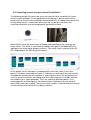
6.3
A design for Muscle-Feedback and –Rehabilitation.............................................................................................................................................................................. 43
6.4
Controlling a movie using an external Reed-Switch........................................................................................................................................................................... 45
6.5
A Camera - Mouse application with clicking functions...................................................................................................................................................................... 46
1.1
1.2
2.
3.
4.
5.
6.
BrainBay - User Manual
page 2 / 47
1. Introduction
This manual provides information and instructions for setup and usage of BrainBay,
an Application for Biofeedback, Neurofeedback and Human Computer Interaction.
BrainBay allows the graphical design of universal configurations for realtimeprocessing, display, storage and opto/acoustic feedback of biosignals, bioelectric
events, visual information or other sensor data.
BrainBay is part of the OpenEEG - project (http://openeeg.sf.net). It currently
supports several biosignal amplifiers, including:
• ModularEEG and MonolithEEG (openEEG)
• Optima2 and Optima4 (Neurobit Systems)
• OZC NIA
• PendantV3 (Pocket Neurobics)
• SmartBrainGames (SBG)
• QDS NFK 256 / openEXG
With one of these amplifiers and appropriate electrodes / sensors, following vital
parameters could be measured and utilized for biofeedback purposes:
•
•
•
•
•
•
•
•
•
Brainwaves (Electroencephalogram, EEG)
Heartbeat (Electrocardiogram, ECG)
Muscle Activity (Electromyogram, EMG)
Eye Movements (Electrooculogram, EOG)
Blood Volume Pressure (BVP)
Galvanic Skin Response (GSR)
Skin Temperature
accelleration, control switches
face-position, body movements (using a webcam)
BrainBay - User Manual
page 3 / 47
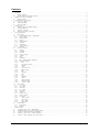
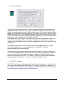
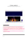
In a BrainBay Design-Configuration, these signals are connected to processingelements for feature extraction, transformation and visual / acoustic feedback.
The following figure shows a design configuration that connects two channels of an
EEG-amplifier to processing- and display-elements that provide visual and acoustic
feedback of signal parameters (for details on this design see chapter 6.1) :
1.1 Possible Applications:
•
•
•
•
•
•
•
•
Biofeedback- and Neurofeedback-Therapy indications:
tension-headache, migraine, post-traumatic stress syndrome,
tinnitus, epilepsy, chronic pain, cardial arhytmia,
attention deficit / learning difficulties, incontinence;
Rehabilitation Training, muscle- workout and relaxation, posture training
Realtime–Telemetry of Bodysignals
Patient Monitoring
Therapy Progress Control
Online and Offline Data Analysis
Human Computer Interaction, control of mouse-cursor + clicking-functions,
typing via an On-Screen Keyboard
Brain Computer Interface
1.2 Functional features of BrainBay (overview):
- Digital Filters, FFT-Displays (Bar-Graph, Spectrogram, 3d-View)
- math. Elements (correlation, threshold, trial averaging, expression-evaluator, ...)
- Multimedia feedback (Midi, Wav- and Avi-Playback, Bar Display, ...)
- Network transmission (using the Neuroserver framework)
- Reading and storage of archive-files in European Data Format (EDF)
- Webcam support and face-detection (for head-mouse support)
- HCI-functions (mouse control, keyboard events)
BrainBay - User Manual
page 4 / 47
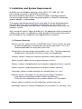
2. Installation and System Requirements
BrainBay uses the Windows operating system (Win7 / XP / 2000 / NT / 98 ).
A Linux-build is possible using the Wine-environment.
Miniumum hardware requirement is a Pentium-II laptop- or desktop-computer.
For more complex designs and/or fast graphic displays, an OpenGL-accelerated
graphics-adapter is recommended.
The compressed package containing the executable file can be downloaded from
http://brainbay.lo-res.org. To uncompress the package, you can use the 7-zip
freeware utility (download from http://www.7-zip.org) or any other utility that can decompress .rar files.
After running the installer “Setup_BrainBay.exe”, the application will be extracted into
a folder of your choice. A subdirectory named 'brainbay' will be created that contains
the executable file, the needed .dlls and subdirectories for resources.
2.1 Directory Structure
Archives: contains signal archives in P2/P3/EDF format. These archives are used
by demo configurations and could be used for own experiments. This is the
recommended folder for storing own archive files.
Configurations: contains design-configurations (.con - files). The delivered designconfigurations shall demonstrate main functions of the application
Graphics: contains images for the particle generator or other processing elements
Movies: contains videos for the avi-player element (.avi files)
Patterns: contains recorded patterns for the pattern-recognition element (.erp files)
Palettes: contains sample color palettes for display elements (.pal files)
Tonescales: contains sample tonescales for the Midi-Player (.sc - files )
Network: contains executables for the Neuroserver software framework.
(http://openeeg.sourceforge.net/doc/software/NeuroServer)
These files are needed to transmit or receive edf-files via TCP/network.
Sounds: contains audio files for the audio-player element (.wav files)
Skindialogs: contains a sample skindialog for user interaction (.ini and .bmp - files)
BrainBay - User Manual
page 5 / 47
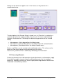
3. Window Overview and Main Menu
All main functions of BrainBay can be accessed through the main menu on top and
the status-bar on bottom of the application window. The design configuration which
consists of a connection of functional elements is shown in the Design Window:
The status bar on bottom of the application window provides information about the
current session time, the device status, and buttons for session control. The Play and
Stop - buttons or the respective hotkeys F7 and F8 can be used to start and stop the
session. Reset sets the position of archive files to their beginning and the session
time to 0 seconds. The Hide/Show Design - button or hotkey F5 controls visibility of
the design-window. The status bar itself can be hidden or displayed by pressing F6.
If there are archive-file readers present in the design configuration, the status bar
extends automatically and shows the progress of the playback. In- and out points can
be defined for the archive playback (see description of the EEG-amplifier and EDFreader elements)
The main menu provides the following entries:
Design:
Create a new design, load / save a design, exit application
Insert Element: Add new elements to the design
Session:
Run or stop the designed session
Network:
Start a neuroserver for network transmission
Tools:
Editors for color-pallettes and midi-tonescales
Options:
Application- and Device settings
About:
Program version and author information
BrainBay - User Manual
page 6 / 47
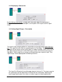
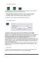
3.1 Options and Settings
By choosing Options->Application from the main menu, following window appears:
In section Communication, the default
value for the Sampling Rate is
selected. The sampling rate defines
the frequency of signal processing
throughout all desing elements. This
value should match the sampling rate
of the data aquisition hardware. For
the ModularEEG, sampling rate will
usually be 256Hz. When reading EDFAchive files with other sampling rates,
the value has to be adjusted
accordingly.
The section Video Capture Library
allows selection of alternatives for the
image acquisition library (currently,
only OpenCV is used internally).
The Midi-Audio Output section defines the Midi-Devices that will be active within
Brainbay. A Midi-Device could be a soundcard with midi-synthesizer, a wavetable
software synthesizer, or external Midi-devices like keyboards, drum-computers or
midi-controllers. Cable patch drivers like MidiYoke (freeware) or LoopBe (Win7compatible) provide virtual Midi-input and -output devices that build a bridge to other
midi-processing software running on the same computer.
To add a Midi-Out-Device to the list, select it from the combo-box which contains all
devices that are currently accessible in the system. To delete a device from the list,
just click the list-entry.
In section Refresh Intervals, the update rates for screen displays are set. User
Dialogs selects the refresh rate for element's parameter windows, Display Windows
selects drawing update rates for oscilloscopes, FFTs or meter windows. The refresh
interval is given in relation to the sampling rate: a value of 8 gives 32 updates per
second when a sampling rate of 256 is used.
The Session Startup section has options for application-initialisation: When Load last
design is chosen, the previously used design will be loaded. Auto-run starts the
design after being loaded. Main Window Minimized allows startup without opeingn
the application window.
If Options->Device is chosen from the main menu, the settings of the biosignal
amplifier element (e.g. ModularEEG, Neurobit Optima, etc.) will be opened, if such an
element is present in the design (otherwise an error message is displayed).
BrainBay - User Manual
page 7 / 47
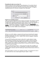
3.2 Color Palette Editor
The Color Palette Editor (activated via menu: Tools->Edit-Color-Palettes) can be
used to easily create color fades and pallettes for some display elements. Currently,
the color palettes are used by the FFT spectral analyser and the Particle Animator
elements.
To adjust the colors, use left- and right clicks into the color-window to set the update
region: A left-click sets the start and a right click the end point of the current region.
Using the smaller color selection fields or the scrollbars for RGB - composition, the
color value of the start or end point can be set and a color fade from start to end is
calculated. Thus, smaller regions or one big region can be created per just a few
clicks. A palette consist of 127 colors. Existing palettes can be load and modified
using the Import Palette button, new palettes can be saved using Export Palette.
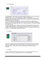
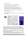
3.3 Tone Scale Editor
The Tone Scale Editor (activated via menu: Tools->Edit-Tone-Scales) can be used to
create own Tonescales for the midi-player element like major, minor, blues etc.
Sometimes it can be useful to make small scales with just two or three tones that fit
together.
The current tone is selected with
the scollbar, it will be played using
the given midi-output device,
channel and instrument. By
pressing add to Scale, the tone is
appended to the members of the
tonescale.
To play the whole or parts of the
scale, select a tone from the list of
member and use the cursor
up/down to browse the scale.
Use Load Scale and Save Scale to
modify existing scales or to create
new ones.
BrainBay - User Manual
page 8 / 47
4. Creating Designs
The process of creating session designs with BrainBay basically consists of the
following steps:
- Insert elements to the design window
- Connect signals from an element's output port to another elements input-port
- Adjust properties in the element's graphical user dialog
- Test the design with archive-, simulation- or realtime data
4.1 Inserting, Tagging and Deleting Elements
The Insert Element - entry of the main menu shows up five groups :
Signal Sources, Signal Targets, Processing - Elements and Others;
The fifth group, contains All elements in an alphabetical order. Generally, every
reasonable design will need at lest one signal source (like an EEG-Amplifier, a signal
generator or a file-reader) and one signal target (like a spectral-display or an
oscilloscope). An element can be selected by left-clicking the center. The active
element is drawn with a yellow border. It can be deleted with the Del - Key of the
keyboard.
By double-clicking the center of an element, its description-tag can be modified.
4.2 Connecting Elements
A connection is drawn by left-clicking an output-port of the active element and
dragging the line to a free input-port of another element.
Signal-sources have at least one Output Port (orange). The above picture shows 6
output ports on the EEG-element for the channels of the EEG-amplifier and a
seventh output port for the status of control switches.
Signal-targets have at least one Input Port (yellow). The oscilloscope-element
dynamically adjusts the number of its input ports, so one or more inputs can be
connected. Other processing elements usually have input and output ports.
BrainBay - User Manual
page 9 / 47
4.3 Displaying a Connection
By left-clicking a connection, a dialog with information about the connection is
displayed. It states the connected ports, a description of the signal and the signalrange.
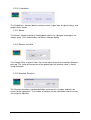
4.4 Setting Signal Ranges / Description
The signal-range and description of a connection can be adjusted by right-clicking a
port. This opens the Out-Port- or respectively the In-Port dialog. The description for
the signal can be written into the given field. The above example shows how to adjust
the signal range of Channel 2 of the EEG-signal source. For elements that possess
input ports, signal range for an out-port can be obtained from a specific input. Thus,
signal-ranges can be propagated to following elements.
The Input-Port Dialog for the oscilloscope-element (channel 2). The input-range for
the specific port can be adjusted or inherited from the connection. Adjusting the
input-range would make sense when a smaller range has to be displayed etc.
BrainBay - User Manual
page 10 / 47
5. Using Design-Elements
Design-Elements (Signal Sources, Signal Targets and Processing elements) are the
fundamental components for building a signal processing configuration in BrainBay.
Many elements provide a user-dialog to adjust their parameters. This user-dialog can
be displayed by right-clicking the center of an element. In the following, the BrainBay
design-elements and their usage will be described.
5.1 Signal Sources
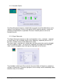
5.1.1 Generic Biosignal-Amplifier / EEG-Amplifier
This element provides an interface to different biosignal amplification devices which
are connected via USB / COM Port. It can also be used to record or playback archive
files. The element either works in live- or in archive mode (not both at the same time).
The device type or protocol version has to be selected via the DeviceProtocol combo
box. Depending on the connected device, several options can be selected, like the
number of active channels, usage of hardware flow control (usually disabled) or bidirectional communication to change device parameters (e.g. for the MonolithEEG).
Receiving live-data from the amplifier
Connect the amplifier to a Com-port of USB-Port, select the appropriate Com-Port
number from the combo-box. Select baud- and sampling-rates (e.g. 57600 baud,
256Hz), and the Resolution (e.g. 1024 for a 10bit resolution of the sampling values).
Select the device/protocol which is used by the amplifier firmware (e.g. ModularEEGP2 or ModularEEG-P3). Press button Connect/Disconnect Com Port. The connectedcheckbox should indicate that the port has been connected (if not, check Com-Port
and settings). To display live-data, connect an oscilloscope-element to the output
ports of the amplifier-element, press Play - button from the status bar and turn on
your biosignal amplifier.
BrainBay - User Manual
page 11 / 47
Recording live-data to an archive file:
Setup the connection to the amplifier as described above. Press button Record
Archive and choose a filename and folder to store the archive. Recording starts
immideately after confirming the filename (and starting the design). To stop the
recording and close the file, press the button Close Recording.
Playback of recorded archives:
Close an eventually openend Com-Port and press the button Open Archive. A dialog
will appear where an archive file can be selected. The device- and sampling-rate
settings will be modified according to the archive. When an archive file is opened, no
live-data can be processed by the EEG-amplifier element, and the status bar
extends: a slider shows the progress of playback and can be used for positioning in
the archive file. The current position in sedconds is shown in the Time -Field. Use the
Play-, Stop- and Reset- buttons to control playback.
With the In- and Out- buttons, a segment of the archive can be defined for loopedplayback. By pressing In or Out, the current position will be set as the new start or
end - point for playback. The Go to - button can be used for jumping to a specified
position, given in seconds.
Only one EEG-Amplifier signal source can be active in a given design. If more
physical devices should be used at the same time, multiple instaces of BrainBay
have to be started. It is however possible to have more than one archive player
active, using the EDF-Reader or File-Reader elements. To align the position of an
EEG-amplifier archive relatively to other archives, an offset for the archive in seconds
can be set in the user dialog.
When the EEG-Amplifier element is used to receive live-data from an amplifer, the
sampling rate for the whole system is controlled by the output of the EEG-amplifier
element: When a device sends 512 Packets per second, all other elements will run at
that speed.
When playing back an archive, the sampling rate will be set according to the rate of
this archive, but the rate can be changed using the Options - dialog.
BrainBay - User Manual
page 12 / 47
5.1.2 Neurobit Optima
The Neurobit element features a dedicated connection to the Neurobit devices (Lite,
Optima-2 and Optima4). Similar to the generic EEG-amplifier element, archive file
recording and plackback are provided. For more inforation please refer to the
Neurobit manual.
5.1.3 Signal Generator
The Signal-Generator element can be used to produce sinus-, rectangle-, sawtoothor ramp-signals with selectable center value, frequency, amplitude, phase-shift. If
desired, a random noise can be added to the signal.
The signal type is selected via a combo-box, the other parameters can be changed
with the respective silders. The maximum amplitude (the range of the amplitude slider) can be changed by right-clicking the output port of the element.
The checkbox enable Input Ports controls the accessibility of frequency- and phasesettings via input ports. Using the input ports, these settings can be modified by other
elements or by a user dialog.
BrainBay - User Manual
page 13 / 47
5.1.4 Constant
The Constant element provides a fixed value on it's output port :
5.1.5 EDF-File Reader
The EDF-File Reader element can be used to read previously recorded file in
European Data Format. EDF is a format for the exchange for biological signals
(see http://www.edfplus.info). The header of an EDF file stores various information
about the recording: date, patient data, recording device, sampling rate, data
segments, signal ranges and descriptions for the data channels.
This information is displayed in the user dialog of the EDF-File Reader element after
a valid file has been opened.
Choose a channel from the combo box to display it's information. EDF-files can have
many channels. However, BrainBay's channel limit is set to 32. The signal range of
the output ports is set by Physical Minimum to Physical Maximum of the
corresponding channel. Similar to the EEG-Amplifier archive playback, the status bar
extends when an EDF-archive has been opened successfully, to enable playback
control and positioning in the archive. (see EEG-Amplifier element). The field Initial
delay allows specifying an offset to align this archive file with other files for playback.
BrainBay - User Manual
page 14 / 47
5.1.6 File-Reader
The File-Reader element can be used to read channel data from a text file. Using the
File Format combo box, the type of storage and the delimiters for rows and columns
can be selected. For more information please see the File Writer description.
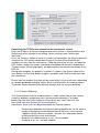
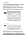
5.1.7 TCP-Receive
Similar to the EDF-Reader element, the TCP-Receive element provides EDF channel
data to other elements. The difference is that the data comes from a network
connection and not from a local file. The TCP-Receive element connects to the
neuroserver software framework by Rudi Cilibrasi which is also part of the OpenEEG
project (see http://openeeg.sourceforge.net/doc/sw/NeuroServer).
To use the TCP-Receive element, a neuroserver has to be running on a known host
in the network or on the local host. Sending- and receiving clients can connect to this
service. Thus, clients can send / receive live biosignal data and recorded EDFarchives to / from the neuroserver.
An easy way to test the TCP-Receive element is to start a neuroserver and an EDFreading client on the local host (by using the Network- entry from the main menu) The
figure shows the running service, with an EDF-client connected.
BrainBay - User Manual
page 15 / 47
Connecting the TCP-Receive element to the neuroserver service
Enter the IP-adress of the host computer where the service is running into the field
Neuroserver of the element's user dialog (when running a local service type
'localhost').
Press the Connect - button. In case of a successful connection, the Status-listbox will
show the line 'OK' and the combo-box Biosignal-Session will be filled with the
available sessions from the neuroserver. Choosing one of the sessions will open the
EDF-stream, display the header information and update the element's output ports.
The port ranges for the output ports are obtained from the channel-information of the
EDF-file.
During data reception, the progress in packets is shown in the Status-listbox of the
user dialog. Use the Stop -button to bypass reception and Close to disconnect from
the neuroserver.
Please take into account that there will be some delay in the transmission, depending
on network bandwidth and other factors like the receive buffer for incoming values.
The button Empty Receive-Buffer discards packets that are currently buffered
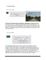
5.1.8 Camera (Webcam)
The Camera element can be used to process a video stream from a local camera
(usually a webcam) and perform face- and movement-detection. For imageprocessing, the Intel Open Computer Vision library was used. (OpenCV, see
http://www.intel.com/research/mrl/research/opencv )
In particular, three tasks can be performed by the Camera element:
-
-
Perform face detection and feature tracking algorithm on the live camera
images and output the estimated position of the user's nose and chin.
Together with the Mouse Controller - element, this information can be
used to control the cursor and clicking.
Record a live-videostream to an .avi - file to harddisk
Playback of an .avi - file from harddisk
BrainBay - User Manual
page 16 / 47
To use the camera element, a webcam or another camera needs to be connected
and visible to the system (installation of correct device drivers etc). After inserting the
camera element into the design, the device is openend and the live-stream is
displayed in a seperate window.
The display interval can be set using the field show every n frame in the element's
user dialog. Using a good webcam, 30 frames per second can be captured even on a
small Atom CPU (netbook).
Three radio-buttons control the mode for the Camera-element:
'No archive operation' is usually used for feature tracking (head-mouse designs).
When 'Record to archive' is pressed, an open-file dialog can be used to choose a
filename and folder for the avi-file. Then, a dialog for codec-selection appears. The
codec compresses the image frames befor writing them to disk. Choose a codec that
does not use much processor time ('uncompressed' is surely the fastest, but gives
very large video archives, 'Cinepak' or 'Microsoft video1' are possible alternatives).
After selecting the codec and starting the design, the video frames are written to the
file until the Stop Camera - button is pressed, which also closes the archive file.
'Playback from archive' also displays an open-file dialog where the .avi file of a
previous recording can be chosen. After starting the design, the video stream will be
delivered from the archive and not from the webcam. This is also possible wehn no
webcam is installed in the system.
Feature Tracking
The element will perform a detection of a frontal human face on the videostream from
camera or video archive file. When a face has been found, the nose and chin
positions are estimated and tracked by an optical flow algorithm. The coordinates of
nose and chin relative to the last image are sent to the element's output port. After
appropriate filter- and resize-operations, these coordinates can be used by the
Mouse-Controller element to perform mouse movement and clicking operations (for
details see the Camera-Mouse example design)
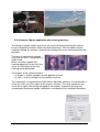
5.1.9 Skindialog
The Skindialog Element provides a custom drawn, skinned user dialog to the design.
Buttons and sliders with mouse-sensitive areas can be defined using bitmap graphics
and can be saved into a dedicated .ini file. The values of the sliders or buttons can be
changed by the user during the desing is running, and the current values are
available to other elements at the skin dialog element’s output port. Thus, special
BrainBay - User Manual
page 17 / 47
dialogs can be drawn to support users in their access or key features of a
complicated design.
The description of the Skinned Dialog is stored in an .ini-File which is created via a
small design tool in the settings window. Here, the skin file name and the bitmap
filenames can be defined. The bitmap files define the appearance of the skinned
dialog:
•
•
•
<bitmapname>_Active.bmp defines the dialog-image
<bitmapname>_Selected.bmp defines the dialog-image with selected buttons
<bitmapname>_Mask.bmp defines the dialog’s opaque area;)
Buttons and Silders can be created via the dedicated sections. The active area for
button or slider can be drawn into the bitmap using the mouse.
See the skin_readme.txt file in subdirectory Skindalogs for more details.
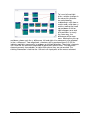
5.2 Processing Elements
Processing elements are used to perform signal adjustments, transformations, apply
thresholds or combine singnals to get the desired parameters for the feedback
processes. BrainBay currently has several signal processing elements which will be
introduced in the following sections.
BrainBay - User Manual
page 18 / 47
5.2.1 Averager
The Averager element puts out the mathematical average of the last n samples. The
number of samples can be selected by the Interval scroll bar. If 0 is selected, all
samples will be averaged (this can be useful to accumulate data for a whole session).
5.2.2 Comparator
This element compares it's two input values in a way given by the user.
When the selected condition is true, the value of input A is routed to the elements
output port.
If the condition is false, the output of the element will be INVALID_VALUE, or the
chosen value in the respective edit field.
(In case one of the inputs is INVALID_VALUE, the condition will be false).
5.2.3 Correlation
This element calculates the cross-correlation between the two signals connected to
input 1 and input 2 in a selectable Interval of samples. Correlation is a measurement
for the linear relationship between the two signals. The output will be between 1 (fully
correllated) 0 (uncorrelated) and -1 (fully inverse correlated).
BrainBay - User Manual
page 19 / 47
5.2.4 Counter / Display
Depending on the selected type, the Counter element is used to:
• count transitions from or to INVALID_VALUE (generated e.g. by a false
condition or an invalid threshold in using the respective elements)
• measure frequency of true-false transistions (in Hz)
• show the plain input value (as integer or float value).
The value of the counter is presented at it's output port, and, if desired, in a seperate
window with selectabe fontsize and color. The counter can be set to an initial value
by pressing Reset Counter Value or by sending a valid value to the “reset”-input port.
This reset will also be done when the session is resetted using the status bar
5.2.5 Debounce
The Debounce element can suppress frequent changes to INVALID_VALUE. This
could be used to constrict the generation of events when a signal is close-by a
threshold level. The interval is given in samples.
5.2.6 Delay
The delay element delays the input singnal be the given number of samples.
BrainBay - User Manual
page 20 / 47
5.2.7 Differentiate
The differentiate element calculates the difference from the previous to the current
sample value. (This element does not have a settings dialog).
5.2.8 ERP - Detector (Pattern Recognition)
The ERP-Detect element can record and detect signal patterns in time domain. It can
be used to perform trial averaging, what is a popular technique for extracting event
related potentials (ERPs) from a noisy EEG signal. The Epoch-length of the trials, the
pre-trigger interval and the number of trials can be written into the input fields. The
display range is obtained from the signal input port. Adjust this range by right-clicking
the input port.
The button Start recording activates the recording- and averaging-mode of the
element. In this mode, the element waits for a TRUE value on it's trigger input port.
This trigger singnal could come from a threshold - element, from an external switchbutton or from a signal generator etc. After the trigger signal has been received,
epoch-length samples are recorded and added to the internal buffer of the element.
Then the next trigger input is awaited and the next trial is recorded. After a number of
trials, the noise gets less due to the averaging process and the exctracted signal
remains. This signal can be saved to an .erp file.
When the ERP-Detect element is not in it's recording state, it's continuously
calculates the linear difference between the recorded signal and the last epoch
length samples that came into it's singal input-port. The output-port presents the
similarity with the recorded signal in percent (0-100).
BrainBay - User Manual
page 21 / 47
5.2.9 Expression Evaluator
The Expression Evaluator can have up to six input ports, which automatically extend
when a signal is connected. The input signals are referred to as A, B, C, D, E, F and
can be combined with decimal constants, elementary functions, unary and binary
operations to a mathematical expression that is evaluated when the session is
running. The result of the expression is presented at the element's output port.
The evaluator implementation builds upon the open source library GNU-Libmatheval.
(see http://www.gnu.org/software/libmatheval)
Supported elementary functions are:
exponential (exp), logarithmic (log), square root (sqrt), sine (sin), cosine (cos),
tangent (tan), cotangent (cot), secant (sec), cosecant (csc),
inverse sine (asin), inverse cosine (acos), inverse tangent (atan),
inverse cotangent (acot), inverse secant (asec), inverse cosecant (acsc),
hyperbolic sine (sinh), cosine (cosh), hyperbolic tangent (tanh),
hyperbolic cotangent (coth), hyperbolic secant (sech), hyperbolic cosecant (csch),
hyperbolic inverse sine (asinh), hyperbolic inverse cosine (acosh),
hyperbolic inverse tangent (atanh), hyperbolic inverse cotangent (acoth),
hyperbolic inverse secant (asech), hyperbolic inverse cosecant (acsch),
absolute value (abs), Heaviside step function (step) with value 1 defined
Supported unary operation is unary minus ('-').
Supported binary operations are:
addition ('+'), subtraction ('+'), multiplication ('*'),
division multiplication ('/') and exponentiation ('^').
Usual mathematical rules regarding operation precedence apply.
Parenthesis ('(' and ')') could be used to change priority order.
Blanks and tab characters are allowed in string representing function;
newline characters must not appear in this string.
5.2.10 Filter
The Filter element provides digital low-pass, high-pass, band-pass or band-stop
filters. A low pass filter will filter out high frequencies and let low frequencies pass the
filter. A high pass filter does the opposite - it will filter out low frequencies and let high
frequencies pass. A band pass filter will filter out lower and higher frequencies and let
middle frequencies pass the filter. A band stop filter will filter out the middle
frequencies and let lower and higher frequencies pass the filter.
BrainBay - User Manual
page 22 / 47
The filter can have bessel- or butterworth - type. The bessel-filter has a slower roll-off
in frequency domain (meaning it is less precise in attenuating around it's corner
frequencies) but does not have so much ringing (overshoouting) in time domain.
The Filter Type, Filter Order and the frequency - limits for the filer can be selected in
the user dialog. A higher filter order gives a sharper response in frequency domain
but a longer delay in time domain. When the button Apply is pressed, the filter
response in frequency domain is shown in the given display range. The display range
can be adjusted be typing new values in the bottom left and bottom right fields.
The filter shown above lets frequencies around 10Hz pass without attenuation.
Frequencies below 6 Hz or above 14 Hz are attenuated heavily. For more information
on the usage of filters see the design examples. The Filter - element uses the free
FidLib library by Jim Peters and Tony Fisher (see http://uazu.net/fiview)
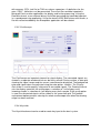
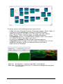
5.2.11 FFT (spectral analyser)
The FFT element performs a fast fourier transformation on the connected signal. This
shows the frequency components that are present in the signal, just like the ear can
detect the different tone-heights that are present in a sound. Using the FFT -element,
the changing frequency-components of for example brainwaves can be displayed as
BrainBay - User Manual
page 23 / 47
a bar-graph, spectogram or 3d- landscape. The kind of display can be changed using
the Style combo-box.
The Calc-Interval sets the number of samples that are buffered before the next
transformation is done. An interval of 25 samples gives about 10 transformations per
second at 256 Hz sampling rate.
The number of Bins defines the distinct frequency components (= bands). Many bins
give good frequency resolution but slow reaction in time. Range selects the bands to
be displayed (in Hz). Align (left, right, bottom) rotates the display.
A color palette can be used to map the intensity information to colors, what is
necessary in the 2d and 3d - views (for usage of the color palettes see palette editor).
The Gain (%) amplifies or attenuates the
signal before the FFT is done. The Gain(x), (y) and -(z) affect the display and are effective
in the 2d and 3d views.
When using the 3d -display, left- or rightclicking and dragging the display window will
change angle or position of the view (see
section design examples).
The FFT-element has two output ports: Average and Power. The first gives the
average freuquency of the bands in the selected range, the second gives the
average power (magnitude) of the bands in the selected range.
5.2.12 Integrator
The Integrator element continuously sums the incoming values. Pressing Reset sets
the buffer to zero, this is also done when starting or resetting the session.
5.2.13 Limiter
The Limiter element allows to define upper and lower bounds for the input signal.
BrainBay - User Manual
page 24 / 47
5.2.14 And, Or and Not
The logical And, Or and Not elements do not have user dialogs. They perform the
logical operations on the inputs and output the result.
And outputs TRUE_VALUE when none of it's inputs is INVALID_VALUE
Or outputs TRUE_VALUE when at most one input is INVALID_VALUE
Not outputs TRUE_VALUE when the input is INVALID_VALUE
In all other cases, the elements will output INVALID_VALUE
5.2.15 Matlab Transfer
The Matlab - element can be used to transfer sample buffers to the Matlab
application for further processing (see http://www.mathworks.com). Matlab is
commonly used in academic and scientific signal processing. As this is a commercial
application, the needed .dlls cannot be delivered with brainbay, and the Matlabelement will only work if you have a licenced version of matlab on your system.
The element can process up to six input ports named A, B, C, ...
During operation, the input values will be collected in buffers of given size. By
pressing Call Now, the buffers are transferred to Matlab and can be accessed via the
Matlab-variables A, B, C ... and a Matlab-function of given name will be called. The
result (the ANS-variable) will be transferred back to BrainBay and presented on the
output of the Matlab-element.
When Call Periodic is selected, the transfer will be done automatically when a new
sample arrives, this will only work for matlab-functions with low complexity / short
execution time.
5.2.16 Max
The Max - element calculates the maximum of a numer of connected signals and
outputs this value. (This element does not have a settings dialog)
BrainBay - User Manual
page 25 / 47
5.2.17 Magnitude
The Magnitude - element can be used to calculate the activity in a certain frequency range of a singal. This is oftern referred to as 'power in pass-band'.
The filter type is selected via combox-box can be Bessel-Bandpass or ButterworthBandpass (for more details on filters see the Filter - element or Jim Peter's FiView application, http://uazu.net/fiview).
The Center (Hz) and Half Width (Hz) - parameters adjust the pass-band, where
activity shall be measured. Example: when you want to measure Alpha-frequencies
of brainwaves in the range from 10 to 12 Hz, select a center of 11 Hz and a half width
of 1 Hz for the filter.
The filter order controls the 'sharpness' of the cut-off of unwanted freuqency-ranges.
A higher order gives better cut-off, but the response of the filter in time will be less
accurate. The Magnitude - element outputs the activity in the given passband, a gain
value (in %) can be applied to amplify the output.
5.2.18 Mixer
The Mixer - element can be used to merge up to four input signals into one output
signal. The amplification-ratios are given with the corresponding silder-bars. Using
the buttons Chn1 - Chn4, presets for solo-output of the selected channel are
activated.
5.2.19 Min
The Min - element calculates the minimum of a numer of connected signals and
outputs this value. (This element does not have a settings dialog)
BrainBay - User Manual
page 26 / 47
5.2.20 Peakdetect
The Peakdetect - element detects extreme-values (signal tops or signal valleys) and
outputs these values.
5.2.21 Round
The Round - element rounds a floating point value at its input port and outputs the
integer value. (This element does not have a settings dialog)
5.2.22 Sample and Hold
The Sample-Hold - element stores the current input-value when the button Sample is
pressed. This value will be present at the output-port until another value is stored
using the button.
5.2.23 Standard Deviation
This Element calculates standard deviation and mean of n samples and puts the
results to the ouput ports. The number of samples for the calculation interval can be
set using the slider bar.
BrainBay - User Manual
page 27 / 47
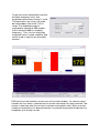
5.2.24 Threshold / Meter
The Threshold - element combines the following functionalities:
- Averaging and amplification or attenuation of the incoming signal
(using the slider bars from the Preparation-section)
- Setup of fixed upper- und lower bounds for the signal (thresholds)
If the values are not in the specified range, the elements outputs
INVALID_VALUE, otherwise the signal will be passed to the output port.
- Generation of dynamic upper and lower bounds, using a percentage of the
previous n samples
- Passing only rising or falling values
- Display of a Meter - window to show the current value of the signal and the upper
and lower bounds
The minimum and maximum values of the slider-bars for threshold selection are
obtained from the connected input signal. This range can be adjusted by rightclicking the input port. Dynamic calculation of thresholds will be performed if non-zero
values are used for the upper limit or lower limit - parameters: the new threshold
values will be set to in-/exclude a given percentage from the last Interval number of
values.
If rising- or falling values is selected, only progressive or regressive values will pass
the threshold. In the Meter Window - section, font size, bar size, colors and caption
for the meter display can be selected.
The Threshold element is a useful tool for feedback-purposes, where the reaching a
certain state like high or low activity is desired. Combined with for example a Midi element, feedback tones could be generated when this level is reached.
BrainBay - User Manual
page 28 / 47
5.3 Signal Targets
5.3.1 AVI – Player
The AVI-Player element can be used to display and navigate avi-movies. The value
that comes into the input-port of the element is interpreted as frame number. This
frame will be shown in a seperate display window. Using rising or falling values, the
movie can be watched forward or backwards. The sound of the AVI-movie will not be
present at playback (use the Media Player element to include sound output). A videocodec that can decode the given avi-file has to be installed on the system to use the
AVI-Player element.
5.3.2 Com- Writer
The COM-Writer element can be used to send command and data values to a
connected Monolith-EEG amplifier in bidirectional mode (using P21 firmware
protocol) . Using the Com-Writer, runtime options of the MonolithEEG like baud- or
sampling rate can be changed and the digital I/O- ports of the MonolithEEG can be
set. One command/data frame consist of three bytes that can be defined using the
input fields of the user dialog. The frame is sent by pressing the button. When
triggered sending is enabled by the user option, the frame will be sent every time an
input different from INVALID_VALUE is received by the trigger input-port.
BrainBay - User Manual
page 29 / 47
5.3.3 EDF- Writer
The EDF-File Writer element can be used to created a biosignal archive in European
Data Format (see http://www.edfplus.info). The header of an EDF file stores various
information about the recording: date, patient data, recording device, sampling rate,
data segments, signal ranges and descriptions for the data channels. This
information can be set using the data fields of the user dialog.
The description for the connected channels can be set using the Channel combo-box
and the corresponding data fields. When all channels have been connected and
labelled, the button Create File can be used to choose location and file name for the
EDF file to be created. The recording of channel data can be controlled by the
buttons Start Recording and Stop Recording. After recording, don't forget to press
Close File to finish the writing process and close the file.
5.3.4 File – Writer
The File-Writer element can be used to generate a file with channel data for
processing in other applications. Using the File Format combo box, the type of
storage and the delimiters for rows and columns can be selected. When using ASCIIInteger Values, a human-readable text file will be generated. If more than one
channel is connected to the element, the channel values will be written as columns
BrainBay - User Manual
page 30 / 47
with commas (CSV- text file) or TABs as column seperators. As delimiters for the
rows, CR/LF - delimiters can be generated. These text files could be imported in
Microsoft Excel or other applications for display and further processing. Using the
Raw/Wav format, a one-channel binary file will be generated that could be imported
in a sound-processing application. Using the format ASCII-BioExplorer with header, a
file with valued readable by the Bioexplorer application will be created.
5.3.5 Oscilloscope
The Oscilloscope an important element for signal display. The connected signals are
viewed in a seperate window which can be freely resized. During runtime, a data grid
showing the signal ranges and the current second can be displayed. The background
color and signal colors are adjusted using the color-picker - buttons. The DisplayGain slider is used to amplify / attenuate all connected signals. The Drawing-Interval
sets the display speed for the oscilloscope: a selection of 1 will display every
incoming sample, a selection of 4 will display every forth sample. If the group option
is used, the connected signals will be shown in the same data grid. The gradual
replacement option prevents clearing the whole oscilloscope area when the drawing
range has been reached.
5.3.6 Keystrike
The Keystrike element can be used to create key input to the local system.
BrainBay - User Manual
page 31 / 47
Using the settings dialog, normal and virtual keycodes can be selected, and pressand release actions can be added to a list. Thus, a desired key sequence can be
composed (e.g. Alt+F, or Ctrl+Alt+Del, etc.). The key sequence is generated by
sending a valid value to the trigger input port.
5.3.7 Parallel Port IO
The Port IO element can be used to control the parallel port’s voltages via BrainBay
signals. Thus, external devices can be interfaced to the system via transistors or
relails without the need of an extra controller. The Parallel Port IO element needs ther
PortTalk.sys driver to operate which has to be copied to the windows/system32
folder.
The 8 Bit Values of the Parallel Port interface can be controlled by the respective
input ports (valid / INVALID_VALUEs sent to the ports). The elements features
periodic updates, triggered updates (by input into the trigger port), and special bitpatterns for true and false inputs.
5.3.8 Particle Animation
BrainBay - User Manual
page 32 / 47
The Particle Animation element provides a graphical particle system that can be
controlled using signal values from up to six input ports. The particle system can
produce nice visual effects like color fountains, flames, star-flights or, in combination
with signal generators, moving circles and other geometric figures in 3d. The System
can be influenced by changing the current parameter using the Range silder-bar.
Paramters for the Particle System:
Number of Particles, Generation Interval
Slowdown, Color
X-, Y-, Z- Position
X-, Y-, Z- Speed
X-, Y-, Z- Gravity
Life Span, Randomizer
Recommended usage of the Particle System:
- select a color palette for the particles (see palette editor)
- choose one of the above parameters from the combo box and
adjust it's value to gain a desired effect
- repeat previous step for other parameters, until you have the effect you like
- connect a signal to input port 1 of the element
- select a parameter that suits well to the type of feedback you want
- select Remote Control by 1, now the value of this parameter will change
according to the signal connected to input port 1.
Use the get minimum and get maximum buttons to set the current input-value as new
minimum or maximum for the parameter value. This way, the upper and lower
bounds for remote-controlling the paramter can be set.
When reset min and max is pressed, the min and max values will be reset to the
original values for this parameter. The best results for the particle system can be
gained by using an OpenGl-accellerated graphics card.
5.3.9 Midi Output
BrainBay - User Manual
page 33 / 47
The Midi-Output element provides Midi-Audio feedback for the connected signal.
Toneheight, volume, tone interval and pitchbend can be controlled via the input ports.
The signal range of the connected input signals is mapped to the selected volume
range or tone scale. (As always, the signal range can be modified by right-clicking the
input port).
For Output Device, a Midi-Output device that has been enabled via the
Options->Application menu can be selected.
By specifying a Channel number, 16 midi channels can be used, which allows more
midi-elements with different instruments to work in parallel. (Channel 10 usually
selects the Drum-Set).
The Note Interval sets the speed for tone generation: an interval of 1 will generate a
midi tone every time a new sample arrives (this usually is much too fast - a setting of
25 gives about 10 tones per second when a sampling rate of 256 is used, which is
still very accurate).
Via Instrument or Controller, the midi instrument name or midi-controller number can
be selected. Using midi-controllers makes sense if an external midi-device like a
synthesizer or drum-computer is connected, or a Midi-software-router to transfer the
midi-commands into other running sound applications is available.
With the button Import Tones, a tone-scale generated with the Tone Editor is
imported and used as a harmonic filter for the midi-notes. (see Tone Editor)
The Hold buffer sets the number of tones that will be left on at the same time.
The Pitch Range and Volume Range edit fields allow to specify ranges for pitch bend
and channel volume with respect to the currently received values at the respective
input ports. The Pitch and Volume update interval defines how often pitchbend and
channel volume paramenters are updated.
If play only if note changes is selected, two consecutive notes will only be played if
they are different. Mute on false input mutes the currently played tone if an
INVALID_VALUE is sent to the note input port. Mute all mutes all currently played
tones.
BrainBay - User Manual
page 34 / 47
5.3.10 Mouse Controller
The Mouse Controller element provides an interface to the mouse-cursor and clicking
functionalities. The current screen-resolution can be set as maximum X- and Ypositions for the cursor (the auto-detection feature can be used to set these values
automatically). During session runtime, the present values at the xPos- and yPosinput ports will influence the cursor position. If the x-Integrator and y-Integrator
options are selected, the input values are interpreted as relative changes (Joystick
mode), if not, absolute positions will be used.
A left click will be performed when a value other that INVALID_VALUE is passed to
the left-Clk input port. Right-clicks, drag-clicks and double-clicks can be performed in
the same way, using the respective input ports.
The option activate Click-Selector displays a seperate tool-window which allows
selection of right-, double- or drag-clicks without using the corresponding input port.
Thus, a right-, double- or drag-click can be performed by choosing the type of the
next click in the click-selector window, and the special click can be performed with
the normal left-click action.
The Dwell-Time can be used to perform a left-click operation by holding the mouse
cursor in a given screen-area (defined by dwell radius and reset radius) for a given
time. Thus, clicking can be performed without having a seperate control signal
connected to the left-Clk port. The current dwelling time and an indication value when
a dwelling click is performed are available at the element’s output ports. Dwelling and
the whoel mouse operation can be enabled / disabled via the dedicated input ports,
or via the stanby-buttons in the user dialog.
A useful source for the Mouse Controller could be the Camera element (feature
tracking enabled). After some filtering and scaling, the estimated face positions that
are put out by the Camera element set the cursor position for the mouse and give a
functional head-mouse interface (see design examples).
BrainBay - User Manual
page 35 / 47
5.3.11 Sound Player
The Sound-Player element can be used for triggered playback of a short audio-file.
Supported file formats include wav, mp3, voc and aiff. The file could contain sound
effects or reward tones of about 1 to 20 seconds length. The element is not suited for
longer music files because of long loading / conversion times (use the Media Player
element for longer files). The input-ports control starting of the sound (on), the current
volume (vol) and the playback speed / toneheight (speed). The sound will be played
when the on input is different from INVALID_VALUE.
If the option play only changes is selected, the sound will be played only once if the
value of the on input-port does not change. The Repeat Interval can be used to
select a minimum duration until the sound is triggered next time, thus a pause can be
introduced.
The Sample Buffer Size sets the size for the internal playback buffer, this value
affects the audio latency / system performance. Using values < 4096 is
recommended for accurate playback.
The ranges for volume (Input-Range) and speed (Center and Factor) are obtained
from the connected input signals and can be set manually by changing the values in
the user dialog. The reverse option changes speedup or slowdown of the sound
when the speed input values rise. The Center - value sets the value for playback at
original speed and the Factor - value sets the gain for speed-changes.
5.3.12 TCP – Sender
The TCP-Sender element can be used to transfer signal channels via network, using
the neuroserver software by Rudi Cilibrasi. To establish connection, a neuroserver
has to be running on a known host computer in the network or on the local host. (see
http://openeeg.sourceforge.net/doc/sw/NeuroServer).
BrainBay - User Manual
page 36 / 47
The above picture shows a running neuroserver on the local host. The TCP-Sender
element connects to this service as a client which sends biosignal data in EDFformat.
Connecting the TCP-Sender element to the neuroserver service
As in the EDF-Writer element, the first thing to do is to fill out the descriptions for the
EDF data header and channel information (see EDF-Writer element). The signal
range for a specific channel is obtained from the connected input signal, it can be
modified by right-clicking the input port. To connect to the neuoserver, enter the IPadress of the host computer where the service is running into the field Neuroserver of
the element's user dialog. (when running a local service type 'localhost'). Press the
Connect - button. In case of a successful connection, the Status-listbox will show the
lines 'Entering EEG mode' and 'OK'.
Start Sending and Stop are used to contol the data flow to the neuroserver. The
button Send to neuroserver directly sends a neuroserver command written in the text
field to a connected service. Use Close to disconnect from the service.
BrainBay - User Manual
page 37 / 47
5.3.13 Media Player
The media player element uses the Windows MCI interface to playback video or
sound-files. AVI, WMV, WAV, MP3 and other formats could be used. After a
mediafile has been selected, it is played by receiving a value different from
INVALID_Value at its play input port. Volume and playback speed can be adjusted by
the Vol and speed ports, if supported by the media format (1000 sets full volume /
normal speed). The center position is used to calculate the actually media file
position by adding the relative value sent to the position input port. This position data
and the update interval for positions are given in milliseconds. Input values sent to
the step port cause a video file to step one frame forward (if supported by the media
format).
BrainBay - User Manual
page 38 / 47
5.4 Other Elements
5.4.1 Documentation
The Documentation element simply provides a text box. It can be useful to describe
the overall purpose of the design, special design elements or archive files that have
been recorded with this design.
5.4.2 Ballgame
The ballgame is an example for a feedback-game, implementing a low-end version of
the classic 'arkanoid' - arcade game originating in the early 80ties. The purpose of
the game is to catch the ball with the moving bar (the racket). The position of the
racket is contolled by the input port of the element. Racket Size and Speed of the ball
can be controlled via the user dialog. The best number of hits is displayed in the
game window and stored by the element.
BrainBay - User Manual
page 39 / 47
6. Example Designs
The following examples will show practical applications of design elements.
Three designs will be described briefly, one for neurofeedback, one for muscle
feedback and a head-mouse design.
6.1 A design for Alpha / Beta – Neurofeedback
The following design shows realtime-processing of a two channel monopolar EEG
recording. Three Silver Electrodes were mounted at C3, C4 and Cz - positions
according to the 10/20 - system. The reference point was Cz. An abrasive conductive
gel was used to improve electrode-skin contact. The impedance of the electrodeskin-connection was about 10kOhm. Sampling was performed by the MonolithEEG
amplifier at 256 Hz, using the P2 firmware protocol and a baudrate of 56700 bits/sec.
The oscilloscope window shows the EEG signals which have been 50Hz - filtered.
Two FFT - spectrum analysers show the frequency spectra of the EEG signals (brainmirror display). Magnitudes in alpha- and beta range give audio feedback via multiple
midi channels. The two meter-windows show current magnitudes and thresholds for
the audio-output.
BrainBay - User Manual
page 40 / 47
The design consists of the following elements (per channel):
- a filter of the type 'Bandstop Resonator', Bandstop-frequency = 50 Hz, Order = 8
- a connection to the oscilloscope, to display the filtered EEG signal
- a FFT spectral display, calculation every 10 samples, gain 250, 128 Bins,
display range 3 - 40 Hz, style: bar-graph, user-edited color palette
- two magnitude elements, using butterworth - bandpass filters in the range of
8-12 Hz and 16-20 Hz, filter order 4, gain 100 %
- an expression evaluator that adds the two calculated magnitues
- a threshold element, averager set to 223 samples, threshold set to > 21,5 uV
- a midi tone generator, using a user-defined harmonic scale and an
output interval of 70 samples.
above left: the frequency - response of the 50Hz - bandstop filter
above right: the Style parameter of the FFT-element was changed from bar-graph
to 3d line-grid
BrainBay - User Manual
page 41 / 47
6.2 Heartbeat-Feedback from a multichannel EDF-recording
The following extracts the heartrate from a 17-channel multimodal biosignal recording
stored in an EDF-file. ECG and frequency-spectra of the contraction of the heart
muscle are displayed. For calculating the heartrate, a dynamic threshold level is
applied. Acoustic feedback for the heartbeat is created by three midi-generators.
The ECG-output of the
EDF-file reader source is
connected to display- and
processing elements. The
first FFT-display is in 3dmode, the second in
moving spectogrammode. Both FFTs use 32
bins and a calculation
interval of 4 to enable fast
displays. The thresholdelement detects the Rwave of the QRScomplex.
The heartrate is calculated by a counter-element which counts the frequency of
threshold-activation. The output of the counter (given in Hz) is multiplied by 60 using
an expression-evaluator to get beats per minute. The second counter is used only as
a display for the value.
BrainBay - User Manual
page 42 / 47
R-Wave-detection:
The R-wave in this ECGrecording is characterized by
a large negative spike. This
peak can be used to detect
one heart-beat with a threshold element. A way to adapt
to the variing amplitude of the
heart-signal is to use a
dynamic threshold: the level
to pass values is set to 4% of
all signal values in the last
200 samples.
For audio feedback, three midi-generators with the same type of harmonic tone-scale
were used. As the detected peak of the R-wave can be very short, a fast tone outputinterval is needed to recognize each heartbeat. Therefore, the output-intervals for
the midi-elements were set to 1, 2 and 3, which corresponds to 100, 50 and 33 tones
per second. (the sampling rate for this EDF-recording is 100Hz). The different
intervals for tone-generation lead to sightly different notes which fit together because
of the harmonic scale.
6.3 A design for Muscle-Feedback and –Rehabilitation
The following design can be used to perform muscle feedback for training and rehabilitation purposes. The example recording was done with a MonolithEEG amplifier
running in P21-bidirectional mode and at 600 Hz sampling frequency. The amplification has been set to a low level, corresponding to high muscle potentials of about
500 uV. Muscle activity could be mesured using standard BlueSensor EMG surfaceelectrodes attached to the left and right tigh. Four electrodes used in bipolar mode
give a two-channel setting.
BrainBay - User Manual
page 43 / 47
To get the muscle contractions and filter
out lower-frequency noise, one
magnitude-element per channel is used.
The parameters are set to a 4th-order
bessel bandpass filter of 85-115 Hz
range. The magnitude output is
averaged for a period of 300 samples,
(half a second at 600 Hz sampling
freqeuncy). Thus, the fast and jumpy
magnitude-value is made smoother and
can be used as input for the thresholdelement.
EMG-activity of two locations can be seen on the meter-displays. An acoustic signal
rewards the user when a selected level of muscle-contrcation has been reached. Two
counters show how often the muscles have been contracted in total. When a certain
number of contractions has been performed, a sound will be played that indicates the
completion of a training-session.
BrainBay - User Manual
page 44 / 47
6.4 Controlling a movie using an external Reed-Switch
The following design illustrates how to use an external switch to control the framerate of a movie-playback. As an application of this design, a bicycle home-trainer
could easily be turned into a multimedia recreation device: A magnet mounted on the
turning wheel closes a reed-switch when passing; the design transforms the
switching information to a desired playback speed of the movie.
Above figures show the reed-switch & magnet and mounting of the switch on the
home trainer. The switch is connected to a digital input port of the ModularEEG (4
input ports are reseverd for buttons/switches). The switch state is present at the B1B4 - output port of the EEG amplifier element.
In the design, the b1-b4 output is compared with a constant value (in this case,
button 2 has been connected and value 11 indicates a switching of the reed contact).
The debouce-element prevents double- or triple-impulses when the magnet passes.
The first counter measures the frequency of the switching pulse. It's output controls
the frequency of a signal generator. Thus, the switching speed of about 1-4 Hz
coming from the wheel/magnet is transformed into a frame pulse for the movie of
about 5-30 frames per second. The current frame number is calculated by the second
counter element and fed into the avi player element.
BrainBay - User Manual
page 45 / 47
6.5 A Camera - Mouse application with clicking functions
This design example shows how to use the camera-element to control the mouse
cursor and perform clicking- actions by head movements. With the option featuretracking enabled, the camera - element tries to detect the user's face and extract two
positions:
The nose is marked with a green
circle and the chin is marked with a
yellow circle.
When red circles appear, the
tracking algorithm has lost the face
and a re-initialisation of the facetracking will be performed.
The outputs of the camera element:
x-/y-motion = relative changes of nose-position in pixels
x-/y-click = relative changes of chin-postition in pixels
This information is transformed to fit the mouse controller elemtent. Cursor position is
set by the xPos and yPos inputs of the mouse - element. The nose-movement can
serve these inputs, after being averaged (5-10 samples, to prevent jittering) and
scaled to get the desired speed, x-direction is mirrored to fit left and right movement.
BrainBay - User Manual
page 46 / 47
To issue left and right
clicks, relative changes in
the nose-chin distance
are calculated by
subtracting x-click from xmotion and y-click from ymotion: moving the head
up and down or left or
right changes nose and
chin positions in nearly
the same way, the
difference will be near
zero. Moving the chin up
and down shows up in the y- difference, left and right chin movements are reflected
in the x- difference. Two magnitude - elemtens with a passband from 3.5 -5.5 Hz
indicate rapid chin movements in up/down or left/right direction. Threshold - elements
set a level for the minimum magnitude to generate a mouse-click. The debounce element prevents from double- or triple-clicks where they are not wanted. The
clicking information is fed into the l-clk and r-clk input ports of the mouse element.
BrainBay - User Manual
page 47 / 47