1
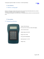
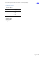
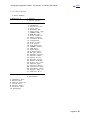
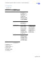
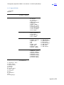
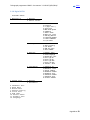
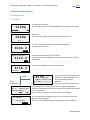
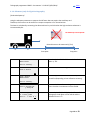
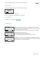
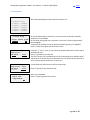
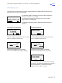
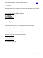
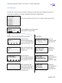
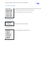
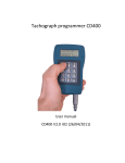
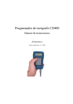
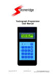
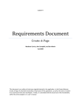
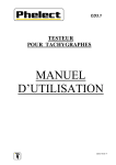
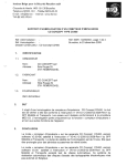
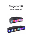
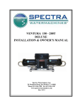
Tachograph programmer CD400
User manual
CD400 V2.0 r07 b10 (9/01/2014)
Tachograph programmer CD400 - User manual – V2.00 r07 (9/01/2014)
index
Index
1.
Introduction........................................................................................................................................................ 3
1.1.
2.
What is a tachograph?................................................................................................................................ 3
Description ......................................................................................................................................................... 3
2.1 Technical specifications .................................................................................................................................... 3
2.2. Keyboard ......................................................................................................................................................... 4
2.3. Connections ..................................................................................................................................................... 4
3.
Operation ........................................................................................................................................................... 5
3.1. Power supply and tachograph type detection ................................................................................................ 5
3.2. Menu trees ...................................................................................................................................................... 6
3.2.1. KTCO 13xx/1318 ....................................................................................................................................... 6
3.2.2. MTCO 1324/1390 ..................................................................................................................................... 6
3.2.3. Motomet.EGK100 ..................................................................................................................................... 7
3.2.4. Kienzle 1319 ............................................................................................................................................. 8
3.2.5. V.Root VR2400.......................................................................................................................................... 9
3.2.6. Digital VDO ............................................................................................................................................. 10
3.2.7. Digital SE5000 ......................................................................................................................................... 11
3.2.8. Digital ACTIA ........................................................................................................................................... 12
3.2.8. Digital EFAS ............................................................................................................................................. 13
4 Functions description ............................................................................................................................................ 14
4.1. Measure W .................................................................................................................................................... 14
4.1.1. Manual.................................................................................................................................................... 14
4.1.2. Photo Sensor .......................................................................................................................................... 15
4.1.3. Rolling road............................................................................................................................................. 15
4.1.4. Constant speed. ...................................................................................................................................... 15
4.1.5. Draw-wire. .............................................................................................................................................. 15
4.1.6. Odometer (only for digital tachographs)................................................................................................ 16
4.2 Measure K....................................................................................................................................................... 17
4.3. Parameters .................................................................................................................................................... 17
4.4. Speed test ...................................................................................................................................................... 17
4.4.1 Manual..................................................................................................................................................... 17
4.4.2 Automatic ................................................................................................................................................ 18
Page 1 sur 23
Tachograph programmer CD400 - User manual – V2.00 r07 (9/01/2014)
index
4.5. Odometer test ............................................................................................................................................... 19
4.6. Read DTCs ...................................................................................................................................................... 20
4.7. Erase DTCs ..................................................................................................................................................... 20
4.8. Sensor Pairing (Kitas activation) .................................................................................................................... 21
4.9. Clock test ....................................................................................................................................................... 21
4.10. PIN code ...................................................................................................................................................... 22
4.11. Select tachograph ........................................................................................................................................ 23
4.12. Product info ................................................................................................................................................. 23
4.13. Language ..................................................................................................................................................... 23
Page 2 sur 23
Tachograph programmer CD400 - User manual – V2.00 r07 (9/01/2014)
index
1. Introduction
1.1. What is a tachograph?
Basically, a tachograph is a device that measures and records the speed and distance driven by a vehicle.
The data are recorded in the form of graphics on a paper disk.
The new digital tachographs record those data on its embedded memory and also on the smartcard of the
driver.
2. Description
2.1 Technical specifications
- Graphic FSTF LCD Display:
100 x 32 px (4 lines x 20 char) - White LED backlight
- Size: 150 x 100 x 45 mm
- Supply voltage: 9 to 30 VDC
- Supply current: 12mA
- Case: green-blue ABS (IP40)
- Operating temp: -20…+70°C
- Weight: 155g
Page 3 sur 23
Tachograph programmer CD400 - User manual – V2.00 r07 (9/01/2014)
index
2.2. Keyboard
- Alternate function keys 'F1', 'F2' & 'F3' are active when a function in
inverted video appears on the bottom line of the display.
Trac k l eng th
0020m
MODI FY
OK
F1= MODIFY, F3=OK
- Alernate function key '↑' & '↓' are used for example to navigate the
menus.
- Alernate function key '←' & '→' are used to select the digit in some
parameters.
- 'Ent' (=Enter) is used to select a function or enter a value.
- 'Esc' key is used to go back in the menu, leave a function, to erase
the last digit entered and to switch the programmer ON & OFF when
powered by the battery.
2.3. Connections
- Left connector:
Serial port for software upgrade (upgrade cable).
- Center connector:
Connection for crocodile clip cable (K13xx/K1318).
- Right connector:
Connection for tachograph cable.
Page 4 sur 23
Tachograph programmer CD400 - User manual – V2.00 r07 (9/01/2014)
index
3. Operation
3.1. Power supply and tachograph type detection
For all tachograph types, except for the K13xx/1318 and the FTCO1319, the programmer is powered by the
tachograph itself. An automatic tachograph type detection is executed on power ON, so don't switch the
programmer ON, simply connect it to the tachograph with the appropriate cable. The programmer will switch
ON and detect the tachograph type.
In the case of the K13xx/1318 and the FTCO1319, switch the programmer ON pressing the 'I/O' key.
If the FTCO1319 is connected, the programmer will detect it.
To switch the programmer OFF, press and hold the 'I/O' key.
If no tachograph is detected, the K13xx/1318 will be selected by default.
On power ON, the programmer will display the product information (Software version, Serial number, etc...),
then the menu for the tachograph type detected.
Page 5 sur 23
Tachograph programmer CD400 - User manual – V2.00 r07 (9/01/2014)
index
3.2. Menu trees
The functions available in the main menu depend on tachograph model detected (or selected manually).
The tachograph model appears on the top line.
3.2.1. KTCO 13xx/1318
KTCO 13xx/1318
1.Measure W
1.Manual
2.Photo sensor
2.Measure K
3.Speed test
1.Manual
2.Automatic
4.Odometer test
5.Clock test
6.Select Tacho.
7.Product info.
8.Language.
3.2.2. MTCO 1324/1390
MTCO 1324/1390
1.Measure W
1.Manual
2.Photo sensor
2.Parameters
1.K Factor
2.Odometer
3.Instal. Date
4.Calibr. Date
5.Time & Date
6.O/P shaft
7.Service delay
8.CAN priority
9.Binary code
10.Product Code
11.VIN
12.N-RPM Factor
13.L-Tyre
14.Serial number
15.Maximum speed (1390 only)
3.Speed test
1.Manual
2.Automatic
4.Odometer test
5.Erase DTCS
6.Sensor pairing
7.Clock test
8.Select Tacho.
9.Product info.
10.Language.
Page 6 sur 23
Tachograph programmer CD400 - User manual – V2.00 r07 (9/01/2014)
index
3.2.3. Motomet.EGK100
Motomet.EGK100
1.Measure W
1.Manual
2.Photo sensor
2.Parameters
1.K Factor
2.Kn
3.U1
4.U2
5.U3
3.Speed test
1.Manual
2.Automatic
4.Odometer test
5.Select Tacho.
6.Product info.
7.Language.
Page 7 sur 23
Tachograph programmer CD400 - User manual – V2.00 r07 (9/01/2014)
index
3.2.4. Kienzle 1319
Kienzle 1319
1.Measure W
1.Manual
2.Photo sensor
2.Measure K
3.Parameters
1.K factor
2.Odometer
3.Instal. Date
4.Calibr. Date
5.Odometer Unit
6.Speed Warning
7.Fitter Number
8.Clock Speed
9.Kn ON/OFF
10.Kn Max
11.Kn Warning
12.Code
13.Mercedes ID
14.EEC Tacho.
15.SWISS ABZ
16.Driver change
17.4imp/m output
18.Note
19.Service
20.Tot. distance
21.Model
22.Serial number
23.Electronics
24.Code SO
25.Code ME
26.Code PR
4.Speed test
1.Manual
2.Automatic
5.Odometer test
6.Clock test
7.Select Tacho.
8.Product info.
9.Language.
Page 8 sur 23
Tachograph programmer CD400 - User manual – V2.00 r07 (9/01/2014)
index
3.2.5. V.Root VR2400
V.Root VR2400
1.Measure W
1.Manual
2.Photo sensor
2.Parameters
1.K factor
2.Odometer
3.Pulse per rev.
4.Idle rpm
5.Economy rpm
6.Poor Econ. rpm
7.CANBus RPM
8.RPM Display
9.Dist displ.0s
10.DTCs Display
11.Overspd Flash
12.Overspeed
12.Time & Date
13.O/P shaft
14.4th Chart Tr
15.CANBus enable
16.CAN Type
17.Dual Axle
18.D.Axle Ratio
19.D6 pin funct.
20.Speedo.OP fact
21.Serial Comms
22.Ignit.On rec.
23.Driver 2 Duty
24.Reset HeartBt
25.Eject pin code
26.Sensor type
27.Service Delay
28.Installat.date
29.Calibrat. date
30.Repair Shop ID
31.Vehicle ID n°
3.Speed test
1.Manual
2.Automatic
4.Odometer test
5.Erase DTCS
6.Sensor pairing
7.Clock test
8.Select Tacho.
9.Product info.
10.Language.
Page 9 sur 23
Tachograph programmer CD400 - User manual – V2.00 r07 (9/01/2014)
index
3.2.6. Digital VDO
DIGITAL VDO
1.Measure W
1.Manual
2.Photo sensor
2.Parameters
1.Calibration
1.W factor
2.K factor
3.L (Tyre Circ.)
4.Tyre Size
5.Max.Auth.Speed
6.Odometer
7.Time & Date
8.Next Cal. Date
9.Veh.Reg.Nation
10.Veh.Reg.Number
11.Veh.Id.Number
2.Other param.
1.ResetHeartbeat
2.TCO1 priority
3.O/P shaft
4.CAN rep.rate
3.Manufacturer
1.Part number
2.Drv1 ign.ON
3.Drv2 ign.ON
4.Drv1 ign.OFF
5.Drv2 ign.OFF
6.D1D2 Record
7.RPM Record
8.Speed Record
9.Install. date
10.ResetHeartbeat
11.CAN error
4.Information
1.Supplier Id
2.Manufact. Date
3.Serial number
4.Hardware number
5.Hardware vers.
6.Software number
7.Software vers.
8.License number
3.Speed test
12.CAN2 TC01 mess
13.CAN2 WakeUp D3
14.CAN2RemoteDown
15.RD interface
16.Speed Warning
17.Illum.mode
18.IMS Activation
19.IMS source
20.IMS factor
21.VDO Counter
1.Manual
2.Automatic
4.Odometer test
5.Read DTCS
6.Erase DTCS
7.Sensor pairing
8.Clock test
9.PIN code
10.Select Tacho.
11.Product info.
12.Language.
Page 10 sur 23
Tachograph programmer CD400 - User manual – V2.00 r07 (9/01/2014)
index
3.2.7. Digital SE5000
DIGITAL
SE5000
1.Measure W
1.Manual
2.Photo sensor
2.Parameters
1.Calibration
1.W factor
2.K factor
3.L (Tyre Circ.)
4.Tyre Size
5.Max.Auth.Speed
6.Odometer
7.Time & Date
8.Next Cal. Date
9.Veh.Reg.Nation
10.Veh.Reg.Number
11.Veh.Id.Number
12.O/P shaft
2.Other param.
1.ResetHeartbeat
2.TCO1 priority
3.O/P shaft
4.CAN rep.rate
5.Part number
3.Manufacturer
1.Part number
2.CanBus activat
3.Speed Corr.
4.D6
5.D4
6.Light input
7.RPM input
8.Default lang.
9.Serial Output
4.Information
1.Supplier Id
2.Manufact. Date
3.Serial number
4.Hardware number
5.Hardware vers.
6.Software number
7.Software vers.
8.License number
3.Speed test
10.D1D2 Record
11.RPM Record
12.Speed Record
13.Kn factor
14.Install.date
15.IMS Source
16.IMS Gain
17.IMS Factor
1.Manual
2.Automatic
4.Odometer test
5.Read DTCS
6.Erase DTCS
7.Sensor
pairing
8.Clock test
9.PIN code
10.Select
Tacho.
11.Product
info.
12.Language.
Page 11 sur 23
Tachograph programmer CD400 - User manual – V2.00 r07 (9/01/2014)
index
3.2.8. Digital ACTIA
DIGITAL ACTIA
1.Measure W
1.Manual
2.Photo sensor
2.Parameters
1.Calibration
1.W factor
2.K factor
3.L (Tyre Circ.)
4.Tyre Size
5.Max.Auth.Speed
6.Odometer
7.Time & Date
8.Next Cal. Date
9.Veh.Reg.Nation
10.Veh.Reg.Number
11.Veh.Id.Number
12.O/P shaft
2.Other param.
1.ResetHeartbeat
2.TCO1 priority
3.O/P shaft
4.CAN rep.rate
5.Part number
3.Specific
1.Default Lang
2.Card Language
3.Backlight conf.
4.Drv1 ign.ON
5.Drv2 ign.ON
6.Drv1 ign.OFF
7.Drv2 ign.OFF
8.Install. date
4.Information
1.Supplier Id
2.Manufact. Date
3.Serial number
4.Hardware number
5.Hardware vers.
6.Software number
7.Software vers.
8.License number
3.Speed test
1.Manual
2.Automatic
4.Odometer test
5.Read DTCS
6.Erase DTCS
7.Sensor pairing
8.Clock test
9.PIN code
10.Select Tacho.
11.Product info.
12.Language.
Page 12 sur 23
Tachograph programmer CD400 - User manual – V2.00 r07 (9/01/2014)
index
3.2.8. Digital EFAS
DIGITAL EFAS
1.Measure W
1.Manual
2.Photo sensor
2.Parameters
1.Calibration
1.W factor
2.K factor
3.L (Tyre Circ.)
4.Tyre Size
5.Max.Auth.Speed
6.Odometer
7.Time & Date
8.Next Cal. Date
9.Veh.Reg.Nation
10.Veh.Reg.Number
11.Veh.Id.Number
12.O/P shaft
2.Other param.
1.ResetHeartbeat
2.TCO1 priority
3.O/P shaft
4.CAN rep.rate
5.Part number
3.Specific
1.CAN-A activat.
2.CAN-A tr.rate
3.CAN-A ID mode
4.CAN-A sample
5.CAN-A pro.tach
6.CAN-A pro.diag
7.Trip Reset
8.ExtSerial act.
9.ExtSerial prot
10.Illumination
11.Engine Speed
4.Information
1.Supplier Id
2.Manufact. Date
3.Serial number
4.Hardware number
5.Hardware vers.
6.Software number
7.Software vers.
8.License number
3.Speed test
12.N Factor
13.EngSpdThreshold
14.SpeedThresholds
15.Lang.Handling
16.PrtLocalTimeEn
17.CAN-C activat.
18.CAN-C tr.rate
19.CAN-C ID mode
20.CAN-C sample
21.RemoteDataTrans
1.Manual
2.Automatic
4.Odometer test
5.Read DTCS
6.Erase DTCS
7.Sensor pairing
8.Clock test
9.PIN code
10.Select Tacho.
11.Product info.
12.Language.
Page 13 sur 23
Tachograph programmer CD400 - User manual – V2.00 r07 (9/01/2014)
index
4 Functions description
4.1. Measure W
4.1.1. Manual
1. Check the track length.
Press F3 (OK) to go on, or press F1(MODIFY) to change the track length.
Trac k l eng th
0020m
MODI FY
OK
Trac k l eng th
0020m
(optional)
to set the 'Track length', enter the new value and press 'Ent'.
[ 50 ]
Puls e c oun ter
0000.0
2. Press F3 (START) and drive the vehicule along the track.
The pulse count will start.
ST AR T
Puls e c oun ter
0123.0
3. At the end of the track, press F3 (STOP).
The W factor will be calculated as a function of the pulse count and the
track length.
S TO P
4. Press F3 (K FACTOR) to access K factor setting.
W fa cto r
6150.0
P:01 23. 0 K FA CT OR
K1318
Other
tachographs
K F A C T O R : 0 534 7p /km
NEW K:
0 534 7p /km
RECO RD NEW K ?
YES
NO
K Fac tor
K = 053 47p /km
MOD IF Y
W=
6150 p /k m
K TA BLE :06 147 p/ km
SWITCHES:1_3_5_7_9_
5. The closest value from the K factor
table of the 1318 is displayed with
the corresponding switches
positions.
Press 'Esc' to go back to main menu.
5. Present K factor will be read from the tachograph and displayed.
'NEW K' is the W factor that has been measured and should be recorded
as the new K factor.
Press F2 (YES) to record it or F3 (NO) to leave it unchanged.
6. If 'YES' has been selected previously, the new K factor will be read
back from the tachograph.
This factor can modified manually if required pressing F3 (MODIFY).
Page 14 sur 23
Tachograph programmer CD400 - User manual – V2.00 r07 (9/01/2014)
index
4.1.2. Photo Sensor
The W measure with a photosensor is exactely the same as in manual mode, except that the 'START' and 'STOP'
pulses are generated by the sensor. In photo sensor mode, the 'F3' (START & STOP) will not be active.
You can connect any photo sensor using a MiniDIN 4-pins connector connected to the left connector of the
CD400.
- Shielding: Ground (GND 0V).
- Pin n°2: photo sensor signal (the signal should be low when the reference
object/reflector is not detected).
4.1.3. Rolling road.
[Under development]
4.1.4. Constant speed.
[Under development]
4.1.5. Draw-wire.
[Under development]
Page 15 sur 23
Tachograph programmer CD400 - User manual – V2.00 r07 (9/01/2014)
index
4.1.6. Odometer (only for digital tachographs).
[Under development]
Using the odometer parameter to measure the W factor does not require the workshop card.
Therefore, this function can be useful for transport companies or for the authorities.
The latest is calculated by measuring the distance driven by a vehicle when the high resolution odometer is
incremented by 5m.
No workshop card required!
Driven distance to be measured (+/-5m)
Start point
Stop point
Drive slowly, the CD400 will detect the Start Point
within +/- 5m.
Star t P oin t
dete cti on
Driv e s low ly. ..
Mark the Start Point on the ground.
Mark
Star t P oin t
OK
Stop Po int
dete cti on
Drive slowly, the CD400 will detect the Stop Point in
around 5m (depending on last calibration accuracy).
Driv e s low ly. ..
Ente r d ist anc e:
[ 503 ]cm
K: 5 546 p/ km
W: 5 512 p/ km
Erro r: + 0 00. 6 %
OK
Measure the driven distance using a decameter and
enter the value in centimeter into the CD400.
As a result, the CD400 will display the K factor of the
tachograph, the W factor of the vehicle and the
calibration error in %.
Page 16 sur 23
Tachograph programmer CD400 - User manual – V2.00 r07 (9/01/2014)
index
4.2 Measure K
This function is available only for the K1314/1318 and the FTCO 1319.
Me asu re K
K:
0020 p /km
Measuring the K factor takes a few seconds.
The value is updated every time the progress bar is completed.
4.3. Parameters
The parameter list is available at: 3.2. Menu trees
4.4. Speed test
4.4.1 Manual
K Fac tor
K = 80 00 p/k m
MODI FY
OK
060.0 km/ h
K:8 000 p/ km
MODI FY
ON
060.0 km/ h
K:8 000 p/ km
MODI FY
OF F
For the K1314/1318 the K reference is set to the last K measured if available,
otherwize it is set to 8000. For the other tachographs the K reference is set to the
K factor programmed in the tachograph.
If required, the K reference can be adjusted manually pressing 'F1' (MODIFY).
By default the speed is set to 60 km/h.
Press F1 (ON/OFF) to start/stop speed simulation.
The text "km/h" is blinking when the speed is currently simulated.
Pressing the '↑' and '↓' keys, will increase/decrease the speed by 1km/h steps.
Pressing the '←' and '→' keys, will increase/decrease the speed by 0.1km/h steps.
Press F1(MODIFY) to insert a new speed value.
Page 17 sur 23
Tachograph programmer CD400 - User manual – V2.00 r07 (9/01/2014)
index
4.4.2 Automatic
Select diagram
→1.Custom
2.Tacho.
3.Tacho.
4.Tacho.
5.Tacho.
6.Tacho.
diag.
100km/h
125km/h
140km/h
160km/h
180km/h
Cu sto m d iag .
Kre f= 080 00 p/ km
MOD IFY
OK
Custom diag.
Step:01/23
180 km/h - 010s
EDI T
ST AR T
Custom diag.
Step:01/23 - 007s
180 km/h - 010s
K:05000
ST ART
Select the speed diagram to be executed and press 'Ent'.
For the K1314/1318 the K reference is set to the last K measured if available,
otherwize it is set to 8000.
For the other tachographs the K reference is set to the K factor programmed in
the tachograph.
If required, the K reference can be adjusted manually pressing 'F1' (MODIFY).
Press 'F3' (OK) if you agree with the K factor value.
Using the '↑' and '↓' keys, you can check the speed and duration of each step of
the automatic test.
Press 'F3' (START) to start the test.
The 'EDIT' funtion (F1) is available only for the custom diagram to edit the speed
and duration of current step of the automatic test. The automatic test will end at
the first step at which the duration is set to zero.
A count down will show the time left for present step.
Press 'F3' (STOP) to stop the bench test
Bench test completed.
Press 'F3' (OK) to go back to the menu.
Custom diag.
Bench test
Compleleted
OK
Page 18 sur 23
Tachograph programmer CD400 - User manual – V2.00 r07 (9/01/2014)
index
4.5. Odometer test
The programmer will automatically simulate a speed of 50km/h on 1000m distance and check if the
odometer as been incremented by 1000m.
Od ome ter te st
Kre f= 080 00 p/ km
MOD IFY
OK
For the K1314/1318 the K reference is set to the last K measured if
available, otherwize it is set to 8000.
For the other tachographs the K reference is set to the K factor
programmed in the tachograph.
If required, the K reference can be adjusted manually pressing 'F1'
(MODIFY).
KTCO1318/FTCO1319/EGK100
Odom ete r t est
1000 m
+
S TA RT
Press 'F2' to adjust the position of the start point.
Press 'F3' (START) to start the test.
Odometer test
0
1000m
MTCO/VR2400/DIGITAL
Odom ete r t est
D1:0041728740m
S TAR T
The inital value of the odometer (D1) will be read.
Press 'F3' (START) to start the test.
Odom ete r t est
D1:0041728740m
S TO P
S TO P
Wait until the progress bar is completed.
The test can be aborded pressing 'F3' (STOP).
Wait until the progress bar is completed.
The test can be aborded pressing 'F3' (STOP).
Odom ete r t est
D1:0041728740m
D2:0041729740m
(-) 100 0m
OK
At the end of the test, the final odometer value will
be read (D2). The difference between D2 and D1 will
be calculated (D2-D1). If the difference equals
1000m, the test has been successful.
Page 19 sur 23
Tachograph programmer CD400 - User manual – V2.00 r07 (9/01/2014)
index
4.6. Read DTCs
The function "Read DTCs" is used to read the "Diagnostic Trouble Codes" (DTC) stored in the error memory of
the tachograph.
It is available for the following tachographs:
- Digital tachographs (DTCO1381, SE5000, SmarTach & EFAS)
DTCs number:03
01: 002452 (2F)
SensorTachograph
SignatureMismatch23
DTCs number is the error number available in memory
Error code
Full error description
Use the '↑' and '↓' keys to select next or previous error.
Press 'Esc' to go back to main menu.
4.7. Erase DTCs
The function "Erase DTCs" is used to erase the "Diagnostic Trouble Codes" (DTC) stored in the
error memory of the tachograph.
It is available for the following tachographs:
- MTCO 1324/1390
- VR2400
- Digital tachographs (DTCO1381, SE5000, SmarTach & EFAS)
The following message is displayed after erasing the error memory.
Erase DTCs
erased
successfully
Press 'Esc' to go back to main menu.
Page 20 sur 23
Tachograph programmer CD400 - User manual – V2.00 r07 (9/01/2014)
index
4.8. Sensor Pairing (Kitas activation)
This function is available for the following tachographs:
- MTCO 1324/1390
- VR2400
- Digital tachographs (DTCO1381, SE5000, SmarTach & EFAS)
Sensor pairing is executed automatically after modifying any calibration parameter on digital tachographs.
Sensor pairing
A progress bar indicates the status of KITAS
activation.
Sens or pai rin g
> S ucc ess ful l
OK
Kistas sensor is activated with success.
Sens or pai rin g
> ER ROR !
OK
No response received from KITAS.
4.9. Clock test
The clock test function will check the accuracy of the clock of the tachograph.
For the K1314, the K1318 and the k1319, an external clock sensor has to be used.
Cl ock te st
000 s/d ay
The measure is updated every second.
The result represents the clock deviation in seconds/day.
Press 'Esc' to go back to main menu.
Page 21 sur 23
Tachograph programmer CD400 - User manual – V2.00 r07 (9/01/2014)
index
4.10. PIN code
The "PIN code" function permits to send the workshop card PIN code to the tachograph automatically.
This function is available for the Digital tachographs (DTCO1381, SE5000 & EFAS)
PIN code
Select the workshop card ID in the list (ie: name of owner) and press 'Ent'.
→1.Card 1
2.Card
3.Card
4.Card
5.Card
2
3
4
5
PI N c ode
Card 1
#6 PIN:******
MOD IFY
Press F1(MODIFY) to modify the data.
Press F3(Ok) to send the code.
OK
MODIFY (card name, PIN code & protection code).
PI N c ode
Card 1
^
0
A
M
'↓' keys. Then press 'Ent'.
Edit the card id.
Select the digit using the
'←' & '→' keys and set the
digit value using the '↑' &
Adjust the PIN code length
using the '↑' and '↓' keys
and press 'Ent'.
PI N c ode
Card 1
#6
^
OK (send data).
PI N c ode
Prot ect ion co de :
(** **)
Enter the
protection code
and press 'Ent'
PIN code
PIN code sent
Check tacho.
Response 1.
PIN code has
been sent.
Check Tachograph.
PI N c ode
#6 PIN:D00000
^
0
A
keys. Then press 'Ent'.
M
Edit the PIN code.
Select the digit using the '←'
& '→' keys and set the digit
value using the '↑' & '↓'
Enter a protection code
which will be required to be
able to send the PIN code.
The code can be from 1 to 4
digits long or can be left blank if not necessary.
PI N c ode
Prot ect ion co de :
(** **)
PIN code
TCO already in
Calibration mode
No PIN code required.
PIN code
Conditions
not correct
code (i.e. no card inserted).
Response 2.
The tachograph is
already in
calibration mode.
Response 3.
The tachograph is
not ready to
receive the PIN
Page 22 sur 23
Tachograph programmer CD400 - User manual – V2.00 r07 (9/01/2014)
index
4.11. Select tachograph
Select Tacho.
→1.KTCO 13xx/1318
2.MTCO1324/1390
3.Motomet.EGK100
4.Kienzle 1319
5.V.Root VR2400
6.Digital VDO
7.Digital SE5000
8.Digital Actia
9.Digital EFAS
The tachograph type is detected automatically on power ON, but if for any reason,
another type has to be selected, this can be done manually.
Select the tachograph type in the menu and press 'Ent'.
4.12. Product info
CD400 Programmer
Sn: 56000010
SW: V2.0 r07
www.cdconcept.be
Shows software version and serial number.
4.13. Language
Language
→1.English
2.Deutsch
3.Español
4.Français
5.Nederlands
6.Português
7.Turkish
8.Romanian
9.Russian
Select the language in the menu and press 'Ent'.