1
General
Specifications
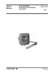
Model FLXA21
2-Wire Analyzer
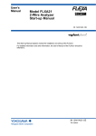
The model FLXA21® two-wire analyzer is used for continuous
on-line measurements in industrial installations. It offers an option
for single or dual sensor measurement, making it the most
flexible 2-wire analyzer available. The model FLEXA21® modulardesigned series analyzer offers 4 parameter choices – pH/ORP
(oxidation-reduction potential), contacting conductivity (SC),
inductive conductivity (ISC) or dissolved oxygen (DO) – with the
respective sensor module.
For dual sensor measurement, the sensor modules must be
the same parameter – pH/ORP and pH/ORP, SC and SC,
and DO and DO. Dual sensor measurement offers additional
functionalities including a variety of calculated data from the
two measuring parameters, as well as, the option to program
the analyzer as a redundant system. In the redundant system
the main output parameter is automatically switched over to the
second sensor output in case of the main sensor’s failure. ISC is
only available as a single measurement.
When the analyzer is initially powered on the FLXA21®
automatically recognizes the installed sensor module and initiates
Quick Start menus for fast easy start up. Only a few setups;
date/time, language, basic sensor configurations and output, are
needed to start the measurement.
The FLXA21® incorporates the same unique Human Machine
Interface (HMI) as seen in the EXA450 series; offering easy touch
screen operation and a simple intuitive menu structure available
in 12 different selectable languages.
The FLXA21® provides industry proven measurement accuracy
incorporating essential temperature compensation and calibration
functionalities, with advanced self-diagnostics and sensor
wellness indication to provide a highly reliable measurement.
The logbook of events and diagnostic data provided are useful
information sources for preventive maintenance.
Yokogawa designed the FLXA21® to withstand a wide range
of industrial environments. The FLXA21® is housed in a robust
NEMA 4X, IP66 mountable enclosure, and meets all the CE
regulatory standards. It is designed to have the option for
enclosure housing selection to meet specific industry needs:
poly carbonate, stainless steel or stainless steel with corrosion
resistant coating.
Features
•O
ne analyzer can accept any of 4 types of measurements; pH/
ORP, Contacting Conductivity (SC), Inductive Conductivity (ISC)
and Dissolved Oxygen (DO)
• Dual sensor measurement on a 2-wire type analyzer pH/ORP
and pH/ORP, SC and SC, and DO and DO
• Modular design: replaceable sensor modules
• Redundant system on dual sensor measurement
• Intuitive easy touch screen operation on 2-wire type analyzer
• Unique HMI menu structure in 11 languages (Polish pending)
• Quick setup menu for fast and east measurement operation
• Online Sensor Wellness checking for predictive maintenance
• NEMA 4X / IP66 Enclosure
GS 12A01A02-01E-E
2nd Edition
2
General Specifications
Performance (Accuracy)
(The specifications are expressed with simulated inputs.)
Basic
pH
Linearity
Repeatability
Accuracy
:±
0.01 pH
: ±0.01 pH
: ±0.01 pH
ORP
Linearity
Repeatability
Accuracy
:±
1 mV
: ±1 mV
: ±1 mV
Measurement Parameter
The FLXA21® can be configured to measure:
• pH/Oxidation-reduction Potential (pH/ORP)
• Contacting Conductivity (SC)
• Inductive Conductivity (ISC)
• Dissolved Oxygen (DO)
Note: T
he available measurement parameter depends on a
sensor module installed in the analyzer.
Analyzer Structure
Module structure
Composition of Analyzer
One (1) Base module General Purpose
• CSA, FM, ATEX, (pending)
• FOUNDATION Fieldbus, (pending)
• PROFIBUS (pending)
One (1) or two (2) Sensor modules inputs
The FLXA21® supports up to two sensors of the same type,
thereby reducing installation costs.
Allowable combinations when two modules are installed are:
• pH/ORP and pH/ORP
• SC and SC
• DO and DO
pH/Redox Potential (pH/ORP)
Input Specification
Dual high impedance input (≥1012 Ω), compatible with all
Yokogawa pH/ORP sensors and most competitor electrodes.
Temperature:
Pt1000
Pt100
6k8
PTC10k
NTC 8k55
3k Balco
PTC500
with Pt100
Linearity
Repeatability
Accuracy
Calibration
Semi-automatic 1 or 2 point calibration using pre configured
NIST, US, DIN buffer tables 4, 7 & 9, or with user defined buffer
tables, with automatic stability check; or Manual adjustment to
grab sample.
Input Range
Conductivity
: - 2 to 16 pH
: -1500 to 1500 mV
: 0 to 100 rH
:
:
:
:
:
:
:
-30
-30
-30
-30
-10
-30
-30
to
to
to
to
to
to
to
140
140
140
140
120
140
140
°C
°C
°C
°C
°C
°C
°C
(-22
(-22
(-22
(-22
(-22
(-22
(-22
Input Specification
Two or four electrode measurement with square wave excitation.
Any cell constant from 0.005 to 50.0 cm-1 can be used.
Influence of cable can be adjusted by doing an AIR CAL with the
cable connected to a dry cell.
to
to
to
to
to
to
to
284°F)
284°F)
284°F)
284°F)
284°F)
284°F)
284°F)
Resistivity
Temperature:
Pt1000
Pt100
Ni100
NTC 8k55
Pb36(JIS NTC 6k)
Cable length
Cable length
Output Range
pH
ORP
rH
Temperature
:±
0.4 ºC
: ±0.1 ºC
: ±0.4 ºC
Conductivity (SC)
Measurement
Input Range
pH
ORP
rH
Temperature
(with Pt1000, 6k8, PTC10k, NTC 8k55, 3k Balco, PTC500)
Linearity
: ±0.3 ºC
Repeatability
: ±0.1 ºC
Accuracy
: ±0.3 ºC
:6
0 meters (196 feet) from the sensor
to the analyzer
:
:
:
:
:
:
:
:
GS 12A01A02-01E-E
min. Span 1 pH
max. Span 20 pH
min. Span 100 mV
max. Span 3000 mV
min. Span 2 rH
max. Span 100 rH
min. Span 25 ºC
max. Span 200 ºC
(for 8.55kV NTC sensor max. 120 ºC)
Output Range
Conductivity
Resistivity
Temperature
:m
in. 0 µS/cm
: max. 200 mS x Cell constant
(over range 2000 mS/cm)
: min. 0.005 kΩ / Cell constant
: max. 1000 MΩ x cm
:
:
:
:
:
- 20
-20
-20
-10
-20
to
to
to
to
to
250
200
200
120
120
ºC
ºC
ºC
ºC
ºC
(-4 to 482°F)
(-4 to 392°F)
(-4 to 392°F)
(14 to 248°F)
(-4 to 248°F)
:6
0 meters (196 feet) from the sensor
to the analyzer. Influence of cable can
be adjusted by doing an AIR CAL
with the cable connected
to a dry cell.
:m
in. 0.01 µS/cm
: max. 2000 mS/cm
(max 90% zero suppression)
: min. 0.001 kΩ x cm
: max. 1000 MΩ x cm
(max 90% zero suppression)
: min. 25 ºC (77°F)
: max. 200 ºC (392°F) (for NTC 8k55
sensor max. 120 ºC (248°F))
3
Performance (Accuracy)
(The specifications are expressed with simulated inputs.)
Conductivity
2 µS x CC to 200 mS x CC
Accuracy
: ±0.5%F.S.
1 µS x CC to 2 µS x CC
Accuracy
:±
1%F.S.
Resistivity
0.005kΩ / CC to 0.5MΩ /CC
Accuracy
:±
0.5%F.S.
0.5MΩ / CC to 1MΩ /CC
Accuracy
: ±1%F.S.
Temperature
with Pt1000, Pb36, Ni100
Accuracy
: ±0.3 ºC
with Pt100, NTC 8k55
Accuracy
: ±0.4 ºC
Temperature compensation
NaCl table
: ±1 %
Matrix
: ±3 %
Note: “ F.S.” means maximum setting value of analyzer output.
“CC” means Cell Constant. YOKOGAWA provides
conductivity sensors of which cell constants are
0.01 to 10 cm-1.
Calibration Semi-automatic calibration using pre-configured
OIML (KCl) buffer tables with automatic stability check, or Manual
adjustment to grab sample
Inductive Conductivity (ISC)
Input Specification
Compatible with the Yokogawa inductive conductivity ISC40
series with integrated temperature sensor: NTC30k or Pt1000.
Performance (Accuracy)
(The specifications are expressed with simulated inputs.)
(Output span is 0-100 µS/cm or more)
Conductivity:
Linearity
Repeatability
:±
(0.4 %F.S. + 0.3 µS/cm)
: ±(0.4 %F.S. + 0.3 µS/cm)
Temperature
: Accuracy: ±0.3 ºC
Note: “F.S.” means maximum setting value of analyzer output.
Calibration
Semi-automatic calibration using pre-configured OIML (KCl)
buffer tables with automatic stability check, or Manual adjustment
to grab sample
Dissolved Oxygen (DO)
Input Specification
The FLXA21 accepts output from membrane covered Dissolved
Oxygen sensors. These sensors can be Galvanic type, where
the sensor generates its own driving voltage, Polarographic
type, where the sensor uses external driving voltage from the
transmitter, or Optical sensor where luminiscent technology is
utilized.
The input range is 0 to 50 µA for Galvanic sensors, 0 to 1 micro
A for Polarographic sensors and Optical sensors.
For temperature compensation, the FLXA21 accepts Pt1000
(DO30G and Visiferm sensor) and NTC22k elements (OXYFERM,
OXYSENS and OXYGOLD sensors).
Input Range Output Range
DO30G sensor Input:
Dissolved Oxygen
: 0 to 50 mg/l (ppm)
DO30G Sensor Output:
DO concentration
% saturation
: min.: 1 mg/1 (ppm)
: max.: 50 mg/1 (ppm)
: min.: 10%
Input Range
Conductivity
min.
max.
:0
to 2000 mS/cm at 25 ºC (77°F)
: 0 μS/cm (at process temperature)
: 2 S/cm (at process temperature)
Cable length
Temperature
: -20 to 140 ºC
Cable length
:m
ax. 60 meters (196 feet) total length
of the fixed sensor cable + WF10
extension cable. Influence of cable
can be adjusted by doing an AIR CAL
with the cable connected
to a dry cell.
Hamilton™ Sensors Input and Output:
OXYFERM:
Measurement range : 10 ppb to saturation or
0.1 % - 200% of air oxygen
Temperature range
: 0 to 130 ºC (32 to 266˚F)
OXYSENS:
Measurement range : 40 ppb to saturation
Temperature range
: 0 to 60°C (32 to 140°F)
OXYGOLD G:
Measurement range : 1 ppb to saturation or
0.012 % - 200% of air oxygen
Temperature range
: 0 to 130 °C (32 to 266°F)
OXYGOLD B:
Measurement range : 8 ppb to saturation or
0.1 % - 200% of air oxygen
Temperature range
: 0 to 100 °C (32 to 212°F)
VISIFERM:
Measurement range : 4 ppb to 40 ppm
Temperature range
: 0 to 130°C (32 to 266°F)
Output Range
Conductivity
Temperature
: min. span 100 µS/cm
: max. span 2000 mS/cm
(max 90% zero suppression)
: min. 25 ºC
: max. 200 ºC
:m
ax. 60 meters (196 feet) total length
of the fixed sensor cable + WF10
extension cable.
GS 12A01A02-01E-E
4
Performance in ppm mode:
Linearity
: ±0.05
ppm or ±0.8% F.S.,
whichever is greater
Repeatability
: ±0.05 ppm or ±0.8% F.S.,
whichever is greater
Accuracy
: ±0.05 ppm or ±0.8% F.S.,
whichever is greater
Performance in ppb mode:
Linearity
: ±1
ppb or ±0.8% F.S.,
whichever is greater
Repeatability
: ±1 ppb or ±0.8% F.S.,
whichever is greater
Accuracy
: ±1 ppb or ±0.8% F.S.,
whichever is greater
Temperature
Linearity
Repeatability
Accuracy
:±
0.3 ºC
: ±0.1 ºC
: ±0.3 ºC
Electrical
Output Signal
FOUNDATION Fieldbus and PROFIBUS-PA (Pending)
:O
ne 4-20 mA DC loop powered output
Note: Tolerance ±0.02 mA
: Bi-directional HART digital
communication, superimposed on
mA (4-20mA) signal
Output function
: Linear or Non-linear (21-step table)
Burn out function
: (NAMUR 43)
Without HART/PH201G:
Down
: 3.6 mA (signal: 3.8 to 20.5 mA for
pH/ORP, SC and DO)
(signal: 3.9 to 20.5 mA for ISC)
Up
: 22mA
With HART:
Down
Down
Up
: 3.6 mA for pH/ORP, SC and DO
: 3.9 mA for ISC
(signal: 3.8 to 20.5 mA for pH/ORP,
SC and DO)
(signal: 3.9 to 20.5 mA for ISC)
: 22mA
Power Supply
Nominal 24 V DC loop powered system
One (1) Sensor module (1 input)
: 16 to 40V DC (for pH/ORP, SC & DO)
: 17 to 40V DC (for ISC)
Two (2) Sensor modules (2 inputs)
: 22.8 to 40V DC (for pH/ORP, SC & DO)
GS 12A01A02-01E-E
2-sensor measurement
1295
R=
1000
600
Except ISC
V - 11.5
0.022
Digital Communication
Range (HART)
304
250
0
Note: “F.S.” means maximum setting value of analyzer output.
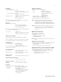
General
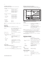
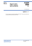
Maximum Load Resistance (Figure 1)
The FLEXA21® will not start-up below 16V and the load
resistance has to be above 250 ohm, the HART communication
will only work above 18.2VDC and 304 ohm load (max 600 ohm).
Load resistance (Ω)
Performance (Accuracy)
(The specifications are expressed with simulated inputs.)
1617 18
22.8 24.7
18.2
Voltage (V)
40
Supply Supply Voltage and Load Resistance
Display
LCD with a touch screen : Black/White:
213 x 160 pixels
Contrast adjustment available on the
touch screen
Message language
: 11 (English, Japanese, Chinese,
Korean, German, Portuguese,
Russian, Spanish, French, Italian and
Czech, (Polish pending))
: One analyzer has all 11 languages.
Note: O
n a language selection screen, its title and description
and its menu of languages are described in English.
Note: Only English alphabet and numeric are available for a tag
number and an additional description for each value on
the display screen and passwords.
Note: Only for message language on the screen, 11 languages
are provided.
Mechanical and others
Housing Options Available
Case
: Polycarbonate
: Stainless steel without painting
: Stainless steel with epoxy coating
: Stainless steel with urethane coating
Case color and finish:
Color
: Silver gray (equivalent to Munsell
3.2PB7.4/1.2) (for poly carbonate
case, stainless steel cases with
coating)
Finish
: Electropolishing (for stainless steel
case without painting)
Window
: Polycarbonate (flexible)
Protection
: NEMA4X, IP66
Plate
Main name plate
Regulation plate
: inside case cover
: on the case outside
Cable and Terminal
Cable Size Requirements (Not Provided)
Outer diameter
: 6 to 12 mm
(suitable for M20 cable gland)
: 3.4 to 7 mm
(grounding cable for poly carbonate
case)
Terminal screw size
: M4
5
Cable Entry
Polycarbonate case:
1-Sensor measurement:
:
:
2-Sensor measurement:
:
:
Stainless steel case
:
:
:
3 holes,
M20 cable gland x 3 pcs,
Sleeve x 1 pc (for grounding cable line)
4 holes,
M20 cable gland x 4 pcs,
Sleeve x 1 pc (for grounding cable line)
7 holes,
M20 cable gland x 7 pcs
Close up plug x 5 pcs
Note: C
able gland and plug are delivered with an analyzer, but
not assembled into the analyzer.
Mounting
Mounting hardware (option):
: Universal mounting kit (Note)
: Pipe and wall mounting hardware
: Panel mounting hardware
Note: T
his kit contains the pipe and wall mounting hardware and
the panel mounting hardware.
Hood (option)
: Stainless steel
: Stainless steel with urethane coating
: Stainless steel with epoxy coating
Stainless Steel Tag Plate
Regulatory Compliance
ATEX (and CSA/FM Pending)
Safety
: EN61010-1
: CSA C22.2 N.61010-1
EMC
: EN61326-1 Class A,Table 2
(For use in industrial locations)
: EN61326-2-3
: AS/NZS CISPR11
Installation altitude
: 2000 m or less
Category based on IEC 61010: I (Note 1)
Pollution degree based on IEC 61010: 2 (Note 2)
Note 1: Installation category, called over-voltage category,
specifies impulse withstand voltage. Equipment
with “Category I” (ex. 2-Wire transmitter) is used for
connection to circuits in which measures are taken to
limit transient over-voltages to an appropriately low level.
Note 2: P
ollution degree indicates the degree of existence of
solid, liquid, gas or other inclusions which may reduce
dielectric strength. Degree 2 is the normal indoor
environment.
Digital Communication
Type of Digital Communication
• HART
• FOUNDATION Fieldbus (Pending)
• PROFIBUS (Pending)
Blank tag plate is hanging type (delivered with an analyzer).
When the additional code “/SCT” and a tag number is specified,
the specified tag number is inscribed. (Inscription is optional.)
Conduit Adapter
Using optional adapter : G1/2 (quantity: 4)
: 1/2NPT (quantity: 4)
: M20 x 1.5(quantity: 4)
These conduit adapters are delivered with an analyzer, but not
assembled into the analyzer.
Size of Housing Case
Poly carbonate
Stainless steel case
Shipping Details
Package size
:1
44 x 144 x 151 mm (L x W x D)
(without cable gland)
: 165 x 165 x 160.1 mm (L x W x D)
(without cable gland)
Note: O
nly one kind of digital communication is available for one
analyzer.
Output Value Parameter (HART)
Four value parameters are available for one digital communication.
For 1-sensor measurement, these parameters are
measured values.
For 2-sensor measurement, refer to the next item.
Digital Communication of 2-Sensor Measurement (HART)
Even when two sensor modules are installed, only one digital
communication is available for 2-sensor measurement.
Four value parameters can be selected from the followings;
Measured values of two sensors
Calculated data of 2-sensor measurement
Redundant system output
: App. 340 x 340 x 370 mm (L x W x H)
Ambient Operating Temperature
: -20 to +55 ºC (-4 to 131°F)
Storage Temperature : -30 to +70 ºC (-22 to 158°F)
Humidity
: 10 to 95% RH (Non-condensing)
Document
Following documents are delivered with an analyzer;
Paper copy
: Start-up Manual written in English
CD-ROM
:S
tart-up Manual (pdf) written
in 12 languages
: User’s Manual (pdf) written in English
: Safety Regulation Manual (pdf) for
European region written
in 25 languages
GS 12A01A02-01E-E
6
Features of FLEXA
Sensor Calculation
For pH + pH
For DO + DO
Differential
Average
Sensor Calculation
For SC + SC*
Ratio
Average
Differential
Passage[%]
Rejection[%]
Deviation[%]
pH calc.
Software
(input1) - (input2)
(input1 + input2) / 2
(input1) / (input2)
(input1 + input2) / 2
(input1) - (input2)
(input2) / (input1) X 100
(input1 - input2) / (input1) X 100
(input2 – input1) / (input1) X 100
(VGB) pH=8.6+log{(input1) - (input2)/3}
Note: for resistivity, only differential and average can be selected.
PROFIBUS-PA Communications (Pending)
Input signal
: Digital
Supply voltage
: 9 to 32 V DC
Operating current
: 26.0 mA (pH) and 24.5 mA SC, ISC,
and DO
Operating values
: According to IEC 1158-2
Bus connection
: Fieldbus interface based on IEC
1158-2 according to FISCO-Model
Power supply
: Power supply is achieved dependant
on the application by means of
segment coupler
Data transfer
: According to PROFIBUS- PA profile
class B based on EN 50170 andDisplay
DIN
19245 part 4
GSD file
: The actual file can be downloaded
Sensor 1
from www.profibus.com
Configuration
: Local with 6 keys
Software
: Firmware based on Siemens DPC31
stack.
Hardware
: PC- or PCMCIA-interfaces from
Siemens
Sensor 2
R(1)
Display
Other control
: Siemens PDM systems
Electrical connection : Terminals acc. to IEC 1158-2
Alive
Fieldbus-cable-types : Twisted and shielded
two wire cable
Sensor 1
according to recommendation based
mA
on IEC 1158-2
Cable diameter
: 6 to 12 mm (0.24 to 0.47 inch)
Alive
Sensor 2
:N
ational Instruments, NI-FBUS
configurator
Hardware
: FBUS-interfaces from National
Instruments (AT-FBUS and PCMCIA
FBUS)
Other control systems : Yokogawa PRM, DMT
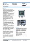
Redundancy
A Variety of calculated data from two measuring parameters
is selectable for each measurement. The redundant system is
a function of backing up the 1st module with the 2nd module.
This function is designed such that under normal conditions, the
sensor-1 pH value is the current output and if the sensor 1 fails,
the sensor-2 pH value is the current output.
Time
Sensor 1 operative
Sensor 1 Fails
Sensor 1
Alive
mA output
Sensor 2
Alive
Fail
Alive
Repair sensor 1
Alive
mA output
Automatically switch
to sensor 2
Switch back to sensor 1
manually
Alive
Alive
mA output
Example 1: sensor failure
Time
Sensor 1
Alive
mA output
Sensor 2
R(1)
Alive
Sensor 1 in calibration
R(1)
Display
End
Start
Calibration
Alive
Sensor 1
Sensor 1 operative
R(2)
Alive
mA output Dead
back to sensor 1
Intentionally switch
mA Switch
manually
to sensor 2
Alive
mA output
R(2)
Alive
Sensor 2
Example
Alive 2: sensor calibration
Dead
Repair sensor
Dead
Alive
Alive
Repair sensor Alive
Dead
mA
Alive
mA 1 fails, the output is automatically
If sensor
switched to the
Sensor 1 is dead.
sensor-2 value.
(automatic)
redundant restart (ma
Even if a failure on the sensor 1 is recovered automatically
Alive
Alive
after failure detection, the output will not be switched back
R(2)
R(1)
automatically and the
sensor 2 value mA
will continue to be output.
Repair sensor
Dead
Alive
After Dead
repairing sensor 1,
Output setup
Res
Sensor 1 is dead.
redundant system
Alive
reset the backup made
mA Output mA
Return m
(automatic)
restart (manual)
by the
redundant system.
This enables the sensor 1
value to be incorporated
Alive
Alive
in the output.On the
mAsystem,
FOUNDATION Fieldbus H1 Communications (Pending)
Reset redundant
Configure Hold
Input signal
: Digital
selection of “Yes” makes
Sensor 1 is dead.
redundant system
Reset redundant
Yes
Supply voltage
: 9 to 32 V DC
the output return to the
(automatic)
restart (manual)
No
Operating current
: 26.0 mA (pH) and 24.5 mA SC, ISC,
output ofOutput setup
the 1st module.
Reset redundant syst
and DO
mA Output
Return mA to Sensor1?
Operating values
: According to IEC 1158-2
This display is the
Bus connection
: Fieldbus interface based on IEC
example when
1158-2 according to FISCO-Model
“Redundant” is selected
Power supply
: Power supply is achieved dependant
as a process parameter.
Output setup
Reset redundant system
on the application by means of
mA Output
Return mA to Sensor1?
segment coupler
Data transfer
: FF Specification Rev. 1.4, Basic
Configure Hold
device
Reset redundant
Yes
Function blocks
: 3xAI, Transducer, Resource
No
Files
: Actual file can be downloaded from
our homepage
Configure Hold
Configuration
: Local with 6 keys,
Reset redundant
Yes
Example 2: Calibration No
GS 12A01A02-01E-E
7
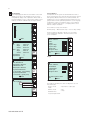
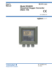
Display and Operating Interface
1
Fail:
Temperature too high
The Display is a Black/White LCD touch screen. FLXA21® uses
the same unique Human Machine Interface (HMI) as seen in the
EXA450 series, offering easy touch screen operation and simple
menu structure. Graphical keys on the right and other areas of
the touch screen respond to contact as virtual push buttons.
(Figures below show a conductivity and pH measurement, and
the value will reflect the sensor modules installed in the FLXA21®)
Warn:
No warn
Enter
1 Tag: FLXA21-PH
24.7
ºC
2 Tag: FLXA21-PH
64.2
ºC
4mA
PH1
pH
6.28
1
Measured process
temperature exceeds
maximum limit.
Remedy
Check process temperature.
Check programmed sensor
type. Check connections and
cable
pH
4.28
20mA
Enter
Home Display
Home Display appears upon startup when two sensor modules
are connected. (Home display is not available when only one
sensor is connected)
6.28
Trend
Screen
Trend Screen appears when the primary value on the main
display is pressed, or when the Trend button( ), on the
Zoom display is pressed.
1 Tag: FLXA21-PH
4mA
PH1
20mA
Main Display
Main Display appears upon startup when one sensor module is
connected. When a FLEXA21® has two sensor modules in the
unit, selecting Sensor 1 or Sensor 2 on the home display brings
up the main display of the selected sensor.
Status
screen
Status screen or Information button( ), gives access
to diagnostic information with regard to the analyzer or
sensors.
No
malfunction detected
Warning
When a warning indicator appears, maintenance is
required. Pressing this key displays the detected
malfunction code, and pressing the malfunction codes
displays troubleshooting guide lines for resolving the
malfunction.
;
Fail
Indicates malfunction. Pressing this key displays the
detected malfunction code, and pressing the malfunction
codes displays troubleshooting guidelines for resolving the
malfunction.
12.00
Measurement value
pH
24.7 ºC
Tag: FLXA21-PH
C
D
9-10pH
pH1
F
Maximum
Live reading
8.40
5.60
Minimum
G
2.50
12.00
B
12.20
12.40
Time
A
E
Maximum
Average
Minimum
A: X axis S
how the Time scale
(user programmable from 15 minutes to 14 days)
B: Y axis Measurement value axis user (programmable)
C: Tag No.
D: Current measurement value with unit
E: Trend (maximum, minimum and average values during the
display update time)
F: Icon (current measurement value, and maximum and
minimum values until the display update)
G: Warn/Fail indicators (indicated only during Warn/Fail status)
Maintenance
screen (Execute & Setup) appears when
the commissioning button is pressed. The maintenance
screen gives access to calibration, commissioning and
configuration of the instrument. These operations can be
protected by passwords.
1
Execute & Setup
Execute:
Calibration/Wash
Hold
Temporary output
Setup:
Commisioning
Change language
Start Quick Setup
Enter
GS 12A01A02-01E-E
8
Zoom
Display
Zoom Display appears when the Zoom button on the main
display is pressed. The Zoom display shows an easy-toread graphical display of the output status. When “Next” is
pressed it will give access to current sensor settings, sensor
wellness, last known calibration data, and log book data.
mA
Sensor Wellness
It is important that the system be well maintained to make a
precise measurement. The electrodes must be properly cleaned
and regularly calibrated. At the Sensor wellness window, the
healthiness of a sensor is displayed. A larger number of in each
gauge indicates that the particular parameter is sound. A gauge
is indicated for only those parameters whose sensor wellness
setting is “enabled,” while a bar (—) is displayed if the sensor
wellness setting is “disabled.”
20
Sensor wellness setup can be made in
Commissioning — Measurement setup — Sensor diag. settings.
12
The Reset wellness data button allows you to reset data
except temperature calibration. This is done when a new
sensor is installed.
4
15.00
Enter
Next
1
pH:
Zero
Slope
Sensor
ORP: Zero
Slope
Sensor
Impedance1
Impedance2
0.000
0.000
50.00
0.000
0.000
0.000
------Next
mV
%
mV
mV
%
mV
1 2010/10/15 17:04:07
Last calibrated at
2020/09/08 08:00:00
Calibration due at
2020/10/08 08:00:00
Projected maintenace
6-12 months (no meaning)
Projected replacement
3-6 months (good pred.)
Next
Enter
Enter
For pH
1
Sensor wellness:
Polarization
Cellconstant
Heat cycle
Progress Time
Enter
1
Read Logbook:
Logbook 1
Logbook 1-1
Reset welness data
Next
Enter
For SC
Logbook 1-2
Enter
GS 12A01A02-01E-E
1
Sensor wellness:
Zero
Slope
Input 1 imp.
Input 2 imp.
Heat cycle
Progress Time
Reset welness data
Next
The FLXA21® still utilizes the same self diagnostics as seen
in the EXA series.
On-line checks
: Impendence of glass (pH)
Faults
Off-line checks
: Zero
: Slope
Calibration Due
Projected replacement
9
Model & Suffix Code
Model
Suffix code
Option code Description
FLXA21
2-Wire Analyzer
Power supply -D
Always -D
Housing
-P
Poly carbonate
-S
Stainless steel
-U
Stainless steel + urethane coating
-E
Stainless steel + epoxy coating
Display
-D
Standard LCD
-N
Without display (Note 1)
Type
-AA
General purpose
-EA
ATEX, IECEx, FM, CSA (Note 6)
1st input
-P1
pH/ORP
-C1
Conductivity (SC)
-C5
Inductive conductivity (ISC)
-D1
Dissolved oxygen (DO)
2nd input (Note 2)
-NN
Without input
-P1
pH/ORP
-C1
Conductivity (SC)
-D1
Dissolved oxygen (DO)
Output
-A
4-20 mA + HART
—
-N
Always -N
Language set (Note 3)
-LA
English and 11 languages
Country (Note 4)
-N
Global except Japan
-J
Japan
—
-NN
Always -NN
Option
Mounting hardware /UM
Universal mounting kit (Note 5)
/U
Pipe and wall mounting hardware
/PM
Panel mopunting hardware
Hood /H6
Hood, stainless steel
/H7
Hood, stainless steel + urethane coating
/H8
Hood, stainless steel + epoxy coating
Tag plate /SCT
Stainless steel tag plate
Conduit adapter /CB4
Conduit adapter (G1/2 x 4 pcs)
/CD4
Conduit adapter (1/2NPT x 4 pcs)
/CF4
Conduit adapter (M20 x 1.5 x 4 pcs)
Notes:
1 : HMI (Human Machine Interface) is not available on the analyzer. HART communication is to be used.
2 : When a 2nd input is selected, only the same kind of the 1st input is available.
For example, when a 1st input is “-P1”, the 2nd input must be the same “-P1”.
The combination of ISC and ISC is not available.
3 : These languages are message languages on the analyzer’s display.
One analyzer has English and 11 languages. All languages are as follows;
English, German, Portuguese, Russian, Japanese, Korean, Chinese, Spanish, Czech, Italian, French and Polish (pending).
4 : When an analyzer is used in Japan, it must meet the Japanese Measurement Law.
Only SI units must be used on the analyzer and its documents in Japan.
5 : The universal mounting kit contains the pipe and wall mounting hardware (/U) and the panel mounting hardware (/PM).
6 : The type “-EA” is intrinsically safe type and non-incendive/type “n” of ATEX, IECEx, FM and CSA. (pending).
GS 12A01A02-01E-E
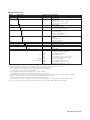
10
Dimensions and Mounting
151
141
22.5
144
80
Unit: mm
144
137
80
4-M6 depth 5
For sensor 2 cable
26.5 26.5 24.7
For sensor 1 cable
44.9
For power supply
20.2
For grounding cable
Poly carbonate Housing
Unit: mm
160.1
150.1
165
80
4-M6 depth 5
165
32.6
137
80
For sensor 2 cable
26.5 26.5 23.7
For sensor 1 cable
45
20.2
138
Stainless Steel Housing
Nut
Approx.
55(2.2") 49
(1.93")
Adapter
Conduit adapter
GS 12A01A02-01E-E
Unit: mm(inch)
Packing
G1/2 screw (/CB4), 1/2 NPT screw (/CD4)
M20 screw (/CF4)
For power supply
For grounding cable
11
min.185 (7.25")
+1
M5
138 0
(5.43")
M6
138
(5.43")
Unit: mm(inch)
Thickness: 1 to 12
min.195(7.75")
138(5.43")
M6
+1
138 0
(5.43")
Option /PM: panel mounting diagram
Unit: mm(inch)
wall mounting
pipe mounting
(vertical)
14
(0.55")
80
(3.15")
pipe mounting
(horizontal)
2x Ф6.5
(0.26")
200
(7.87")
4x Ф10
(0.4")
35
(1.38")
15
(0.6")
70
(2.75")
164
(6.46")
2" ND. pipe
Option /U: wall and pipe mounting diagram
10
Unit: mm
(50)
199
57
220
72
184
(70)
(100)
Housing with stainless steel hood (Option /H6 /H7 /H8) (Poly carbonate housing)
10
(50)
165
199
Unit: mm
72
220
57
184
165
(70)
(100)
Housing with stainless steel hood (Option /H6 /H7 /H8) (Stainless steel housing)
Note: W
hen option code “/UM” is specified, universal pipe/wall/pannel mounting kit are supplied
---same as option code “/U” and “/PM” both specified.
GS 12A01A02-01E-E
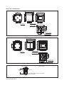
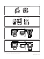
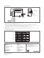
Wiring Diagrams
BA10*S
Terminal box
Case of Distributor
SDBT
FLXA21 2-Wire Analyzer
–
+ B
A
n n n n n n n n n *3
BA10*S
Terminal box
Case of Distributor Output 2 (1-5V DC)
*7
SDBT
Output 1 (1-5V DC)
FLXA21
*4
n n
n n n2-Wire
n n nAnalyzer
n
–
+ B
A
Sensor
n n n n n n n n n *3
*1
+
–*4
n n n n n n n n n
*6
Sensor
Sensor
*2
(Stainless steel
housing)
BA10*S
Terminal box
L N
–
+ H
F
Power
supply
Output
2 (1-5V DC)
*7
20 to 130V DC
or Output 1 (1-5V DC)
80 to 138V AC, 47 to 63Hz
+
1 –
2
*6
*1
*2 +
*2
(Stainless steel – (Plastic housing)
housing)
BA10*S
Terminal box
–
+ H
F
L N
*6
+
1 –
2
*6
Power supply
20 to 130V DC
or
80 to 138V AC, 47 to 63Hz
*2
(Plastic housing)
Sensor
*1: Use a 2-conductor shielded cable with an outside diameter of 6 to 12 mm.
*2: Ground FLXA21 ( Class D ground: 100 ohm or less)
The way of connecting the grounding cable varies depending on the poly carbonate housing and stainless steel housing.
In the case of the poly carbonate housing, connect the grounding cable to the terminal of the power module inside, and in the case of
the stainless steel housing, connect the grounding cable to the terminal of the housing.
Use a cable with an outside diameter of 3.4 to 7 mm for the grounding line of the poly carbonate housing.
*3: Refer to module
*4: Two modules can be connected to the same object. When measuring inductive conductivity, only one module can be connected.
*5: The terminal box may need to be connected depending on the object under test or the sensor selected.
*6: This line is connected to a distributor.
*7: Two outputs of SDBT are same.
11
12
14
18
13
17
19
15
16
PH Module
SC Module
PH Module
ISC Module
SC Module
DO Module
PH
11
11
12
12
13
14
14
18
15
13
16 NC
17 19
11
11
12
12
13
13
17
14
14
15
16
16
15
NC
11
11
12
12
16
13
15
17
13
14
14
16
17
15
18
11
12
16
15
13
14
17
18
15
16
ISC
SC
NC
DO
ISC
ISC Module
DO Module
YOKOGAWA ELECTRIC CORPORATION
World Headquarters
9-32, Nakacho 2-chome, Musashino-shi
Tokyo 180-8750
Japan
www.yokogawa.com
YOKOGAWA ELECTRIC ASIA Pte. LTD.
5 Bedok South Road
Singapore 469270
Singapore
www.yokogawa.com/sg
YOKOGAWA CORPORATION OF AMERICA
12530 West Airport Blvd
Sugar Land, Texas 77478
USA
www.yokogawa.com/us
YOKOGAWA CHINA CO. LTD.
3F Tower D Cartelo Crocodile Building
No.568 West Tianshan Road Changing District
Shanghai, China
www.yokogawa.com/cn
Euroweg 2
3825 HD Amersfoort
The Netherlands
www.yokogawa.com/eu
YOKOGAWA MIDDLE EAST B.S.C.(c)
P.O. Box 10070, Manama
Building 577, Road 2516, Busaiteen 225
Muharraq, Bahrain
www.yokogawa.com/bh
GS 12X0X0-E-E
Subject
to change without notice
GS 12A01A02-01E-E
Copyright ©
Subject to change without notice
Copyright©
SC
PH
NC
DO
Yokogawa has an extensive sales and
distribution network.
Please refer to the European website
(www.yokogawa.com/eu) to contact your
nearest representative.
Printed in The Netherlands, 00-000 (A) I
Printed in The Netherlands, 2-0111 (A) I


![Model DO402G Dissolved Oxygen Converter [Style: S3]](http://vs1.manualzilla.com/store/data/005725233_1-bd7e4c5bf258da59a958f30153ff00ea-150x150.png)