1
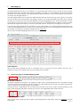
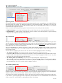
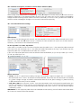
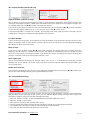
System Manager User’s Manual Firmware version 1.80 As at 22th February 2014 Prostage S.L. • Apdo 57 • ES-07560 Cala Millor [email protected] • www.prostage.eu Table of Contents 1 Introduction 4 1.1 1.2 System Manager Features The Prostage System 4 4 2 MIDI Crash Course & Definition for Guitarists 5 2.1 2.2 2.3 2.4 2.5 2.6 2.7 2.8 2.9 MIDI StageWire MIDI channel Stompbox Mode (Instant Access) = > Direct On/Off Switches Program Change | PC => Recall of Pre-Programmed Settings Control Change | CC = > Real-time control with an Expression Pedal (e.g. Volume) MIDI Mapping Relay Expression Pedal 5 5 5 5 6 6 6 6 6 3 Software-Installation 7 3.1 3.2 3.3 Installing the System Manager Software (Mac & PC) Installing the USB Driver on Mac OSX Installing the USB driver on Windows 7 7 7 4 First Steps 8 4.1 4.2 4.3 Communication with the XDS | XLS | XTMpro The File Menu The Edit Menu 8 8 8 5 Loops | Switching Outputs 9 5.1 5.2 5.3 5.4 Switching the Loops | Switching Outputs using Program Changes Switching the Relays with Instant Access Switches (Stompbox Mode | Direct Switching w/o Presets) Linking Relais | Stereo Operation Switch Impulses 9 10 10 10 6 Tap Relay 11 6.1 6.2 Use as Tap Relay Use as Programmable Switch 11 11 7 MIDI Mapping 12 7.1 7.2 7.3 7.4 7.5 7.5.1 7.6 General Settings of the MIDI Mapping Table Defining Mappings Mapping Mode “Program Number” Mapping Mode “Control Change” Mapping Mode “Convert incoming CC” Scale and invert the values of Control Change commands Mapping Mode “Send Tap Tempo” 12 13 14 15 16 17 18 8 MIDI Switches 19 8.1 8.2 8.3 Receiving CC Messages | Switching the Relays with a standard MIDI Foot Controller Sending CC On / Off Messages | Instant Access The MIDI Switches list 20 20 21 Page 2 9 Basic Settings 22 9.1 9.2 9.3 9.4 General Settings MIDI Thru (Data NOT processed by the MIDI mapping) Tap Function MIDI commands Loops | Switching Outputs 22 22 23 24 10 Foot Controller 25 10.1 10.2 10.3 10.4 10.5 10.6 10.7 10.8 10.9 The Foot Controller List Rename the Foot Controller Operating Modes Tap Switch Sidekick (X05 & X10) Number of Programs | Number of Instant Access Switches (X07) Foot Controller Basic Settings Display Settings (X05 & X10 only) Using Default Settings 25 25 26 26 26 27 27 29 29 11 Remote WahWah 30 11.1 11.2 How to sync the Remote WahWah with the System Manager Store and Recall Presets 30 30 12 Firmware Upgrade 31 12.1 How to Upgrade the Firmware of the XDS | XLS | XTMpro 12.2 How to Upgrade the Firmware of a Foot Controller 31 31 13 Appendix A | Block Diagrams 32 13.1 13.2 13.3 13.4 13.5 13.6 Switching the Loops | Switching Outputs with Control Change commands from a standard MIDI foot controller Sending CC messages when a switch on the XDS | XLS | XTMpro is pressed manually Sending CC messages, when the Loops | Switching Outputs are switched by a preset change StageWire Flowchart MIDI In Flowchart Manual Operation Flowchart 32 33 34 35 36 37 14 Apendix B | MIDI Implementation Chart 38 14.1 Control Change List 39 NOTE => This manual uses digital bookmarks. You can show them by clicking on the "flag" icon in the top left of Acrobat Reader. A click on a topic flips directly to that chapter. Page 3 1Introduction Dear Customer Thank you for buying the world's most advanced system for switching and controlling guitar rigs. The Prostage looper | switcher and the foot controllers are a coherent system you can manage using the System Manager software. 1.1 System Manager Features •Available for Mac OSX and Windows. •Programming of the Prostage looper | switcher (XDS | XLS | XTMpro). •Programming of all Prostage foot controllers (X10 | X07 | X05 | X01). •Programming of the Prostage Remote WahWah & Remote Volume (VCA). •Connects to the XDS | XLS | XTMpro via USB. •Firmware upgrades for the looper | switcher and the foot controllers. •Offline Tool: The software also works without a connected device. •The settings can be saved to the computers hard drive and can be loaded from there. •It's freeware. 1.2 The Prostage System A Prostage system usually consists of a looper | switcher and one or more foot controllers with which the looper | switcher is controlled remotely. This system differs from conventional pedal boards as only the switch (i.e., the foot controller) is placed at the front of the stage. The effects devices are firmly installed in a rack and located next to the amplifier. This brings great benefits: •Higher reliability: There are no plugs you can tread on. The connectors on the foot controllers are positioned in a way that prevents the plugs from damage by treading. •Better audio quality due to shorter cable runs. •Faster construction: You have to run only one cable between the rack | guitar amplifier and the foot controller. Done! The devices are plug & play. That means you can plug them in and use them directly, without having to configure anything. If you press a switch on the foot controller, the loops and switching outputs of the XLS | XDS | XTMpro are switched. The Prostage devices offer many possibilities more. It can, for example, send a wide range of MIDI commands to effect equipment and guitar amps. To configure these advanced features, you need the System Manager software. The brain of each Prostage system is located in the XDS | XLS | XTMpro. These three devices have the identical brain. This means they use the exact same software, offer identical MIDI functions and can be programmed equally by using the System Manager software. The devices differ only by the housing and the connection options. Within the foot controller, only a few basic settings such as the operation mode or the assignment of special switch functions are stored. The fact that the cerebrum is inside the XDS | XLS | XTMpro is helpful especially if you work with multiple foot controllers. You do the programming (e.g. the MIDI mapping) only once and do not have to copy settings between the foot controllers. The philosophy of Prostage is "control without limits". There are lots of things you can configure using the System Manager. Once the system is configured, you can control your equipment very easily and comfortably with a single tip of your toe. If you have any questions, please do not hesitate to contact us: [email protected]. We are also looking forward to your suggestions concerning new features. We are still working to improve the functionality of the system. The Prostage team wish you lots of fun with your Prostage system and much success in your musical career. Luke Truninger Founder & Developer Page 4 2 MIDI Crash Course & Definition for Guitarists 2.1 MIDI MIDI stands for “Music Instrument Digital Interface”. MIDI is the global standard for transmitting notes and control commands to and from all kinds of electronic instruments and sound-processing equipment. MIDI is a serial interface which transmits only control information - not audio data - between music instruments and devices. For example, if you connect a keyboard to a computer via MIDI, the computer - or the sequencer software - can play on the keyboard. The sequencer tells the keyboard which key to play with what velocity. In other words, the computer is practically pressing the keys. The sound is not transmitted by MIDI, but is formed by the keyboard. It is of course also possible, to connect several devices together. Besides notes, MIDI can also transmit all kinds of control commands. For example, the sequencer tells the keyboard what kind of sound (e.g. piano, violin, etc.) the subsequent notes should be played with. To this end, the sequencer selects a certain program number in which the required sound is stored. Using these Program Change commands, numerous effects and settings can be recalled in effect devices. Program Change commands switchover the settings of the connected devices. The various sound settings of modern guitar amplifiers are usually switched using MIDI. Control Change commands can control adjustable values - so called parameters (eg volume) - in real time. That is, the settings of the effect can be adjusted. Or they switch on and off certain functions (such as bypass ). The on-/ off functions are also called "Instant Access" or "Stompbox Mode". Detailed information about MIDI can be found on www.midi.org and many other sites on the internet. 2.2 StageWire StageWire is a further development of MIDI. The connection has ben developed by Prostage specifically for use on stage. With only one microphone cable from one device to the next, multiple devices can communicate with each other (bidirectional). StageWire is four times faster than MIDI. Furthermore, the microphone cable supplies the foot controllers with power. 2.3 MIDI channel Using MIDI, you can control up to 16 devices independently from each other. To do so, different commands are sent on different MIDI channels. Each device responds to commands from its MIDI channel. It's as if you could control 16 different TV-sets with one remote control. Example: •The guitar amplifier is set up to receive on MIDI channel 1. •An effect unit is programmed to MIDI channel 2 •The Prostage system is now programmed in a way that pressing a single switch on the foot controller simultaneously sends a command for the amplifier on channel 1 and another command for the effect device on channel 2. This list of commands is created in a so-called MIDI mapping (see chapter 2.7). => If the two devices shall follow the same commands, they can also be set to receive on the same MIDI channel, of course The MIDI channel is set once within the sending unit and once at the receiver. Both settings must match, so that the receiver (e.g. the effects unit) responds to the commands from the transmitter (e.g. the foot controller). For the MIDI receive channel, there is the option "Omni". This means that the unit receives all MIDI commands - regardless of the MIDI channel. This means, the unit responds to all commands. In other words, if you use this setting, it does not matter on which channel the command was sent. The Prostage system is factory set to "Omni". That's always the right setting, as long as you do not want to control individual devices with different commands. 2.4 Stompbox Mode (Instant Access) = > Direct On/Off Switches StageWire allows you to use up to eight switches on the foot controler as direct on/off switches - for example, to switch the loops of the XDS. These on/off switches work like an analog foot switch connected directly to the amplifier. Thus, the button on the foot controller switches directly a switch on the looper | switcher. An Instant Access (on/off switch) command consists of: •MIDI channel (1-16) •Switch number (1-8 ) •Switching state (on/off) Page 5 Using standard MIDI pedals, these functions are made with Control Change commands (see chapter 2.6 ) 2.5 Program Change | PC => Recall of Pre-Programmed Settings With Program Change messages, previously saved settings (presets) are recalled. Using MIDI, you can manage 128 different presets by default. On MIDI-equipped guitar amps, the various sounds are switched like this. Example: •The guitar amplifier is programmed as follows: Ampchanel Program in the Preset 1 => Clean channel 1 2 3 effects unit Sounds: Preset 2 => Crunch channel Clean Sound with Chorus effect Preset 1 o o o Chorus Preset 3 => Lead channel •In the effect device, the Crunch Sound without effect Preset 2 o o o Bypass following presets are stored: Lead Sound with Delay Preset 3 o o o Delay Preset 1 => Chorus Preset 2 => Bypass Preset 3 = > Delay •At the foot controller you can now access the presets by pressing the buttons 1-3 and you will get the sounds listed in the table. Using presets, not only individual functions are turned on and off, but all devices can be switched with a single foot step. When using the Prostage XDS, you can switch all eight effects pedals at once. Your live-performance will no longer be interrupted by tap-dancing on several devices. We use the short form “PC” in the System Manager software for MIDI “Program Change” message. A Program Change consists of: •MIDI channel (1-16) •Program number ( 0-127 ; many devices show them as 1-128 ) There are also devices that can handle more than 128 presets. They use so-called "Bank Select" commands to switch to the next level with additional 128 presets. 2.6 Control Change | CC = > Real-time control with an Expression Pedal (e.g. Volume) The abbreviation CC stands for MIDI "Control Change." Control Change are commands with which parameters (eg volume) are controlled in real time. To this end, an expression pedal sends - as long as it is moved - so called Continuous Controller and tells the effects device its position. Control Changes can also switch functions at the receiver device on and off. A CC- command consists of: •MIDI channel (1-16) •Controller number (0-120) => This defines which parameter is controlled. The most commonly used controller number is 7 which controls the volume. •Controller value (0-127) => 0 = "low", 127 = "high". Using switching commands, the value 0 means "off", 127means "on". Often, equipment interpret the value 1 as a switch-on command. 2.7 MIDI Mapping A MIDI mapping allows you to send several MIDI messages by pressing a single switch. Different program numbers and commands are sent on different MIDI channels to various devices. The mapping will be programmed in a table. The Prostage system offers eight columns. This means that eight different commands can be sent simultaneously. 2.8 Relay The Prostage looper | switcher are using relays for switching the audio loops and switching outputs. Relays are switches which can be controlled remotely. 2.9 Expression Pedal An expression pedal is a kind of volume pedal that is connected to a MIDI foot controller (or which is part of the foot controller). However, the expression pedal does not control a guitar signal, but generates MIDI Continuous Controller, with which for example the volume, the effects mix or the delay time can be adjusted in an effects device. The expression pedal controls a parameter of the effect unit in real time. Page 6 3Software-Installation Please download the newest version of the System Manager software and the latest USB driver from our website: www.prostage.eu => Support => Downloads 3.1 Installing the System Manager Software (Mac & PC) •Unzip the downloaded file. •Move the folder “Prostage System Manager xxx” into your local application folder. (DO NOT move any files inside the folder to other locations). 3.2 Installing the USB Driver on Mac OSX •Double click the downloaded file (.dmg) and follow the on-screen instructions. 3.3 Installing the USB driver on Windows •Unzip the downloaded file. •When you connect the XDS | XLS | XTMpro for the first time, the assistant will ask you for a driver => Here, you have to select the path where you stored the unzipped folder with the USB Driver before. If the wizard does not open automatically, you need to install the driver via the “Device Manager”. Unfortunately, this is different from Windows version to Windows version: Windows 2000: Start / Settings / Control Panel => System => Hardware / Device Manager Windows 7: Windows icon left corner below / Control Pannel => System & Security => System => Device Manager The XTMpro should now appear under “Com & LPT” or “USB” or “Other Devices”. Double click “XTMpro”. This will open a new window. Click the button “Update Driver”. Select “Manual Installation”. This opens the file dialog window. Select the file “XTMpro USB driver” (the previously unzipped driver, NOT the zip file!). Now the driver should be installed. NOTE => The USB driver may install and appear as “FTDI Driver”. Page 7 4 First Steps IMPORTANT NOTE => The screen shots in this manual do not show the factory settings of the devices, but a ready programmed setup. This should help you to better understand the possibilities and the programming of the system. 4.1 Communication with the XDS | XLS | XTMpro Connect the XDS | XLS | XTMpro using a USB cable to the computer. The System Manager is an offline tool. In order to show the current settings of the XDS | XLS | XTMpro, they must be read out first. This happens automatically when you launch the software given that the XDS | XLS | XTMpro is properly connected with the computer. Otherwise, you have to read out the XDS | XLS | XTMpro manually: [File] => [Read XDS | XLS | XTMpro]. Changes made in the System Manager are not automatically applied by the XDS | XLS | XTMpro but have to be confirmed with [Update XDS | XLS | XTMpro]. Thus, you can create settings quite easily at home, and submit them to the XDS | XLS | XTMpro in the rehearsal room later. [Update XDS | XLS | XTMpro] will send all settings of [Loops | Switching Outputs], [Tap Relay], [MIDI Mapping], [MIDI Switches] and [Basic Settings] to the XDS | XLS | XTMpro. The foot controller and Remote WahWah settings are not stored in the XDS | XLS | XTMpro but in the foot controller or the Remote WahWah respectively. If you make any changes in one of the two tabs, you have to confirm them with the button [Update Foot Controller] or [Update WahWah] / [Store Preset]. TIP => If you are working with two or more XDS | XLS | XTMpros, you have to read out the settings each time you plug the USB cable into a different device. Otherwise, you will mix the settings of the different devices. NOTE => The preset names, as well as the description of the eight MIDI Mapping columns and the relays are only saved to your hard disk. They are not stored in the XDS | XLS | XTMpro. Thus, we recommend to save your settings to the hard disk as well (see chapter 4.2, "The File Menu"). 4.2 The File Menu [Open Configuration] Loads the settings for the XDS | XLS | XTMpro stored on the local hard drive into the System Manager (file extension .pcf) [Save Configuration] Saves the settings from the System Manager to your local hard disk; the current file is overwritten. Stored are all settings from [Loops | Switching Outputs], [Tap Relay], [MIDI Mapping], [MIDI Switches] and [Basic Settings], as well as the foot controller default settings. [Save Configuration As] Same as [Save Configuration], but a new file will be created. [Read XDS | XLS | XTMpro] Loads the settings from the connected XDS | XLS | XTMpro into the System Manager. [Update XDS | XLS | XTMpro] Sends the current settings from the System Manager to the XDS | XLS | XTMpro. [Reset >] Restores the factory defaults for selectable sections inside the System Manager. [Open WahWah Presets] Loads the presets of the Remote WahWah | Remote Volume stored on the local hard drive into the System Manager (file extension .pwf). [Save WahWah Presets] Saves the presets for the Remote WahWah | Remote Volume to your local hard disk; the current file is overwritten. [Save WahWah Presets As] Same as [Save WahWah Presets], but a new file will be created. [Page Setup ...] Allows you to adjust the paper size for printing the [MIDI Mapping] table. [Print Patch List ...] Prints the entire [MIDI Mapping] table (patch list). [Quit] Closes the software. 4.3 The Edit Menu [Toggle Preset] Opens a dialog box where you can interchange the current selected preset with another preset. The settings in [Loops | Switching Outputs], [Tap Relay] and [MIDI Mapping] of the two presets will be exchanged. Page 8 5 Loops | Switching Outputs NOTE => If you're using a XTMpro without relay option, you cannot do anything in this tab. „Relay B1 - B4“ are only available if you are using an XDS or XLS system with both groups equipped. 5.1 Switching the Loops | Switching Outputs using Program Changes The [Loops | Switching Outputs] tab allows you to easily make presets for the eight loops | switching outputs by enabling/disabling the check boxes. This is the same what you can switch directly on the device. The relays may work independently from each other or they can be combined in “radio button” groups (see chapter 9.4). Controlled Unit | Preset Name You can label the relays in order to know which function each one controls. You can also name each of the 128 presets. The preset names also apply to the [Tap Relay] and [MIDI Mapping] tab. The names will not be stored to the XDS | XLS | XTMpro, but they will be saved with the file saved to the hard disk [File] => [Save Configuration]. Receive on MIDI CH The MIDI receive channel must be set to the same number on which the foot controller sends. The relays only respond to Program Change or Instant Access (on/off switch) commands if the MIDI channel matches. Only in the setting "Omni", all 16 MIDI channels are accepted. In this setting, it does not matter on which channel the foot controller sends. This MIDI channel will also be used to send an “on/off” command to the foot controller when a relay at the XDS | XLS | XTMpro is switched. Thus, the LEDs on the foot controller always show the current switch positions. If the MIDI channel is set to “Omni”, it will send on MIDI channel 1. Page Since the screen is too small to display all 128 presets simultaneously, it shows only ten presets at a time. Use the [Page] pull-down menu to flip through all preset numbers. Show There are MIDI devices that work with preset numbers 0-127. Others work with 1-128. Therefore, there may be an offset of 1 between different devices. The setting [Show] helps you to avoid this. If the lowest number of your foot controller is 0, choose [Show] “0-127”. If the lowest number of your foot controller is 1, choose “1-128”. This way, you avoid an offset of 1. If your foot controller works with songs instead of presets, you can also display the song and sound numbers here. Page 9 5.2 Switching the Relays with Instant Access Switches (Stompbox Mode | Direct Switching w/o Presets) You can control the Loops | Switching Relays in a “Stompbox Mode”. This means, a switch on the foot controller directly turns a relay on and off. Foot Controller Switch If you have connected a Prostage foot controller to the StageWire Input, you can assign each relay directly to a switch of your foot controller. The foot controller has to be setup to send this button on/off messages. If you do not want to assign a relay to any foot controller switch, choose "None". The relay will still switch by preset changes and when you switch it manually at the XDS | XLS | XTMpro. Below the pull-down menu, the software displays how the switch is labeled on the foot controller. For example, if you use the X01, the names of the switches are “A,B,C,D” instead of “1,2,3,4”. •Example: You like to use the upper row of the X07 (switches 4-7) to switch the four relays on the XTMpro, while using switches 1-3 of the foot controller to control something else. To do so, you have to set the following: Relay A-1 => Switch 4 Relay A-2 => Switch 5 Relay A-3 => Switch 6 Relay A-4 => Switch 7 If you like to switch the relays using a standard MIDI foot switch connected to the MIDI In of the XDS | XLS | XTMpro, you have to setup [MIDI Switches]. Please refer to chapter 8 for more information. 5.3 Linking Relais | Stereo Operation You can link two or more relays by assigning them to the same foot controller switch, for example, to make a stereo pair. If several radio buttons are assigned to the same foot controller switch, you can step through the radio buttons by tapping the switch on the foot controller. If two radio buttons are linked, you can toggle between the two radio buttons using the switch on the foot controller. Radio buttons are explained in chapter 9.4. 5.4 Switch Impulses Send Pulse Some units require a brief impulse (momentary) to switch on and another impulse to switch off instead of a constant on/off signal. To control such units, enable the [ Send Pulse] check-box. After you have switched on the system, make sure that the switches of the controlled unit are in the correct on/off position. If this is not the case, change them manually directly at the controlled unit once. Otherwise, the on/off state of the device switch(es) will be reversed. Page 10 6 Tap Relay In the [Tap Relay] tab you decide whether you want to use the relay output from the XDS | XLS | XTMpro as tap relay or as a programmable switch. 6.1 Use as Tap Relay If the relay is used as tap relay, the tap command of the foot controller (see chapter 10.4) is sent on this connection. Thus, the tap command is forwarded to the connected effects device. You can choose whether the tap relay should work as a momentary switch or as a latching switch: Momentary => When you press the tap switch on your foot controller, the tap relays will switch on. When you release the switch, the relays will switch off - like a doorbell switch. Latching => When you press the tap switch on your foot controller for the first time, the relay will switch on. When you press it a second time, the relay will switch off, and so on - like a light switch. The correct setting for it depends on the connected device. Usually, [ momentary] is the correct setting. Just try which setting is the right one! Furthermore, the tap relay can be switched by a MIDI Control Change command. Please see chapter 9.3 for more information about this. 6.2 Use as Programmable Switch If the relay is used as a programmable switch, this output works the same way as a "Switching Output". The operation is described in chapter 5. However, the tap relay can only be programmed with the System Manager software, there is no button at the device for manual operation of the relay. Receive on MIDI CH The tap relay has its own MIDI receive channel. It is independent from the MIDI channel of [Loops | Switching Outputs]. Page | Show | Preset Name These are the same settings that you also do in [Loops | Switching Outputs] or [MIDI Mapping]. Please refer to chapter 5 for more information. Page 11 7 MIDI Mapping The MIDI mapping of the XDS | XLS | XTMpro is a very powerful tool, with which you can do all sorts of things. Most likely you'll never take advantage of all the possibilities. Therefore, it is not mandatory that you understand all the details of the MIDI mapping. The mapping mode [Program Number] is certainly interesting for every guitarist. So read at least through chapter 7.3. The MIDI mapping allows you to send up to eight different MIDI commands when you recall a preset. If you select a preset number on the foot controller, the program number is not simply forwarded to the MIDI OUT A and B of the XDS | XLS | XTMpro, but the commands defined in the [MIDI Mapping] are sent. All the commands in the row of the preset are sent. Tthis means, that for each preset you can send eight different program numbers or other commands to eight different devices, each on its own MIDI channel. The table can manage up to 128 presets. If the complete [MIDI Mapping] tab is disabled or if the MIDI channel of the received MIDI command does not match the setting of [Receive PC on MIDI CH], the MIDI command will be sent unchanged to the MIDI Outs based on the MIDI thru settings in the [Basic Settings] tab (see chapter 9.2). You can print the [MIDI Mapping] table: [File] => [Print Patch List] Controlled Unit You can label each controlled unit with a meaningful name. The names will not be stored in the XDS | XLS | XTMpro, but they will be stored if you save the settings to the hard disk. 7.1 General Settings of the MIDI Mapping Table Receive PC on MIDI CH The [MIDI Mapping] tab processes only program changes with a matching MIDI channel. All Program Change messages on other channels will be sent to the MIDI Out A/B according to the settings in the [Basic Settings] tab. "Omni" means that all 16 MIDI channels are accepted. The MIDI channel is independent from the MIDI receive channel of the relays. [Loops | Switching Outputs], [Tap Relay], [MIDI Mapping] and [MIDI Switches] all have their own independent MIDI receive channel. Page | Show | Preset Name These are the same settings you do in [Loops | Switching Outputs] or [Tap Relay]. Please see chapter 5 for more information. Page 12 7.2 Defining Mappings You can choose between four different mapping functions for each of the eight columns (see chapter 7.3 to 7.6), or you can disable the column. Each mapping has its own transmit settings: Send on MIDI CH Chooses the MIDI transmit channel for the commands of this mapping column. If you use several columns for "Program Change" mappings, they have to use different MIDI channels. You cannot send several program changes on the same MIDI channel simultaneously. Different MIDI devices have to use different MIDI channels in order to control them independently. To Out A | Out B Selects on which MIDI Out(s) the commands will be sent. In the mapping mode "Control Change", MIDI messages can not only be sent to MIDI Out A and B, but also to the foot controller. "XLR" stands for the StageWire bus. 0-127 / 1-128 If the controlled unit’s preset numbering starts with 0, choose “0-127”. If the unit’s lowest preset number is 1, choose “1-128”. Doing so, you will prevent an offset of 1. Page 13 7.3 Mapping Mode “Program Number” In this mode, Program Change mappings are defined. This means that you can allocate an individual preset number of the controlled device to each preset number on the foot controller. If you setup Program Change mappings for multiple devices, you can recall another preset number in each connected device with a single button on the foot controller. 5 •Taken the example above, the following happens when you select preset no. 5 on your foot controller: First, the XDS | XLS | XTMpro checks if the [MIDI Mapping] is enabled and if the MIDI channel of the foot controller matches the [Receive PC on MIDI CH] setting. If one of these conditions is not given, the Program Change is forwarded to MIDI Out A/B according to the [Basic Settings]. If both conditions are true, the following program changes will be sent: - Preset no. 3 to Amp (e.g. Lead channel) - Preset no. 5 to Axe FX (e.g. Delay) - Preset no. 0 to Remote WahWah (Bypass) 8 •If you recall preset no. 8 in this example, the following commands will be sent: - Preset no. 1 to Amp (e.g. Clean channel) - Preset no. 99 to Axe FX (e.g. Mute) - Preset no. 3 to the Remote WahWah (Contour Wah) NOTE => If the box is empty, no preset number will be sent at all. Page 14 7.4 Mapping Mode “Control Change” You can also send Control Change messages instead of program changes. For example, you have connected a TC G-Major to the XDS | XLS | XTMpro, but you like to work with the same preset all the time and only turn on/off the effects (e.g. Delay, Reverb, Flanger, Compressor), as you would use stompboxes. You can do so by sending CC commands. Besides the controller number, you also have to send a controller value. Value 0 means “off”, value 127 means “on”. Of course the TC G-Major also has to be programmed properly in order to work this way. 1 •Taken the sample above, the following happens when you recall preset no. 1. If the MIDI mapping is enabled, and the MIDI channel matches, the following MIDI messages are sent: =>CC 82 with value 127 to the G-Major (Chorus = On). =>No command to the Remote WahWah, since no number is defined. (If you recall any other preset, the chorus is turned off => Control Change 82 with value 0). 8 •If you recall preset 8, the following MIDI messages are sent: =>The Chorus is turned off (CC 82 with value 0) =>The frequency of the Remote WahWah will be set to approximately 1,1kHz (CC 93 = WahWah frequency). This will result in a lower WahWah effect than the standard WahWah (For any other preset no CC command is sent to the WahWah because the CC # field is empty). Page 15 7.5 Mapping Mode “Convert incoming CC” With this mapping, an expression pedal can be used for something else at each program number. Different effect parameters can be controlled depending of the selected preset. Mapping Control Changes (Continuous Controller) is a unique feature of the Prostage XDS | XLS | XTMpro and works a little differently than the other mappings. At preset change, no command is sendt at all. Instead, Continuous Controller commands such as “Volume”, are converted to other CC commands in real-time. The setting of [Receive PC on MIDI CH] has no influence on the Continuous Controller commands. Decisive is the MIDI channel set in the mapping column [On MIDI CH:]. The following example assumes that an expression pedal that sends CC # 7 (Volume) is connected to the foot controller. 8 CC #7 •In preset no. 8 you like to use the expression pedal to control the "Contour Boost" frequency of the Remote WahWah instead of the normal WahWah effect. => Therefore, you set the CC no. to 94 (this is the Contour Boost frequency of the Remote WahWah). 8 CC #7 •In preset no. 6, you like to control the normal WahWah effect of your Remote WahWah. => Thus, you send CC no. 7 (this means that the same command is sent as received). In this example, if you select any other preset than 6 or 8, your expression pedal is inactive because the “CC#” field is empty (incoming Control Change commands will be filtered / muted). NOTE => Incoming Control Change commands that are not subject to convert in any of the eight colums will be sent to MIDI Out A/B according to the [Basic Settings] (see chapter 9.2). In our sample, this means that only CC no. 7 on MIDI channel 1 is processed by the MIDI Mapping. All other CC commands received by the XDS | XLS | XTMpro will be sent via MIDI Out A/B without any modification of the data. Page 16 7.5.1 Scale and invert the values of Control Change commands In the mappingmode "Convert incoming CC", Control Change values can also be inverted and scaled. This means that you can invert the direction of your expression pedal and scale it, for example, to affect only 50% of the effect at full movement of the expression pedal. If a CC number is defined, a click on the [ Scale] check-box to the right of the number opens the dialog box for entering this additional settings. •In this example, the resolution of the Control Change value is scaled to 50%. This means that, instead of 128 possible values, only 64 values will be sent. Because lowest value is set to "31", the values received from the expression pedal (0-127) will be forwarded to the Remote WahWah as 31 to 95. In this example, the expression pedal controls the middle frequencies of the Contour Boost, while not reaching its very low and very high frequencies. •In this example, the direction of the expression pedal is inverted. That means, if you want to make the guitar louder, you have to move the expression pedald down. To make it quieter, you have to move it up. In bank 5-8, you can further set an individual MIDI channel for each preset on which the modified CC is sent. This means you can even control different devices with the same expression pedal. If this field remains empty, the CC will be sent on the same MIDI channel on which it has been received. You can also use this feature if you want to use an Instant Access (on/off) switch of your foot controller for different things, depending on the selected preset number. Thereto, the output assignment for this switch in the [MIDI Switches] tab has to be set to “use MIDI Mapping”. •For example, you use switch 5 to turn on/off the distortion in the Fractal Audio AxeFX. But on one preset, you want to switch a different function instead. Therefore, convert the incoming CC in this specific preset to send the required command to the AxeFx. Of course, you have to program the AxeFx accordingly. Page 17 7.6 Mapping Mode “Send Tap Tempo” In mapping mode “Send Tap Tempo”, the XDS | XLS | XTMpro sends impulses on each preset change. These commands can be used to adjust (tap) the tempo of effects devices (e.g. for delay). The pulses can either be sent as MIDI CC commands to MIDI Out A/B, or using the tap relay. CC #: This is the MIDI CC number that is used to send the tap pulses. The turn-on pulse is sent with value 127, the turn-off pulse with value 0. This setting has no effect to the tap relay output. Pre Delay: Usually at a preset change, the effects device must load the new preset first before it can receive tap commands. Therefore, the tap command can be delayed. Settings from 0 milliseconds to 996 milliseconds are possible. This setting affects both the output via MIDI as well as the tap relay. m. / la:. This defines whether the tap is sent as a “momentary” or as a “latching” command. The difference between “momentary” and “latching” is explained in chapter 9.3. Usually, [m.] is the right setting. When set to [m.] the XDS | XLS | XTMpro sends three pulses. When set to [la.] it sends two on and two off commands. BPM: The time between pulses is set as song tempo BPM (beats per minute). It can range between 20 BPM (= 3 sec) and 274 BPM (= 219ms). 5 Note => The CC number, the pre-delay and setting [m.]/ [la.] are global. They are identical for all presets. Page 18 8 MIDI Switches StageWire offers eight Instant Access switches that allow you to switch the loops and switching outputs directly. In order to make these switching functions also available via MIDI, you can allocate a Control Change number to each of these switches in the [MIDI Switches] tab. These CC commands are used if you want to switch the relays of the XDS | XLS | XTMpro with CC commands received at the MIDI In. Prostage foot controller Standard MIDI foot controller 5 Instant Access 5 Control Change StageWire Foot Controller Switch MIDI In XDS XLS XTMpro The same commands can also be sent to the MIDI Outs when you switch the loops manually or by a Prostage foot controller (via StageWire). In addition, you can send notes numbers or special functions (e.g. System Realtime Start/ Stop). Receive on MIDI CH This MIDI channel setting affects two things: •[Receive on MIDI CH] must match the MIDI channel of the foot controller connected to MIDI In if you like to control the switching functions of the XDS | XLS | XTMpro with CC commands. •[Receive on MIDI CH] must match the MIDI channel of the Prostage foot controller to send the commands defined in the list to the MIDI Outs. Page 19 8.1 Receiving CC Messages | Switching the Relays with a standard MIDI Foot Controller CC received on MIDI In Use Control Changes to switch the Loops | Switching Outputs This check-box must be selected in order that the [Loops | Switching Outputs] respond to CC messages at the MIDI In. If a CC assigned to a foot controller switch is received, the relay(s) allocated to this foot controller switch are switched. You can find the detailed logic diagram of this in Appendix 13.1. 8.2 Sending CC On / Off Messages | Instant Access Send CC to MIDI Out When an Instant Access Switch on the Prostage Foot Controller is pushed (StageWire) This box must be checked if you want that the assigned command is sent when pressing an Instant Access switch on the foot controller. When a Loop | Switching Output is switched manually at the XDS | XLS | XTMpro By default, pressing a button on the XDS | XLS | XTMpro only switches the relay. If you want to send a MIDI command as well by pressing this buttons, activate this checkbox. Then, the CC message from the foot controller switch associated with this relay is sent. You can find the detailed logic diagram of this in Appendix 13.2. When a Loop | Switching Output is switched by Recalling a Preset If you want to send the new on/off state of the relays after a preset change, activate this check-box. Each relay, which has changed its on/off state sends the CC command assigned to its foot controller switch. You can find the detailed logic diagram of this in Appendix 13.3. Page 20 8.3 The MIDI Switches list Foot Controller Switch Name The Instant Access switches of the foot controller are listed here. Depending on the model used, the names are different. If the label does not correspond to your foot controller, see chapter 9.1. You can only access those switches which exist on the foot controller. If you are using an X07, only switches 1-7 are accessible. If you are using a X10, switches No. 5-9 are available because you can use the X10 in the operating mode "5 Programs + 5 Instant Access”. If you like to access all eight switches, independently from the connected foot controller, you have to choose the setting „Other“ in [Basic Settings] => [General Settings] => [Foot Controller] (see chapter 9.1). Function | Control Change / Note Number You can assign a function and a CC or note number to each of the eight switches. Using "Special Function", you can assign a special feature to the switch instead, such as a system real-time command. You can see which parameter is controlled by the command on the right of the pull-down menu. You can find a list of all CC messages in the MIDI implementation chart (appendix B | chapter 14.1). On Value | Off Value Here, you define which CC values will be sent for the on and off state of the switch. Usually, on is "127" and off is "0". But you can also send other values. For example, CC95 controls the output gain of the Prostage Remote WahWah. If you are using a MIDI switch with the settings CC = 95 | on value = 24 | off value = 0, you can turn a boost of 6 dB on and off. The controler value 24 corresponds to 6 dB increase in volume in the Remote WahWah. Using "Special Functions", you can invert the switch position instead. MIDI Channel | MIDI Outputs The command is sent on the assigned MIDI channel on MIDI Out A and / or B. CC commands from the [MIDI Switches] can also be processed further using the [MIDI Mapping]. If [ Use MIDI Mapping] is selected, the command is not sent directly to the MIDI output A or B, but according to the settings in [MIDI Mapping] => [Convert incoming CC]. If, in this case, the CC number is not allocated to any [Convert incoming CC] mapping, or if the MIDI channel does not match, no CC is sent at all (see chapter 7.5 for more information). If you have not selected any output, no command will be sent for this switch. Page 21 9 Basic Settings In the [Basic Settings] tab you set the elementary operation of your Prostage system. 9.1 General Settings Foot Controller This setting only concerns the inscription within the System Manager. For example, if you select "X07", the switches will be labeled 1, 2, 3, 4, 5, 6, 7. If you select "X01", the switches will be labeled A, B, C, D. This setting does not affect the functionality of your system. However inside the software, there are only those switches available that also exist on the foot controller. If you want to make all the switches available, you have to set it to “Other”. 9.2 MIDI Thru (Data NOT processed by the MIDI mapping) Here you determine what happens with incoming MIDI data NOT processed by the MIDI mapping. This is the case when the MIDI mapping is "Disabled" (the MIDI mapping is not used), or if the MIDI channel does not match. Send Data from StageWire to Here you choose which Out’s the data from StageWire (by a Prostage foot controller) is routed to. The selected outputs will work as MIDI Thru. Send Data from MIDI In to Here you choose which Out’s the data from MIDI In (e.g. from a standard MIDI foot controller) is routed to. The selected outputs will then work as MIDI Thru. You can also send the data from MIDI In to StageWire. This is, for example, useful if the show is controlled by a sequencer which switches the presets for you. The preset numbers are then displayed on the foot controller. Page 22 MIDI Thru Filter Out A | MIDI Thru Filter Out B You can filter the different types of MIDI data at the MIDI Out A and B. For example, you can set Out A to send Program Change only. This can make sense if you connect a tube amplifier with a MIDI interface which only accepts program changes. IMPORTANT => The MIDI Thru filter only affects data sent directly from the StageWire or MIDI In to the MIDI Out(s). MIDI commands programmed in the [MIDI Mapping] and [MIDI Switches] tab will always be sent to the MIDI Out(s) assigned in the tab, regardless of the MIDI Thru filter settings. This means for example, if you setup a MIDI mapping, which sends a Program Change to Out A, but the check box [MIDI Thru Filter] => [MIDI Out A] => [Send Program Change] is disabled, the program changes from this MIDI Mapping are sent even though. 9.3 Tap Function MIDI commands Tap allows you to adjust tempo-based parameters like delay time by rhythmic tapping onto the tap switch of your foot controller (see chapter 10.4). The tap command is sent to your effect unit either analogously using the tap relay connector of the XDS | XLS | XTMpro (see chapter 6) or digitally by a MIDI command. Send as MIDI The tap command from the StageWire input can be sent as a MIDI-CC command or even be used for System Realtime messages (start/stop). Select a CC number, a MIDI channel, and enable one or both MIDI Outs. If you like to send different CCs to various effects units, choose “multiple” for the MIDI channel. This opens a pop-up window where you can define up to eight individual tap commands. You can send eight different CC commands, each on its own MIDI channel. Tap switch “on” will be sent as value 127. Tap switch “off” will be sent as value 0. Further, you can choose if the tap should be sent as a momentary command, or a latching command: momentary => When you press the “Tap” switch on your foot controller, the chosen CC command with value 127 will be sent. When you release the switch, the CC command with value 0 will be sent. This works like a doorbell. latching => When you press the “Tap” switch on your foot controller for the first time, the CC command with value 127 will be sent. When you press it for the second time, the CC command with value 0 will be sent. The next time, the CC number is sent again with value 127, and so on... When you release the switch, nothing is sent. This works like a light switch. The correct setting for this depends on how the connected unit works. Try it out! Receive as MIDI The tap relay can not only be controlled by StageWire, but also by a MIDI Control Change command on the MIDI In. Therefore, choose a Control Change number and a MIDI channel. If you do not want the tap relay to be switched by any CC command, set [CC No.] to “Disabled”. Page 23 9.4 Loops | Switching Outputs NOTE => If you use an XTMpro without relay option, these settings are not available. “Group B” is only available if you are using an XDS or XLS system with both groups equipped. Group A | Group B Here you define if the relays inside the group shall work independently, or if you like to make radio-button groups (channel switching). Radio buttons means that only one switch is turned on at the same time. This makes sense for channel switching on guitar amps. Let's assume you have an amplifier with three channels: Clean, Crunch & Lead sound. If you switch between the channels of the amplifier - that is, between the three sounds - the channel used before will automatically turn off. So there's only one sound switched on at a time - not the Clean, Crunch and Lead sound together. This relationship is called "radio buttons". Channels (Radio Buttons): Independent Switches: •For example, if you choose ”3 Channels + 1 Independent Switch”, it works as follows: One of the switches 1 to 3 is always "On". Therewith, you control the channels of your amplifier. Switch 4 operates independently from the other switches. Therewith, you control, for example, a boost function or a reverb that can be switched on and off in each channel. If [ Allow Off] is enabled, the active radio button can be switched off. This could be useful when switching channels in an amplifier that can be muted when no channel is active. If you have an eight-channels system, you can also link the radio buttons of both groups by enabling [ Link channels of Group A and Group B]. Soft X-Fade This feature only affects the audio loops. It has no effect on switching relays. You can enable or disable the Soft X-Fade feature for Group A and B independently. Soft X-Fade is a very short fade out / fade in at the Output of the group which suppresses the click that relays can cause. It also makes the preset change sound softer. If you have connected eight stompboxes in series, enable the Soft X-Fade feature only on group B. XDS | XLS | XTMpro Firmware: see chapter 12.1 Page 24 10 Foot Controller The big brain of the system is in the XDS | XLS | XTMpro. For the foot controllers, there are only some basic settings. The settings you make in the [Foot Controller] tab are stored in the foot controller; they are not stored in the XDS | XLS | XTMpro. IMPORTANT => After you have made some changes in the [Foot Controller] settings, you have to click the button [Update Foot Controller] to transfer the new settings to the foot controller. 10.1 The Foot Controller List Foot Controller On the left side, you can see a list with the "Default Settings" for each model. Below, all connected foot controllers are listed. To search for recently connected foot controllers, click [Refresh List]. Select the foot controller you like to setup from this list. 10.2 Rename the Foot Controller Rename Foot Controller You can rename the selected foot controller by clicking the [Rename Foot Controller] button. This makes sense if you have connected several foot controllers. So you can give an individual name to each foot controller to distinguish them better. In order to save the new name in the foot controller, you have to click [Update Foot Controller] after renaming it. Page 25 10.3 Operating Modes Operating Mode The Operating Mode is the general manner how the foot controller works. Depending on the model, different operating modes are available. The detailed functionality of the operating modes is described in the manual of the foot controller. Depending on the foot controller model and the selected operation mode, not all features mentioned below might be accessible. There are two fundamentally different types of commands that can be sent by the foot controller: •Program Change => are used to recall presets of e.g. multi-effect units or a MIDI-capable guitar amplifier. •Instant Access => on/off switches which directly switch a function at the receiving device, e.g. the switching outputs of the XTMpro or the loops of the XDS | XLS. 10.4 Tap Switch The tap function allows you to set the delay time as well as other song-tempo specific parameters of your effect units in real-time. By rhythmically tapping on the the tap switch, the tap relay of the XDS | XLS | XTMpro will switch like a metronome, and MIDI Control Change commands can be sent (see chapter 9.3 for details). This allows a connected effect unit to learn the song tempo. You can enable/disable this function and select a switch which shall be assigned to this function. If one of the switches 0-9 is defined as tap, it is no longer available, neither for sending Program Change commands nor as an Instant Access switch. The X07 indicates tapping by the switch’s LED. X05 and X10 indicate tapping by the dot in the display. •Tap Switch “Last Used” (Only operating modes which send Program Change commands) If you define [ Last Used] as tap switch, the tap function is always assigned to the last pressed number switch. In other words: When you press the number switch for the first time, the program number is sent. Any more presses on the same switch sends the tap command. •Tap Switch “Enter (arrow down)” (Only X05 & X10 in operating mode "Keyboard Style") Tap switch [ Enter (arrow down)] works as follows: If no new program number is preselected (the display does not flash), then the tap command is sent each time you press the [q] switch. If a new preset number is preselected (display flashes), the switch sends the program number. 10.5 Sidekick (X05 & X10) You can define one switch as a sidekick. This works the following way: When you press the sidekick switch, the program number will be sent. When you release the switch, the previous program number (the one selected before using the sidekick switch) will be restored. Sidekick works in all banks (e.g. 4 - 14 - 24 ....). This feature is very handy if you like to play a fill or a short solo. You stay on the switch as long as the fill / solo takes. If you release it, you're playing again with the previously selected sound. You can enable/disable this function and assign a switch to it. Active sidekick is indicated by the dot in the display. Page 26 10.6 Number of Programs | Number of Instant Access Switches (X07) These settings affect only the X07 in the operating modes [ Programs & Instant Access] or [ Instant Access & Programs] respectively. In this operating mode, the X07 is split. This means the first few switches send program changes and the remaining switches send Instant Access commands, or vice versa. Here, you define the number of switches used to send program changes or Instant Access commands respectively. 10.7 Foot Controller Basic Settings MIDI Channel MIDI Channel sets the MIDI-transmit channel. The foot controller will also receive MIDI commands on the same channel. If the check box [ Receive Omni] is selected, the foot controller will receive on all MIDI channels. Otherwise, it will receive on the selected channel only. CC No. Exp.Pedal 1 & CC No. Exp.Pedal 2 Select which CC number shall be sent when using the expression pedals. No. 1 is the expression pedal connected to the tip of the Jack connector. No. 2 is the expression pedal connected to the ring. If you connect only one expression pedal with a standard mono-Jack cable, No. 1 prevails. If you use an expression pedal with a switch to control the Remote WahWah, set [CC No. Exp. Pedal 1] to “Hi Res”, [CC No. Exp. Pedal 2] to “74”. Special Functions: •"Hi Res" => This is a special format used by Prostage. The resolution is eight times higher than a CC command. We recommend to use "Hi Res" to control the Remote WahWah. Please note that this command is not handled as a Control Change message. To send this command to MIDI Out A or B, [Basic Settings] => [MIDI Thru Filter] => [ Send All Other Data] must be enabled. •"Tap | SW 7 | SW 8" => SW means "switch". If you have connected a switch to the expression pedal socket, you can use it, for example, as tap or you can use it to add switch 8 to the X07. If you have connected a momentary switch, select “SW x (m)”. If you have connected a latching switch, select “SW x (l)”. The tap function requires a momentary switch. IMPORTANT => The expression pedals have to be calibrated to work correctly. You will find the information about this in the users manual of the foot controller. Page 27 Error Sup The potentiometer inside the expression pedal (the electronic component that reads the movement) always “scratches” a little. This depends on the potentiometer’s quality and age. This “scratch” can cause errors. However, the Prostage foot controller can suppress these errors. Set the [Error Sup] value initially to “2”. If you notice that the expression pedal sends values (e.g. 103, 105, 103, 105, ....) even if you do not move the pedal, choose the next higher value (the pedal must not be in the lower or upper dead stop for this test, but somewhere in the middle). Do not forget to click [Update Foot Controller] after each change. If the expression pedal still sends data without being moved, set the next higher value, and so on. Usually a value of 2-4 should do the job. You do not have to connect a sequencer to the XDS | XLS | XTMpro in order to determine if the expression pedal sends these error messages or not. You can also check the red LED at the XDS | XLS | XTMpro. If it flickers without having touched anything neither on the foot controller nor the expression pedal, the pedal probably sends these errors. If you are using Prostage Hi Res data, you can adjust this error suppression from 1 (almost no error suppression) to 8 (strong error suppression). Control Change messages only support even numbers. If the value 8 still does not solve the problem, it is highly recommended to replace the expression pedal or the potentiometer inside it. IMPORTANT => Higher error suppression values have the consequence that the resolution of the expression pedal movement is reduced. Power Up If this check box is enabled, the foot controller will send preset no. 0 (or 1) when the system is powered on. Allow Program Off (X07 only) With this feature enabled, you can turn off the current preset. To do so, just press the switch where the LED is on. The LED goes off and the foot controller sends the program number which is defined under [Send Program No]. The number must be higher than 7! For example, you have defined program number "99". On the controlled device you have to store a mute program for preset no. 99. Thus you can mute your gear if you have not selected any preset on your foot controller. Jiffy Bank Change (X05 & X10 only): With this feature enabled, the foot controller sends - when switching banks - the new program number as soon as you release the [] [q] switch. If disabled, you have to press a number switch first after a bank change in order to send a new preset number. Lowest Number There are MIDI devices that work with preset numbers 0-127, others work with 1-128. Thus in some cases, there will be an offset of 1. You can choose whether you like to work with 0-127 or 1-128 in order to eliminate this offset. If you like to use 0-127, set [Lowest Number] to "0". If you prefer to use 1-128, set [Lowest Number] to "1". Page 28 10.8 Display Settings (X05 & X10 only) Highest Number | Number of Songs You can determine with how many program numbers the foot controller should work. If you choose to work with more than 128 program numbers, a Bank Select command will be sent in advance of each Program Change. (This has nothing to do with the [] [q] buttons. Please do not confuse!) If you like to use only presets number 0-9 at the X10 foot controller, you can disable the [] [q] switches. Therefore set the value of [Highest Number] to "9". In this case you can use the [q] switch as tap. In the operating modes “X Songs with Y Sounds” you can adjust how many songs you want to manage. You can manage fewer songs than the operation mode provides, but not more. First Bank Number If you use more than 128 presets, you can define an offset for the Bank Select command. There are some units that require, for example, bank no. 64 to be the first bank. You can enter this value here. The Prostage [MIDI Mapping] does ignore the Bank Select command. Blink off Time If you press a bank up/down switch [] [q] on the foot controller, the display shows the new bank and starts blinking. If you do not press a number switch after this, the display will stop blinking after the selected time and will revert to the recently sent program number. If you disable this feature, the display will keep on blinking until you press a number switch and a new program number is sent. Show Leading “0” You can choose whether the display, for example, shows “001” or just “1”. If you disable this check-box, the foot controller will use less power. This makes sense if you have several X10 foot controllers connected and/or if you use very long cables. Enable Scroll Function If this feature is enabled, not only can you step up and down through banks by pressing the [] [q] switches, but you can also scroll through banks by pressing and holding the switch. 10.9 Using Default Settings In the list on the left, you see the "Default Settings" for each type of foot controller. If you have connected several foot controllers of the same type to your system, you can edit the default settings and copy them to your foot controllers instead of setting up each foot controller separately. •Select the "Default Settings" for the corresponding foot controller model from the list. •Adjust the settings to your wishes. •Select your first (physical) foot controller from the list. •Click the button [Use Default Settings] to copy the default settings to the selected foot controller. •Click [Update Foot Controller] to send the new settings to the foot controller. •Select the next foot controller and repeat the two last steps. Foot Controller Firmware: See chapter 12.2 Page 29 11 Remote WahWah The Prostage Remote WahWah and the Remote Volume can be edited very easily using the System Manager software. Here we will briefly survey the most important information. The individual parameters are explained in detail in the users manual of the Remote WahWah. The Remote WahWah / Remote Volume can be controlled using Control Change no. 7 (Volume) or Prostage Hi Res. IMPORTANT => The Remote WahWah is not automatically synchronized with the System Manager software. The presets are stored in both, the software and the WahWah. Therefore, maybe the System Manager window does not show the settings stored inside the WahWah. To synchronize the WahWah with the System Manager software, the WahWah must be read first: 11.1 How to sync the Remote WahWah with the System Manager •One of the MIDI Outs of the XDS | XLS | XTMpro has to be connected to the MIDI In of the Remote WahWah. •WahWah MIDI Out | Thru has to be connected to the MIDI In of the XDS | XLS | XTMpro. •In the software, in the [Remote WahWah] tab in the upper left, select which MIDI Out you are using [WahWah is connected to MIDI Out A B] •Then set [MIDI Out Thru] to "Out“ •Now, you can read the WahWah by pressing the button [Read WahWah]. This will also read the global (basic) settings. Now, the System Manager window shows all the parameters stored inside the WahWah. The Remote WahWah and the System Manager are now synchronized. You can also edit the WahWah’s parameters without synchronization. In this case, you only need one MIDI cable from XDS | XLS | XTMpro MIDI Out to WahWah MIDI In. However, you have to be aware that the settings on the screen do not necessarily match the settings in the Remote WahWah. 11.2 Store and Recall Presets Store Presets You have to save your changes using the [Store Preset] button. Otherwise, they will be lost as soon as you change the preset. You always store what you hear, in other words, the current settings inside the WahWah. Recall Presets If you recall a preset by selecting it from the list in the System Manager window, all parameters from the System Manager window will be sent to the WahWah and the current preset will be overwritten temporarily. If you like to store the settings permanently, you have to click [Store Preset] now. If you recall a preset with a foot controller connected to StageWire or MIDI In of the XDS | XLS | XTMpro, the preset stored inside the WahWah will be recalled, and the settings in the System Manager window are ignored. Page 30 12 Firmware Upgrade The firmware is the operating system; the software inside the XDS | XLS | XTMpro or foot controller respectively. You can upgrade the firmware yourself. New firmware versions bring more functionality to your system. 12.1 How to Upgrade the Firmware of the XDS | XLS | XTMpro WARNING: Before upgrading the firmware, please read the settings from the XDS | XLS | XTMpro and save them to the local hard disk! •Make sure that the XDS | XLS | XTMpro is powered on and the USB connection is working properly. •In the System Manager, select the [Basic Settings] tab. •On the right side at the bottom, you see which firmware version is currently installed in the XDS | XLS | XTMpro. If it says “not available” you have to read the XDS | XLS | XTMpro first: [File] => [Read XDS | XLS | XTMpro]. •Check the website www.prostage.eu => Support => Downloads for later firmware versions and download it to your hard disk. If there is no higher version, your XDS | XLS | XTMpro is already working with the latest version. Thus, do not proceed the next steps. •Unzip the downloaded .zip file. •Remove all USB devices (except the XDS | XLS | XTMpro) from the computer. •Click the button [Update Firmware] in the System Manager. An open dialog window appears. Open the file “XTMpro.img” inside the recently unzipped folder. You are now ready to upgrade the firmware. •Confirm that you like to upgrade the firmware. Do NOT perform any other action on the computer during the upgrade! IMPORTANT => Neither power-off nor disconnect the USB cable during the upgrading process. This could damage the XDS | XLS | XTMpro permanently. If the LEDs are blinking crazily after a firmware upgrade, you have to press the relay-button No.1 three times. This will initialize the XDS | XLS | XTMpro. 12.2 How to Upgrade the Firmware of a Foot Controller •Make sure that the XDS | XLS | XTMpro is powered on and that the USB connection is working properly. •Connect ONLY the foot controller to the XDS | XLS | XTMpro you want to upgrade. Use a short, high quality XLR cable. •Select the [Foot Controller] tab in the System Manager. •Click [Refresh List] •Select the connected foot controller from the list on the left side. •On the right side at the bottom, you can see which firmware version is currently installed in the foot controller. •Check the Website www.prostage.eu => Support => Downloads for the latest firmware version and download it to your hard disk. If there is no higher version, your foot controller already uses the latest one. Thus, do not proceed the next steps. •Unzip the downloaded .zip file. •Remove all USB devices (except the XDS | XLS | XTMpro) from the computer. •Click the button [Update Foot Controller Firmware] in the System Manager. An open dialog window appears. Select the recently unzipped folder. Inside this folder, open the .img file that has the same name as your foot controller model. For example, if you want to upgrade the firmware of an X07, choose "X07.img". You are now ready to upgrade the firmware. Note: You can only upgrade firmware that matches the type of the connected foot controller. •Confirm that you want to upgrade the firmware. Do NOT perform any other action on the computer during the upgrade! IMPORTANT=> Neither power-off nor disconnect anything during the upgrading process. This could damage the foot controller permanently. If the display (X05 | X10) or the LEDs (X07) are blinking crazily after a firmware upgrade, you have to press the first number switch (X05 | X10 => No. 0; X07 => No. 1) three times. This will initialize the foot controller. Page 31 13 Appendix A | Block Diagrams 13.1 Switching the Loops | Switching Outputs with Control Change commands from a standard MIDI foot controller MIDI In (e.g. CC No. 22) Page 32 13.2 Sending CC messages when a switch on the XDS | XLS | XTMpro is pressed manually Relay is switched manually Relays have been switched by Preset Recall Page 33 13.3 Sending CC messages, when the Loops | Switching Outputs are switched by a preset change Program Change on StageWire or MIDI In Relay is switched manually Relays have been switched by Preset Recall Page 34 Out B? (*)if a CC has been received via MIDI In or StageWire and the CC number is not mapped in any of the 8 mappings, the original CC is sent to Out A/B based on the XDS | XLS | XTMpro Basic Settings. Out A? TAP Relay Out XLR? only if Mapping Mode =Control Change Get Command from Table CC has been mapped? (*) Mapping Mode = Prog. Number, Control Change or Tap Tempo? CC No and MIDI Channel match? Program Change Receive PC on MIDI Channel? <=A Table enabled? Mapping Mode = Convert incoming CC? Control Change MIDI Mapping 8x (check all Mappings) Tap Switch? MIDI Out A MIDI Out A Instant Access? Other Command MIDI Out B MIDI Out B Out A? Stage Wire Out B? Get Settings from Tap Send as MIDI Program Change Midi thru filter Momentary / Latching Logic Tap Basic Settings Control Change Stage Wire Loops | Switching Outs MIDI Switches Relays 1-8 Send Pulse Logic Get Relays on/off state from Table Receive on MIDI Channel? Get Foot Controller Switch Out B? <=A Out A? use Program Mapping? Get Command from List Send Control Changes when recalling Presets? Basic Settings Table enabled? Check Foot Controller Switch Radio Button & Link Logic Receive on MIDI Channel? Receive on MIDI Channel? 8x 8x 13.4 StageWire Flowchart 8x (check all Switches) Out B? (*)if a CC has been received via MIDI In or StageWire and the CC number is not mapped in any of the 8 mappings, the original CC is sent to Out A/B based on the XDS | XLS | XTMpro Basic Settings. Out A? CC has been mapped? TAP Relay Out XLR? only if Mapping Mode =Control Change Get Command from Table CC No and MIDI Channel match? (*) Mapping Mode = Prog. Number, Control Change or Tap Tempo? Program Change Receive PC on MIDI Channel? <=A Table enabled? Mapping Mode = Convert incoming CC? Control Change MIDI Mapping 13.5 MIDI In Flowchart 8x (check all Mappings) MIDI Out A Out A? Tap CC Nummer? MIDI Out B Out B? MIDI Out B Forward to MIDI Out A Other Command Stage Wire Stage Wire? Momentary / Latching Logic use CC to switch Relays? Process Data use PC to switch Relays? Control Change Midi thru filter Tap RX MIDI Channel? Tap use Program Mapping? Basic Settings Program Change MIDI In Relays 1-8 Send Pulse Logic Get Relays on/off state from Table Receive on MIDI Channel? Get Foot Controller Switch Radio Button & Link Logic Check Foot Controller Switch Out A? Switch Assignment does only send a button on/off message to the foot controller if Switch Assignment and Relays use individual Midi Channels. Otherwise “Loops | Switching Outputs” prevails. Out B? <=A use Program Mapping? Get Command from List Send Control Changes when recalling Presets? Basic Settings Check if a Switch is allocated to the CC No Receive on MIDI Channel? Loops | Switching Outs MIDI Switches 8x 8x 8x 8x (check all Switches) Out A? Out B? Get Command from Table CC No and MIDI Channel match? Mapping Mode = Convert incoming CC? MIDI Mapping 8x (check all Mappings) TAP Relay MIDI Out A Basic Settings MIDI Out B Stage Wire Pushing button at XDS | XLS | XTMpro Relays 1-8 Send Pulse Logic Radio Button & Link Logic Get Foot Controller Switch Basic Settings Out B? Out A? use Program Mapping? Get Command from List Send Control Changes when switch at XTM? Loops | Switching Outs MIDI Switches 8x 13.6 Manual Operation Flowchart 8x (check all Switches) 14 Apendix B | MIDI Implementation Chart Manufacturer: Prostage Model: XDS | XLS | XTMpro with X10 | X07 | X05 | X01 Date: January, 2014 Transmit/ Export Recognize/ Import A1 - A16 B1 - B16 Yes Yes Yes 1-16 No No No No No 1-8 No No No No Yes No No No No No No 1-8 No No No No Yes No No No No Yes Yes Yes No No No No No No No No No No No No No No No No No No No No No No Remarks 1. Basic Information MIDI Channels Note Numbers Program Change Bank Select Response Note-On Velocity Note-Off Velocity Channel Aftertouch Poly (Key) Aftertouch Pitch Bend StageWire Instant Acces Switches Active Sensing System Reset Tune Request Universal System Exclusive Manufacturer System Exclusive NRPNs No Yes No Channel 1 is set by default Sends any bank number Uses bank MSB only Prostage unique feature Manuf. ID: 00 20 75 2. MIDI Timing and Synchronization MIDI Clock Song Position Pointer Song Select Start Continue Stop MIDI Time Code MIDI Machine Control MIDI Show Control 3. Extensions Compatibility General MIDI compatible DLS compatible Standard MIDI Files XMF Files SP-MIDI compatible Page 38 14.1 Control Change List Control Number Information Control # 0 1 2 3 4 5 6 7 8 9 10 11 12 13 14 15 16 17 18 19 20 21 22 23 24 25 26 27 28 29 30 31 32 33 34 35 36 37 38 39 40 41 42 43 44 45 46 47 48 49 50 51 52 53 54 55 56 57 58 59 60 61 62 63 Function Bank Select (MSB) Modulation Wheel (MSB) Breath Controller (MSB) Undefined Foot Pedal (MSB) Portamento Time (MSB) Data Entry (MSB) Volume Balance (MSB) Expression-Pedal Pan (MSB) Expression Controller (MSB) Effect Control 1 (MSB) Effect Control 2 (MSB) Tap (latching) Tap (momentary) General Purpose Controller 1 (MSB) General Purpose Controller 2 (MSB) General Purpose Controller 3 (MSB) General Purpose Controller 4 (MSB) Undefined Undefined Undefined Undefined Undefined Undefined Undefined Undefined Undefined Undefined Undefined Undefined LSB for CC 00 LSB for CC 01 LSB for CC 02 LSB for CC 03 LSB for CC 04 LSB for CC 05 LSB for CC 06 LSB for CC 07 LSB for CC 08 LSB for CC 09 LSB for CC 10 LSB for CC 11 LSB for CC 12 LSB for CC 13 LSB for CC 14 LSB for CC 15 LSB for CC 16 LSB for CC 17 LSB for CC 18 LSB for CC 19 LSB for CC 20 LSB for CC 21 LSB for CC 22 LSB for CC 23 LSB for CC 24 LSB for CC 25 LSB for CC 26 LSB for CC 27 LSB for CC 28 LSB for CC 29 LSB for CC 30 LSB for CC 31 Transmited Recognized Yes Yes Yes Yes Yes Yes Yes Yes Yes Yes Yes Yes Yes Yes Yes Yes Yes Yes Yes Yes Yes Yes Yes Yes Yes Yes Yes Yes Yes Yes Yes Yes Yes Yes Yes Yes Yes Yes Yes Yes Yes Yes Yes Yes Yes Yes Yes Yes Yes Yes Yes Yes Yes Yes Yes Yes Yes Yes Yes Yes Yes Yes Yes Yes Yes Yes Yes Yes Yes Yes Yes Yes Yes Yes Yes Yes Yes Yes Yes Yes Yes Yes Yes Yes Yes Yes Yes Yes Yes Yes Yes Yes Yes Yes Yes Yes Yes Yes Yes Yes Yes Yes Yes Yes Yes Yes Yes Yes Yes Yes Yes Yes Yes Yes Yes Yes Yes Yes Yes Yes Yes Yes Yes Yes Yes Yes Yes Yes Remarks Remote WahWah Page 39 Control Number Information Control # 64 65 66 67 68 69 70 71 72 73 74 75 76 77 78 79 80 81 82 83 84 85 86 87 88 89 90 91 92 93 94 95 96 97 98 99 100 101 102 103 104 105 106 107 108 109 110 111 112 113 114 115 116 117 118 119 120 121 122 123 124 125 126 127 Function Sustain Pedal Portamento On/Off Sostenuto Soft Pedal Legato Footswitch Hold Pedal 2 Sound Controller 1 Sound Controller 2 Sound Controller 3 Sound Controller 4 Sound Controller 5 Sound Controller 6 Sound Controller 7 Sound Controller 8 Sound Controller 9 Sound Controller 10 General Purpose Controller 5 General Purpose Controller 6 General Purpose Controller 7 General Purpose Controller 8 Portamento Control Undefined Undefined Undefined Undefined Undefined Undefined Effects 1 Depth Effects 2 Depth Effects 3 Depth Effects 4 Depth Effects 5 Depth Data Increment Data Decrement Non-Registered Parameter Number (LSB) Non-Registered Parameter Number (MSB) Registered Parameter Number (LSB) Registered Parameter Number (MSB) Undefined Undefined Undefined Undefined Undefined Undefined Undefined Undefined Undefined Undefined Undefined Undefined Undefined Undefined Undefined Undefined Undefined Undefined All Sound Off Reset All Controllers Local Control On/Off All Notes Off Omni Mode Off Omni Mode On Poly Mode Off Poly Mode On Transmited Recognized Yes Yes Yes Yes Yes Yes Yes Yes Yes Yes Yes Yes Yes Yes Yes Yes Yes Yes Yes Yes Yes Yes Yes Yes Yes Yes Yes Yes Yes Yes Yes Yes Yes Yes Yes Yes Yes Yes Yes Yes Yes Yes Yes Yes Yes Yes Yes Yes Yes Yes Yes Yes Yes Yes Yes Yes No No No No No No No No Yes Yes Yes Yes Yes Yes Yes Yes Yes Yes Yes Yes Yes Yes Yes Yes Yes Yes Yes Yes Yes Yes Yes Yes Yes Yes Yes Yes Yes Yes Yes Yes Yes Yes Yes Yes Yes Yes Yes Yes Yes Yes Yes Yes Yes Yes Yes Yes Yes Yes Yes Yes Yes Yes Yes Yes No No No No No No No No Remarks Wah: Do Not Change Wah: Curve Select Wah: Bypass Wah: VCA / WahWah Mode Wah: Enable WahWah Wah: Enable Contour Boost Wah: Enable Auto Wah Wah: Lowest VCA Value Wah: Input Gain Wah: Q Factor Wah: Coil Rating Wah: Frequency Wah: Contour Boost Frequency Wah: Output Gain Page 40 © 2014 Prostage SL