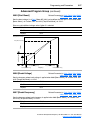
1
Adjustable
Frequency AC
Drive
FRN 1.xx - 6.xx
User Manual
www.abpowerflex.com
Chapter 3
Programming and Parameters
Chapter 3 provides a complete listing and description of the PowerFlex
40 parameters. Parameters are programmed (viewed/edited) using the
integral keypad. As an alternative, programming can also be performed
using DriveExplorer™ or DriveExecutive™ software, a personal
computer and a serial converter module. Refer to Appendix B for catalog
numbers.
For information on…
About Parameters
Parameter Organization
Basic Program Group
Advanced Program Group
Parameter Cross Reference – by Name
See page…
3-1
3-2
3-9
3-14
3-45
About Parameters
To configure a drive to operate in a specific way, drive parameters may
have to be set. Three types of parameters exist:
•
ENUM
ENUM parameters allow a selection from 2 or more items. Each
item is represented by a number.
•
Numeric Parameters
These parameters have a single numerical value (i.e. 0.1 Volts).
•
Bit Parameters
Bit parameters have four individual bits associated with features or
conditions. If the bit is 0, the feature is off or the condition is false. If
the bit is 1, the feature is on or the condition is true.
Some parameters are marked as follows.
= Stop drive before changing this parameter.
32
= 32 bit parameter. Parameters marked 32 bit will have two
parameter numbers when using RS485 communications and
programming software.
PowerFlex 40 Adjustable Frequency AC Drive FRN 1.xx - 6.xx User Manual
Publication 22B-UM001G-EN-E
3-2
Programming and Parameters
Parameter Organization
Refer to page 3-45 for an alphabetical listing of parameters.
Displa
y Gro
A
Progdravanced
m Gro
up
up
See page 3-3
Output Freq
Commanded Freq
Output Current
Output Voltage
DC Bus Voltage
Drive Status
Fault 1 Code
Fault 2 Code
Fault 3 Code
Process Display
Control Source
Contrl In Status
Dig In Status
Comm Status
Control SW Ver
Drive Type
Elapsed Run Time
Testpoint Data
Analog In 0-10V
Analog In 4-20mA
Output Power
Output Power Fctr
Drive Temp
Counter Status
Timer Status
Stp Logic Status
Torque Current
d001
d002
d003
d004
d005
d006
d007
d008
d009
d010
d012
d013
d014
d015
d016
d017
d018
d019
d020
d021
d022
d023
d024
d025
d026
d028
d029
Basic
Progra
m Gro
up
See page 3-9
Motor NP Volts
Motor NP Hertz
Motor OL Current
Minimum Freq
Maximum Freq
Start Source
Stop Mode
Speed Reference
Accel Time 1
Decel Time 1
Reset To Defalts
Voltage Class
Motor OL Ret
P031
P032
P033
P034
P035
P036
P037
P038
P039
P040
P041
P042
P043
See page 3-14
Digital In1 Sel
Digital In2 Sel
Digital In3 Sel
Digital In4 Sel
Relay Out Sel
Relay Out Level
Opto Out1 Sel
Opto Out1 Level
Opto Out2 Sel
Opto Out2 Level
Opto Out Logic
Analog Out Sel
Analog Out High
Accel Time 2
Decel Time 2
Internal Freq
Preset Freq 0
Preset Freq 1
Preset Freq 2
Preset Freq 3
Preset Freq 4
Preset Freq 5
Preset Freq 6
Preset Freq 7
Jog Frequency
Jog Accel/Decel
DC Brake Time
DC Brake Level
DB Resistor Sel
S Curve %
Boost Select
Start Boost
Break Voltage
Break Frequency
Maximum Voltage
Current Limit 1
Motor OL Select
PWM Frequency
Auto Rstrt Tries
Auto Rstrt Delay
Start At PowerUp
Reverse Disable
Flying Start En
Compensation
SW Current Trip
Process Factor
Fault Clear
Program Lock
Testpoint Sel
Comm Data Rate
Comm Node Addr
Comm Loss Action
A051
A052
A053
A054
A055
A056
A058
A059
A061
A062
A064
A065
A066
A067
A068
A069
A070
A071
A072
A073
A074
A075
A076
A077
A078
A079
A080
A081
A082
A083
A084
A085
A086
A087
A088
A089
A090
A091
A092
A093
A094
A095
A096
A097
A098
A099
A100
A101
A102
A103
A104
A105
PowerFlex 40 Adjustable Frequency AC Drive FRN 1.xx - 6.xx User Manual
Publication 22B-UM001G-EN-E
See page 3-14
Comm Loss Time
Comm Format
Language
Anlg Out Setpt
Anlg In 0-10V Lo
Anlg In 0-10V Hi
Anlg In4-20mA Lo
Anlg In4-20mA Hi
Slip Hertz @ FLA
Process Time Lo
Process Time Hi
Bus Reg Mode
Current Limit 2
Skip Frequency
Skip Freq Band
Stall Fault Time
Analog In Loss
10V Bipolar Enbl
Var PWM Disable
Torque Perf Mode
Motor NP FLA
Autotune
IR Voltage Drop
Flux Current Ref
PID Trim Hi
PID Trim Lo
PID Ref Sel
PID Feedback Sel
PID Prop Gain
PID Integ Time
PID Diff Rate
PID Setpoint
PID Deadband
PID Preload
Stp Logic 0
Stp Logic 1
Stp Logic 2
Stp Logic 3
Stp Logic 4
Stp Logic 5
Stp Logic 6
Stp Logic 7
Stp Logic Time 0
Stp Logic Time 1
Stp Logic Time 2
Stp Logic Time 3
Stp Logic Time 4
Stp Logic Time 5
Stp Logic Time 6
Stp Logic Time 7
EM Brk Off Delay
EM Brk On Delay
MOP Reset Sel
DB Threshold
Comm Write Mode
Anlg Loss Delay
Analog In Filter
PID Invert Error
A106
A107
A108
A109
A110
A111
A112
A113
A114
A115
A116
A117
A118
A119
A120
A121
A122
A123
A124
A125
A126
A127
A128
A129
A130
A131
A132
A133
A134
A135
A136
A137
A138
A139
A140
A141
A142
A143
A144
A145
A146
A147
A150
A151
A152
A153
A154
A155
A156
A157
A160
A161
A162
A163
A164
A165
A166
A167
Programming and Parameters
3-3
Display Group
d001 [Output Freq]
Related Parameter(s): d002, d010, P034, P035, P038
Output frequency present at T1, T2 & T3 (U, V & W).
Values
Default:
Read Only
Min/Max:
0.0/P035 [Maximum Freq]
Display:
0.1 Hz
d002 [Commanded Freq]
Related Parameter(s): d001, d013, P034, P035, P038
Value of the active frequency command. Displays the commanded frequency even if the drive is not
running.
Important: The frequency command can come from a number of sources. Refer to Start and Speed
Reference Control on page 1-23 for details.
Values
Default:
Read Only
Min/Max:
0.0/P035 [Maximum Freq]
Display:
0.1 Hz
d003 [Output Current]
The output current present at T1, T2 & T3 (U, V & W).
Values
Default:
Read Only
Min/Max:
0.00/(Drive Rated Amps × 2)
Display:
0.01 Amps
d004 [Output Voltage]
Related Parameter(s): P031, A084, A088
Output voltage present at terminals T1, T2 & T3 (U, V & W).
Values
Default:
Read Only
Min/Max:
0/Drive Rated Volts
Display:
1 VAC
d005 [DC Bus Voltage]
Present DC bus voltage level.
Values
Default:
Read Only
Min/Max:
Based on Drive Rating
Display:
1 VDC
PowerFlex 40 Adjustable Frequency AC Drive FRN 1.xx - 6.xx User Manual
Publication 22B-UM001G-EN-E
3-4
Programming and Parameters
Display Group (continued)
d006 [Drive Status]
Related Parameter(s): A095
Present operating condition of the drive.
Running
Forward
Accelerating
Decelerating
Values
Default:
1 = Condition True, 0 = Condition False
Bit 0
Bit 1
Bit 2
Bit 3
Read Only
Min/Max:
0/1
Display:
1
d007 [Fault 1 Code]
d008 [Fault 2 Code]
d009 [Fault 3 Code]
A code that represents a drive fault. The codes will appear in these parameters in the order they occur
(d007 [Fault 1 Code] = the most recent fault). Repetitive faults will only be recorded once.
Refer to Chapter 4 for fault code descriptions.
Values
Default:
Read Only
Min/Max:
F2/F122
Display:
F1
d010 [Process Display]
32
Related Parameter(s): d001, A099
32 bit parameter.
The output frequency scaled by A099 [Process Factor].
Output
Process
Process
Freq x Factor = Display
Values
Default:
Read Only
Min/Max:
0.00/9999
Display:
0.01 – 1
PowerFlex 40 Adjustable Frequency AC Drive FRN 1.xx - 6.xx User Manual
Publication 22B-UM001G-EN-E
Programming and Parameters
3-5
Display Group (continued)
d012 [Control Source]
Related Parameter(s): P036, P038, A051-A054
Displays the active source of the Start Command and Speed Command which are normally defined
by the settings of P036 [Start Source] and P038 [Speed Reference] but may be overridden by digital
inputs. Refer to the flowcharts on pages 1-23 and 1-24 for details.
Start Command
Digit 0
0 = Keypad
1 = 3-Wire
2 = 2-Wire
3 = 2-Wire Level Sensitive
4 = 2-Wire High Speed
5 = RS485 (DSI) Port
9 = Jog
Speed Command
Digit 1
0 = Drive Potentiometer
1 = A069 [Internal Freq]
2 = 0-10V Input/Remote Potentiometer
3 = 4-20mA Input
4 = A070-A077 [Preset Freq x]
(A051 - A053 [Digital Inx Sel] must be set to 4)
5 = RS485 (DSI) Port
6 = StepLogic Control (Parameters A140 - A147)
7 = Anlg In Mult
8 = PID
9 = Jog Freq
Reserved
Digit 2
Reserved
Digit 3
Values
Default:
Read Only
Min/Max:
0/9
Display:
1
d013 [Contrl In Status]
Related Parameter(s): d002, P034, P035
Status of the control terminal block control inputs.
Important: Actual control commands may come from a source other than the control terminal block.
1 = Input Present, 0 = Input Not Present
Start / Run FWD Input (I/O Terminal 02)
Bit 0
Direction / Run REV Input (I/O Terminal 03)
Bit 1
Bit 2
Stop Input(1) (I/O Terminal 01)
Dynamic Brake Transistor On
Bit 3
(1)
The stop input must be present in order to start the drive.
When this bit is a 1 the drive can be started.
When this bit is a 0 the drive will stop.
Values
Default:
Read Only
Min/Max:
0/1
Display:
1
PowerFlex 40 Adjustable Frequency AC Drive FRN 1.xx - 6.xx User Manual
Publication 22B-UM001G-EN-E
3-6
Programming and Parameters
Display Group (continued)
d014 [Dig In Status]
Related Parameter(s): A051-A054
Status of the control terminal block digital inputs.
1 = Input Present, 0 = Input Not Present
Digital In1 Sel (I/O Terminal 05)
Bit 0
Digital In2 Sel (I/O Terminal 06)
Bit 1
Digital In3 Sel (I/O Terminal 07)
Bit 2
Digital In4 Sel (I/O Terminal 08)
Bit 3
Values
Default:
Read Only
Min/Max:
0/1
Display:
1
d015 [Comm Status]
Related Parameter(s): A103-A107
Status of the communications ports.
1 = Condition True, 0 = Condition False
Receiving Data
Bit 0
Transmitting Data
Bit 1
RS485 (DSI) Based Option Connected
Bit 2
(Allen-Bradley devices only.)
Communication Error Occurred
Bit 3
Values
Default:
Read Only
Min/Max:
0/1
Display:
1
d016 [Control SW Ver]
Main Control Board software version.
Values
Default:
Read Only
Min/Max:
1.00/99.99
Display:
0.01
d017 [Drive Type]
Used by Rockwell Automation field service personnel.
Values
Default:
Read Only
Min/Max:
1001/9999
Display:
1
PowerFlex 40 Adjustable Frequency AC Drive FRN 1.xx - 6.xx User Manual
Publication 22B-UM001G-EN-E
Programming and Parameters
3-7
Display Group (continued)
d018 [Elapsed Run Time]
Accumulated time drive is outputting power. Time is displayed in 10 hour increments.
Values
Default:
Read Only
Min/Max:
0/9999 Hrs
Display:
1 = 10 Hrs
d019 [Testpoint Data]
Related Parameter(s): A102
The present value of the function selected in A102 [Testpoint Sel].
Values
Default:
Read Only
Min/Max:
0/FFFF
Display:
1 Hex
d020 [Analog In 0-10V]
Related Parameter(s): A110, A111
The present value of the voltage at I/O Terminal 13 (100.0% = 10 volts).
Values
Default:
Read Only
Min/Max:
0.0/100.0%
Display:
0.1%
d021 [Analog In 4-20mA]
Related Parameter(s): A112, A113
The present value of the current at I/O Terminal 15 (0.0% = 4mA, 100.0% = 20mA).
Values
Default:
Read Only
Min/Max:
0.0/100.0%
Display:
0.1%
d022 [Output Power]
Output power present at T1, T2 & T3 (U, V & W).
Values
Default:
Read Only
Min/Max:
0.00/(Drive Rated Power × 2)
Display:
0.01 kW
d023 [Output Powr Fctr]
The angle in electrical degrees between motor voltage and motor current.
Values
Default:
Read Only
Min/Max:
0.0/180.0 deg
Display:
0.1 deg
PowerFlex 40 Adjustable Frequency AC Drive FRN 1.xx - 6.xx User Manual
Publication 22B-UM001G-EN-E
3-8
Programming and Parameters
Display Group (continued)
d024 [Drive Temp]
Present operating temperature of the drive power section.
Values
Default:
Read Only
Min/Max:
0/120 degC
Display:
1 degC
d025 [Counter Status]
The current value of the counter when counter is enabled.
Values
Default:
Read only
Min/Max:
0/9999
Display:
1
d026 [Timer Status]
32
32 bit parameter.
The current value of the timer when timer is enabled.
Values
Default:
Read Only
Min/Max:
0.0/9999 Secs
Display:
0.1 Secs
d028 [Stp Logic Status]
When P038 [Speed Reference] is set to 6 “Stp Logic”, this parameter will display the current step of
the StepLogic profile as defined by parameters A140-A147 [Stp Logic x].
Values
Default:
Read Only
Min/Max:
0/7
Display:
1
d029 [Torque Current]
The current value of the motor torque current.
Values
Default:
Read Only
Min/Max:
0.00/(Drive Rated Amps × 2)
Display:
0.01 Amps
PowerFlex 40 Adjustable Frequency AC Drive FRN 1.xx - 6.xx User Manual
Publication 22B-UM001G-EN-E
Programming and Parameters
3-9
Basic Program Group
P031 [Motor NP Volts]
Related Parameter(s): d004, A084, A085, A086, A087
Stop drive before changing this parameter.
Set to the motor nameplate rated volts.
Values
Default:
Based on Drive Rating
Min/Max:
20/Drive Rated Volts
Display:
1 VAC
P032 [Motor NP Hertz]
Related Parameter(s): A084, A085, A086, A087, A090
Stop drive before changing this parameter.
Set to the motor nameplate rated frequency.
Values
Default:
60 Hz
Min/Max:
15/400 Hz
Display:
1 Hz
P033 [Motor OL Current]
Related Parameter(s): A055, A058, A061, A089, A090,
A098, A114, A118
Set to the maximum allowable motor current.
The drive will fault on an F7 Motor Overload if the value of this parameter is exceeded by 150% for 60
seconds.
Values
Default:
Based on Drive Rating
Min/Max:
0.0/(Drive Rated Amps × 2)
Display:
0.1 Amps
P034 [Minimum Freq]
Related Parameter(s): d001, d002, d013, P035, A085,
A086, A087, A110, A112
Sets the lowest frequency the drive will output continuously.
Values
Default:
0.0 Hz
Min/Max:
0.0/400.0 Hz
Display:
0.1 Hz
P035 [Maximum Freq]
Related Parameter(s): d001, d002, d013, P034, A065,
A078, A085, A086, A087, A111, A113
Stop drive before changing this parameter.
Sets the highest frequency the drive will output.
Values
Default:
60 Hz
Min/Max:
0/400 Hz
Display:
1 Hz
PowerFlex 40 Adjustable Frequency AC Drive FRN 1.xx - 6.xx User Manual
Publication 22B-UM001G-EN-E
3-10
Programming and Parameters
Basic Program Group (continued)
P036 [Start Source]
Related Parameter(s): d012, P037
Stop drive before changing this parameter.
Sets the control scheme used to start the drive.
Refer to Start and Speed Reference Control on page 1-23 for details about how other drive settings
can override the setting of this parameter.
Important: For all settings except option 3, the drive must receive a leading edge from the start input
for the drive to start after a stop input, loss of power or fault condition.
Options 0 “Keypad” (Default)
• Integral keypad controls drive operation.
• I/O Terminal 1 “Stop” = coast to stop.
• When active, the Reverse key is also active unless
disabled by A095 [Reverse Disable].
1 “3-Wire”
I/O Terminal 1 “Stop” = stop according to the value set in
P037 [Stop Mode].
2 “2-Wire”
I/O Terminal 1 “Stop” = coast to stop.
3 “2-W Lvl Sens”
Drive will restart after a “Stop” command when:
• Stop is removed
and
• Start is held active
!
ATTENTION: Hazard of injury exists due to unintended operation.
When P036 [Start Source] is set to option 3, and the Run input is
maintained, the Run inputs do not need to be toggled after a Stop input for
the drive to run again. A Stop function is provided only when the Stop input
is active (open).
4 “2-W Hi Speed”
Important: There is greater potential voltage on the output
terminals when using this option.
• Outputs are kept in a ready-to-run state. The drive will
respond to a “Start” command within 10 ms.
• I/O Terminal 1 “Stop” = coast to stop.
5 “Comm Port”
• Remote communications. Refer to Appendix C for details.
• I/O Terminal 1 “Stop” = coast to stop.
6 “Momt FWD/REV”
• Drive will start after a momentary input from either the
Run FWD Input (I/O Terminal 02) or the Run REV Input (I/
O Terminal 03).
• I/O Terminal 1 “Stop” = coast to stop.
PowerFlex 40 Adjustable Frequency AC Drive FRN 1.xx - 6.xx User Manual
Publication 22B-UM001G-EN-E
Programming and Parameters
3-11
Basic Program Group (continued)
P037 [Stop Mode]
Related Parameter(s): P036, A080, A081, A082, A105, A160
Active stop mode for all stop sources [e.g. keypad, run forward (I/O Terminal 02), run reverse (I/O
Terminal 03), RS485 port] except as noted below.
Important: I/O Terminal 01 is always a coast to stop input except when P036 [Start Source] is set for
“3-Wire” control. When in three wire control, I/O Terminal 01 is controlled by P037 [Stop Mode].
Hardware Enable Circuitry
By default, I/O Terminal 01 is a coast to stop input. The status of the input is interpreted by drive
software. If the application requires the drive to be disabled without software interpretation, a “dedicated” hardware enable configuration can be utilized. This is accomplished by removing the ENBL
enable jumper on the control board. In this case, the drive will always coast to a stop regardless of the
settings of P036 [Start Source] and P037 [Stop Mode].
Options 0 “Ramp, CF”(1) (Default) Ramp to Stop. “Stop” command clears active fault.
1 “Coast, CF”(1)
Coast to Stop. “Stop” command clears active fault.
2 “DC Brake, CF”(1)
DC Injection Braking Stop. “Stop” command clears active
fault.
3 “DCBrkAuto,CF”(1)
DC Injection Braking Stop with Auto Shutoff.
• Standard DC Injection Braking for value set in A080 [DC
Brake Time].
OR
• Drive shuts off if the drive detects that the motor is
stopped.
“Stop” command clears active fault.
4 “Ramp”
Ramp to Stop.
5 “Coast”
Coast to Stop.
6 “DC Brake”
DC Injection Braking Stop.
7 “DC BrakeAuto”
DC Injection Braking Stop with Auto Shutoff.
• Standard DC Injection Braking for value set in A080 [DC
Brake Time].
OR
• Drive shuts off if current limit is exceeded.
(1)
8 “Ramp+EM B,CF”
Ramp to Stop with EM Brake Control. “Stop” Command
clears active fault.
9 “Ramp+EM Brk”
Ramp to Stop with EM Brake Control.
Stop input also clears active fault.
PowerFlex 40 Adjustable Frequency AC Drive FRN 1.xx - 6.xx User Manual
Publication 22B-UM001G-EN-E
3-12
Programming and Parameters
Basic Program Group (continued)
P038 [Speed Reference] Related Parameter(s): d001, d002, d012, d020, d021, P039, P040,
A051-A054, A069, A070-A077, A110-A113, A123, A132, A140-A147, A150-A157
Sets the source of the speed reference to the drive.
The drive speed command can be obtained from a number of different sources. The source is
normally determined by P038 [Speed Reference]. However, when A051 - A054 [Digital Inx Sel] is set
to option 2, 4, 5, 6, 11, 12, 13, 14, 15 and the digital input is active, or if A132 [PID Ref Sel] is not set
to option 0, the speed reference commanded by P038 [Speed Reference] will be overridden. Refer to
the flowchart on page 1-23 for more information on speed reference control priority.
Options 0 “Drive Pot” (Default)
Frequency command from the potentiometer on the integral
keypad.
Important: This option is not available with IP66, NEMA/UL
Type 4X rated drives. Internal frequency command comes
from A069 [Internal Freq].
1 “InternalFreq”
(IP66, NEMA/UL Type
4X Default)
Internal frequency command from A069 [Internal Freq]. Must
be set when using MOP function.
2 “0-10V Input”
External frequency command from the 0-10V or ±10V analog
input or remote potentiometer.
3 “4-20mA Input”
External frequency command from the 4-20mA analog input.
4 “Preset Freq”
External frequency command as defined by A070 - A077
[Preset Freq x] when A051 - A054 [Digital Inx Sel] are
programmed as “Preset Frequencies” and the digital inputs
are active.
5 “Comm Port”
External frequency command from the communications port.
Refer to Appendix C for details.
6 “Stp Logic”
External frequency command as defined by A070 - A077
[Preset Freq x] and A140 - A147 [Stp Logic x].
7 “Anlg In Mult”
External frequency command as defined by the product of the
analog inputs (shown in d020 [Analog In 0-10V] and d021
[Analog In 4-20mA]).
[Analog In 0-10V] × [Analog In 4-20mA] = Speed Command
Example: 100% × 50% = 50%
P039 [Accel Time 1]
Related Parameter(s): P038, P040, A051-A054,
A067, A070-A077, A140-A147
Sets the rate of acceleration for all speed increases.
Maximum Freq
= Accel Rate
Accel Time
Values
Default:
10.0 Secs
Min/Max:
0.0/600.0 Secs
Display:
0.1 Secs
P035 [Maximum Freq]
0
0
P039 or A067
[Accel Time x]
n
Ac
c
tio
ele
a
ler
rat
i
ce
on
De
Speed
Time
P040 or A068
[Decel Time x]
PowerFlex 40 Adjustable Frequency AC Drive FRN 1.xx - 6.xx User Manual
Publication 22B-UM001G-EN-E
Programming and Parameters
3-13
Basic Program Group (continued)
P040 [Decel Time 1]
Related Parameter(s): P038, P039, A051-A054,
A068, A070-A077, A140-A147
Sets the rate of deceleration for all speed decreases.
Maximum Freq
= Decel Rate
Decel Time
Values
Default:
10.0 Secs
Min/Max:
0.1/600.0 Secs
Display:
0.1 Secs
P035 [Maximum Freq]
Ac
on
ce
i
rat
ler
a
le
ce
tio
n
De
Speed
0
0
P039 or A067
[Accel Time x]
Time
P040 or A068
[Decel Time x]
P041 [Reset To Defalts]
Stop drive before changing this parameter.
Resets all parameter values to factory defaults.
Options 0 “Ready/Idle” (Default)
• After the reset function is complete, this parameter will set
itself back to “0”.
• Causes an F48 Params Defaulted fault.
1 “Factory Rset”
P042 [Voltage Class]
Stop drive before changing this parameter.
Sets the voltage class of 600V drives.
Options 2 “Low Voltage”
480V
3 “High Voltage”
(Default)
600V
P043 [Motor OL Ret]
Related Parameter(s): P033
Enables/disables the Motor Overload Retention function. When Enabled, the value held in the motor
overload counter is saved at power-down and restored at power-up. A change to this parameter
setting resets the counter.
Options 0 “Disabled” (Default)
1 “Enabled”
PowerFlex 40 Adjustable Frequency AC Drive FRN 1.xx - 6.xx User Manual
Publication 22B-UM001G-EN-E
3-14
Programming and Parameters
Advanced Program Group
A051 [Digital In1 Sel]
(I/O Terminal 05)
Related Parameter(s): d012, d014, P038, P039, P040,
A067, A068, A070-A077, A078, A079, A118, A140-A147
A052 [Digital In2 Sel]
(I/O Terminal 06)
A053 [Digital In3 Sel]
Stop drive before changing this parameter.
(I/O Terminal 07)
A054 [Digital In4 Sel]
(I/O Terminal 08)
Selects the function for the digital inputs. Refer to the flowchart on page 1-23 for more information on
speed reference control priority.
Options 0 “Not Used”
Terminal has no function but can be read over network
communications via d014 [Dig In Status].
• When active, A067 [Accel Time 2] and A068 [Decel Time
2] are used for all ramp rates except Jog.
• Can only be tied to one input.
Refer to the flowchart on page 1-24 for more information on
Accel/Decel selection.
2 “Jog”
• When input is present, drive accelerates according to the
value set in A079 [Jog Accel/Decel] and ramps to the
value set in A078 [Jog Frequency].
• When input is removed, drive ramps to a stop according to
the value set in A079 [Jog Accel/Decel].
• A valid “Start” command will override this input.
3 “Aux Fault”
When enabled, an F2 Auxiliary Input fault will occur when the
input is removed.
4 “Preset Freq”
Refer to A070 - A077 [Preset Freq x].
(A051 & A052 Default) Important: Digital Inputs have priority for frequency control
when programmed as Preset Speed and are active. Refer to
the flowchart on page 1-23 for more information on speed
reference control priority.
5 “Local”
When active, sets integral keypad as start source and
(A053 Default)
potentiometer on the integral keypad as speed source.
Important: Speed source for IP66, NEMA/UL Type 4X rated
drives comes from A069 [Internal Freq].
6 “Comm Port”
• When active, sets communications device as default start/
speed command source.
• Can only be tied to one input.
7 “Clear Fault”
When active, clears an active fault.
8 “RampStop,CF”
Causes drive to immediately ramp to a stop regardless of how
P037 [Stop Mode] is set.
9 “CoastStop,CF”
Causes drive to immediately coast to a stop regardless of
how P037 [Stop Mode] is set.
10 “DCInjStop,CF”
Causes drive to immediately begin a DC Injection stop
regardless of how P037 [Stop Mode] is set.
11 “Jog Forward”
Drive accelerates to A078 [Jog Frequency] according to A079
(A054 Default)
[Jog Accel/Decel] and ramps to stop when input becomes
inactive. A valid start will override this command.
12 “Jog Reverse”
Drive accelerates to A078 [Jog Frequency] according to A079
[Jog Accel/Decel] and ramps to stop when input becomes
inactive. A valid start will override this command.
1 “Acc & Dec 2”
PowerFlex 40 Adjustable Frequency AC Drive FRN 1.xx - 6.xx User Manual
Publication 22B-UM001G-EN-E
Programming and Parameters
13 “10V In Ctrl”
A051 A054
Options 14 “20mA In Ctrl”
(Cont.)
15 “PID Disable”
16 “MOP Up”
17 “MOP Down”
18 “Timer Start”
19 “Counter In”
20
21
22
23
“Reset Timer”
“Reset Countr”
“Rset Tim&Cnt”
“Logic In1”
24 “Logic In2”
25 “Current Lmt2”
26 “Anlg Invert”
27 “EM Brk Rlse”
!
3-15
Selects 0-10V or ±10V control as the frequency reference.
Start source is not changed.
Selects 4-20mA control as the frequency reference. Start
source is not changed.
Disables PID function. Drive uses the next valid non-PID
speed reference.
Increases the value of A069 [Internal Freq] at the current
Accel rate if P038 [Speed Reference] is set to 1
“InternalFreq”.
For IP20 rated drives, the default for A069 is 60.0 Hz.
For IP66, NEMA/UL Type 4X drives, the default for A069 is
0.0 Hz.
Decreases the value of A069 [Internal Freq] at the current
Decel rate if P038 [Speed Reference] is set to 1
“InternalFreq”.
For IP20 rated drives, the default for A069 is 60.0 Hz.
For IP66, NEMA/UL Type 4X drives, the default for A069 is
0.0 Hz.
Clears and starts the timer function. May be used to control
the relay or opto outputs.
Starts the counter function. May be used to control the relay
or opto outputs.
Clears the active timer.
Clears the active counter.
Clears the active timer and counter.
Logic function input number 1. May be used to control the
relay or opto outputs (see parameters A055, A058, A061
Options 11-14). May be used in conjunction with StepLogic
parameters A140 - A147 [Stp Logic x].
Logic function input number 2. May be used to control the
relay or opto outputs (see parameters A055, A058, A061
Options 11-14). May be used in conjunction with StepLogic
parameters A140 - A147 [Stp Logic x].
When active, A118 [Current Limit 2] determines the drive
current limit level.
Inverts the scaling of the analog input levels set in
A110 [Anlg In 0-10V Lo] and A111 [Anlg In 0-10V Hi] or
A112 [Anlg In4-20mA Lo] and A113 [Anlg In4-20mA Hi].
If EM brake function is enabled, this input releases the brake.
ATTENTION: If a hazard of injury due to movement of equipment or
material exists, an auxiliary mechanical braking device must be used.
PowerFlex 40 Adjustable Frequency AC Drive FRN 1.xx - 6.xx User Manual
Publication 22B-UM001G-EN-E
3-16
Programming and Parameters
Advanced Program Group (continued)
A055 [Relay Out Sel]
Related Parameter(s): P033, A056, A092, A140-A147, A150-A157,
A160, A161
Sets the condition that changes the state of the output relay contacts.
Options 0 “Ready/Fault”
Relay changes state when power is applied. This indicates
that the drive is ready for operation. Relay returns drive to
(Default)
shelf state when power is removed or a fault occurs.
1 “At Frequency”
Drive reaches commanded frequency.
2 “MotorRunning”
Motor is receiving power from the drive.
3 “Reverse”
Drive is commanded to run in reverse direction.
4 “Motor Overld”
Motor overload condition exists.
5 “Ramp Reg”
Ramp regulator is modifying the programmed accel/decel
times to avoid an overcurrent or overvoltage fault from
occurring.
6 “Above Freq”
• Drive exceeds the frequency (Hz) value set in A056 [Relay
Out Level].
• Use A056 to set threshold.
• Drive exceeds the current (% Amps) value set in A056
[Relay Out Level].
• Use A056 to set threshold.
7 “Above Cur”
8 “Above DCVolt”
9 “Retries Exst”
10 “Above Anlg V”
11 “Logic In 1”
Important: Value for A056 [Relay Out Level] must be entered
in percent of drive rated output current.
• Drive exceeds the DC bus voltage value set in A056
[Relay Out Level].
• Use A056 to set threshold.
Value set in A092 [Auto Rstrt Tries] is exceeded.
• Analog input voltage (I/O Terminal 13) exceeds the value
set in A056 [Relay Out Level].
• Do not use if A123 [10V Bipolar Enbl] is set to 1 “Bi-Polar In”.
• This parameter setting can also be used to indicate a PTC
trip point when the input (I/O Terminal 13) is wired to a
PTC and external resistor.
• Use A056 to set threshold.
An input is programmed as “Logic In 1” and is active.
12 “Logic In 2”
An input is programmed as “Logic In 2” and is active.
13 “Logic 1 & 2”
Both Logic inputs are programmed and active.
14 “Logic 1 or 2”
One or both Logic inputs are programmed and one or both is
active.
15 “StpLogic Out”
Drive enters StepLogic step with Digit 3 of Command Word
(A140 - A147) set to enable StepLogic output.
16 “Timer Out”
•
•
•
•
•
17 “Counter Out”
18 “Above PF Ang”
Timer has reached value set in A056 [Relay Out Level].
Use A056 to set threshold.
Counter has reached value set in A056 [Relay Out Level].
Use A056 to set threshold.
Power Factor angle has exceeded the value set in A056
[Relay Out Level].
• Use A056 to set threshold.
PowerFlex 40 Adjustable Frequency AC Drive FRN 1.xx - 6.xx User Manual
Publication 22B-UM001G-EN-E
Programming and Parameters
A055
19 “Anlg In Loss”
Options
(Cont.)
20 “ParamControl”
3-17
Analog input loss has occurred. Program A122 [Analog In
Loss] for desired action when input loss occurs.
Prior to FRN 4.01, this option enables the output to be
controlled over network communications by writing to A056
[Relay Out Level]. (0 = Off, 1 = On.)
With FRN 4.01 and later, the logic command word bit 15 has
full control of A056. See Writing (06) Logic Command
Data on page C-4.
21 “NonRec Fault”
22 “EM Brk Cntrl”
• Value set in A092 [Auto Rstrt Tries] is exceeded.
• A092 [Auto Rstrt Tries] in not enabled.
• A Non-resettable fault has occurred.
EM brake is energized. Program A160 [EM Brk Off Delay] and
A161 [EM Brk On Delay] for desired action.
23 “Above Fcmd”
The current commanded frequency exceeds the value set in
A056 [Relay Out Level].
24 “MsgControl”
With FRN 4.01 and later, this option enables the output to be
controlled over network communications by writing to A056
[Relay Out Level]. (0 = Off, 1 = On.)
A056 [Relay Out Level]
32
Related Parameter(s): A055
32 bit parameter.
Sets the trip point for the digital output relay if the value of A055 [Relay Out Sel] is 6, 7, 8, 10, 16, 17,
18 or 20.
With FRN 4.01 and later, when the value of A055 is set to 20, the logic command word bit 15 has full
control of A056.
A055 Setting
6
7
8
10
16
17
18
20
23
Values
Default:
A056 Min/Max
0/400 Hz
0/180%
0/815 Volts
0/100%
0.1/9999 Secs
1/9999 Counts
1/180 degs
0/1
0/400 Hz
0.0
Min/Max:
0.0/9999
Display:
0.1
PowerFlex 40 Adjustable Frequency AC Drive FRN 1.xx - 6.xx User Manual
Publication 22B-UM001G-EN-E
3-18
Programming and Parameters
Advanced Program Group (continued)
A058 [Opto Out1 Sel]
A061 [Opto Out2 Sel]
Related Parameter(s): P033, A059, A062, A092, A122, A123,
A160, A161, A140-A147, A150-A157
Determines the operation of the programmable opto outputs.
Options 0 “Ready/Fault”
Opto outputs are active when power is applied. This indicates
that the drive is ready for operation. Opto outputs are inactive
when power is removed or a fault occurs.
1 “At Frequency”
(A061 Default)
2 “MotorRunning”
(A058 Default)
3 “Reverse”
Drive reaches commanded frequency.
Motor is receiving power from the drive.
Drive is commanded to run in reverse direction.
4 “Motor Overld”
Motor overload condition exists.
5 “Ramp Reg”
Ramp regulator is modifying the programmed accel/decel
times to avoid an overcurrent or overvoltage fault from
occurring.
6 “Above Freq”
• Drive exceeds the frequency (Hz) value set in A059 or
A062 [Opto Outx Level].
• Use A059 or A062 to set threshold.
• Drive exceeds the current (% Amps) value set in A059 or
A062 [Opto Outx Level].
• Use A059 or A062 to set threshold.
7 “Above Cur”
8 “Above DCVolt”
9 “Retries Exst”
10 “Above Anlg V”
11 “Logic In 1”
Important: Value for A059 or A062 [Opto Outx Level] must be
entered in percent of drive rated output current.
• Drive exceeds the DC bus voltage value set in A059 or
A062 [Opto Outx Level].
• Use A059 or A062 to set threshold.
Value set in A092 [Auto Rstrt Tries] is exceeded.
• Analog input voltage (I/O Terminal 13) exceeds the value
set in A059 or A062 [Opto Outx Level].
• Do not use if A123 [10V Bipolar Enbl] is set to 1 “Bi-Polar
In”.
• This parameter setting can also be used to indicate a PTC
trip point when the input (I/O Terminal 13) is wired to a
PTC and external resistor.
• Use A059 or A062 to set threshold.
An input is programmed as “Logic In 1” and is active.
12 “Logic In 2”
An input is programmed as “Logic In 2” and is active.
13 “Logic 1 & 2”
Both Logic inputs are programmed and active.
14 “Logic 1 or 2”
One or both Logic inputs are programmed and one or both is
active.
15 “StpLogic Out”
Drive enters StepLogic step with Digit 3 of Command Word
(A140 - A147) set to enable StepLogic output.
16 “Timer Out”
• Timer has reached value set in A059 or A062 [Opto Outx
Level].
• Use A059 or A062 to set threshold.
• Counter has reached value set in A059 or A062 [Opto
Outx Level].
• Use A059 or A062 to set threshold.
17 “Counter Out”
PowerFlex 40 Adjustable Frequency AC Drive FRN 1.xx - 6.xx User Manual
Publication 22B-UM001G-EN-E
Programming and Parameters
3-19
18 “Above PF Ang”
A058,
A061
Options
(Cont.)
19 “Anlg In Loss”
• Power Factor angle has exceeded the value set in A059 or
A062 [Opto Outx Level].
• Use A059 or A062 to set threshold.
Analog input loss has occurred. Program A122 [Analog In
Loss] for desired action when input loss occurs.
20 “ParamControl”
Prior to FRN 4.01, this option enables the output to be
controlled over network communications by writing to A059 or
A062 [Opto Outx Level]. (0 = Off, 1 = On.)
With FRN 4.01 and later:
Setting this option for A058 means the logic command word
bit 6 has full control of A059.
Setting this option for A059 means the logic command word
bit 7 has full control of A062.
See Writing (06) Logic Command Data on page C-4.
21 “NonRec Fault”
22 “EM Brk Cntrl”
• Value set in A092 [Auto Rstrt Tries] is exceeded.
• A092 [Auto Rstrt Tries] in not enabled.
• A Non-resettable fault has occurred.
EM brake is energized. Program A160 [EM Brk Off Delay] and
A161 [EM Brk On Delay] for desired action.
23 “Above Fcmd”
The current commanded frequency exceeds the value set in
A059 or A062 [Opto Outx Level].
24 “MsgControl”
With FRN 4.01 and later:
Enables the output to be controlled over the network
communications by writing to A059 or A062 [Opto Outx
Level]. (0 = Off, 1 = On.)
A059 [Opto Out1 Level]
A062 [Opto Out2 Level]
32
Related Parameter(s): A058, A061
32 bit parameter.
Determines the on/off point for the opto outputs when A058 or A061 [Opto Outx Sel] is set to option 6,
7, 8, 10, 16, 17, 18 or 20.
With FRN 4.01 and later, when the value of A058 is set to 20, the logic command word bit 6 has full
control of A059 and when the value of A061 is set to 20, bit 7 has full control of A062.
A058 & A061 Setting
6
7
8
10
16
17
18
20
23
Values
Default:
A059 & A062 Min/Max
0/400 Hz
0/180%
0/815 Volts
0/100%
0.1/9999 Secs
1/9999 Counts
1/180 degs
0/1
0/400 Hz
0.0
Min/Max:
0.0/9999
Display:
0.1
PowerFlex 40 Adjustable Frequency AC Drive FRN 1.xx - 6.xx User Manual
Publication 22B-UM001G-EN-E
3-20
Programming and Parameters
Advanced Program Group (continued)
A064 [Opto Out Logic]
Determines the logic (Normally Open/NO or Normally Closed/NC) of the opto outputs.
A064 Option
0
1
2
3
Values
Opto Out1 Logic
NO (Normally Open)
NC (Normally Closed)
NO (Normally Open)
NC (Normally Closed)
Default:
Opto Out2 Logic
NO (Normally Open)
NO (Normally Open)
NC (Normally Closed)
NC (Normally Closed)
0
Min/Max:
0/3
Display:
1
A065 [Analog Out Sel]
Related Parameter(s): P035, A066
Sets the analog output signal mode (0-10V, 0-20mA, or 4-20mA). The output is used to provide a
signal that is proportional to several drive conditions.
Option
0 “OutFreq 0-10”
1 “OutCurr 0-10”
2 “OutVolt 0-10”
3 “OutPowr 0-10”
4 “TstData 0-10”
5 “OutFreq 0-20”
6 “OutCurr 0-20”
7 “OutVolt 0-20”
8 “OutPowr 0-20”
9 “TstData 0-20”
10 “OutFreq 4-20”
11 “OutCurr 4-20”
12 “OutVolt 4-20”
13 “OutPowr 4-20”
14 “TstData 4-20”
15 “OutTorq 0-10”
16 “OutTorq 0-20”
17 “OutTorq 4-20”
18 “Setpnt 0-10”
19 “Setpnt 0-20”
20 “Setpnt 4-20”
21 “MinFreq 0-10”
22 “MinFreq 0-20”
23 “MinFreq 4-20”
Values
Output
Range
0-10V
0-10V
0-10V
0-10V
0-10V
0-20mA
0-20mA
0-20mA
0-20mA
0-20mA
4-20mA
4-20mA
4-20mA
4-20mA
4-20mA
0-10V
0-20 mA
4-20 mA
0-10V
0-20 mA
4-20 mA
0-10V
0-20 mA
4-20 mA
Default:
Minimum Output
Value
0V = 0 Hz
0V = 0 Amps
0V = 0 Volts
0V = 0 kW
0V = 0000
0 mA = 0 Hz
0 mA = 0 Amps
0 mA = 0 Volts
0 mA = 0 kW
0 mA = 0000
4 mA = 0 Hz
4 mA = 0 Amps
4 mA = 0 Volts
4 mA = 0 kW
4 mA = 0000
0V = 0 Amps
0 mA = 0 Amps
4 mA = 0 Amps
0V = 0%
0 mA = 0%
4 mA = 0%
0V = Min. Freq
0 mA = Min. Freq
4 mA = Min. Freq
Maximum Output Value
A066 [Analog Out High]
P035 [Maximum Freq]
200% Drive Rated Output Current
120% Drive Rated Output Volts
200% Drive Rated Power
65535 (Hex FFFF)
P035 [Maximum Freq]
200% Drive Rated Output Current
120% Drive Rated Output Volts
200% Drive Rated Power
65535 (Hex FFFF)
P035 [Maximum Freq]
200% Drive Rated Output Current
120% Drive Rated Output Volts
200% Drive Rated Power
65535 (Hex FFFF)
200% Drive Rated FLA
200% Drive Rated FLA
200% Drive Rated FLA
100.0% Setpoint Setting
100.0% Setpoint Setting
100.0% Setpoint Setting
P035 [Maximum Freq]
P035 [Maximum Freq]
P035 [Maximum Freq]
0
Min/Max:
0/23
Display:
1
PowerFlex 40 Adjustable Frequency AC Drive FRN 1.xx - 6.xx User Manual
Publication 22B-UM001G-EN-E
DIP Switch
Position
0-10V
0-10V
0-10V
0-10V
0-10V
0-20mA
0-20mA
0-20mA
0-20mA
0-20mA
0-20mA
0-20mA
0-20mA
0-20mA
0-20mA
0-10V
0-20 mA
0-20 mA
0-10V
0-20 mA
0-20 mA
0-10V
0-20 mA
0-20 mA
Related
Parameter
d001
d003
d004
d022
d019
d001
d003
d004
d022
d019
d001
d003
d004
d022
d019
d029
d029
d029
A109
A109
A109
d001
d001
d001
Programming and Parameters
3-21
Advanced Program Group (continued)
A066 [Analog Out High]
Related Parameter(s): A065
Scales the Maximum Output Value for the A065 [Analog Out Sel] source setting.
Examples:
A066 Setting
50%
90%
Values
A065 Setting
1 “OutCurr 0-10”
8 “OutPowr 0-20”
A065 Max. Output Value
5V for 200% Drive Rated Output Current
18mA for 200% Drive Rated Power
Default:
100%
Min/Max:
0/800%
Display:
1%
A067 [Accel Time 2]
Related Parameter(s): P039, A051-A054, A070-A077, A140-A147
When active, sets the rate of acceleration for all speed increases except jog. Refer to the flowchart on
page 1-24 for details.
Maximum Freq
= Accel Rate
Accel Time
Values
Default:
20.0 Secs
Min/Max:
0.0/600.0 Secs
Display:
0.1 Secs
P035 [Maximum Freq]
Ac
on
ce
ati
ler
ler
ati
ce
on
De
Speed
0
0
P039 or A067
[Accel Time x]
Time
P040 or A068
[Decel Time x]
PowerFlex 40 Adjustable Frequency AC Drive FRN 1.xx - 6.xx User Manual
Publication 22B-UM001G-EN-E
3-22
Programming and Parameters
Advanced Program Group (continued)
A068 [Decel Time 2]
Related Parameter(s): P040, A051-A054, A070-A077, A140-A147
When active, sets the rate of deceleration for all speed decreases except jog. Refer to the flowchart
on page 1-24 for details.
Maximum Freq
= Decel Rate
Decel Time
Values
Default:
20.0 Secs
Min/Max:
0.1/600.0 Secs
Display:
0.1 Secs
P035 [Maximum Freq]
Ac
on
ce
i
rat
ler
a
le
ce
tio
n
De
Speed
0
0
P039 or A067
[Accel Time x]
Time
P040 or A068
[Decel Time x]
A069 [Internal Freq]
Related Parameter(s): P038, A162
Provides the frequency command to the drive when P038 [Speed Reference] is set to 1 “Internal
Freq”. When enabled, this parameter will change the frequency command in “real time” using the
integral keypad Up Arrow or Down Arrow when in program mode.
Important: Once the desired command frequency is reached, the Enter key must be pressed to store
this value to EEPROM memory. If the ESC key is used before the Enter key, the frequency will return
to the original value following the normal accel/decel curve.
If A051 - A054 [Digital Inx Sel] is set to 16 “MOP Up” or 17 “MOP Down” this parameter acts as the
MOP frequency reference.
Values
Default:
60.0 Hz for IP20 rated drives
0.0 Hz for IP66, NEMA/UL Type 4X drives
Min/Max:
0.0/400.0 Hz
Display:
0.1 Hz
PowerFlex 40 Adjustable Frequency AC Drive FRN 1.xx - 6.xx User Manual
Publication 22B-UM001G-EN-E
Programming and Parameters
3-23
Advanced Program Group (continued)
A070 [Preset Freq 0](1)
A071 [Preset Freq 1]
A072 [Preset Freq 2]
A073 [Preset Freq 3]
A074 [Preset Freq 4]
A075 [Preset Freq 5]
A076 [Preset Freq 6]
A077 [Preset Freq 7]
A070 Default:(1)
A071 Default:
A072 Default:
A073 Default:
A074 Default:
A075 Default:
A076 Default:
A077 Default:
Values
Related Parameter(s): P038, P039, P040, A051-A053,
A067, A068, A140-A147, A150-A157
0.0 Hz
5.0 Hz
10.0 Hz
20.0 Hz
30.0 Hz
40.0 Hz
50.0 Hz
60.0 Hz
Min/Max:
0.0/400.0 Hz
Display:
0.1 Hz
Provides a fixed frequency command value when A051 - A053 [Digital Inx Sel] is set to 4 “Preset
Frequencies”.
An active preset input will override speed command as shown in the flowchart on page 1-23.
(1)
To activate A070 [Preset Freq 0] set P038 [Speed Reference] to option 4 “Preset Freq 0-3”.
Input State
of Digital In 1
(I/O Terminal 05
when A051 = 4)
Input State
of Digital In 2
(I/O Terminal 06
when A052 = 4)
Input State
of Digital In 3
(I/O Terminal 07
when A053 = 4)
Frequency Source
Accel / Decel Parameter Used(2)
0
0
0
A070 [Preset Freq 0]
[Accel Time 1] / [Decel Time 1]
1
0
0
A071 [Preset Freq 1]
[Accel Time 1] / [Decel Time 1]
0
1
0
A072 [Preset Freq 2]
[Accel Time 2] / [Decel Time 2]
1
1
0
A073 [Preset Freq 3]
[Accel Time 2] / [Decel Time 2]
0
0
1
A074 [Preset Freq 4]
[Accel Time 1] / [Decel Time 1]
1
0
1
A075 [Preset Freq 5]
[Accel Time 1] / [Decel Time 1]
0
1
1
A076 [Preset Freq 6]
[Accel Time 2] / [Decel Time 2]
1
1
1
A077 [Preset Freq 7]
[Accel Time 2] / [Decel Time 2]
(2)
When a Digital Input is set to “Accel 2 & Decel 2”, and the input is active, that input overrides the settings in this
table.
A078 [Jog Frequency]
Related Parameter(s): P035, A051-A054, A079
Sets the output frequency when a jog command is issued.
Values
Default:
10.0 Hz
Min/Max:
0.0/[Maximum Freq]
Display:
0.1 Hz
PowerFlex 40 Adjustable Frequency AC Drive FRN 1.xx - 6.xx User Manual
Publication 22B-UM001G-EN-E
3-24
Programming and Parameters
Advanced Program Group (continued)
A079 [Jog Accel/Decel]
Related Parameter(s): A078, A051-A054
Sets the acceleration and deceleration time when a jog command is issued.
Values
Default:
10.0 Secs
Min/Max:
0.1/600.0 Secs
Display:
0.1 Secs
A080 [DC Brake Time]
Related Parameter(s): P037, A081
Sets the length of time that DC brake current is “injected” into the motor. Refer to parameter A081 [DC
Brake Level].
Values
Default:
0.0 Secs
Min/Max:
0.0/99.9 Secs (A setting of 99.9 = Continuous)
Display:
0.1 Secs
A081 [DC Brake Level]
Related Parameter(s): P037, A080
Defines the maximum DC brake current, in amps, applied to the motor when P037 [Stop Mode] is set
to either “Ramp” or “DC Brake”.
Values
Default:
Drive Rated Amps × 0.05
Min/Max:
0.0/(Drive Rated Amps × 1.8)
Display:
0.1 Amps
P037 Ramp-to-Stop Mode
P037 DC Injection Braking Mode
Vo
lta
ge
[DC Brake Time]
Spe
ed
Volts/Speed
Volts/Speed
Voltage
Speed
[DC Brake Time]
[DC Brake Level]
[DC Brake Level]
Time
Stop Command
!
!
Time
Stop Command
ATTENTION: If a hazard of injury due to movement of equipment or material exists,
an auxiliary mechanical braking device must be used.
ATTENTION: This feature should not be used with synchronous or permanent
magnet motors. Motors may be demagnetized during braking.
PowerFlex 40 Adjustable Frequency AC Drive FRN 1.xx - 6.xx User Manual
Publication 22B-UM001G-EN-E
Programming and Parameters
3-25
Advanced Program Group (continued)
A082 [DB Resistor Sel]
Related Parameter(s): P037
Stop drive before changing this parameter.
Enables/disables external dynamic braking.
Setting
0
1
2
3-99
Min/Max
“Disabled”
“Normal RA Res” (5% Duty Cycle) – Refer to Table B.C on page B-2.
“NoProtection” (100% Duty Cycle)
“x%Duty Cycle” Limited (3% – 99% of Duty Cycle)
The drive is able to provide full braking indefinitely. Braking power is limited by the external DB
resistor. When this parameter is set to 1 “Normal RA Res” and an appropriate resistor is used (see
selection Table B.C), the drive provides calculated resistor overload protection. However, the drive
cannot protect against a brake IGBT failure.
!
Values
ATTENTION: A risk of fire exists if external braking resistors are not protected. The
external resistor package must be self-protected from over temperature or the protective
circuit shown in Figure B.9 on page B-13, or equivalent, must be supplied.
Default:
0
Min/Max:
0/99
Display:
1
A083 [S Curve %]
Sets the percentage of acceleration or deceleration time that is applied to the ramp as S Curve. Time
is added, 1/2 at the beginning and 1/2 at the end of the ramp.
Values
Default:
0% (Disabled)
Min/Max:
0/100%
Display:
1%
Example:
Accel Time = 10 Seconds
S Curve Setting = 50%
S Curve Time = 10 × 0.5 = 5 Seconds
Total Time = 10 + 5 = 15 Seconds
50% S Curve
Target
Target/2
1/2 S Curve Time
2.5 Seconds
Accel Time
10 Seconds
1/2 S Curve Time
2.5 Seconds
Total Time to Accelerate = Accel Time + S Curve Time
PowerFlex 40 Adjustable Frequency AC Drive FRN 1.xx - 6.xx User Manual
Publication 22B-UM001G-EN-E
3-26
Programming and Parameters
Advanced Program Group (continued)
A084 [Boost Select]
Related Parameter(s): d004, P031, P032, A085,
A086, A087, A125
Sets the boost voltage (% of P031 [Motor NP Volts]) and redefines the Volts per Hz curve.
Active when A125 [Torque Perf Mode] = 0 “V/Hz”.
Drive may add additional voltage unless Option 5 is selected.
Options 0 “Custom V/Hz”
1 “30.0, VT”
2 “35.0, VT”
Variable Torque (Typical fan/pump curves.)
3 “40.0, VT”
4 “45.0, VT”
5 “0.0 no IR”
6 “0.0”
7 “2.5, CT”
[Default for
4.0, 5.5, 7.5 & 11 kW
(5.0, 7.5, 10 & 15 HP)
Drives]
Constant Torque
8 “5.0, CT” (Default)
9 “7.5, CT”
10 “10.0, CT”
11 “12.5, CT”
12 “15.0, CT”
13 “17.5, CT”
14 “20.0, CT”
1/2 [Motor NP Volts]
50
1/2
[Motor NP Hertz]
% P031 [Motor NP Volts]
100
Settings
5-14
0
4
3
2
1
50
% P032 [Motor NP Hertz]
100
PowerFlex 40 Adjustable Frequency AC Drive FRN 1.xx - 6.xx User Manual
Publication 22B-UM001G-EN-E
Programming and Parameters
3-27
Advanced Program Group (continued)
A085 [Start Boost]
Related Parameter(s): P031, P032, P034, P035,
A084, A086, A087, A088, A125
Sets the boost voltage (% of P031 [Motor NP Volts]) and redefines the Volts per Hz curve when A084
[Boost Select] = 0 “Custom V/Hz” and A125 [Torque Perf Mode] = 0 “V/Hz”.
Drive may add additional voltage unless Option 5 is selected.
Values
Default:
2.5%
Min/Max:
0.0/25.0%
Display:
0.1%
A088 [Maximum Voltage]
A085 [Start Boost]
A086 [Break Voltage]
Voltage
P031 [Motor NP Volts]
A087 [Break Frequency]
A034 [Minimum Freq]
P032 [Motor NP Hertz]
Frequency
A086 [Break Voltage]
P035 [Maximum Freq]
Related Parameter(s): P031, P032, P034, P035,
A084, A085, A087, A088, A125
Sets the frequency where break voltage is applied when A084 [Boost Select] = 0 “Custom V/Hz” and
A125 [Torque Perf Mode] = 0 “V/Hz”
Values
Default:
25.0%
Min/Max:
0.0/100.0%
Display:
0.1%
A087 [Break Frequency]
Related Parameter(s): P031, P032, P034, P035,
A084, A085, A086, A088, A125
Sets the frequency where break frequency is applied when A084 [Boost Select] = 0 “Custom V/Hz”
and A125 [Torque Perf Mode] = 0 “V/Hz”
Values
Default:
15.0 Hz
Min/Max:
0.0/400.0 Hz
Display:
0.1 Hz
PowerFlex 40 Adjustable Frequency AC Drive FRN 1.xx - 6.xx User Manual
Publication 22B-UM001G-EN-E
3-28
Programming and Parameters
Advanced Program Group (continued)
A088 [Maximum Voltage]
Related Parameter(s): d004, A085, A086, A087
Sets the highest voltage the drive will output.
Values
Default:
Drive Rated Volts
Min/Max:
20/Drive Rated Volts
Display:
1 VAC
A089 [Current Limit 1]
Related Parameter(s): P033, A118
Maximum output current allowed before current limiting occurs.
Values
Drive Rated Amps × 1.5
Default:
Min/Max:
0.1/Drive Rated Amps × 1.8
Display:
0.1 Amps
A090 [Motor OL Select]
Related Parameter(s): P032, P033
Drive provides Class 10 motor overload protection. Settings 0-2 select the derating factor for the I2t
overload function.
Options 0 “No Derate” (Default)
1 “Min Derate”
No Derate
Min Derate
100
100
80
80
60
60
40
40
20
20
0
0
25 50 75 100 125 150 175 200
0
0
25 50 75 100 125 150 175 200
A091 [PWM Frequency]
% of P033 [Motor OL Curent]
2 “Max Derate”
Max Derate
100
80
60
40
20
0
0
25 50 75 100 125 150 175 200
Related Parameter(s): A124
Sets the carrier frequency for the PWM output waveform. The chart below provides derating
guidelines based on the PWM frequency setting.
Important: Ignoring derating guidelines can cause reduced drive performance.
Values
100
96
92
88
84
80
76
72
68
64
60
56
52
1
Default:
4.0 kHz
Min/Max:
2.0/16.0 kHz
Display:
0.1 kHz
2
3
4
5
6
7
8
9 10 11 12 13 14 15 16
PowerFlex 40 Adjustable Frequency AC Drive FRN 1.xx - 6.xx User Manual
Publication 22B-UM001G-EN-E
Programming and Parameters
3-29
Advanced Program Group (continued)
A092 [Auto Rstrt Tries]
Related Parameter(s): A055, A058, A061, A093
Sets the maximum number of times the drive attempts to reset a fault and restart.
Clear a Type 1 fault and restart the drive.
1. Set A092 [Auto Rstrt Tries] to a value other than “0”.
2. Set A093 [Auto Rstrt Delay] to a value other than “0”.
Clear an OverVoltage, UnderVoltage or Heatsink OvrTmp fault without restarting the drive.
1. Set A092 [Auto Rstrt Tries] to a value other than “0”.
2. Set A093 [Auto Rstrt Delay] to “0”.
!
Values
ATTENTION: Equipment damage and/or personal injury may result if this parameter
is used in an inappropriate application. Do not use this function without considering
applicable local, national and international codes, standards, regulations or industry
guidelines.
Default:
0
Min/Max:
0/9
Display:
1
A093 [Auto Rstrt Delay]
Related Parameter(s): A092
Sets the time between restart attempts when A092 [Auto Rstrt Tries] is set to a value other than zero.
Values
Default:
1.0 Secs
Min/Max:
0.0/300.0 Secs
Display:
0.1 Secs
A094 [Start At PowerUp]
Stop drive before changing this parameter.
Enables/disables a feature that allows a Start or Run command to automatically cause the drive to
resume running at commanded speed after drive input power is restored. Requires a digital input
configured for Run or Start and a valid start contact.
This parameter will not function if parameter P036 [Start Source] is set to 4 “2-W High Speed”.
!
ATTENTION: Equipment damage and/or personal injury may result if this parameter
is used in an inappropriate application. Do not use this function without considering
applicable local, national and international codes, standards, regulations or industry
guidelines.
Options 0 “Disabled” (Default)
1 “Enabled”
PowerFlex 40 Adjustable Frequency AC Drive FRN 1.xx - 6.xx User Manual
Publication 22B-UM001G-EN-E
3-30
Programming and Parameters
Advanced Program Group (continued)
A095 [Reverse Disable]
Related Parameter(s): d006
Stop drive before changing this parameter.
Enables/disables the function that allows the direction of motor rotation to be changed. The reverse
command may come from a digital command, the keypad or a serial command. All reverse inputs
including two-wire Run Reverse will be ignored with reverse disabled.
Options 0 “Rev Enabled”
(Default)
1 “Rev Disabled”
A096 [Flying Start En]
Sets the condition that allows the drive to reconnect to a spinning motor at actual RPM.
Options 0 “Disabled” (Default)
1 “Enabled”
A097 [Compensation]
Enables/disables correction options that may improve problems with motor instability.
Options 0 “Disabled”
1 “Electrical” (Default)
Some drive/motor combinations have inherent instabilities
which are exhibited as non-sinusodial motor currents. This
setting attempts to correct this condition.
2 “Mechanical”
Some motor/load combinations have mechanical resonances
which can be excited by the drive current regulator. This
setting slows down the current regulator response and
attempts to correct this condition.
3 “Both”
A098 [SW Current Trip]
Related Parameter(s): P033
Enables/disables a software instantaneous (within 100 ms) current trip.
Values
Default:
0.0 (Disabled)
Min/Max:
0.0/(Drive Rated Amps × 2)
Display:
0.1 Amps
A099 [Process Factor]
Related Parameter(s): d010
Scales the output frequency value displayed by d010 [Process Display].
Output
Process
Process
Freq x Factor = Display
Values
Default:
30.0
Min/Max:
0.1/999.9
Display:
0.1
PowerFlex 40 Adjustable Frequency AC Drive FRN 1.xx - 6.xx User Manual
Publication 22B-UM001G-EN-E
Programming and Parameters
3-31
Advanced Program Group (continued)
A100 [Fault Clear]
Stop drive before changing this parameter.
Resets a fault and clears the fault queue. Used primarily to clear a fault over network
communications.
Options 0 “Ready/Idle” (Default)
1 “Reset Fault”
2 “Clear Buffer”
(Parameters d007-d009 [Fault x Code])
A101 [Program Lock]
Protects parameters against change by unauthorized personnel.
Options 0 “Unlocked” (Default)
1 “Locked”
A102 [Testpoint Sel]
Related Parameter(s): d019
Used by Rockwell Automation field service personnel.
Values
Default:
400
Min/Max:
0/FFFF
Display:
1 Hex
A103 [Comm Data Rate]
Related Parameter(s): d015
Sets the serial port rate for the RS485 (DSI) port.
Important: Power to drive must be cycled before any changes will affect drive operation.
Options 0 “1200”
1 “2400”
2 “4800”
3 “9600” (Default)
4 “19.2K”
5 “38.4K”
A104 [Comm Node Addr]
Related Parameter(s): d015
Sets the drive node address for the RS485 (DSI) port if using a network connection.
Important: Power to drive must be cycled before any changes will affect drive operation.
Values
Default:
100
Min/Max:
1/247
Display:
1
PowerFlex 40 Adjustable Frequency AC Drive FRN 1.xx - 6.xx User Manual
Publication 22B-UM001G-EN-E
3-32
Programming and Parameters
Advanced Program Group (continued)
A105 [Comm Loss Action]
Related Parameter(s): d015, P037, A106
Selects the drive’s response to a loss of the communication connection or excessive communication
errors.
Options 0 “Fault” (Default)
Drive will fault on an F81 Comm Loss and coast to stop.
1 “Coast Stop”
Stops drive via coast to stop.
2 “Stop”
Stops drive via P037 [Stop Mode] setting.
3 “Continu Last”
Drive continues operating at communication commanded
speed saved in RAM.
A106 [Comm Loss Time]
Related Parameter(s): d015, A105
Sets the time that the drive will remain in communication loss before implementing the option selected
in A105 [Comm Loss Action].
Values
Default:
5.0 Secs
Min/Max:
0.1/60.0 Secs
Display:
0.1 Secs
A107 [Comm Format]
Related Parameter(s): d015
Selects the protocol (RTU only), data bits (8 data bits only), parity (None, Even, Odd), and stop bits (1
stop bit only) used by the RS485 port on the drive.
Refer to Appendix C for details on using the drive communication features.
Important: Power to drive must be cycled before any changes will affect drive operation.
Options 0 “RTU 8-N-1” (Default)
1 “RTU 8-E-1”
2 “RTU 8-O-1”
3 “RTU 8-N-2”
4 “RTU 8-E-2”
5 “RTU 8-O-2”
A108 [Language]
Selects the language displayed by the remote communications option.
Options 1 “English” (Default)
2 “Français”
3 “Español”
4 “Italiano”
5 “Deutsch”
6 “Reserved”
7 “Português”
8 “Reserved”
9 “Reserved”
10 “Nederlands”
PowerFlex 40 Adjustable Frequency AC Drive FRN 1.xx - 6.xx User Manual
Publication 22B-UM001G-EN-E
Programming and Parameters
3-33
Advanced Program Group (continued)
A109 [Anlg Out Setpt]
Related Parameter(s): A065
When A065 [Analog Out Sel] is set to option 18, 19 or 20, this parameter sets the percentage of
analog output desired.
Values
Default:
0.0%
Min/Max:
0.0/100.0%
Display:
0.1%
A110 [Anlg In 0-10V Lo]
Related Parameter(s): d020, P034, P038, A122
Sets the analog input level that corresponds to P034 [Minimum Freq] if a 0-10V input is used by P038
[Speed Reference].
Analog inversion can be accomplished by setting this value larger than A111 [Anlg In 0-10V Hi].
Values
Default:
0.0%
Min/Max:
0.0/100.0%
Display:
0.1%
P035 [Maximum Freq]
Sp
ee
e
dR
fer
en
ce
P034 [Minimum Freq]
0
0
A110 [Anlg In 0-10V Lo]
A111 [Anlg In 0-10V Hi]
A111 [Anlg In 0-10V Hi]
Related Parameter(s): d020, P035, P038, A122, A123
Sets the analog input level that corresponds to P035 [Maximum Freq] if a 0-10V input is used by P038
[Speed Reference].
Analog inversion can be accomplished by setting this value smaller than A110 [Anlg In 0-10V Lo].
Values
Default:
100.0%
Min/Max:
0.0/100.0%
Display:
0.1%
A112 [Anlg In4-20mA Lo]
Related Parameter(s): d021, P034, P038
Sets the analog input level that corresponds to P034 [Minimum Freq] if a 4-20mA input is used by
P038 [Speed Reference].
Analog inversion can be accomplished by setting this value larger than A113 [Anlg In4-20mA Hi].
Values
Default:
0.0%
Min/Max:
0.0/100.0%
Display:
0.1%
PowerFlex 40 Adjustable Frequency AC Drive FRN 1.xx - 6.xx User Manual
Publication 22B-UM001G-EN-E
3-34
Programming and Parameters
Advanced Program Group (continued)
A113 [Anlg In4-20mA Hi]
Related Parameter(s): d021, P035, P038
Sets the analog input level that corresponds to P035 [Maximum Freq] if a 4-20mA input is used by
P038 [Speed Reference].
Analog inversion can be accomplished by setting this value smaller than A112 [Anlg In4-20mA Lo].
Values Default:
100.0%
Min/Max:
0.0/100.0%
Display:
0.1%
A114 [Slip Hertz @ FLA]
Related Parameter(s): P033
Compensates for the inherent slip in an induction motor. This frequency is added to the commanded
output frequency based on motor current.
Values Default:
2.0 Hz
Min/Max:
0.0/10.0 Hz
Display:
0.1 Hz
A115 [Process Time Lo]
Related Parameter(s): d010, P034
Scales the time value when the drive is running at P034 [Minimum Freq]. When set to a value other
than zero, d010 [Process Display] indicates the duration of the process.
Values Default:
0.00
Min/Max:
0.00/99.99
Display:
0.01
A116 [Process Time Hi]
Related Parameter(s): d010, P035
Scales the time value when the drive is running at P035 [Maximum Freq]. When set to a value other
than zero, d010 [Process Display] indicates the duration of the process.
Values Default:
0.00
Min/Max:
0.00/99.99
Display:
0.01
A117 [Bus Reg Mode]
Controls the operation of the drive voltage regulation, which is normally operational at decel or when
the bus voltage rises.
Refer to the Attention statement on page P-3 for important information on bus regulation.
Options 0 “Disabled”
1 “Enabled” (Default)
A118 [Current Limit 2]
Related Parameter(s): P033, A051-A054, A089
Maximum output current allowed before current limiting occurs. This parameter is only active if
A051 - A054 [Digital Inx Sel] is set to 25 “Current Lmt2” and is active.
Values
Default:
Drive Rated Amps × 1.5
Min/Max:
Display:
0.1/(Drive Rated Amps × 1.8)
0.1 Amps
PowerFlex 40 Adjustable Frequency AC Drive FRN 1.xx - 6.xx User Manual
Publication 22B-UM001G-EN-E
Programming and Parameters
3-35
Advanced Program Group (continued)
A119 [Skip Frequency]
Related Parameter(s): A120
Sets the frequency at which the drive will not operate.
A setting of 0 disables this parameter.
Values
Default:
0 Hz
Min/Max:
0/400 Hz
Display:
1 Hz
A120 [Skip Freq Band]
Related Parameter(s): A119
Determines the bandwidth around A119 [Skip Frequency]. A120 [Skip Frequency Band] is split
applying 1/2 above and 1/2 below the actual skip frequency.
A setting of 0.0 disables this parameter.
Values
Default:
0.0 Hz
Min/Max:
0.0/30.0 Hz
Display:
0.1 Hz
Frequency
Command
Frequency
Drive Output
Frequency
2x Skip
Frequency Band
Skip Frequency
Time
A121 [Stall Fault Time]
Sets the time that the drive will remain in stall mode before a fault is issued.
Options 0 “60 Seconds” (Default)
1 “120 Seconds”
2 “240 Seconds”
3 “360 Seconds”
4 “480 Seconds”
5 “Flt Disabled”
PowerFlex 40 Adjustable Frequency AC Drive FRN 1.xx - 6.xx User Manual
Publication 22B-UM001G-EN-E
3-36
Programming and Parameters
Advanced Program Group (continued)
A122 [Analog In Loss]
Related Parameter(s): A110, A111, A132
Selects drive action when an input signal loss is detected. Signal loss is defined as an analog signal
less than 1V or 2mA. The signal loss event ends and normal operation resumes when the input signal
level is greater than or equal to 1.5V or 3mA. If using a 0-10V analog input, set A110 [Anlg In 0-10V
Lo] to a minimum of 20% (i.e. 2 volts).
Options 0 “Disabled” (Default)
1 “Fault (F29)”
F29 Analog Input Loss
2 “Stop”
Uses P037 [Stop Mode]
3 “Zero Ref”
Drive runs at zero speed reference.
4 “Min Freq Ref”
Drive runs at minimum frequency.
5 “Max Freq Ref”
Drive runs at maximum frequency.
6 “Int Freq Ref”
Drive runs at internal frequency.
A123 [10V Bipolar Enbl]
Related Parameter(s): P038, A111
Enables/disables bipolar control. In bipolar mode direction is commanded by the sign of the reference.
Options 0 “Uni-Polar In” (Default) 0 to 10V only
1 “Bi-Polar In”
±10V
A124 [Var PWM Disable]
Related Parameter(s): A091
Stop drive before changing this parameter.
Enables/disables a feature that varies the carrier frequency for the PWM output waveform defined by
A091 [PWM Frequency].
Disabling this feature when low frequency conditions exist may result in IGBT stress and nuisance
tripping.
Options 0 “Enabled” (Default)
1 “Disabled”
A125 [Torque Perf Mode]
Related Parameter(s): A084, A085, A086, A087, A127
Stop drive before changing this parameter.
Enables/disables sensorless vector control operation.
Options 0 “V/Hz”
1 “Sensrls Vect” (Default)
A126 [Motor NP FLA]
Related Parameter(s): A127
Set to the motor nameplate rated full load amps.
Values
Default:
Drive Rated Amps
Min/Max:
0.1/(Drive Rated Amps × 2)
Display:
0.1 Amps
PowerFlex 40 Adjustable Frequency AC Drive FRN 1.xx - 6.xx User Manual
Publication 22B-UM001G-EN-E
Programming and Parameters
3-37
Advanced Program Group (continued)
A127 [Autotune]
Related Parameter(s): A125, A126, A128, A129
Stop drive before changing this parameter.
Provides an automatic method for setting A128 [IR Voltage Drop] and A129 [Flux Current Ref], which
affect sensorless vector performance. Parameter A126 [Motor NP FLA] must be set to the motor
nameplate full load amps before running the Autotune procedure.
Options 0 “Ready/Idle” (Default)
1 “Static Tune”
2 “Rotate Tune”
“Ready” (0) = Parameter returns to this setting following a “Static Tune” or “Rotate Tune.”
“Static Tune” (1) = A temporary command that initiates a non-rotational motor stator resistance test for
the best possible automatic setting of A128 [IR Voltage Drop]. A start command is required following
initiation of this setting. The parameter returns to “Ready” (0) following the test, at which time another
start transition is required operate the drive in normal mode. Used when motor cannot be uncoupled
from the load.
“Rotate Tune” (2) = A temporary command that initiates a “Static Tune” followed by a rotational test
for the best possible automatic setting of A129 [Flux Current Ref]. A start command is required
following initiation of this setting. The parameter returns to “Ready” (0) following the test, at which time
another start transition is required to operate the drive in normal mode. Important: Used when motor
is uncoupled from the load. Results may not be valid if a load is coupled to the motor during this
procedure.
!
ATTENTION: Rotation of the motor in an undesired direction can occur during this
procedure. To guard against possible injury and/or equipment damage, it is
recommended that the motor be disconnected from the load before proceeding.
If the Autotune routine fails, an F80 SVC Autotune fault is displayed.
A128 [IR Voltage Drop]
Related Parameter(s): A127
Value of volts dropped across the resistance of the motor stator.
Values
Default:
Based on Drive Rating
Min/Max:
0.0/230.0 VAC
Display:
0.1 VAC
A129 [Flux Current Ref]
Related Parameter(s): A127
Value of amps for full motor flux.
Values
Default:
Based on Drive Rating
Min/Max:
0.00/[Motor NP FLA]
Display:
0.01 Amps
PowerFlex 40 Adjustable Frequency AC Drive FRN 1.xx - 6.xx User Manual
Publication 22B-UM001G-EN-E
3-38
Programming and Parameters
Advanced Program Group (continued)
A130 [PID Trim Hi]
Sets the maximum positive value that is added to the speed reference when PID trim is used.
Values
Default:
60.0
Min/Max:
0.0/400.0
Display:
0.1
A131 [PID Trim Lo]
Sets the maximum positive value that is subtracted from the PID reference when PID trim is used.
Values
Default:
0.0
Min/Max:
0.0/400.0
Display:
0.1
A132 [PID Ref Sel]
Related Parameter(s): P038, A122
Stop drive before changing this parameter.
Enables/disables PID mode and selects the source of the PID reference. Refer to Appendix F for
details.
Options 0 “PID Disabled”
(Default)
1 “PID Setpoint”
2 “0-10V Input”
3 “4-20mA Input”
4 “Comm Port”
5 “Setpnt, Trim”
6 “0-10V, Trim”
7 “4-20mA, Trim”
8 “Comm, Trim”
A133 [PID Feedback Sel]
Select the source of the PID feedback. Refer to Appendix F for details.
Options 0 “0-10V Input” (Default) The PID will not function with a bipolar input. Negative
voltages are treated as 0 volts.
1 “4-20mA Input”
2 “Comm Port”
A134 [PID Prop Gain]
Sets the value for the PID proportional component when the PID mode is enabled by A132 [PID Ref
Sel].
Values
Default:
0.01
Min/Max:
0.00/99.99
Display:
0.01
PowerFlex 40 Adjustable Frequency AC Drive FRN 1.xx - 6.xx User Manual
Publication 22B-UM001G-EN-E
Programming and Parameters
3-39
Advanced Program Group (continued)
A135 [PID Integ Time]
Sets the value for the PID integral component when the PID mode is enabled by A132 [PID Ref Sel].
Values
Default:
0.1 Secs
Min/Max:
0.0/999.9 Secs
Display:
0.1 Secs
A136 [PID Diff Rate]
Sets the value for the PID differential component when the PID mode is enabled by A132 [PID Ref
Sel].
Values
Default:
0.01 (1/Secs)
Min/Max:
0.00/99.99 (1/Secs)
Display:
0.01 (1/Secs)
A137 [PID Setpoint]
Provides an internal fixed value for process setpoint when the PID mode is enabled by A132 [PID Ref
Sel].
Values
Default:
0.0%
Min/Max:
0.0/100.0%
Display:
0.1%
A138 [PID Deadband]
Sets the lower limit of the PID output.
Values
Default:
0.0%
Min/Max:
0.0/10.0%
Display:
0.1%
A139 [PID Preload]
Sets the value used to preload the integral component on start or enable.
Values
Default:
0.0 Hz
Min/Max:
0.0/400.0 Hz
Display:
0.1 Hz
PowerFlex 40 Adjustable Frequency AC Drive FRN 1.xx - 6.xx User Manual
Publication 22B-UM001G-EN-E
3-40
Programming and Parameters
Advanced Program Group (continued)
A140 [Stp Logic 0]
A141 [Stp Logic 1]
A142 [Stp Logic 2]
A143 [Stp Logic 3]
A144 [Stp Logic 4]
A145 [Stp Logic 5]
A146 [Stp Logic 6]
A147 [Stp Logic 7]
Values
Default:
Related Parameter(s): P038, P039, P040, A051-A054,
A055, A058, A061, A067, A068, A070-A077, A150-A157
Stop drive before changing this parameter.
00F1
Min/Max:
0001/bAFF
Display:
4 Digits
Parameters A140-A147 are only active if P038 [Speed Reference] is set to 6 “Stp Logic”.
These parameters can be used to create a custom profile of frequency commands. Each “step” can
be based on time, status of a Logic input or a combination of time and the status of a Logic input.
Digits 0-3 for each [Stp Logic x] parameter must be programmed according to the desired profile.
A Logic input is established by setting a digital input, parameters A051 - A054 [Digital Inx Sel], to 23
“Logic In1” and/or 24 “Logic In2”.
A time interval between steps can be programmed using parameters A150 - A157 [Stp Logic Time x].
See the table below for related parameters.
The speed for any step is programmed using parameters A070 - A077 [Preset Freq x].
StepLogic Parameter
(Active when P038 = 6 “Stp Logic”)
Related Preset Frequency Parameter
(Can be activated independent of
StepLogic Parameters)
Related StepLogic Time Parameter
(Active when A140-A147 Digit 0 or 1
are set to 1, b, C, d or E)
A140 [Stp Logic 0]
A070 [Preset Freq 0]
A150 [Stp Logic Time 0]
A141 [Stp Logic 1]
A071 [Preset Freq 1]
A151 [Stp Logic Time 1]
A142 [Stp Logic 2]
A072 [Preset Freq 2]
A152 [Stp Logic Time 2]
A143 [Stp Logic 3]
A073 [Preset Freq 3]
A153 [Stp Logic Time 3]
A144 [Stp Logic 4]
A074 [Preset Freq 4]
A154 [Stp Logic Time 4]
A145 [Stp Logic 5]
A075 [Preset Freq 5]
A155 [Stp Logic Time 5]
A146 [Stp Logic 6]
A076 [Preset Freq 6]
A156 [Stp Logic Time 6]
A147 [Stp Logic 7]
A077 [Preset Freq 7]
A157 [Stp Logic Time 7]
How StepLogic Works
The StepLogic sequence begins with a valid start command. A normal sequence always begins with
A140 [Stp Logic 0].
Digit 0: Logic For Next Step
This digit defines the logic for the next step. When the condition is met the program advances to the
next step. Step 0 follows Step 7. Example: Digit 0 is set 3. When “Logic In2” becomes active, the
program advances to the next step.
Digit 1: Logic to Jump to a Different Step
For all settings other than F, when the condition is met, the program overrides Digit 0 and jumps to the
step defined by Digit 2.
Digit 2: Different Step to Jump
When the condition for Digit 1 is met, the Digit 2 setting determines the next step or to end the program.
PowerFlex 40 Adjustable Frequency AC Drive FRN 1.xx - 6.xx User Manual
Publication 22B-UM001G-EN-E
Programming and Parameters
3-41
Digit 3: Step Settings
This digit defines what accel/decel profile the speed command will follow and the direction of the
command for the current step. In addition, if a relay or opto output (parameters A055, A058 and A061)
is set to 15 “StpLogic Out”, this parameter can control the status of that output.
Any StepLogic parameter can be programmed to control a relay or opto output, but you can not
control different outputs based on the condition of different StepLogic commands.
StepLogic Settings
The logic for each function is determined by the four digits for each StepLogic parameter. The
following is a listing of the available settings for each digit.
Refer to Appendix E for details.
Logic For Next Step
Logic to Jump to a Different Step
Different Step to Jump
Step Settings
Digit 3 Settings
Required
Setting
0
1
2
3
4
5
6
7
8
9
A
b
Accel/Decel
Param. Used
Accel/Decel 1
Accel/Decel 1
Accel/Decel 1
Accel/Decel 1
Accel/Decel 1
Accel/Decel 1
Accel/Decel 2
Accel/Decel 2
Accel/Decel 2
Accel/Decel 2
Accel/Decel 2
Accel/Decel 2
Digit 2 Settings
0 = Jump to Step 0
1 = Jump to Step 1
2 = Jump to Step 2
3 = Jump to Step 3
4 = Jump to Step 4
5 = Jump to Step 5
6 = Jump to Step 6
7 = Jump to Step 7
8 = End Program (Normal Stop)
9 = End Program (Coast to Stop)
A = End Program and Fault (F2)
StepLogic
Output State
Off
Off
Off
On
On
On
Off
Off
Off
On
On
On
Digit 0
Digit 1
Digit 2
Digit 3
Commanded
Direction
FWD
REV
No Output
FWD
REV
No Output
FWD
REV
No Output
FWD
REV
No Output
Digit 1 and Digit 0 Settings
0 = Skip Step (Jump Immediately)
1 = Step Based on [Stp Logic Time x]
2 = Step if “Logic In1” is Active
3 = Step if “Logic In2” is Active
4 = Step if “Logic In1” is Not Active
5 = Step if “Logic In2” is Not Active
6 = Step if either “Logic In1” or “Logic In2” is Active
7 = Step if both “Logic In1” and “Logic In2” is Active
8 = Step if neither “Logic In1” or “Logic In2” is Active
9 = Step if “Logic In1” is Active and “Logic In2” is Not Active
A = Step if “Logic In2” is Active and “Logic In1” is Not Active
b = Step after [Stp Logic Time x] and “Logic In1” is Active
C = Step after [Stp Logic Time x] and “Logic In2” is Active
d = Step after [Stp Logic Time x] and “Logic In1” is Not Active
E = Step after [Stp Logic Time x] and “Logic In2” is Not Active
F = Do Not Step/Ignore Digit 2 Settings
PowerFlex 40 Adjustable Frequency AC Drive FRN 1.xx - 6.xx User Manual
Publication 22B-UM001G-EN-E
3-42
Programming and Parameters
Advanced Program Group (continued)
A150 [Stp Logic Time 0]
A151 [Stp Logic Time 1]
A152 [Stp Logic Time 2]
A153 [Stp Logic Time 3]
A154 [Stp Logic Time 4]
A155 [Stp Logic Time 5]
A156 [Stp Logic Time 6]
A157 [Stp Logic Time 7]
Related Parameter(s): P038, A055, A058, A061,
A070-A077, A140-A147
Sets the time to remain in each step if the corresponding StpLogic command word is set to “Step after
Time”.
Values
Default:
30.0 Secs
Min/Max:
0.0/999.9 Secs
Display:
0.1 Secs
A160 [EM Brk Off Delay]
Related Parameter(s): P037
Sets the time the drive remains at minimum frequency before the relay or an opto output is energized
and the drive ramps to the commanded frequency.
The relay or opto output is typically connected to a user-supplied electromechanical brake coil relay.
Set P037 [Stop Mode] to 8 “Ramp+EM B,CF” or 9 “Ramp+EM Brk” to enable the electromechanical
brake option.
Set A055 [Relay Out Sel], A058 or A061 [Opto Outx Sel] to 22 “EM Brk Cntrl” to control brake
operation.
Values Default:
2.00 Secs
Min/Max:
0.01/10.00 Secs
Display:
0.01 Secs
Frequency
Ac
ce
l
Ra
mp
Ra
mp
A160 [EM Brk Off Delay]
A161 [EM Brk On Delay]
De
ce
l
Minimum Freq
Start
Commanded
EM Brk
Energized (Off)
Time
Stop
Commanded
EM Brk
De-Energized (On)
PowerFlex 40 Adjustable Frequency AC Drive FRN 1.xx - 6.xx User Manual
Publication 22B-UM001G-EN-E
Drive Stops
Programming and Parameters
3-43
Advanced Program Group (continued)
A161 [EM Brk On Delay]
Related Parameter(s): P037
Sets the time the drive remains at minimum frequency before the relay or an opto output is
de-energizing and the drive stops.
The relay or opto output is typically connected to a user-supplied electromechanical brake coil relay.
Set P037 [Stop Mode] to 8 “Ramp+EM B,CF” or 9 “Ramp+EM Brk” to enable the electromechanical
brake option.
Set A055 [Relay Out Sel], A058 or A061 [Opto Outx Sel] to 22 “EM Brk Cntrl” to control brake
operation.
Values Default:
2.00 Secs
Min/Max:
0.01/10.00 Secs
Display:
0.01 Secs
A162 [MOP Reset Sel]
Related Parameter(s): A069
Set the drive to save the current MOP reference command.
Options 0 “Zero MOP Ref”
1 “Save MOP Ref”
(Default)
This option clamps A069 [Internal Freq] at 0.0 Hz when the
drive is not running.
Reference is saved in A069 [Internal Freq].
A163 [DB Threshold]
Related Parameter(s): P037, A080, A081, A082
Sets the DC bus Voltage Threshold for Dynamic Brake operation. If the DC bus voltage falls below the
value set in this parameter, the Dynamic Brake will not turn on. Lower values will make the Dynamic
Braking function more responsive but may result in nuisance Dynamic Brake activation.
Values
Default
100.0%
Min/Max:
0.0/110.0%
Display:
0.0%
!
ATTENTION: Equipment damage may result if this parameter is set a
value that causes the dynamic braking resistor to dissipate excessive power.
Parameter settings less than 100% should be carefully evaluated to ensure
that the dynamic brake resistor’s wattage rating is not exceeded. In general,
values less than 90% are not needed. This parameter’s setting is especially
important if parameter A082 [DB Resistor Sel] is set to 2 “No Protection”.
PowerFlex 40 Adjustable Frequency AC Drive FRN 1.xx - 6.xx User Manual
Publication 22B-UM001G-EN-E
3-44
Programming and Parameters
Advanced Program Group (continued)
A164 [Comm Write Mode]
Determines whether parameter changes made over communication port are saved and stored in
Non-Volatile Storage (NVS) or RAM only. If they are stored in RAM, the values will be lost at
power-down.
Options 0 “Save” (Default)
1 “RAM Only”
!
ATTENTION: Risk of equipment damage exists. If a controller is programmed to
write parameter data to Non-Volatile Storage (NVS) frequently, the NVS will quickly
exceed its life cycle and cause the drive to malfunction. Do not create a program that
frequently uses configurable outputs to write parameter data to NVS unless A164
[Comm Write Mode] is set to option 1.
A165 [Anlg Loss Delay]
Related Parameter(s): A122
Sets the length of time after power-up during which the drive will not detect an analog signal loss. The
drive response to an analog signal loss is set in A122 [Analog In Loss].
Values
Default:
0.0 Secs
Min/Max:
0.0/20.0 Secs
Display:
0.1 Secs
A166 [Analog In Filter]
Sets level of additional filtering of the analog input signals. A higher number increases filtering and
decreases bandwidth. Each setting doubles the applied filtering (1 = 2x filter, 2 = 4x filter, etc...). No
additional filtering is applied when set to “0”.
Values
Default:
0
Min/Max:
0/14
Display:
1
A167 [PID Invert Error]
When set to “Inverted”, changes the sign of the PID error. This causes an increase in the drive output
frequency with PID Feedback greater than PID Setpoint, and a decrease in drive output frequency
with PID Feedback less than PID Setpoint.
Options 0 “Not Inverted” (Default)
1 “Inverted”
PowerFlex 40 Adjustable Frequency AC Drive FRN 1.xx - 6.xx User Manual
Publication 22B-UM001G-EN-E
Programming and Parameters
3-45
Parameter Cross Reference – by Name
Parameter Name
No.
Group
Parameter Name
No.
Group
10V Bipolar Enbl
Accel Time 1
Accel Time 2
Analog In 0-10V
Analog In 4-20mA
Analog In Filter
Analog In Loss
Analog Out High
Analog Out Sel
Anlg In 0-10V Hi
Anlg In 0-10V Lo
Anlg In4-20mA Hi
Anlg In4-20mA Lo
Anlg Loss Delay
Anlg Out Setpt
Auto Rstrt Delay
Auto Rstrt Tries
Autotune
Boost Select
Break Frequency
Break Voltage
Bus Reg Mode
Comm Data Rate
Comm Format
Comm Loss Action
Comm Loss Time
Comm Node Addr
Comm Status
Comm Write Mode
Commanded Freq
Compensation
Contrl In Status
Control Source
Control SW Ver
Counter Status
Current Limit x
DB Resistor Sel
DB Threshold
DC Brake Level
DC Brake Time
DC Bus Voltage
Decel Time 1
Decel Time 2
Dig In Status
Digital Inx Sel
Drive Status
Drive Temp
Drive Type
Elapsed Run Time
EM Brk Off Delay
EM Brk On Delay
Fault Clear
Fault x Code
Flux Current Ref
Flying Start En
Internal Freq
IR Voltage Drop
A123
P039
A067
d020
d021
A166
A122
A066
A065
A111
A110
A113
A112
A166
A109
A093
A092
A127
A084
A087
A086
A117
A103
A107
A105
A106
A104
d015
A164
d002
A097
d013
d012
d016
d025
A089, A118
A082
A163
A081
A080
d005
P040
A068
d014
A051-A054
d006
d024
d017
d018
A160
A161
A100
d007-d009
A129
A096
A069
A128
Advanced Program
Basic Program
Advanced Program
Display
Display
Advanced Program
Advanced Program
Advanced Program
Advanced Program
Advanced Program
Advanced Program
Advanced Program
Advanced Program
Advanced Program
Advanced Program
Advanced Program
Advanced Program
Advanced Program
Advanced Program
Advanced Program
Advanced Program
Advanced Program
Advanced Program
Advanced Program
Advanced Program
Advanced Program
Advanced Program
Display
Advanced Program
Display
Advanced Program
Display
Display
Display
Display
Advanced Program
Advanced Program
Advanced Program
Advanced Program
Advanced Program
Display
Basic Program
Advanced Program
Display
Advanced Program
Display
Display
Display
Display
Advanced Program
Advanced Program
Advanced Program
Display
Advanced Program
Advanced Program
Advanced Program
Advanced Program
Jog Accel/Decel
Jog Frequency
Language
Maximum Freq
Maximum Voltage
Minimum Freq
MOP Reset Sel
Motor NP FLA
Motor NP Hertz
Motor NP Volts
Motor OL Current
Motor OL Ret
Motor OL Select
Opto Out Logic
Opto Outx Level
Opto Outx Sel
Output Current
Output Freq
Output Power
Output Powr Fctr
Output Voltage
PID Deadband
PID Diff Rate
PID Feedback Sel
PID Integ Time
PID Invert Error
PID Preload
PID Prop Gain
PID Ref Sel
PID Setpoint
PID Trim Hi
PID Trim Lo
Preset Freq x
Process Display
Process Factor
Process Time Hi
Process Time Lo
Program Lock
PWM Frequency
Relay Out Level
Relay Out Sel
Reset To Defalts
Reverse Disable
S Curve %
Skip Freq Band
Skip Frequency
Slip Hertz @ FLA
Stp Logic Status
Stp Logic x
Stp Logic Time x
Speed Reference
Stall Fault Time
Start At PowerUp
Start Boost
Start Source
Stop Mode
SW Current Trip
A079
A078
A108
P035
A088
P034
A162
A126
P032
P031
P033
P043
A090
A064
A059, A062
A058, A061
d003
d001
d022
d023
d004
A138
A136
A133
A135
A167
A139
A134
A132
A137
A130
A131
A070-A077
d010
A099
A116
A115
A101
A091
A056
A055
P041
A095
A083
A120
A119
A114
d028
A140-A147
A150-A157
P038
A121
A094
A085
P036
P037
A098
Advanced Program
Advanced Program
Advanced Program
Basic Program
Advanced Program
Basic Program
Advanced Program
Advanced Program
Basic Program
Basic Program
Basic Program
Basic Program
Advanced Program
Advanced Program
Advanced Program
Advanced Program
Display
Display
Display
Display
Display
Advanced Program
Advanced Program
Advanced Program
Advanced Program
Advanced Program
Advanced Program
Advanced Program
Advanced Program
Advanced Program
Advanced Program
Advanced Program
Advanced Program
Display
Advanced Program
Advanced Program
Advanced Program
Advanced Program
Advanced Program
Advanced Program
Advanced Program
Basic Program
Advanced Program
Advanced Program
Advanced Program
Advanced Program
Advanced Program
Display
Advanced Program
Advanced Program
Basic Program
Advanced Program
Advanced Program
Advanced Program
Basic Program
Basic Program
Advanced Program
PowerFlex 40 Adjustable Frequency AC Drive FRN 1.xx - 6.xx User Manual
Publication 22B-UM001G-EN-E
3-46
Programming and Parameters
Parameter Name
No.
Group
Testpoint Data
Testpoint Sel
Timer Status
Torque Current
Torque Perf Mode
Var PWM Disable
Voltage Class
d019
A102
d026
d029
A125
A124
P042
Display
Advanced Program
Display
Display
Advanced Program
Advanced Program
Basic Program
PowerFlex 40 Adjustable Frequency AC Drive FRN 1.xx - 6.xx User Manual
Publication 22B-UM001G-EN-E