1
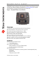
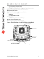
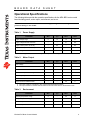
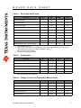
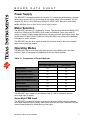
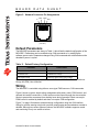
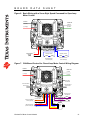
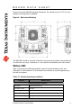
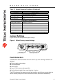
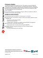
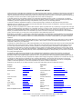
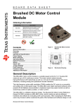
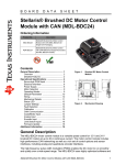
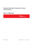
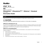
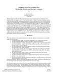
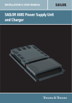
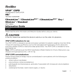
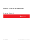
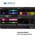
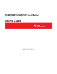
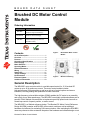
B O A R D D A T A S H E E T Brushed DC Motor Control Module Ordering Information Product No. Description MDL-BDC Stellaris® Brushed DC Motor Control Module for Single-Unit Packaging MDL-BDC-B Stellaris® Brushed DC Motor Control Module for Volume Packaging RDK-BDC Stellaris® Brushed DC Motor Control Reference Design Kit (includes the MDL-BDC module) Contents General Description ....................................... 1 Overview ......................................................... 2 Features .......................................................... 2 Operational Specifications ........................... 4 Power Supply ................................................. 7 Motor Selection .............................................. 7 Operating Modes ........................................... 7 Default Parameters ........................................ 9 Wiring .............................................................. 9 Status LED .................................................... 11 Jumper Settings ........................................... 12 Fault Detection ............................................. 12 Firmware Update .......................................... 13 Additional Information ................................ 13 Figure 1. Brushed DC Motor Control Module Figure 2. Mechanical Drawing General Description The MDL-BDC motor control module is a variable speed control for 12 V brushed DC motors at up to 40 A continuous current. The motor control module includes high performance CAN networking as well as a rich set of control options and sensor interfaces, including analog and quadrature encoder interfaces. The high-frequency pulse width modulator (PWM) enables the DC motor to run smoothly and quietly over a wide speed range. The MDL-BDC uses highly optimized software and a powerful 32-bit Stellaris microcontroller to implement open-loop speed control as well as closed-loop control of speed, position, or motor current. The MDL-BDC is a Stellaris reference design. The Brushed DC Motor Control Reference Design Kit (RDK) contains an MDL-BDC motor control module as well as additional hardware and software for evaluating CAN communication. After evaluating the RDK-BDC, users may choose to either customize the parts of the hardware and software design or use Brushed DC Motor Control Module 1 B O A R D D A T A S H E E T the MDL-BDC without modification. See the Brushed DC Motor Control Reference Design Kit (RDK) User's Manual (available for download from www.ti.com/stellaris) for complete technical details on using and customizing the motor control board. Figure 3. Brushed DC Motor Control Module Overview The MDL-BDC motor control board provides the following features: Controls brushed 12 V DC motors up to 40 A continuous Controller Area Network (CAN) interface at 1 Mbit/s Industry-standard servo (PWM) speed input interface Limit switch, encoder, and analog inputs Fully enclosed module includes cooling fan Flexible configuration options with simple source file modification Easy to customize—full source code and design files available Factory source code compiles to less than 16 KB Features Quiet control of brushed DC motors – 15 kHz PWM frequency Two options for Speed control – Industry-standard R-C servo type (PWM) interface – Controller Area Network (CAN) interface CAN communication – Multicast shared serial bus for connecting systems in electromagnetically noisy environments – 1M bits/s bit rate – CAN protocol version 2.0 A/B Brushed DC Motor Control Module 2 B O A R D D A T A S H E E T – Full configurability of module options – Real-time monitoring of current, voltage, speed, and other parameters Status LED indicates Run, Direction, and Fault conditions Motor brake/coast selector Limit switch inputs for forward and reverse directions Quadrature encoder input (QEI) – Index input – 5 V supply output to encoder Analog input – Accepts 10 kΩ potentiometer or 0-3 V input Screw terminals for all power wiring Headers (0.1 inch pitch) for all control signals Figure 4. Detailed Drawing of the MDL-BDC Motor Control Module Internal cooling fan Motor terminals Ventilation slots CAN interface Servo-type speed control input Coast/Brake select Wire retention hooks Brushed DC Motor Control Module Analog potentiometer input 3 B O A R D D A T A S H E E T Operational Specifications The following tables provide the operation specifications for the MDL-BDC motor control board including power, motor output, environment, and so on. WARNING – Do not exceed the absolute maximum supply voltage of 15 Vdc. Doing so will cause permanent damage to the module. Table 1. Power Supply Parameter Min Typ Max Units Supply voltage range 6 12 13 Vdc Supply voltage absolute maximum – – 15a Vdc Supply current (motor off, fan off) – 90 – mA Supply current (motor off, fan on) – 156 – mA Under-voltage detect threshold – 6 – Vdc a. Exceeding this limit, even momentarily, will cause permanent damage. Table 2. Motor Output Parameter Min Typ Max Units Motor voltagea 0 – 12 V Motor current - continuous – – 40 A Motor current – for 2 seconds – – 60 A Motor current – peak at starting – – 100 A PWM frequency – 15.625 – kHz PWM resolution – 0.1 – % Output current for resistive loadsb – – 30 A a. The motor voltage is controlled by using a pulse-width modulated waveform. b. The output current for resistive loads is continuous and the value shown is the maximum value. Table 3. Environment Parameter Min Typ Max Units 0 – 50 °C -25 – 85 °C Fan on temperature – 42 – °C Fan off temperature – 38 – °C Operating temperature range Storage temperature range Brushed DC Motor Control Module 4 B O A R D Table 4. D A T A S H E E T Servo-Style Speed Input Parameter Min Typ Minimum pulse widtha,b – 0.67 Neutral pulse widthb – 1.5 – ms Maximum pulse widthb,c – 2.33 – ms 5.0125 – 29.985 ms 0.5 – 2.50625 ms Duty cycle range – – 50% % Digital high-level input current 2 5 25 mA Digital low-level input current – – 0.3 mA Watchdog time-out – 100 – ms Voltage isolation (servo+/- to other signals)d – – 40 V Servo signal period Valid pulse width range Max Units ms a. Sets full-speed in reverse. b. These are the default values. Pulse-width range can be calibrated for different values. See the servo PWM calibration procedure, “Servo-Style PWM Input” on page 7. c. Sets full-speed in forward direction. d. The servo input is optically isolated. Table 5. Analog Input Parameter Min Typ Max Units Analog input voltage 0 – 3 V Potentiometer value – 10 – kΩ 2.9 3.0 3.1 V Measurement resolution – 10-bit – bits Measurement rate – 15.625 – kHz Potentiometer reference voltage (+ pin)a a. With 10 kΩ potentiometer connected. Table 6. Voltage, Current, and Temperature Measurement Parameter Min Typ Max Units Temperature measurement accuracy – +/-6 – °C Supply voltage measurement accuracy – +/- 0.3 – V Motor current measurement accuracy – +/- 1 – A Measurement resolution – 10-bit – bits Measurement rate – 15.625 – kHz Brushed DC Motor Control Module 5 B O A R D Table 7. D A T A S H E E T Brake/Coast Input Parameter Min Typ Max Units Digital low-level input voltagea -0.3 – 1.3 V Digital high-level input voltageb 2.0 3.3 5.0 V Digital input pull-down resistor – 200 – kΩ Response time – 64 – us a. Selects Brake mode. b. Selects Coast mode. Table 8. Quadrature Encoder Input (QEI) Parameter Min Typ Max Units Digital low-level input voltagea -0.3 – 1.3 V Digital high-level input voltagea 2.0 3.3 5.0 V – 10 – kΩ Encoder rateb DC – 1 M Encoder supply voltage 4.90 5.0 5.10 V Encoder supply current – – 20 mA Min Typ Max Units 0.0133a 1 1 Mbps – 120 – Ω -27 – 40 V Watchdog time-out – 100 – ms Number of modules per networkc 1 – 63 # Digital input pull-up resistor a. Applies to A, B, and Index inputs. b. Measured in transitions per second. Table 9. CAN Interface Parameter Bit rate Recommended bus terminationb Absolute maximum CANH, CANL voltage a. Limited by fail-safe CAN transceiver SN65HVD1050. b. Two terminations per network. c. Must be a valid ID range. Brushed DC Motor Control Module 6 B O A R D D A T A S H E E T Power Supply The MDL-BDC is designed primarily for use with 12 V sealed lead-acid batteries, although other power sources can be used as long as the voltage range is not exceeded. See the Brushed DC Motor Control Reference Design Kit (RDK) User’s Manual for more detail. NOTE: MDL-BDC does not have reverse polarity input protection. Motor Selection The MDL-BDC operates 12 V brushed DC motors. Typical motors include the BI802-001A model from CIM and the RS-555PH-S255 model from Mabuchi. Some very small DC motors or motors in lightly loaded applications may have a limited useful speed range. See the Brushed DC Motor Control Reference Design Kit (RDK) User’s Manual for additional information on motor selection. The MDL-BDC can also drive resistive loads with some de-rating to allow for increased ripple current inside the module. Operating Modes The MDL-BDC can be controlled using either the servo-style PWM input or the CAN interface. Table 10 compares the capabilities of the two control methods. Table 10. Comparison of Control Methods Control Method Servo-Style PWM Input CAN Interface Speed Control Yes Yes Analog Position Control No Yes Encoder Position Control No Yes Configurable Parameters No Yes Voltage, Current Measurement No Yes Limit Switches Yes Yes Coast/Brake Feature Yes Yes Firmware Update No Yes The MDL-BDC does support the simultaneous use of CAN for monitoring and the servo-style input for speed. Servo-Style PWM Input The MDL-BDC incorporates support for speed and direction control using the standard servo-style interface found on many radio-control receivers and robot controllers. See the electrical specifications for default timing of this signal. Brushed DC Motor Control Module 7 B O A R D D A T A S H E E T To accommodate variation in the timing of the supplied signal, the MDL-BDC has a calibrate feature that sets new values for full-forward, full-reverse, and points in between. Follow these steps to initiate calibration: 1. Hold down the user switch for five seconds (see Figure 4 on page 3). 2. Set the controller to send a full-forward signal. 3. Set the controller to send a full-reverse signal. 4. Set the controller to send a neutral signal. 5. Release the user switch. The MDL-BDC samples these signals and centers the speed range and neutral position between these limits. NOTE: See the Brushed DC Motor Control Reference Design Kit (RDK) User’s Manual for additional calibration information. CAN Communication The Controller Area Network (CAN) provides a powerful interface for controlling one or more MDL-BDC modules. The MDL-BDC has two RJ11/RJ14 6P-4C sockets (more specifically, RJ16 sockets) for daisy-chaining modules using standard cables. Each end of the CAN network must be terminated properly. Each MDL-BDC module on the CAN bus is accessed using an assigned ID number. The ID number defaults to 1, but can be changed by sending a CAN assign ID command to the bus. The LED flashes green when the assign ID command is received and then flashes yellow when the button is pressed (with the number of yellow flashes corresponding to the ID number). Pressing the user switch on the MDL-BDC informs that particular module to accept the previously specified code. See the RDK-BDC User’s Manual on the RDK CD for instructions on how to set an ID using an EK-LM3S2965 evaluation board. The CAN protocol used by the MDL-BDC includes the following capabilities: Firmware update over CAN Read supply voltage, motor voltage, temperature, and current Set motor voltage or target position Set control mode to speed or position See the MDL-BDC CAN Communication API Specification for complete details. The RDK includes a CAN board with an example application that demonstrates CAN control. CAN Connector Pin Assignments The pin assignments for the RJ11 6P-4C connectors are defined in CAN in Automation (CiA DS102). Figure 5 on page 9 shows the network connector pin assignments. Brushed DC Motor Control Module 8 B O A R D D A T A S H E E T Figure 5. Network Connector Pin Assignments CANL CANH V+ GND 1 6 CAN Socket Viewed from Top (Tab down) Default Parameters The MDL-BDC parameters are shown in Table 11 which lists the default configuration of the MDL-BDC. Parameters can be modified using CAN commands or by modifying the software source code. Parameters changed using CAN commands are volatile and must be reloaded if power is cycled. Table 11. Default Factory Configuration Parameter Default Value Acceleration rate Instantaneous change Deceleration rate Instantaneous change Motor Control mode Open-loop speed control using voltage For additional information on parameters, see the Brushed DC Motor Control Reference Design Kit (RDK) User’s Manual. Wiring The MDL-BDC is controlled using either a servo-type PWM source or CAN commands. Figure 6 shows a typical, simple wiring arrangement with power, motor, PWM control, and optional limit-switch connections. Control wires must be looped through the wire retention hooks to prevent the connectors from shaking loose during operation. Basic servo-style PWM control is enabled by default and does not require CAN configuration. Figure 7 on page 10 shows an advanced wiring configuration using the CAN interface. Wiring for position sensing using both a position potentiometer and a quadrature encoder is detailed. Although two sensor types are shown, the MDL-BDC software supports control and monitoring of only one sensor at a time. Brushed DC Motor Control Module 9 B O A R D D A T A S H E E T Figure 6. Basic Wiring with a Servo-Style Speed Command for Open-loop Motor Control Power In Motor Out (-) Supply (-) Motor (+) Supply (+) Motor (+) Digital Speed Signal (PWM) Normally -closed Normally -closed Forward Direction Limit Switch(es ) Reverse Direction Limit Switch(es) (-) Figure 7. CAN-Based Control for Closed-loop Motor Control Wiring Diagram Power In Motor Out (-) Supply / GND (-) Motor (+) Supply (+) Motor User switch sets CAN ID CAN cable to/from other devices CAN cable to/from other devices Normally-closed limit switches GND Reverse Limit H=Coast, L=Brake External coast/brake control (optional) Forward Limit GND GND +3V Reference 10kΩ Potentiometer position sensor (opt) Brushed DC Motor Control Module 0-3V signal GND GND Index signal B signal A signal +5V supply Encoder (opt) 10 B O A R D D A T A S H E E T Figure 8 shows the MDL-BDC physical dimensions. The module has two 0.175” (4.5 mm) diameter mounting holes as indicated. Figure 8. Mechanical Drawing The MDL-BDC should be mounted so that the vents in the top and sides of the module are not restricted in any way. A clearance of ½ inch should be maintained around the module. Status LED Table 12 lists all of the LED status and fault codes for Normal Operating, Fault, and Calibration or CAN conditions. Fault information is prioritized, so only the highest priority fault will be indicated. Table 12. Normal Operating Conditions LED State Module Status Normal Operating Conditions Solid Yellow Neutral (speed set to 0) Fast Flashing Green Forward Fast Flashing Red Reverse Solid Green Full-speed forward Solid Red Full-speed reverse Fault Conditions Brushed DC Motor Control Module 11 B O A R D D A T A S H E E T Table 12. Normal Operating Conditions (Continued) LED State Module Status Normal Operating Conditions Slow Flashing Yellow Loss of CAN or servo link Slow Flashing Red Fault Calibration or CAN Conditions Flashing Red and Green Calibration mode active Flashing Red and Yellow Calibration mode failure Flashing Green and Yellow Calibration mode success Slow Flashing Green CAN ID assignment mode Fast Flashing Yellow Current CAN ID (count flashes to determine ID) Flashing Yellow CAN ID invalid (that is, Set to 0) awaiting valid ID assignment Jumper Settings Figure 9 shows the factory-default jumper settings. Figure 9. Default Factory Jumper Settings Coast / Brake (default = brake) Jumpers hold the limit switch inputs closed Fault Detection The MDL-BDC detects and shuts down the motor if any of the following conditions are detected: Power supply under-voltage Over temperature Over current Loss of CAN or servo-style speed link Limit switch activated in the current direction of motion The LED indicates a fault state during the fault condition and for three seconds after the fault is cleared (except for the limit switch and link faults, which are instantaneous). Brushed DC Motor Control Module 12 Firmware Update The MDL-BDC firmware can be updated over CAN. The capability to update the MDL-BDC firmware can be added to most Host controllers by implementing the necessary CAN protocol. For users who are not developing a CAN host controller, an application that runs on the Stellaris® LM3S2965 Evaluation Board (EK-LM3S2965) is provided. This board is included in the RDK. The example application can be downloaded from www.ti.com/stellaris. See the Brushed DC Motor Control Reference Design Kit (RDK) User’s Manual for additional information on the firmware update procedure. Additional Information The following documents are available for download at www.ti.com/stellaris: Brushed DC Motor Control Reference Design Kit (RDK) User’s Manual, Publication number RDK-BDC-UM – Schematics and Bill-of-Materials (BOM) – Detailed functional description – Firmware update, configuration, and operation using the RDK-BDC test application Brushed DC Motor Control (RDK) Quickstart Guide – A step-by-step guide to using the reference design kit (RDK-BDC) RDK-BDC Firmware Development Package User’s Guide, Publication number SW-RDK-BDC-UG – Part of the StellarisWare® source code library Copyright © 2007–2010 Texas Instruments, Inc. All rights reserved. Stellaris and StellarisWare are registered trademarks of Texas Instruments. ARM and Thumb are registered trademarks, and Cortex is a trademark of ARM Limited. Other names and brands may be claimed as the property of others. BD-BDC-DS-02 February 9, 2010 IMPORTANT NOTICE Texas Instruments Incorporated and its subsidiaries (TI) reserve the right to make corrections, modifications, enhancements, improvements, and other changes to its products and services at any time and to discontinue any product or service without notice. Customers should obtain the latest relevant information before placing orders and should verify that such information is current and complete. All products are sold subject to TI’s terms and conditions of sale supplied at the time of order acknowledgment. TI warrants performance of its hardware products to the specifications applicable at the time of sale in accordance with TI’s standard warranty. Testing and other quality control techniques are used to the extent TI deems necessary to support this warranty. Except where mandated by government requirements, testing of all parameters of each product is not necessarily performed. TI assumes no liability for applications assistance or customer product design. Customers are responsible for their products and applications using TI components. To minimize the risks associated with customer products and applications, customers should provide adequate design and operating safeguards. TI does not warrant or represent that any license, either express or implied, is granted under any TI patent right, copyright, mask work right, or other TI intellectual property right relating to any combination, machine, or process in which TI products or services are used. Information published by TI regarding third-party products or services does not constitute a license from TI to use such products or services or a warranty or endorsement thereof. Use of such information may require a license from a third party under the patents or other intellectual property of the third party, or a license from TI under the patents or other intellectual property of TI. Reproduction of TI information in TI data books or data sheets is permissible only if reproduction is without alteration and is accompanied by all associated warranties, conditions, limitations, and notices. Reproduction of this information with alteration is an unfair and deceptive business practice. TI is not responsible or liable for such altered documentation. Information of third parties may be subject to additional restrictions. Resale of TI products or services with statements different from or beyond the parameters stated by TI for that product or service voids all express and any implied warranties for the associated TI product or service and is an unfair and deceptive business practice. TI is not responsible or liable for any such statements. TI products are not authorized for use in safety-critical applications (such as life support) where a failure of the TI product would reasonably be expected to cause severe personal injury or death, unless officers of the parties have executed an agreement specifically governing such use. Buyers represent that they have all necessary expertise in the safety and regulatory ramifications of their applications, and acknowledge and agree that they are solely responsible for all legal, regulatory and safety-related requirements concerning their products and any use of TI products in such safety-critical applications, notwithstanding any applications-related information or support that may be provided by TI. Further, Buyers must fully indemnify TI and its representatives against any damages arising out of the use of TI products in such safety-critical applications. TI products are neither designed nor intended for use in military/aerospace applications or environments unless the TI products are specifically designated by TI as military-grade or "enhanced plastic." Only products designated by TI as military-grade meet military specifications. Buyers acknowledge and agree that any such use of TI products which TI has not designated as military-grade is solely at the Buyer's risk, and that they are solely responsible for compliance with all legal and regulatory requirements in connection with such use. TI products are neither designed nor intended for use in automotive applications or environments unless the specific TI products are designated by TI as compliant with ISO/TS 16949 requirements. Buyers acknowledge and agree that, if they use any non-designated products in automotive applications, TI will not be responsible for any failure to meet such requirements. Following are URLs where you can obtain information on other Texas Instruments products and application solutions: Products Applications Amplifiers amplifier.ti.com Audio www.ti.com/audio Data Converters dataconverter.ti.com Automotive www.ti.com/automotive DLP® Products www.dlp.com Communications and Telecom www.ti.com/communications DSP dsp.ti.com Computers and Peripherals www.ti.com/computers Clocks and Timers www.ti.com/clocks Consumer Electronics www.ti.com/consumer-apps Interface interface.ti.com Energy www.ti.com/energy Logic logic.ti.com Industrial www.ti.com/industrial Power Mgmt power.ti.com Medical www.ti.com/medical Microcontrollers microcontroller.ti.com Security www.ti.com/security RFID www.ti-rfid.com Space, Avionics & Defense www.ti.com/space-avionics-defense RF/IF and ZigBee® Solutions www.ti.com/lprf Video and Imaging www.ti.com/video Wireless www.ti.com/wireless-apps Mailing Address: Texas Instruments, Post Office Box 655303, Dallas, Texas 75265 Copyright © 2010, Texas Instruments Incorporated