1
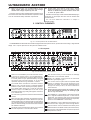
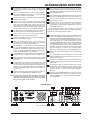
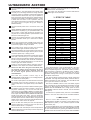
Version 1.2 January 2003 ENGLISH ACX1000 ULTRACOUSTIC Users manual ULTRACOUSTIC ACX1000 IMPORTANT SAFETY INSTRUCTIONS DETAILED SAFETY INSTRUCTIONS: 1) Read these instructions. 2) Keep these instructions. 3) Heed all warnings. 4) Follow all instructions. CAUTION: WARNING: To reduce the risk of electric shock, do not remove the top cover (or the rear section). No user serviceable parts inside; refer servicing to qualified personnel. To reduce the risk of fire or electric shock, do not expose this appliance to rain and moisture. This symbol, wherever it appears, alerts you to the presence of uninsulated dangerous voltage inside the enclosurevoltage that may be sufficient to constitute a risk of shock. This symbol, wherever it appears, alerts you to important operating and maintenance instructions in the accompanying literature. Please read the manual. 5) Do not use this device near water. 6) Clean only with a dry cloth. 7) Do not block any ventilation openings. Install in accordance with the manufacturers instructions. 8) Do not install near any heat sources such as radiators, heat registers, stoves, or other apparatus (including amplifiers) that produce heat. 9) Do not defeat the safety purpose of the polarized or grounding-type plug. A polarized plug has two blades with one wider than the other. A grounding type plug has two blades and a third grounding prong. The wide blade or the third prong are provided for your safety. If the provided plug does not fit into your outlet, consult an electrician for replacement of the obsolete outlet. 10) Protect the power cord from being walked on or pinched particularly at plugs, extension cords, and the point at which they exit the unit. 11) Only use attachments/accessories specified by the manufacturer. 12) Use only with the cart, stand, tripod, bracket, or table specified by the manufacturer, or sold with the device. When a cart is used, use caution when moving the cart/ device combination to avoid injury from trembling over it. 13) Unplug this device during lightning storms or when not used for long periods of time. 14) Refer all servicing to qualified service personnel. Servicing is required when the unit has been damaged in any way, such as power supply cord or plug is damaged, liquid has been spilled or objects have fallen into the device, the unit has been exposed to rain or moisture, does not operate normally, or has been dropped. 2 ULTRACOUSTIC ACX1000 ULTRACOUSTIC Ultra-flexible 2 x 60-Watt, 2-channel stereo acoustic instrument amplifier with digital multi-effects processor ACX1000 s Powerful 2 x 60-Watt RMS amplifier with tube emulator specifically designed for acoustic instruments and vocals s Dedicated tube emulator in both channels adds warmth and presence to instruments and vocals s Two independent channels with separate volume controls, dedicated EQs and two feedback filters each s Instrument channel produces warm and transparent sound for pickup-equipped instruments and features additional ATTACK and EFFECT controls plus two tunable notch filters for feedback suppression s Microphone/line channel provides microphone inputs with phantom power for both dynamic and condenser microphones, ENHANCER control, EFFECT control and two tunable notch filters optimized for suppressing microphone feedback s Active 3-band EQ per channel s 24-bit stereo multi-effects processor with high-resolution 24-bit A/D & D/A converters s 23 algorithms, specifically developed for the ULTRACOUSTIC, producing authentic effects such as Reverb, Delay, Rotary Speaker, Chorus, Flanger, Stereo Panning, Tremolo and various effects combinations for instrument and microphone/line channels s 99 programs stored in 4 presets that can be recalled via footswitch s Parallel TUNER output for tuner connection s Adjustable stereo aux input on phone jacks for adding line signals (e.g. CD player, drum computer etc.) with AUX LEVEL control and MUTE switch s Stereo tape input/output s Separate insert option for external effects devices (e.g. compressor, octaver etc.) for both channels as well as master section s Includes footswitch FS114 for effects switching s MIDI effects selection via program change commands s Master volume control with switchable phase correction s High-quality components and exceptionally rugged construction for long life and durability s Generously dimensioned power supply ensures excellent pulse response s Manufactured under ISO9000 certified management system 3 ULTRACOUSTIC ACX1000 FOREWORD Dear Customer, welcome to the team of BEHRINGER users and thank you very much for expressing your confidence in us by purchasing the ACX1000. Writing this foreword for you gives me great pleasure, because it represents the culmination of many months of hard work delivered by our engineering team to achieve a very ambitious goal: To present you with an excellent 2-channel acoustic guitar amplifier which features authentic sound quality and an integrated digital multi-effects device, not to forget the professional design. The task of designing our new ACX1000 certainly meant a great deal of responsibility which we assumed by focusing on you, the discerning user and musician. Meeting your expectations also meant a lot of work and night shifts. But it was fun, too. Developing a product usually brings a lot of people together, and what a great feeling it is when all who participated in such a project can be proud of what theyve achieved. TABLE OF CONTENTS 1. INTRODUCTION ......................................................... 5 1.1 The design concept ...................................................... 5 1.1.1 Tube emulator ..................................................... 5 1.2 Before you begin .......................................................... 5 2. CONTROL ELEMENTS ............................................... 6 2.1 Front panel .................................................................... 6 2.2 Rear panel ..................................................................... 7 3. EFFECTS TABLE ......................................................... 8 3.1 MIDI control .................................................................... 8 4. INSTALLATION ........................................................... 9 4.1 4.2 4.3 4.4 Mains connection .......................................................... 9 Audio connections ........................................................ 9 MIDI connection ............................................................. 9 MIDI implementation ..................................................... 10 5. SPECIFICATIONS ..................................................... 10 6. WARRANTY .............................................................. 11 It is our philosophy to share our enjoyment with you, because you are the most important member of the BEHRINGER team. With your highly competent suggestions for new products youve made a significant contribution to shaping our company and making it successful. In return, we guarantee you uncompromising quality as well as excellent technical and audio properties at an extremely reasonable price. All of this will enable you to give free rein to your creativity without being hampered by budget constraints. We are often asked how we manage to produce such high-quality devices at such unbelievably low prices. The answer is quite simple: its you, our customers! Many satisfied customers mean large sales volumes enabling us to get better purchasing terms for components, etc. Isnt it only fair to pass this benefit on to you? Because we know that your success is our success too! I would like to thank all of you who have made the ACX1000 possible. You have all made your own personal contributions, from the developers to the many other employees at this company, and to you, the BEHRINGER user. My friends, its been worth the effort! Thank you very much, Uli Behringer 4 + WARNING! It should be pointed out, that extreme output volumes may damage your ears and/or your headphones. Turn down all LEVEL controls before you switch on the unit. Always pay attention to an appropriate volume. ULTRACOUSTIC ACX1000 1. INTRODUCTION s Sophisticated analog technology with a feel factor only analog technology can provide. Thank you very much for expressing your confidence in BEHRINGER products by purchasing the ULTRACOUSTIC ACX1000. With the ULTRACOUSTIC, you have acquired a stateof-the-art 2-channel amplifier that can be operated easily and quickly, and enables you to create out-of-the-ordinary sounds for a variety of applications. s Latest DSP technology to give you a broad range of modern studio-compatible effect sounds. s Rugged and solid construction which even withstands the roughest handling. s Intuitive operation, so that you can focus your mind on what is most important to you: your music! When developing the ACX1000, our top objective was to reproduce the pure and detail-rich sound of acoustic instruments and to help you work out the characteristic properties of your instrument. For this reason the instrument channel includes a number of controls tailored specifically to meet the requirements of acoustic instruments. Whats more, your ULTRACOUSTIC has a second microphone/instrument channel with about the same control elements plus an enhancer circuit that gives, for example, vocals increased presence and liveliness. A very special feature is the ULTRACOUSTICs digital multi-effects processor with its wealth of studio-compatible effects. The tube emulator gives audio signals in both channels unmistakable tube quality and adds that much sought-after effect of warmth and transparency. When working in the studio or on stage, you will find the numerous connection options on your ACX1000 very helpful. And despite its extremely flexible design, your ULTRACOUSTIC can be operated easily and intuitively. BEHRINGER is an audio engineering company that has been successfully developing products for studio and live applications for many years now. Our range of products includes microphones and a variety of 19" devices (compressors, enhancers, gates, tube processors, headphone amps, digital effects devices, DI boxes etc.) as well as various monitoring and P.A. speakers plus professional live and recording consoles. The name of BEHRINGER stands for no-compromise quality, fullyfeatured products and exemplary serviceeven years after purchaseas well as sensationally low prices, which allow any ambitious music lover to make their musical dreams come true. We also set great store by flexibility, which has become a particularly important factor in the music business over the past few years. Modern guitarists and musicians need to offer a broad range of sounds, but should still be able to play in different kinds of applications at short notice: home recording, studio, live concerts. For this reason, it has always been our prime concern to give you a maximum of functions that can still be operated intuitively and quicklyno matter what kind of style you play. As technology advances, youve got to keep track of latest technological breakthroughs to avoid falling by the wayside. We too have continuously improved the ULTRACOUSTIC and included many of your valuable suggestions. We have spared neither expense nor effort to test different types of circuitry and speakers until the results have given us complete satisfaction. After all, we really want to give you fully designed and developed products that meet your expectations in every respect. The ULTRACOUSTIC shall be a useful tool for years to come, which is why weve equipped the effects modules of our entire guitar amplifier series with EPROMS that can be updated. In this way, we can keep working on new algorithms and considering your ideas and suggestions. The resulting software updates will be made available for free on the Internet, so as to ensure that your amp will never be outdated. Weve packed our entire experience into this latest-generation acoustic guitar amp. Many people contributed to this project of intense development: studio musicians, collectors of vintage guitar amps, music and guitar lovers alike. All of them helped us develop an amplifier that gives you the best of all worlds: + This manual first describes the terminology used, so that you can fully understand the ULTRACOUSTIC and its functions. Please read the manual carefully and keep it for future reference. 1.1 The design concept The philosophy behind BEHRINGER products guarantees a no-compromise circuit design and employs the best choice of components. The operational amplifiers used in the ULTRACOUSTIC are exceptional: they boast extreme linearity and very low distortion characteristics. To complement this design, the choice of components include low-tolerance resistors and capacitors, high-quality potentiometers and several other stringently selected elements. The ULTRACOUSTIC uses SMD technology (Surface Mounted Device). These subminiature components adapted from aerospace technology allow for an extreme packing density to further improve the overall reliability. The super-robust steel enclosure of your ULTRACOUSTIC, with its generously proportioned high-capacity power supply and temperature-controlled active fan, makes sure that your ACX1000 keeps on working even when the going gets tough. The cabinet is made of high-grade, non-polluting E1-MDF boards, which are grooved, multi-glued and free of formaldehyde. 1.1.1 Tube emulator A special FET circuit in your ULTRACOUSTIC emulates the positive characteristics of a tube exciter, producing additional harmonics and a subtle compression effect which gives your guitar sounds the power to make themselves heard and adds sustain and definition. Acoustic guitars, in particular, with their wide dynamic range, need to produce a homogeneous sound image in all registers. The FET circuit makes sure that even the high registers have sufficient sustain and wont get drowned. While the WARMTH control allows you to add the tube sound effect as desired. By using solid-state components we succeeded in eliminating tube-specific interference noise to a great extent; the actual tube effect is thus achieved without additional noise or hum. 1.2 Before you begin Your BEHRINGER ULTRACOUSTIC was carefully packed in the factory and the packaging is designed to protect the unit from rough handling. Nevertheless, we recommend that you carefully examine the packaging and its contents for any signs of physical damage, which may have occurred during transit. + If the unit is damaged, please do not return it to BEHRINGER, but notify your dealer and the shipping company immediately, otherwise claims for damage or replacement may not be granted. Shipping claims must be made by the consignee. Be sure that there is enough space around the unit for cooling and please do not place the ULTRACOUSTIC on high temperature devices such as radiators etc. to avoid overheating. 1. INTRODUCTION 5 ULTRACOUSTIC ACX1000 + Before you connect your ULTRACOUSTIC to the mains, please make sure that your local voltage matches the voltage required by the unit! The mains connection of the ULTRACOUSTIC is made by using the enclosed mains cable and a standard IEC receptacle. It meets all of the international safety certification requirements. + Please make sure that all units have a proper ground connection. For your own safety, never remove or disable the ground conductor of the unit or of the AC power cable. The MIDI connection (IN) is made with standardized DIN plug-in connectors. An optocoupler has been used for isolated data communications. You will find additional information in chapter 3 INSTALLATION. 2. CONTROL ELEMENTS Fig. 2.1: The front panel of the ULTRACOUSTIC Your BEHRINGER ULTRACOUSTIC ACX1000 is equipped with 20 front panel controls, 9 push-buttons and a 2-digit, 7-segment LED display. Two 1/4" phone jacks and one XLR jack are available as well. 2.1 Front panel Fig. 2.2: The front panel control elements Use the 1/4" INSTRUMENT jack on the instrument channel to connect an acoustic guitar to your ULTRACOUSTIC. Please use a commercial 1/4" jack mono cable (no DIY (Do It Yourself), better ask your specialized dealer), with good mechanical and electrical shielding, so as to avoid unpleasant surprises during rehearsals or concerts. With the MID control you can boost/cut the midrange frequencies on the instrument channel. Finally, the TREBLE control governs the instrument channels high frequency gain. The PHASE switch reverses the instrument channels phase by 180°. Use this function to eliminate feedback problems or phase errors caused by dual pickup systems. The TUNER switch allows you to mute the instrument channels output. The TUNER jack on the rear of your ACX1000 provides a copy of the guitar signal for connection to an external tuner. The GAIN control governs the volume level of the instrument channel. When the input signal overdrives the instrument channel, the CLIP LED signals this condition. Reduce the input gain with the GAIN control, until the CLIP LED just stops lighting up. Occasional flashing of the CLIP LED, caused by signal peaks, is harmless though, because the instrument channel has sufficient headroom. The BASS control in the EQ section allows you to boost/cut the bass frequencies on the instrument channel. 6 + The ATTACK control is quite useful to emphasize attack sounds. For example, when you pick the strings of your guitar with your fingers, try turning the ATTACK control to the right. The more you do so, the more accented the sound becomes. Please note that with all three EQ controls set fully to the left (instrument channel), the resulting signal will be very low-volume. The FEEDBACK 1 control adjusts a notch filter that allows you to suppress feedback frequencies or other forms of interference. The frequency range is from 65 Hz through 400 Hz. To detect and suppress interference frequencies, please turn the FEEDBACK 1 control slowly. The FEEDBACK 2 control determines the frequency of a second notch filter, ranging from 150 Hz through 900 Hz. Use the EFFECT control to determine the intensity of the effect selected on the effects module (instrument channel). The MIC jack is the balanced XLR microphone input of the microphone/line channel. 2. CONTROL ELEMENTS ULTRACOUSTIC ACX1000 The balanced LINE/INST. jack of the microphone/line channel can be used for line-level signals, e.g. keyboards, samplers etc. The +48 V switch activates the phantom power supply for the XLR microphone input, providing the operating voltage required for condenser microphones. Use the GAIN control to determine the volume level of the microphone/line channel. When the input signal overdrives the microphone/line channel, the CLIP LED signals this condition. Reduce the input gain with the GAIN control, until the CLIP LED just stops lighting up. Occasional flashing of the CLIP LED, caused by signal peaks, is harmless though, because the microphone/line channel, too, has sufficient headroom. The BASS control in the EQ section allows you to boost/cut the bass frequencies on the microphone/line channel. With the MID control you can boost/cut the midrange frequencies on the microphone/line channel. Finally, the TREBLE control governs the microphone/line channels high frequency gain. With the ENHANCER control you can add treble frequencies to the microphone/line signal, thus improving the audio signals power and transparency. The FEEDBACK 1 control adjusts a notch filter that allows you to suppress feedback frequencies or other forms of interference. The frequency range is from 650 Hz through 4 kHz. To detect and suppress interference frequencies, please turn the FEEDBACK 1 control slowly. The FEEDBACK 2 control determines the frequency of a second notch filter, ranging from 1.5 kHz through 9.5 kHz. Use the EFFECT control to determine the intensity of the effect selected on the effects module (microphone/line channel). The WARMTH control adjusts the ULTRACOUSTICs tube emulator circuit. The more you turn this control to the right, the more upper harmonics are added to the signals on the instrument or microphone/line channels, which results in a sound of unobtrusive brilliance with improved power and transparency. Use this CONTROL INDICATOR to assess the amount of upper harmonics added with the WARMTH control. + To achieve the maximum tube emulation effect, both channels should be set to correct levels. The CLIP LED should be flashing with signal peaks only. Make sure it never lights up all the time. The PHASE switch reverses the phase of the mix signal by 180°. Use this switch to eliminate feedback problems. The MASTER control determines the overall volume level of your ULTRACOUSTIC. The ULTRACOUSTIC features a limiter circuit in the master section. The LIM LED lights up as soon as the limiter is on. The AUX input on the rear of your ACX1000 can be muted with the MUTE switch. The AUX LEVEL control in the master section adjusts the volume level of the AUX signal (e.g. drum computer, playback) fed in via the AUX IN or TAPE IN jacks on the rear of the ULTRACOUSTIC. Your ACX1000 features an on-board effects module that produces 23 different types of effects comprising 99 effect variations plus associated program numbers. Use the four PRESET buttons to assign an effects program to one of the PRESET buttons and recall it from there. To save a preset selected with the PROGRAM control, simply press one of the four PRESET buttons for about 2 seconds, until its LED lights up. To recall a stored preset, press the corresponding PRESET button. The mix of signals adjusted with the EFFECT control will of course be stored as well. To adjust the MIDI receive channel, press PRESET buttons #3 and #4. Then, select a MIDI channel with the PROGRAM control (1 through 16, on = Omni, OF = inactive). Finally, quit the menu by pressing either one of the PRESET buttons. Select one of 99 effect programs with the PROGRAM control. The INSTRUMENT CLIP LED lights up as soon as the effects module starts distorting. Reduce the input gain on the instrument channel. The MIC CLIP LED lights up as soon as the effects module starts distorting. Reduce the input gain on the microphone/ line channel. The DISPLAY reads the program number of the currently active preset. Use the table printed on the effects module to locate the various groups of effects and associated program numbers. -- means that the effects module is disabled. When you press the POWER switch on the rear of the unit, the POWER LED lights up. Be sure to properly connect your ULTRACOUSTIC to the mains before (see chapter 3 INSTALLATION). 2.2 Rear panel Fig. 2.3: The rear panel connectors 2. CONTROL ELEMENTS 7 ULTRACOUSTIC ACX1000 Use the POWER switch to put the ULTRACOUSTIC into operation. The instrument channel also features an insert path. This is the INSTR. INS. SEND jack. FUSE HOLDER / VOLTAGE SELECTOR. Please make sure that your local voltage matches the voltage indicated on the unit, before you attempt to connect and operate the ULTRACOUSTIC. Blown fuses may only be replaced by fuses of the same type and rating. Some models allow for inserting the fuse holder in two different positions, in order to switch over from 230 V to 120 V operation, and vice versa. Please note that for 120 V operation outside Europe, you need a fuse of a higher rating (see chapter 3 INSTALLATION). The INSTR. INS. RETURN jack is used to feed back the effect signal to the ACX1000. Use the enclosed power cord to connect the unit to the mains. SERIAL NUMBER. Please take the time to have the warranty card filled out completely by your specialized dealer, and return it within 14 days after the date of purchase. You may also use our online registration option available on the Internet at www.behringer.com. Connect the enclosed footswitch to the FOOTSWITCH jack. The footswitch allows you to recall the four effects presets. MIDI IN. This connector gives you MIDI remote control over your ULTRACOUSTIC. You can change effects programs by means of program change commands. The TUNER output always provides the instrument channels audio signal to feed an external tuner. The balanced DIRECT OUT jack provides a line-level copy of the instrument channels signal. Use this jack to connect an external power amp or mixing console. Your ULTRACOUSTIC also features a serial stereo master insert path, which allows you to insert external effects devices. These are the MASTER INSERT SEND jacks for the left and right channels, which should be connected to the inputs of the external effects device. You can also tap a stereo signal from these connectors. + These are the MASTER INSERT RETURN jacks for connection to the outputs of an external effects device. Please note that when using the serial effects path, the external effects device should not be set to 100% wet (100% effect signal); otherwise, there will be no direct signal portion fed back to the ULTRACOUSTIC. The TAPE OUT provides a stereo copy of the ULTRACOUSTICs audio signal, e.g. for recording purposes. The TAPE OUT is on RCA jacks. The TAPE IN jacks perform the same function as the AUX IN. However, due to the RCA connectors you can also connect a tape deck or hi-fi system directly to the TAPE IN jacks. The AUX IN allows you to feed in additional stereo signals, for example, to play with a drum computer or some sort of playback. Additionally, you can use the AUX IN in combination with the INSERT SEND as a parallel effect path: connect the INSERT SEND to the input and the AUX IN to the output of the effects device (INSERT RETURN jacks should not be used in this case!). Thus, the signal path inside the amplifier will not be interrupted and you can add the effect portion from the external device, using the AUX LEVEL control. Please note that the external effects device must be set to 100% wet for this purpose. This is the MIC INS. SEND jack of the microphone/line channels insert path. Connect this jack to the input of an external effects device or compressor. This is the MIC INS. RETURN jack of the microphone/line channels insert path. Connect this jack to the output of an external effects device. 8 3. EFFECTS TABLE Preset no. Effect Effect type -Bypass 01 - 03 Chorus + Delay + Reverb Parallel 04 - 06 Chorus + Room 1 Parallel 07 - 09 Chorus + Room 2 Parallel 10 - 13 Chorus + Hall Parallel 14 - 15 Flanger + Reverb Parallel 16 - 19 Delay + Room 1 Parallel 20 - 22 Delay + Room 2 Parallel 23 - 25 Delay + Hall Parallel 26 - 28 Delay + Chorus Parallel 29 - 35 Room Single 36 - 42 Hall Single 43 - 47 Plate Single 48 - 58 Delay Single 59 - 63 Multitap Delay Single 64 - 68 Chorus Single 69 - 70 Flanger Single 71 - 73 Rotary Speaker Single 74 - 76 Tremolo Single 77 - 78 Pan Single 79 - 81 Reverb / Reverb Dual 82 - 87 Slow Chorus / Reverb Dual 88 - 93 Fast Chorus / Reverb Dual 94 - 96 Delay / Reverb Dual 97 - 99 Rotary Speaker / Reverb Dual Tab. 3.1: The effect algorithms of the ULTRACOUSTIC A very special feature of your ULTRACOUSTIC is its built-in multi-effects processor that creates a variety of first-class, studio-compatible algorithms. This effects module provides a total of 99 preset, organized in 23 different groups of effects. Each group comprises a number of presets with varying parameter settings and covering a broad spectrum of effects and effects combinations. The range of effects provided consists of single, parallel and dual effects. The single and parallel effects provide an effect or effects combination for both channels. The dual effects allow you to give each channel its own effect. Use the four PRESET buttons to store one effects program each, including the mix ratio adjusted with the EFFECT controls (original vs. effect signal for both channels). To store a preset selected with the PROGRAM control, simply press one of the four PRESET buttons for about 2 seconds, until its associated LED lights up. To recall the four presets stored, press one of the PRESET buttons or one of the four buttons on the enclosed footswitch. 3.1 MIDI control With its built-in MIDI interface you can control the ULTRACOUSTIC via MIDI, for example, to select effects from a MIDI sequencer (studio), or from a master keyboard or MIDI footcontroller (live). Connect the MIDI IN jack of your ULTRACOUSTIC to the MIDI OUT jack of a MIDI footcontroller. Now, enable the MIDI functions on your ULTRACOUSTIC by pressing the PRESET buttons #3 and #4 for about two seconds: the two control LEDs of PRESET 3. EFFECTS TABLE ULTRACOUSTIC ACX1000 buttons #3 and #4 start flashing, the right decimal point in the display lights up. Select a MIDI channel with the PROGRAM control (1 through 16, on = Omni, OF = inactive) and quit the menu by pressing either one of the PRESET buttons. Omni mode means that your ULTRACOUSTIC receives and processes MIDI information on all MIDI channels. Of course, you should select the same channel both on your MIDI footcontroller and ACX1000 (see MIDI footcontroller users manual). You can select presets via MIDI using program change commands. When you send program change command #127, the effects module of your ACX1000 will be bypassed, i.e. you will hear no effect. As is usual with MIDI program change commands, program change #0 corresponds to program #1, and program change #1 to program #2, etc. (see table 4.1 in the appendix). The program change numbers 99 through 102 select the preset stored for the four PRESET buttons. After changeover the preset is activated immediately, i.e. it will not be affected by previously adjusted bypass settings. Fig. 4.2: 1/4" mono jack 4. INSTALLATION 4.1 Mains connection Please ensure that the ULTRACOUSTIC is set to the correct supply voltage before connecting the unit to the AC power system! Three triangular markings can be found on the fuse holder at the AC power connection socket. Two of these three triangles will be aligned with one another. The ULTRACOUSTIC is set to the operating voltage shown next to these markings and can be switched over by twisting the fuse holder by 180°. IMPORTANT: This does not apply to export models designed only for 120 V~! The mains connection of the ULTRACOUSTIC is made by using the enclosed mains cable and a standard IEC receptacle. It meets all of the international safety certification requirements. 4.2 Audio connections Except for the MIC and LINE/INST. inputs and the DIRECT OUT, the audio inputs and outputs of your BEHRINGER ULTRACOUSTIC are on unbalanced connectors. Please use commercially available RCA connectors for the TAPE inputs and outputs. + Please ensure that only qualified persons install and operate the ULTRACOUSTIC. During installation and operation the user must have sufficient electrical contact to earth. Electrostatic charges might affect the operation of the ULTRACOUSTIC! Fig. 4.3: 1/4" stereo jack connector 4.3 MIDI connection The MIDI standard (Musical Instruments Digital Interface) was developed in the early 80s to enable electronic musical instruments of different makes to communicate with each other. Over the years the range of MIDI applications has constantly expanded, and today it is completely normal to network entire recording studios using the MIDI standard. At the heart of this network we find a computer loaded with a sequencer software that controls not only the keyboards but also effects and other peripheral devices. In such a studio you could control your ULTRACOUSTIC in real time from a computer. In particular, when playing live gigs you can use a MIDI footcontroller to control both the effect parameters and channel/ effect changes on your ULTRACOUSTIC. The MIDI connector on the rear of your ULTRACOUSTIC is an internationally standardized 5-pin DIN jack. To connect your ULTRACOUSTIC to other MIDI equipment, you need a dedicated MIDI cable, which is commercially available in various lengths. However, you can solder your own cables using 2-conductor shielded cables (e.g. microphone cables) and two rugged 180° DIN plugs: pin 2 (center) = shield; pins 4 and 5 (right and left of pin 2) = internal conductor; pins 1 and 3 (the outer pins) are not used. MIDI cables should not exceed a length of 15 meters. + Make sure that pin 4 is connected to pin 4, and pin 5 to pin 5 on both plugs. MIDI IN: receives MIDI controller information. The receiving channel can be set with the buttons UP and DOWN. On = Omni, i.e. MIDI data are received and processed on all channels (see section 3.2). Fig. 4.1: XLR connections 4. INSTALLATION 9 ULTRACOUSTIC ACX1000 4.4 MIDI implementation 0,',,PSOHPHQWDWLRQ&KDUW 7UDQVPLWWHG 5HFRJQL]HG 5HPDUNV )XQFWLRQ Basic Channel Default Changed X X OFF, 1 - 16 OFF, 1 - 16 Mode Default Messages Altered X X X X X X X X X 1, 2 X X X X X X X X X X X X O (0 - 98) Note Number Velocity After Touch Pitch Bender True Voice Note ON Note OFF Keys Channels AUDIO OUTPUTS Direct out output Connector Type memorized Output impedance Max. output level Tape output Connector Type Output impedance Max. output level Progr. Change X POWER AMPLIFIER Power amp output X 127: Bypass 99 - 102: PRESET BUTTON 1-4 Type 5-pin-DIN-socket, MIDI IN DIGITAL PROCESSING Converters Sampling rate X X Type X X X X X X LOUDSPEAKER System Clock Real Time Commands X X X X Local ON/OFF Aux Messages All notes OFF Active Sense Reset X X X X X X X X Song Pos. Song Sel. Tune Type Impedance Power handling 24-bit sigma-delta, 64/128-times oversampling 46.875 kHz Mains voltages O = YES, X = NO Mode 1: OMNI ON Power consumption Fuse OMNI OFF Tab. 4.1: MIDI implementation Mains connection Dimensions (H x W x D) AUDIO INPUTS Microphon/line channel Microphone input Connector Type Input impedance Line input Connector Type Input impedance Aux/tape input Connector Type Input impedance 2 x 8" loudspeaker, special custom-made acoustic speaker; 1 x piezo tweeter 8 Ω (8" loudspeaker) max. 60 Watts (8" loudspeaker) USA/Canada 120 V~, 60 Hz Europe/U.K./Australia 230 V~, 50 Hz Japan 100 V~, 50 - 60 Hz general export model 120/230 V~, 50 - 60 Hz 42 Watts min./200 Watts max. 100 - 120 V~: T 5 A H 200 - 240 V~: T 2.5 A H standard IEC receptacle PHYSICAL 5. SPECIFICATIONS Instrument channel Connector Type Input impedance 2-digit numeric LED display POWER SUPPLY Notes 10 2 x 60 Watts RMS DISPLAY System Exclusive Mode 2: RCA unbalanced, low-impedance line-level output app. 100 Ω +20 dBu unbalanced MIDI INTERFACE Control System Common XLR balanced, low-impedance line-level output app. 200 Ω balanced 100 Ω unbalanced +24 dBu balanced 1/4" phone jack unbalanced, RF filtered input app. 10 MΩ Weight app. 17" (431.8 mm) x 23 2/3" (600.65 mm) x 10 3/5" (270 mm) / 12 3/10" (312.6 mm) app. 48.51 Ibs (22 kg) XLR balanced, RF filtered input app. 25 kΩ 1/4" TRS jack balanced, RF filtered input app. 40 kΩ balanced 20 kΩ unbalanced 1/4" phone jack/RCA unbalanced, RF filtered input app. 10 kΩ BEHRINGER is constantly striving to maintain the highest professional standards. As a result of these efforts, modifications may be made from time to time to existing products without prior notice. Specifications and appearance may differ from those listed or illustrated. 5. SPECIFICATIONS ULTRACOUSTIC ACX1000 6. WARRANTY § 1 WARRANTY CARD/ONLINE REGISTRATION To be protected by the extended warranty, the buyer must complete and return the enclosed warranty card within 14 days of the date of purchase to BEHRINGER Spezielle Studiotechnik GmbH, in accordance with the conditions stipulated in § 3. Failure to return the card in due time (date as per postmark) will void any extended warranty claims. Based on the conditions herein, the buyer may also choose to use the online registration option via the Internet (www.behringer.com or www.behringer.de). § 2 WARRANTY 1. BEHRINGER (BEHRINGER Spezielle Studiotechnik GmbH including all BEHRINGER subsidiaries listed on the enclosed page, except BEHRINGER Japan) warrants the mechanical and electronic components of this product to be free of defects in material and workmanship for a period of one (1) year* from the original date of purchase, in accordance with the warranty regulations described below. If the product shows any defects within the specified warranty period that are not excluded from this warranty as described under § 3 and 4, BEHRINGER shall, at its discretion, either replace or repair the product using suitable new or reconditioned parts. In the case that other parts are used which constitute an improvement, BEHRINGER may, at its discretion, charge the customer for the additional cost of these parts. 2. If the warranty claim proves to be justified, the product will be returned to the user freight prepaid. 3. Warranty claims other than those indicated above are expressly excluded. handling of the product by the user. This also applies to defects caused by normal wear and tear, in particular, of faders, potentiometers, keys/buttons and similar parts. 4. Damages/defects caused by the following conditions are not covered by this warranty: s improper handling, neglect or failure to operate the unit in compliance with the instructions given in BEHRINGER user or service manuals. s connection or operation of the unit in any way that does not comply with the technical or safety regulations applicable in the country where the product is used. s damages/defects caused by force majeure or any other condition that is beyond the control of BEHRINGER. 5. Any repair or opening of the unit carried out by unauthorized personnel (user included) will void the warranty. 6. If an inspection of the product by BEHRINGER shows that the defect in question is not covered by the warranty, the inspection costs are payable by the customer. 7. Products which do not meet the terms of this warranty will be repaired exclusively at the buyers expense. BEHRINGER will inform the buyer of any such circumstance. If the buyer fails to submit a written repair order within 6 weeks after notification, BEHRINGER will return the unit C.O.D. with a separate invoice for freight and packing. Such costs will also be invoiced separately when the buyer has sent in a written repair order. § 5 WARRANTY TRANSFERABILITY § 3 RETURN AUTHORIZATION NUMBER 1. To obtain warranty service, the buyer (or his authorized dealer) must call BEHRINGER (see enclosed list) during normal business hours BEFORE returning the product. All inquiries must be accompanied by a description of the problem. BEHRINGER will then issue a return authorization number. 2. Subsequently, the product must be returned in its original shipping carton, together with the return authorization number to the address indicated by BEHRINGER. 3. Shipments without freight prepaid will not be accepted. § 4 WARRANTY REGULATIONS 1. Warranty services will be furnished only if the product is accompanied by a copy of the original retail dealers invoice. Any product deemed eligible for repair or replacement by BEHRINGER under the terms of this warranty will be repaired or replaced within 30 days of receipt of the product at BEHRINGER. 2. If the product needs to be modified or adapted in order to comply with applicable technical or safety standards on a national or local level, in any country which is not the country for which the product was originally developed and manufactured, this modification/adaptation shall not be considered a defect in materials or workmanship. The warranty does not cover any such modification/adaptation, irrespective of whether it was carried out properly or not. Under the terms of this warranty, BEHRINGER shall not be held responsible for any cost resulting from such a modification/adaptation. This warranty is extended exclusively to the original buyer (customer of retail dealer) and is not transferable to anyone who may subsequently purchase this product. No other person (retail dealer, etc.) shall be entitled to give any warranty promise on behalf of BEHRINGER. § 6 CLAIM FOR DAMAGES Failure of BEHRINGER to provide proper warranty service shall not entitle the buyer to claim (consequential) damages. In no event shall the liability of BEHRINGER exceed the invoiced value of the product. § 7 OTHER WARRANTY RIGHTS AND NATIONAL LAW 1. This warranty does not exclude or limit the buyers statutory rights provided by national law, in particular, any such rights against the seller that arise from a legally effective purchase contract. 2. The warranty regulations mentioned herein are applicable unless they constitute an infringement of national warranty law. * Customers in the European Union please contact BEHRINGER Germany Support for further details. 3. Free inspections and maintenance/repair work are expressly excluded from this warranty, in particular, if caused by improper The information contained in this manual is subject to change without notice. No part of this manual may be reproduced or transmitted in any form or by any means, electronic or mechanical, including photocopying and recording of any kind, for any purpose, without the express written permission of BEHRINGER Spezielle Studiotechnik GmbH. BEHRINGER and ULTRACOUSTIC are registered trademarks. BEHRINGER Instrument Amplification is a Division of BEHRINGER. ALL RIGHTS RESERVED. © 2003 BEHRINGER Spezielle Studiotechnik GmbH. BEHRINGER Spezielle Studiotechnik GmbH, Hanns-Martin-Schleyer-Str. 36-38, 47877 Willich-Münchheide II, Germany Tel. +49 (0) 21 54 / 92 06-0, Fax +49 (0) 21 54 / 92 06-30 6. WARRANTY 11