1
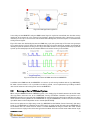
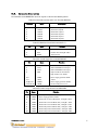
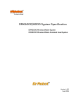
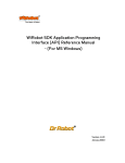
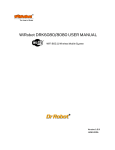
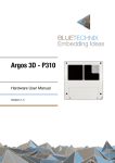
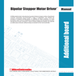
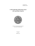
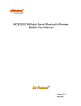
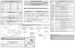
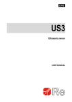
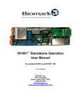
MDM5253 DC Motor Driver Module with Position and Current Feedback User Manual Version: 1.0.3 Apr. 2013 Table of Contents I. Introduction 2 II. Operations 2 II.1. Theory of Operation 2 II.2. Running as Part of WiRobot System 3 II.3. Running as a General Purpose DC Motor Driver Module 4 III. Connections 4 III.1. Board Structure 4 III.2. Connector Description 5 IV. Specifications 6 Related Document: WiRobot PMS5005 Sensing and Motion Controller User Manual Copyright © Dr Robot Inc. 2013 1 I. Introduction The MDM5253 DC Motor Driver Module with Position and Current Feedback is a three-channel H-bridge switching power amplifier board. It can be directly controlled by motion controller’s logic level PWM driving signals at a frequency up to 20 KHz. For each of the three independent channels, the MDM5253 also provides the current feedbacks and connectors for position sensors such as potentiometers. Each channel is able to drive inductive DC load with current up to 5.0 A and operating voltage ranging from 5.0 V to 28.0 V. Features 3 Independent channels Output 5.0 V to 28.0 V operations Up to 5.0 A inductive DC load current capability 5.0 V TTL/CMOS compatible Inputs PWM Frequencies up to 20 kHz Automatic PWM over-current limiting Output short circuit protection Over-temperature output current reduction and shutdown Under-voltage shutdown Analog output current feedback 3 Connectors for position feedbacks Directly plug-on to the WiRobot PMS5005 sensing and motion controller board Applications DC motor and stepper motor control Permanent magnet solenoid control Robotic systems General PWM power amplifier II. Operations II.1. Theory of Operation When four switches configured as that in Figure II.1, the whole circuit is called an H-bridge. By controlling the on/off of four switches in certain patterns, the polarity of the supply power on the control output can be changed. For example, when Control Input 1 and 4 are ON while the Control Input 2 and 3 are OFF, the controlled load is supplied by power with + on the left and – on the right. When Control Input 1 and 4 are OFF while the Control Input 2 and 3 are ON, the controlled load is supplied by power with - on the left and + on the right. When applying the H-bridge output to a DC motor or other inductive loads with PWM controlled switching command based on certain algorithms and the feedback signals, full bidirectional magnitude control, including speed, position and torque control, can be achievable. Copyright © Dr Robot Inc. 2013 2 Figure II.1 H-Bridge Switching Device In the design of the MDM5253, only one PWM control signal is required to control both the direction and the magnitude of the output for each channel. The H-bridge’s diametrical opposite pairs (control input 1 and 4, control input 2 and 3) are connected and driven HIGH and LOW together, and the two pairs are controlled with strictly inverted signals. Figure II.2 shows the relationship between the PWM duty cycle and system output. The zero average output occurs when the duty circle is 50%. The direction of the output (in speed control, for example, the direction of rotation) depends on whether the duty circle is larger than 50% or lower. The magnitude of the output (rotation speed in speed control) depends on the absolute difference between the duty circle and 50%. Figure II.2 Theoretic waveforms of PWM control for the MDM5253 In addition to the PWM control, the MDM5253 can connect up to 3 sensing feedback devices (e.g. MRS3302). DC motor control schemes, such as position and velocity control, can be implemented by installing feedback device on DC motor and connecting these devices to MDM5253. II.2. Running as Part of WiRobot System When using the MDM5253 with the WiRobot system, users simply plug the module onto one of the DC motor drive expansion connector sets on the PMS5005 Sensing and Motion Controller board (maximum of 2 MDM5253 modules are supported) and the PMS5005 on-board firmware and device driver will take care of the motor control and sensing feedback. Since PMS5005 can support 2 MDM5253, it is able to connect and control up to 6 DC motors and have 6 position sensor channels (POT1-POT6). Users have an option to use single rotary sensor (e.g. MRS3302 on the Position Sensor Connector), dual rotary sensor (e.g. 2 MRS3302 on 2 Position Sensor Connectors), or single encoder (Encoder port on PMS5005) as the feedback device to control each DC motor, if needed. PMS5005 already has built-in DC motor control schemes and users simply need to select the type of the feedback device for each DC motor. Note that for single Copyright © Dr Robot Inc. 2013 3 rotary sensor setting, DC motor 1 must use POT1, DC motor 2 must use POT2 and etc.; for dual rotary sensor setting, DC motor 1 must use POT1 and POT6, DC motor 2 must use POT2 and POT5 and DC motor 3 must use POT3 and POT4; for encoder setting, DC motor 1 must use ENCODER1 and DC motor 2 must use ENCODER2. By working with the PMS5005, users can simply call a function offered by the WiRobot SDK software on PC (requires Microsoft platform) or send a data packet (platform independent) to control the DC motors or to obtain the sensor feedback. Please refer to WiRobot SDK API Reference Manual and PMS5005 User Manual for the available motor control algorithms and schemes. II.3. Running as a General Purpose DC Motor Driver Module When using the MDM5253 with third party controllers, the power supply and the input/output signals should be connected properly (please refer to Section III for connection setting). The controller sends control commands to the enable pins and the PWM input pins based on your own control schemes and get current and position feedback data via an analog to digital converter. III. Connections III.1. Board Structure Figure III.1 shows the structure, locations and functions of the connectors on the MDM5253 module board. Figure III.1 MDM5253 Connector Locations Copyright © Dr Robot Inc. 2013 4 III.2. Connector Description The definitions of the MDM5253 connector signals are listed in the following tables. Table III.1 Connections of the Load Screw Terminals MOTOR Terminals Name 1 2 3 4 5 6 OUT1A OUT1B OUT2A OUT2B OUT3A OUT3B Description Channel #1 output A Channel #1 output B Channel #2 output A Channel #2 output B Channel #3 output A Channel #3 output B Table III.2 Position Sensor Connectors POT1 - 3 Pin Name 1 2 3 VCC3 PVS GND3 Function + 3.0 V Position data, analog 0 – 3.0 V Signal ground Table III.3 Control Signal Connector MOTOROUT Pin Name 1 2 3 4 CTL1 CTL2 CTL3 ENA 5, 6 7, 8 9, 10, 11, 12 13, 14, 15, 16 GND5 VCC5 GNDM VCCM Function Channel #1 PWM control signal Channel #2 PWM control signal Channel #3 PWM control signal Output enable for all channels: High: enable; Low: disable Power supply ground for VCC5 + 5.0 V Power supply ground for VCCM Positive load power source Table III.4 Feedback Signal Connector MOTORIN Pin 1, 2 3, 4 5 6 7 8 9 10 Copyright © Dr Robot Inc. 2013 Name VCC3 GND3 CFB1 CFB2 CFB3 PFB1 PFB2 PFB3 Function + 3.0 V, positive power source for position sensors Power supply ground for VCC3 Channel #1 current feedback data, , analog 0 – 3.0 V Channel #2 current feedback data, , analog 0 – 3.0 V Channel #3 current feedback data, , analog 0 – 3.0 V Channel #1 position feedback data, , analog 0 – 3.0 V Channel #2 position feedback data, , analog 0 – 3.0 V Channel #3 position feedback data, , analog 0 – 3.0 V 5 IV. Specifications Table IV.1 MDM5253 Specification Parameter Conditions Power Operating Voltage VCCM Switch-off Switch-on Hysteresis Logic Operating Voltage Position Sensor Power Supply Standby Supply Current VCCM VCCM UnderVoltage Shutdown Control Input HIGH Control Input LOW Enable Input Current PWM Input Current VCC5 VCC3 VENA = 0V, IOUT = 0A VENA, VCTL VENA, VCTL IENA ICTL Output-on Resistance ROUT DC Load Current Over-current Protection Over-temperature Protection PWM Frequency Output ON Delay Output OFF Delay Output Rise Time Output Fall Time Disable Delay Time Protection Turn-off Time Power-off Delay Time Position Sensor Input Range Current Feedback Sensitivity Current Feedback Accuracy Board Size Copyright © Dr Robot Inc. 2013 T = 25 ˚C T = 150 ˚C MIN 5.0 28.0 4.15 4.5 150 4.5 TYP MAX V 4.4 4.75 4.65 5.0 5.0 3.0 5.5 3.3 65 3.5 25 ±1 1.4 100 300 5.0 7.0 VCCM = 14V VCCM = 14V VCCM = 14V, IOUT = 3A VCCM = 14V, IOUT = 3A 175 10 IOUT > 1.5 A IOUT < 1.5 A V V μA μA mOhm A A ˚C 2.0 30 20 18 18 8.0 KHz μS μS μS 2.0 8.0 μS 8.0 μS μS μS V 4.0 1.0 With PMS5005 controller board V V mV V V mA 120 T < 150 ˚C Thermal shutdown Hysteresis Unit 0.0 533 ± 10 ± 20 30 x 58 5.0 3.0 mV/A % mm x mm 6