1
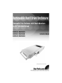
Removable Hard Drive Enclosure
Removable Drive Enclosure with Shock Absorbers
for 3.5” SATA Hard Drives
DRW110SAT, DRW110SATBK
DRW113SAT, DRW113SATBK
DRW115SAT, DRW115SATBK
Instruction Manual
Actual product may vary from photo
FCC Compliance Statement
This equipment has been tested and found to comply with the limits for a Class B digital
device, pursuant to part 15 of the FCC Rules. These limits are designed to provide
reasonable protection against harmful interference in a residential installation. This
equipment generates, uses and can radiate radio frequency energy and, if not installed
and used in accordance with the instructions, may cause harmful interference to radio
communications. However, there is no guarantee that interference will not occur in a
particular installation. If this equipment does cause harmful interference to radio or
television reception, which can be determined by turning the equipment off and on, the
user is encouraged to try to correct the interference by one or more of the following
measures:
• Reorient or relocate the receiving antenna.
• Increase the separation between the equipment and receiver.
• Connect the equipment into an outlet on a circuit different from that to which the
receiver is connected.
• Consult the dealer or an experienced radio/TV technician for help.
Use of Trademarks, Registered Trademarks, and
other Protected Names and Symbols
This manual may make reference to trademarks, registered trademarks, and other
protected names and/or symbols of third-party companies not related in any way to
StarTech.com. Where they occur these references are for illustrative purposes only and
do not represent an endorsement of a product or service by StarTech.com, or an
endorsement of the product(s) to which this manual applies by the third-party company in
question. Regardless of any direct acknowledgement elsewhere in the body of this
document, StarTech.com hereby acknowledges that all trademarks, registered
trademarks, service marks, and other protected names and/or symbols contained in this
manual and related documents are the property of their respective holders.
Instruction Manual
Table of Contents
Introduction . . . . . . . . . . . . . . . . . . . . . . . . . . . . . . . . . . . . . . . . . . . . . . . . . . . . .1
Features . . . . . . . . . . . . . . . . . . . . . . . . . . . . . . . . . . . . . . . . . . . . . . . . . . . . . . . .1
Before You Begin . . . . . . . . . . . . . . . . . . . . . . . . . . . . . . . . . . . . . . . . . . . . . . . . .1
System Requirements . . . . . . . . . . . . . . . . . . . . . . . . . . . . . . . . . . . . .1
Contents . . . . . . . . . . . . . . . . . . . . . . . . . . . . . . . . . . . . . . . . . . . . . . . .1
Installation . . . . . . . . . . . . . . . . . . . . . . . . . . . . . . . . . . . . . . . . . . . . . . . . . . . . . .2
Installing the Hard Drive in the Caddy . . . . . . . . . . . . . . . . . . . . . . . . .2
Installing the Bay in the PC . . . . . . . . . . . . . . . . . . . . . . . . . . . . . . . . .3
Installing the Swap Manager software . . . . . . . . . . . . . . . . . . . . . . . . .4
Converting a dynamic disk to a basic disk . . . . . . . . . . . . .4
Installing the Swap Manager software . . . . . . . . . . . . . . . .4
Using the Swap Manager software . . . . . . . . . . . . . . . . . . . . . . . . . . .5
Troubleshooting Swap Manager . . . . . . . . . . . . . . . . . . . . . . . . . . . . . .5
Monitoring your Hard Disk Drive and Drawer . . . . . . . . . . . . . . . . . . . .6
Technical Support . . . . . . . . . . . . . . . . . . . . . . . . . . . . . . . . . . . . . . . . . . . . . . . .7
Warranty Information . . . . . . . . . . . . . . . . . . . . . . . . . . . . . . . . . . . . . . . . . . . . .7
i
Instruction Manual
Introduction
Thank you for purchasing a StarTech.com removable Serial ATA (SATA) hard drive
enclosure with shock absorbers. Now, you can quickly add and remove SATA hard drives
from your PC without having to open your computer. Whether for hot swapping hard
drives, using multiple operating systems, making high speed, high capacity backups, or
minimizing downtime on mission-critical PCs, StarTech.com’s removable drive enclosures
provide the ultimate in reliability and convenience. The sturdy all-aluminum design gives
you extra durability and heat dissipation and the front caddy-mounted ball-bearing fan(s)
keep your hard-working drive cool.
Features
• Shock absorbers keep hard drive protected
• Compatible with all 3.5 inch SATA hard drives
• Locking mechanism controls power to the drive so that the disk cannot be
accidentally removed while in operation
• Ball-bearing fan(s) keeps hard drives running cool
Before You Begin
System Requirements
• An IBM-PC or Mac computer with an SATA Hard Drive interface
• Swap Manager software (DRW113SAT/DRW113SATBK/DRW115SAT/DRW115SATBK
ONLY) requires Windows XP/2000/Me/98SE/98/95
• Allows “hot-swapping” of drives through Swap Manager software
• One drive connection cable
• One internal power cable
Contents
This package should contain:
• 1 x drive caddy
• 1 x drive bay
• 2 x keys to lock/unlock the drive
• Screw kit
• 1 x Swap Manager software CD (DRW113SAT/DRW113SATBK/DRW115SAT/
DRW115SATBK ONLY)
1
Instruction Manual
Installation
Installing the Hard Drive in the Caddy
*Note: Mount screws to underside of drawer
1. Remove the caddy from the bay by lifting the handle and sliding the caddy out of the
bay.
2. Remove the top panel from the caddy by pressing the cover release button and sliding
the lid towards the back of the caddy.
3. Connect the SATA ribbon to the hard drive, making sure that the red wire is on Pin 1.
NOTE: If you are unsure of the location of Pin 1, contact your hard drive manufacturer.
4. Attach the power connector to the hard drive.
5. Gently place the hard drive in the caddy, making sure that the screw-holes on the
bottom of the hard drive line up with the holes in the caddy.
6. Firmly hold the hard drive to the shock absorber plate and use the four 6-32 x
1/4”(coarse thread) screws to mount your hard drive to the drawer from underneath.
7. Replace the top panel of the caddy.
2
Instruction Manual
Installing the Bay in the PC
1. Make sure your system is unplugged and you are grounded.
2. Remove the side covers from your system and remove the front cover from an
available 5 1/4” drive bay (see your computer’s user manual for details, if necessary).
3. Insert the bay into the 5 1/4” bay slot, making sure that the screw-holes on the side of
the bay line up with the holes in the bay slot.
4. Connect your computer’s cable ribbon to the connector on the back of the bay,
NOTE: Only drives that are connected to the secondary SATA controller can be
hotswapped with Swap Manager software (DRW113SAT / DRW113SATBK /
DRW115SAT / DRW115SATBK ONLY). It is not possible to hot-swap the C: or any other
drives on the primary controller.
5. Plug a connector from your computer’s power supply into the power port on the back
of the bay.
6. Using the M3 x 1/4” long (fine thread) screws, mount the bay into the PC.
Installing the Caddy in the Bay
1. With the handle lifted, slide the caddy into the bay until it is firmly seated. Lower the
handle to to click the caddy into its proper position.
2. Insert the key and turn clockwise to lock the drive into place and supply the drive with
power. The drive will not function if the drawer has not been locked.
Removing the Drive Drawer
1. Insert the key and turn counter-clockwise to unlock the drive drawer.
2. Lift the handle and gently pull the caddy out of the bay.
NOTE: Do not unlock the drawer when the hard drive is in use (See “Monitoring Your
Hard Disk Drive and Drawer” below). Only power down the drive when the hard drive is
3
Instruction Manual
idle. Once you have powered down the hard drive, wait about 15 seconds to let the hard
drive “spin down” before removing the caddy from the bay.
Installing Your Swap Manager Software
(DRW113SAT/DRW113SATBK/DRW115SAT/DRW115SATBK ONLY)
NOTE: Remember that Swap Manager only works on IBM or compatible computers
running Windows XP, 2000, Me, 98SE, 98, or 95.
NOTE: Windows 2000/XP/2003 Server users should be aware that Swap Manager does
not support the dynamic disk feature introduced in these versions of Windows. If you are
using the dynamic disk feature, you must convert the volume back to a basic disk to use
Swap Manager.
To convert a dynamic disk to a basic disk:
1. Back up all the data on all the volumes on the disk you want to convert to a basic disk.
2. Log on as Administrator or as a member of the Administrators group.
3. Click Start, and then click Control Panel.
4. Click Performance and Maintenance, click Administrative Tools, and then double
click Computer Management.
5. In the left pane, click Disk Management.
6. Right-click a volume on the dynamic disk that you want to change to a basic disk, and
then click Delete Volume.
7. Click Yes when you are prompted to delete the volume.
8. Repeat steps 4 and 5 for each volume on the dynamic disk.
9. After you have deleted all the volumes on the dynamic disk, right-click the dynamic
disk that you want to change to a basic disk, and then click Convert to Basic Disk.
NOTE: You must right-click the gray area that contains the disk title on the left side of the
Details pane. For example, right-click Disk 1.
To install the Swap Manager Software:
1.Insert your Swap Manager CD into your CD drive. If Windows does not automatically
launch the software installation, or you encounter any errors, double-click on your CD
icon and launch the SETUP file.
2. Click Next to continue the installation.
3. Select Yes, I accept to agree to the terms in the license agreement and click Next.
4. Enter a suitable location for the Swap Manager software and click Next. Click Yes to
4
Instruction Manual
confirm the location of the installation.
5. Click Finish when the installation is complete and reboot your computer to allow the
changes to take effect.
Using Your Swap Manager Software
The following is intended to provide you with an introduction to your Swap Manager
software. For detailed instructions and troubleshooting tips, consult the material provided
on the Swap Manager CD.
• Start Swap Manager by double-clicking on the Swap Manager icon. This will bring up
the Swap Manager window.
• The Swap Manager window displays a list of all the drives attached to your computer.
The window also lists information about each drive’s SATA channel.
• Remember that while the window lists all drives for your computer, you can only swap
drives attached to the secondary SATA channel.
• If possible always keep the Swap Manager open if you are planning to swap drives. It
can be minimized, but it should not be closed.
• To remove a drive, bring up the Swap Manager window and click on the Swap Out
button above the drive information. Wait a few seconds then remove the drive according
to the instructions on page 5 or according to instructions provided by the drive
manufacturer. Click on the Swap All In button to refresh the Swap Manager information.
The drive information should now be removed from the Swap Manager.
• To add a drive, add your drive according to the instructions on page 5 or according to
instructions provided by your drive manufacturer. Bring up the Swap Manager window
and click on the Swap All In button to refresh the Swap Manager. It may take a few
seconds to properly register all the new information. You should now see your new drive
listed in the Swap Manager.
Troubleshooting Swap Manager
If you have installed a new drive but there is no new icon listed in Swap Manager, first
make sure that you have clicked the Swap In icon to let Swap Manager know that there
is a new drive. If that does not work, check the following:
• Make sure that the hardware is properly installed and that all cables are properly
connected and firmly seated.
• Make sure that the drive bay is connected to the secondary SATA channel. The primary
SATA channel is not accessed by Swap Manager.
• Make sure that the drive caddy is firmly seated in the bay and that the bay has been
locked. If the bay is not locked, no power will be supplied to the drive and Swap
Manager will not detect it.
5
Instruction Manual
Monitoring Your Hard Disk Drive and Drawer
The status LED is located on the right side of the drive drawer. It is your best indication
of the hard drive’s status, and is lit when the drawer is successfully inserted and locked
into the caddy.
NOTE: It is recommended that you avoid removing a drawer during hard disk activity, as
doing so could damage the drive and/or data.
6
Instruction Manual
Technical Support
StarTech.com’s lifetime technical support is an integral part of our commitment to provide
industry-leading solutions. If you ever need help with your product, visit
www.startech.com/support and access our comprehensive selection of online tools,
documentation, and downloads.
Warranty Information
This product is backed by a one-year warranty. In addition, StarTech.com warrants its
products against defects in materials and workmanship for the periods noted, following
the initial date of purchase. During this period, the products may be returned for repair, or
replacement with equivalent products at our discretion. The warranty covers parts and
labor costs only. StarTech.com does not warrant its products from defects or damages
arising from misuse, abuse, alteration, or normal wear and tear.
Limitation of Liability
In no event shall the liability of StarTech.com Ltd. and StarTech.com USA LLP (or their
officers, directors, employees or agents) for any damages (whether direct or indirect,
special, punitive, incidental, consequential, or otherwise), loss of profits, loss of business,
or any pecuniary loss, arising out of or related to the use of the product exceed the
actual price paid for the product. Some states do not allow the exclusion or limitation of
incidental or consequential damages. If such laws apply, the limitations or exclusions
contained in this statement may not apply to you.
7
About StarTech.com
StarTech.com is “The Professionals’ Source for Hard-to-Find Computer
Parts”. Since 1985, we have been providing IT professionals with the
quality products they need to complete their solutions. We offer an
unmatched selection of computer parts, cables, server management
solutions and A/V products and serve a worldwide market through our
locations in the United States, Canada, the United Kingdom and Taiwan.
Visit www.startech.com for complete information about all our products
and to access exclusive interactive tools such as the Parts Finder and the
KVM Reference Guide. StarTech.com makes it easy to complete almost
any IT solution. Find out for yourself why our products lead the industry in
performance, support, and value.
Revised: 15 January 2007 (Rev. A)