1
HiPerCam1
High Performance Camera
User’
s Manual
Revision 1 A
Revision History
Revision
1A
Changes
Date
First Edition,
valid for hardware revision 0A, 0B, 1A
16.05.97
WARNING !
This equipment generates and can radiate radio frequencies. If not installed in
accordance with the instruction manual, it may cause interference to radio
communications. The equipment has not been tested for compliance with the limits
for class A computing devices, pursuant to subpart J of part 15 of FCC rules, which
are designed to provide reasonable protection against such interference, but
temporary usage is permitted as per regulations. Operation of this equipment in a
residential area is likely to cause interference, in which case the user, at his own
expense is required to take whatever measures may be required to shield the
interference.
DISCLAIMER!
The information in this document has been carefully checked and is believed to be
entirely reliable. However, no responsibility is assumed for inaccuracies. ELTEC
reserves the right to make changes to any products to improve reliability, function
or design. ELTEC does not assume any liability arising out of the application or
use of any product or circuit described in this manual; neither does it convey any
license under its patent rights nor the rights of others. ELTEC products are not
authorized for use as components in life support devices or systems intended for
surgical implant into the body or intended to support or sustain life. Buyer agrees
to notify ELTEC of any such intended end use whereupon ELTEC shall determine
availability and suitability of its product or products for the use intended.
ELTEC points out that there is no legal obligation to document internal
relationships between any functional modules, realized in either hardware or
software, of a delivered entity.
This document contains copyrighted information. All rights including those of
translation, reprint, broadcasting, photomechanical or similar reproduction and
storage or processing in computer systems, in whole or in part, are reserved.
EUROCOM is a trademark of ELTEC Elektronik AG. Other brands and their
products are trademarks of their respective holders and should be noted as such.
© 1997 ELTEC Elektronik AG, Mainz
User’s Manual
Table of Contents
Table of Contents
Page
Table of Contents . . . . . . . . . . . . . . . . . . . . . . . . . . . . . . . . . . . . . . . . . . . . I
List of Tables . . . . . . . . . . . . . . . . . . . . . . . . . . . . . . . . . . . . . . . . . . . . . IV
List of Figures . . . . . . . . . . . . . . . . . . . . . . . . . . . . . . . . . . . . . . . . . . . . . IV
Available Configurations . . . . . . . . . . . . . . . . . . . . . . . . . . . . . . . . . . . . . V
Related Products . . . . . . . . . . . . . . . . . . . . . . . . . . . . . . . . . . . . . . . . . . VI
Conventions . . . . . . . . . . . . . . . . . . . . . . . . . . . . . . . . . . . . . . . . . . . . . . VII
1 Specification . . . . . . . . . . . . . . . . . . . . . . . . . . . . . . . . . . . . . . . . . . . 1
1.1
Main Features . . . . . . . . . . . . . . . . . . . . . . . . . . . . . . . . . . . . . . 1
1.2
General Description . . . . . . . . . . . . . . . . . . . . . . . . . . . . . . . . . 2
1.3
Mechanical Specification . . . . . . . . . . . . . . . . . . . . . . . . . . . . . 3
1.4
Technical Details. . . . . . . . . . . . . . . . . . . . . . . . . . . . . . . . . . . .
1.4.1
CPU . . . . . . . . . . . . . . . . . . . . . . . . . . . . . . . . . . . . . .
1.4.2
DRAM Memory . . . . . . . . . . . . . . . . . . . . . . . . . . . .
1.4.3
System Flash EPROM. . . . . . . . . . . . . . . . . . . . . . . .
1.4.4
User Flash EPROM . . . . . . . . . . . . . . . . . . . . . . . . . .
1.4.5
Serial EEPROMs . . . . . . . . . . . . . . . . . . . . . . . . . . . .
1.4.6
Ethernet Interface . . . . . . . . . . . . . . . . . . . . . . . . . . .
1.4.7
Serial I/O . . . . . . . . . . . . . . . . . . . . . . . . . . . . . . . . . .
1.4.8
Parallel I/O . . . . . . . . . . . . . . . . . . . . . . . . . . . . . . . .
1.5
Video Acquisition . . . . . . . . . . . . . . . . . . . . . . . . . . . . . . . . . . . 8
1.5.1
Video A/D Converter . . . . . . . . . . . . . . . . . . . . . . . . 8
1.5.2
Video D/A Converter . . . . . . . . . . . . . . . . . . . . . . . . 8
1.5.3
CCD Sensor. . . . . . . . . . . . . . . . . . . . . . . . . . . . . . . . 8
1.5.4
Video DMA Controller . . . . . . . . . . . . . . . . . . . . . . . 9
1.5.5
Trigger Input . . . . . . . . . . . . . . . . . . . . . . . . . . . . . . 10
1.6
Connectors. . . . . . . . . . . . . . . . . . . . . . . . . . . . . . . . . . . . . . . . 11
HiPerCam1
4
5
5
6
6
6
7
7
7
I
Table of Contents (Continued)
1.7
User’s Manual
System Parameters . . . . . . . . . . . . . . . . . . . . . . . . . . . . . . . . . . 14
1.7.1
Environmental Conditions . . . . . . . . . . . . . . . . . . . . 14
1.7.2
Power Requirements . . . . . . . . . . . . . . . . . . . . . . . . 14
1.7.3
Dimensions. . . . . . . . . . . . . . . . . . . . . . . . . . . . . . . . 14
1.7.4
Regulations/Compliance . . . . . . . . . . . . . . . . . . . . . 14
1.7.5
Sensor . . . . . . . . . . . . . . . . . . . . . . . . . . . . . . . . . . . . 15
1.7.6
MTBF . . . . . . . . . . . . . . . . . . . . . . . . . . . . . . . . . . . . 15
2 Camera Control Functions . . . . . . . . . . . . . . . . . . . . . . . . . . . . . . . 17
2.1
Default Settings . . . . . . . . . . . . . . . . . . . . . . . . . . . . . . . . . . . . 24
2.2
Status Display . . . . . . . . . . . . . . . . . . . . . . . . . . . . . . . . . . . . . 25
2.3
Config-Switch . . . . . . . . . . . . . . . . . . . . . . . . . . . . . . . . . . . . . 25
3 Installation . . . . . . . . . . . . . . . . . . . . . . . . . . . . . . . . . . . . . . . . . . . . 27
II
3.1
First Steps. . . . . . . . . . . . . . . . . . . . . . . . . . . . . . . . . . . . . . . . . 27
3.2
Connect the HiPerCam1 to the Host . . . . . . . . . . . . . . . . . . . . 28
3.3
Software Configuration . . . . . . . . . . . . . . . . . . . . . . . . . . . . . . 33
3.3.1
Configuration of the HiPerCam1 . . . . . . . . . . . . . . . 33
3.3.2
Entering Boot Parameters . . . . . . . . . . . . . . . . . . . . 33
3.3.3
Configuration of the Host System . . . . . . . . . . . . . . 36
3.3.4
Configuration of the Network Interface . . . . . . . . . . 36
3.3.5
Configuration of the Tornado Cross-Development . 37
3.3.6
Generate a VxWorks boot file for the HiPerCam1 . 38
3.3.7
Booting . . . . . . . . . . . . . . . . . . . . . . . . . . . . . . . . . . . 38
3.3.8
Configuration Checklist . . . . . . . . . . . . . . . . . . . . . . 39
3.3.9
Creating Boot ROMs . . . . . . . . . . . . . . . . . . . . . . . . 40
3.4
Troubleshooting . . . . . . . . . . . . . . . . . . . . . . . . . . . . . . . . . . . . 41
HiPerCam1
User’s Manual
Table of Contents (Continued)
4 Software Development . . . . . . . . . . . . . . . . . . . . . . . . . . . . . . . . . . 43
4.1
Operating System . . . . . . . . . . . . . . . . . . . . . . . . . . . . . . . . . . 43
4.2
ELTEC Imaging API. . . . . . . . . . . . . . . . . . . . . . . . . . . . . . . . 43
4.3
Development Flow . . . . . . . . . . . . . . . . . . . . . . . . . . . . . . . . . 44
5 Demo Program . . . . . . . . . . . . . . . . . . . . . . . . . . . . . . . . . . . . . . . . 45
6 Index . . . . . . . . . . . . . . . . . . . . . . . . . . . . . . . . . . . . . . . . . . . . . . . . . 46
Support Request Form Sheet
Technical Action Request Form Sheet
HiPerCam1
III
List of Tables/Figures
User’s Manual
List of Tables
Page
Table 1:
Table 2:
Table 3:
Table 4:
Table 5:
Table 6:
Table 7:
Table 8:
Table 9:
HiPerCam1 Peripheral Connections . . . . . . . . . . . . . . . . . . . 3
CPU . . . . . . . . . . . . . . . . . . . . . . . . . . . . . . . . . . . . . . . . . . . . 5
CCIR-625 Formats . . . . . . . . . . . . . . . . . . . . . . . . . . . . . . . . . 9
EIA-525 Formats . . . . . . . . . . . . . . . . . . . . . . . . . . . . . . . . . . 9
Power Connector (12-Pin Hirose Male Connector) . . . . . . . 11
Parallel I/O Connector (9-Pin D-Sub, female). . . . . . . . . . . 11
Ethernet Connector (RJ45 Jack) . . . . . . . . . . . . . . . . . . . . . 12
Serial 2 Connector (9-Pin D-Sub, male) . . . . . . . . . . . . . . . 12
Video Output (BNC Connector) . . . . . . . . . . . . . . . . . . . . . 12
Table 10:
Table 11:
Table 12:
Serial 1 Interface (RJ12 Jack) . . . . . . . . . . . . . . . . . . . . . . . 13
Default Settings . . . . . . . . . . . . . . . . . . . . . . . . . . . . . . . . . . 24
Checklist. . . . . . . . . . . . . . . . . . . . . . . . . . . . . . . . . . . . . . . . 39
List of Figures
Page
Figure 1:
Figure 2:
Figure 3:
Figure 4:
Figure 5:
Figure 6:
Figure 7:
Figure 8:
Figure 9:
Figure 10:
IV
Block Diagram . . . . . . . . . . . . . . . . . . . . . . . . . . . . . . . . . . . . 4
Opto Coupler Circuit . . . . . . . . . . . . . . . . . . . . . . . . . . . . . . 10
Tripod Attachment . . . . . . . . . . . . . . . . . . . . . . . . . . . . . . . . 13
Status Display . . . . . . . . . . . . . . . . . . . . . . . . . . . . . . . . . . . 25
Hex Switch. . . . . . . . . . . . . . . . . . . . . . . . . . . . . . . . . . . . . . 25
Location of Switches and Connectors on the Back Panel . . 28
Connecting HiPerCam1 to Host (without Hub). . . . . . . . . . 29
10BaseT Hub Network Connection . . . . . . . . . . . . . . . . . . . 30
10BaseT/10Base2 Hub Network Connection . . . . . . . . . . . 31
10BaseT/AUI Hub Network Connection . . . . . . . . . . . . . . . 32
HiPerCam1
Available Configurations
User’
s Manual
Available Configurations
RAM
4 MB
8 MB
16 MB
CPU
PowerPC PPC 403 - 33/66 MHz
Net
10 BaseT Ethernet
Sensor
1/3”VCM3405 CCIR-625
1/3”VCM3405 EIA-525
EPROM
1 MB Flash
2 MB Flash
HiPerCam1
V
Related Products
User’s Manual
Related Products
Description:
Order No.:
Documentation
V-HPC.-A991
Hardware:
Tripod Attachment Option, 2/3”thread for photo
V-HPC1-Z001
Power Supply Option, 230 V power outlet
V-HPC1-Z002
10BaseT Twisted-pair Network Cable, Crossover,
for connection to host PC
V-HPC1-Z003
10BaseT Twisted-pair Cable, Standard, for Hub connection
V-HPC1-Z004
Serial Cable, 6-pin RJ12 to 9/25-pin (adapter included)
D-Sub female, used for Serial 1 interface
V-HPC1-Z005
Serial Cable, 9-pin D-Sub female to 9/25-pin (adapter
included) D-Sub female, used for Serial 2 interface
V-HPC1-Z006
Video Cable, 75 Ohm, BNC - BNC, 3 m
V-HPC1-Z007
Ethernet Hub, 8 10BaseT ports, AUI, Cheapernet
V-HPC1-Z008
Ethernet Card for PC, PCI
V-HPC1-Z009
Power Supply/US Version
V-HPC1-Z010
AUI Cable, 5 m
V-CABL-A112
Software:
VxWorks Cross Development Package Tornado,
with GNU C/C++, Win/NT for PC
W-VXHC-A107
HiPerCam1 BSP for Tornado with ELTEC Imaging API
W-VXHC-A106
VxWorks Runtime License for HiPerCam1
W-VXHC-A101
VI
HiPerCam1
User’
s Manual
Conventions
Conventions
If not otherwise specified, addresses are written in hexadecimal notation
and identified by a leading dollar sign ("$").
Signal names preceded by a slash ("/"), indicate that this signal is either
active low or that this signal becomes active with the trailing edge.
b
B
K
M
MHz
i
bit
byte
kilo, means the factor 400 in hex (1024 decimal)
mega, the multiplication with 100 000 in hex (1 048576 decimal)
1 000 000 Hertz
Indicates information that requires close attention.
Indicates critical information that is essential to read.
!
Indicates information that is imperative to read. Skipping
this material, possibly causes damage to the system.
HiPerCam1
VII
User’s Manual
VIII
HiPerCam1
1 Specification
1 Specification
1 Specification
1.1 Main Features
• HiPerCam1: camera with built-in image processing computer.
• Smart camera complete with CCD, local CPU, and network connectivity.
• PowerPC processor with 30 ... 60 k Dhrystone, 40 ... 80 MIPS.
• Real-time acquisition of images directly into local memory for optimum
CPU access.
• On-board ADC, input look-up table and DAC for video output.
• Complete interface equipment: two serial ports, Ethernet, digital I/O port,
trigger input, video output.
• Basic software: VxWorks development system Tornado with GNU
C/C++ compiler.
• ELTEC Imaging API.
HiPerCam1
1
Main Features
User’
s Manual
1 Specification
User’s Manual
1 Specification
General Description
1.2 General Description
HiPerCam1 is the first of a growing number of intelligent cameras from
ELTEC. It is a complete CCD-based matrix camera with an intelligent
frame grabber together in a small housing.
HiPerCam1 contains everything that is needed for image processing. A
PowerPC CPU, peripherals optimized for embedded control applications,
fast image and program memory, Flash EPROM, nonvolatile memory,
video output, connectivity via Ethernet or RS-232, and our proven
professional frame grabber logic.
On-board I/O is intended to communicate with an external computer
through the serial connection as well as triggering flashlights with the
parallel I/O bits. The Ethernet interface can transfer images or image
processing results for remote display or is used for software download.
The on-board DAC drives an analog video output, supplied for adjustment
purposes; it shows the incoming analog video signal when acquisition is
on or the stored images when acquisition is off.
Video input data is stored in main memory (RAM) via an on-board DMA
controller. It can store video data at video rates in four possible formats
each for CCIR-625 or EIA-525. Pixels are acquired synchronously to the
camera clock. Smaller image fields (512 hor. e.g.) are centered, edges are
left out.
The DMA controller is used to display live image or stored image data
from local memory at the video output.
Video line pitch is the same as video line length to conserve memory lines are tightly packed.
2
HiPerCam1
1 Specification
User’
s Manual
The HiPerCam1 case has a small cross-section of 60 mm x 60 mm and a
length of 150 mm, making it possible to stack several HiPerCams in
space-constrained applications. The camera has a C-mount thread for
lenses; all electrical connections are routed to the HiPerCam1’s back
panel.
Table 1: HiPerCam1 Peripheral Connections
Connector
Connector Type
Signals
Data Rate
Digital I/O
9-pin D-Sub, female
8-bit TTL parallel I/O,
IOH = 3 mA, IOL=10 mA
500 ns/IO
Serial I/O 1
RJ12
RS-232 serial (RXD,
TXD, RTS, CTS)
Serial I/O 2
9-pin D-Sub, male
RS-232 serial (RXD,
TXD, RTS, CTS, DTR,
DCD, DSR, RI)
Power
Hirose 12-pin circular
+12V, trigger, video
synchronization
-
Analog
video output
BNC
Composite video signal
1 VPP ,
CCIR-625/EIA-525
14.3 MPixel/s
bandwidth
Ethernet
RJ45
10BaseT
10 Mbps
Lens
C-mount
n.a.
-
Status
-
CPU activity,
acquisition, Ethernet,
Serial 2
-
HiPerCam1
300 bps ...
115 kbps
3
Mechanical
1 Specification
1.3 Mechanical Specification
1 Specification
User’s Manual
1.4 Technical Details
Technical Details
1 Specification
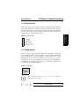
Figure 1: Block Diagram
CCD Sensor
Video ADC
8-bit + LUT
8 Data
Video out
DAC 8-bit
BNC
8
Video output
Video Data
FIFO
Data 0...32
System EPROM
256 KB
Video In/Out
DMA Controller
SystemEEPROM
512 B
User
Flash EPROM
1 MB, 2 MB
Control
DRAM
Instr., Data, Images
4, 8, 16 MB
User EEPROM
512 B
8-bit Parallel
Input/Output
Parallel I/O
Hex
Switch
Status Indicator
CPU busy
Acquisition
Ethernet
Serial 2
Ethernet
Controller
Ethernet
10BaseT
IBM PPC403
Serial 2
PowerPC
CPU
Serial 2
Controller
RXD, TXD, RTS, CTS
DTR, DCD, DSR, RI
Power
Supply
/HSYNC, /VSYNC
TRIG+, TRIG-
Serial 1
Interface
Serial 1
RXD, TXD, RTS, CTS
4
HiPerCam1
1 Specification
User’
s Manual
The HiPerCam1 CPU chip is a member of the PowerPC family of RISC
processors. It is a full PowerPC with on-chip peripherals optimized for
embedded control.
Table 2: CPU
CPU
IBM PowerPC 403 GA/GCX
Compatibility
PowerPC family
Clock
33 MHz/66 MHz clock-doubled CPU opt.
Performance
40/80 MIPS
Power consumption
0.2 W/0.4 W
Caches
1K data, 2K instructions/8K data, 16K instr.
Data bus width
32
The PPC403 is a 32-bit RISC embedded controller with a specific
implementation of the PowerPC architecture. The PPC403 consists of a
highly pipelined processor core and several peripheral interface units as
DMA controller, serial interface, asynchronous interrupt controller and
programmable interval and watchdog timers.
1.4.2 DRAM Memory
The DRAM on the HiPerCam1 is used for data, instruction and video data.
The memory is built by a standard 72-pin SO-DIMM. Memory sizes of 4,
8, and 16 MB are supported. The memory modules have to be 5 V types
with 60 ns access time.
HiPerCam1
5
Technical Details
1 Specification
1.4.1 CPU
1 Specification
User’s Manual
1.4.3 System Flash EPROM
Technical Details
1 Specification
The HiPerCam1 comes with a ROM-based firmware monitor for system
initialization, basic debug, download and network configuration. This
firmware monitor is held in the system EPROM. To come up with the
system firmware, the hex switch on the back panel has to be switched to
position ’1’.
1.4.4 User Flash EPROM
The operating system together with user code can be programmed into the
user Flash EPROM of the HiPerCam1. Monitor and debug kernel reside in
the system EPROM, so there is no danger of corrupting vital system
firmware while reprogramming the Flash EPROM. The user EPROM
offers up to 2 MB program and data storage.
When the hex switch on the back panel is switched to any other odd
position than ’1’, the HiPerCam1 comes up user-defined. Application can
start image processing immediately after power-on or reset without any
necessary download. So, the HiPerCam1 can be installed as a stand-alone
image processing system.
1.4.5 Serial EEPROMs
On the HiPerCam1 two serial EEPROMs are available. One of these
EEPROMs is used to store the system configuration and specific board
parameters. The second EEPROM can be used by the user to store any
data up to 512 B. To program the EEPROM, use special HiPerCam1
software functions.
6
HiPerCam1
User’
s Manual
1 Specification
The 10BaseT Ethernet interface offers a communication link with high
transfer rates and long distances (10 Mb/s, 100 m). So, the HiPerCam1 can
be connected via Ethernet to a 10BaseT hub, which offers network links to
other HiPerCams in the network and a host computer.
1.4.7 Serial I/O
The HiPerCam1 offers two serial interfaces Serial 1 and Serial 2. The
Serial 1 interface is directly linked to the embedded PowerPC controller
PPC403. This interface can be connected via a RJ12 jack on the back
panel. Supported communication lines are Receive (RXD), Transmit
(TXD), Request To Send (RTS) and Clear To Send (CTS). Software and
hardware handshake is possible. Baud rates of 300 bps up to 115 kbps are
supported.
The Serial 2 interface can be connected via a standard 9-pin D-Sub male
connector on the back panel. This interface allows full RS-232
communication as necessary for modem support. Supported data lines are
RXD, TXD, RTS, CTS, Data Terminal Ready (DTR), Data Set Ready
(DSR), Data Carrier Detect (DCD) and Ring Indicator (RI).
1.4.8 Parallel I/O
On the back panel of the HiPerCam1 a 9-pin D-Sub female connector
offers eight user configurable TTL I/O lines.
The port lines 0/1, 2/3, 4/5, 6/7 can be configured in pairs as input or
output.
The parallel I/O is handled via specific library functions which offer input/
output configuration and port read/write operations.
HiPerCam1
7
Technical Details
1 Specification
1.4.6 Ethernet Interface
1 Specification
User’s Manual
1.5 Video Acquisition
Video Acquisition
1 Specification
1.5.1 Video A/D Converter
The video analog to digital converter is an 8-bit converter with a sampling
rate up to 20 Msamples/s. The A/D converter also includes a 256 B x 8-bit
look-up table (LUT). The LUT is applicable for signal correction and
binarization. The look-up table can be initialized via a standard API
function.
1.5.2 Video D/A Converter
The video D/A converter is used to display the live video data of the
camera or the video data stored in the DRAM at a standard CCIR/EIA
monitor. The maximum output voltage is 1 VPP at 75 Ohm.
1.5.3 CCD Sensor
The HiPerCam1 is available with different built-in sensors: Modules for
interlaced acquisition with optional square pixel format and restart are
available. Features of the Philips VCM3405 include: programmable or
auto gain, shutter speed 1/50 ... 1/12000 s, electronic iris with 1/2000 ... 1/
100000 s exposure time, backlight compensation, gamma correction, noninterlaced operation, field/frame integration – all configurable by
software. The electrical camera interface matches the sensor: a flash ADC
with 14.3/12.5 Msamples/s is used for pixel-synchronous conversion;
thus, subpixel computations are easy. Standard lenses are attached with a
C-mount thread.
8
HiPerCam1
1 Specification
User’
s Manual
The video DMA controller is used to store the incoming video data at
video rates into the local memory. Four possible formats each for
CCIR-625 and EIA-525 are implemented.
Table 3: CCIR-625 Formats
Dot clock
MHz
Image
Size
Format
Images stored in
4 / 8 / 16 MB without OS
14.3
768 x 568
CCIR full, double field
8 / 16 / 32
14.3
512 x 512
CCIR reduced, double field
15 / 30 / 60
14.3
768 x 284
CCIR full, single field
17 / 34 / 68
14.3
512 x 256
CCIR reduced, single field
30 / 60 / 120
Table 4: EIA-525 Formats
Dot clock
MHz
Image
Size
Format
Images stored in
4 / 8 / 16 MB without OS
14.3
768 x 480
EIA full, double field
10 / 20 / 40
14.3
512 x 480
EIA reduced, double field
16 / 32 / 64
14.3
768 x 240
EIA full, single field
21 / 42 / 84
14.3
512 x 240
EIA reduced, single field
32 / 64 / 128
While acquisition is active, the live image is displayed at the video output.
The same DMA controller can also be used to display stored data at the
video output.
i
Either the video acquisition mode can be active - transferring
video data from the CCD module to the local memory -, or the
video display mode can be active - transferring video data
from the local memory to the video output. Both modes can
not operate simultaneously.
The base address to store the video image can be programmed into the
video base address register in steps of 128 KB with API functions.
HiPerCam1
9
Video Acquisition
1 Specification
1.5.4 Video DMA Controller
1 Specification
User’s Manual
1.5.5 Trigger Input
Video Acquisition
1 Specification
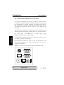
The trigger input is opto-decoupled and occupies two pins on the 12-pin
power connector. The two pins are connected to the anode and cathode of
the LED in the opto coupler circuit (Figure 2: ‘Opto Coupler Circuit’).
Therefore, the external signal is totally independent of the internal signal
level. An opto-decoupled trigger provides much better noise immunity
than conventional TTL devices.
Figure 2: Opto Coupler Circuit
TRIG+
220 Ω
TRIG–
opto coupler circuit
10
HiPerCam1
1 Specification
User’
s Manual
Table 5: Power Connector (12-Pin Hirose Male Connector)
Pin
Signal
1
GND
2
+12V Power Supply
3
GND
4
NC
5
GND
6
/HSYNC input/output
7
/VSYNC input/output
8
TRIGGER input, TRIG–, max. 20 mA
9
NC
11
NC
12
GND
13
+12V Power Supply
8
10
3
11
4
TRIGGER input, TRIG +, max. 20 mA
10
9
1
2
7
12
6
5
Front View
Table 6: Parallel I/O Connector (9-Pin D-Sub, female)
Pin
Signal
1
I/O Port bit 0
2
I/O Port bit 1
3
I/O Port bit 2
4
I/O Port bit 3
5
I/O Port bit 4
6
I/O Port bit 5
7
I/O Port bit 6
8
I/O Port bit 7
9
GND
5
1
9
6
Front View
HiPerCam1
11
Connectors
1 Specification
1.6 Connectors
1 Specification
User’s Manual
Table 7: Ethernet Connector (RJ45 Jack)
Connectors
1 Specification
Pin
Signal
1
Transmit, TX+
2
Transmit, TX-
3
Receive, RX+
4
NC
5
NC
6
Receive, RX-
7
NC
8
NC
1
8
Front View
Table 8: Serial 2 Connector (9-Pin D-Sub, male)
Pin
Signal
1
Data carrier detect, DCD
2
Receive data, RXD
3
Transmit data, TXD
4
Data terminal ready, DTR
5
GND
6
Data set ready, DSR
7
Request to send, RTS
8
Clear to send, CTS
9
Ring indicator, RI
1
5
6
9
Front View
Table 9: Video Output (BNC Connector)
Pin
Signal
1
Video output
2
GND
1
2
Front View
12
HiPerCam1
1 Specification
User’
s Manual
Signal
1
1
Request to send, RTS
2
Transmit data, TXD
3
GND
4
GND
5
Receive data, RXD
6
Clear to send, CTS
6
Front View
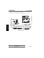
Figure 3: Tripod Attachment
M2 thread
M2 thread
1/4 UNC-20
M6 thread
M6 thread
V-HPC1-Z001
M2 thread
M2 thread
HiPerCam1
13
Connectors
Pin
1 Specification
Table 10: Serial 1 Interface (RJ12 Jack)
1 Specification
User’s Manual
1 Specification
System Parameters
1.7 System Parameters
1.7.1 Environmental Conditions
• Storage Temperature:
-25 °C to +85 °C
• Operating Temperature:
0 °C to +45 °C (non condensing)
• Maximum Operating Humidity:
85% relative
1.7.2 Power Requirements
• Input voltage range 9 V ... 25 V DC (stabilized, ripple <10%)
• Typ. 550 mA at 12 V, max. 650 mA
• Typ. 6.6 W, max. 8 W
1.7.3 Dimensions
• 60.8 mm x 60.8 mm x 150 mm (without lens, tripod attachment,
protrusion of connectors at back panel)
• Weight:
approx. 650 g
1.7.4 Regulations/Compliance
• CE
14
HiPerCam1
•CCIR:
720 x 568 pixel
•EIA:
736 x 480 pixel
•Horizontal resolution
(TV lines)
560
•CCIR vertical resolution
(field integration mode, TV lines)
415
1 Specification
1.7.5 Sensor
•CCIR vertical resolution
485
(frame integration mode, TV lines)
1.7.6 MTBF
•7538 h (computed after MTL HDBK-217E)
•101009.2 h (realistic value from industry standard experience)
HiPerCam1
15
System Parameters
1 Specification
User’
s Manual
1 Specification
1 Specification
System Parameters
16
HiPerCam1
User’s Manual
User’
s Manual
2 Camera Control Functions
2 Camera Control Functions
The on-board camera control logic hardware makes versatile camera
features possible. These functions are discussed in this chapter. All
functions are supported by API functions.
2 Camera Control
Functions
The Philips CCD sensor module offers several features which all can be
controlled via ELTEC API function interface.
Synchronization
The 12-pin Hirose connector offers /HSYNC and /VSYNC signals for
camera synchronization. These signals can be used as outputs of the
internal camera timing or as inputs for synchronization from external sync
source. Usage as input or output is selected via an API function. In case of
external synchronization there are four possible modes:
!
The hardware can be damaged when /HSYNC, /VSYNC
signals at the 12-pin Hirose connector are set to output
and an external source also drives these signals. By default
these signals are set to input.
•Reset/Restart
An external trigger impulse at TRIG+/TRIG- of the 12-pin Hirose
connector leads to a camera Restart/Reset if the Restart/Reset feature is
enabled by software.
If the Restart feature is enabled, an external trigger signal restarts the
camera (timing of the CCD module is reset) and starts the acquisition.
So no frame delay occurs for triggered snapshots.
HiPerCam1
17
2 Camera Control Functions
User’s Manual
• V- lock
In this mode the camera is synchronized in vertical direction. This mode
is also called line lock.
For this mode a negative V-reset pulse has to be applied to the camera
via the /HSYNC input. The amplitude of the pulses that are supplied to
the camera should has to be TTL-level.
2 Camera Control
Functions
The V-reset timing has to be as follows:
field 1
field 2
V-reset
EIA: 262.5 lines
CCIR: 312.5 lines
10 lines ± 5 lines
• Synclock with V-reset
In this mode the camera can lock to a composite sync signal if also a
V-reset is applied to the camera. The composite sync pulses have to be
fed to the camera via the /HSYNC input, the V-reset pulses via the
/VSYNC input.
The amplitude of the pulses that are supplied to the camera have to be
TTL.
The composite pulse has to be a negative pulse as follows (vertical pulse
components not shown):
1H-line time approx. 64 µs
For requirements of the V-reset signal, see description to mode V-lock.
18
HiPerCam1
2 Camera Control Functions
User’
s Manual
2 Camera Control
Functions
•H- and V-lock
In this mode the camera is locked in vertical and horizontal direction to
the external timing. The external HSYNC and VSYNC pulses have to be
applied via the /HSYNC and /VSYNC inputs correspondingly. The
amplitude of the pulses that are supplied to the camera has to be TTL. It
is very important that the falling edge of the V-pulse comes within half a
line after the falling edge of the H-pulse.
The external HSYNC and VSYNC timing parameters have to be as
follows:
6.3 µs ± 2 µs
ext. H
max. 1/2 line time between
rising edge H and falling edge V
ext. V
nominal time V=low -> 10H-lines ± 5 lines
HiPerCam1
19
2 Camera Control Functions
User’s Manual
Shutter speed
2 Camera Control
Functions
The camera offers several integration modes. It is possible to select eight
fixed shutter times. In the electronic exposure mode, an auto exposure
circuit adapts the shutter speed to the brightness of the scene. This
feature is intended for surveillance systems, while the fixed shutter
mode meets requirements of industrial machine control. The following
table shows the different shutter speeds:
Mode
Shutter Speeds
1/60 s (EIA), 1/50 s (CCIR)
1/100 s (EIA), 1/120 s (CCIR)
1/250 s
Fixed Shutter Mode
1/500 s
1/1000 s
1/2000 s
1/5000 s
1/10000 s
min ss: 1/100.000
Electrical Exposure Mode
(electronic iris)
min ss: 1/39.000
start ss: 1/100.000
start ss: 1/2000
Field/Frame integration
In field integration mode every line is exposed 20 ms for CCIR and
16.6 ms for EIA. In field one the lines 1 and 2, 3 and 4, 5 and 6 etc. are
added up and in field two the lines 2 and 3, 4 and 5, 6 and 7 etc. are
added up. So each line is used twice, once in field one and once in field
two. In field integration mode the vertical resolution is 415 TV lines
(CCIR).
In frame integration mode every line is exposed 40 ms for CCIR
(33.33 ms for EIA) In field one only the odd lines are coming out of the
CCD. The even lines will be exposed for an extra 20 ms (16.6 ms). So
after an extra field period the even lines are coming out. The vertical
resolution in this mode is 485 TV lines (CCIR).
20
HiPerCam1
User’
s Manual
2 Camera Control Functions
Line mode
Line mode is a special CCD-sensor mode. Line mode can be set to
interlaced (normal operation mode) or noninterlaced. In the
noninterlaced mode field one and field two are equal to each other. The
lines 1 and 2, 3 and 4, 5 and 6 etc. are combined to build a single line.
2 Camera Control
Functions
i
In this mode the pixel arrays are rectangular and the vertical
resolution is reduced to half.
Gamma correction
Gamma is a nonlinear function in the camera to compensate the
nonlinear behavior of the monitor. Normal gamma coefficient is 0.45.
For pattern recognition a linear behavior is often more useful, so the
gamma correction can be switched off.
Backlight compensation
Backlight compensation can be quite useful if the main object of the
scene is in front of a very bright background. So the main subject can
become very dark and difficult to recognize. In normal mode the auto
exposure control loop measures the average signal of the complete
image. In backlight compensation mode only the bottom part of the
scene is taken into account for the auto exposure control loop.
Gain
The camera has a gain control logic. So auto gain and fixed gain control
is possible. Using auto gain the video output signal is kept at 1 VPP over
a certain illumination range. For normal gain mode the gain of the
output can be individually adjusted by the user. Adjustment range is 0 ...
+16 dB.
HiPerCam1
21
2 Camera Control Functions
User’s Manual
Double field/single field acquisition
With this feature a single field acquisition mode or a two field
acquisition mode is selectable. The difference between the two modes is
as follows:
For single field acquisition each field is in one frame.
2 Camera Control
Functions
In the double field acquisition mode, a frame consists of an even and an
odd field. In the local memory the image is stored in linear which means
after an even line follows an odd line and vice versa.
Field ordering
The field acquisition order can be set to even-odd ordering or can be set
to don’t care.
Acquisition window size
For CCIR a window size of 768 x 582 (full acquisition window, double
field), 768 x 291 (full acquisition window, single field), 512 x 512
(reduced acquisition window, double field), 512 x 256 (reduced
acquisition window, single field) is selectable. For EIA a window size of
768 x 492 (full acquisition window, double field), 768 x 246 (full
acquisition window, single field), 512 x 480 (reduced acquisition
window, double field), 512 x 240 (reduced acquisition window, single
field) is selectable. The pitch size is 512 for a reduced acquisition
window size and 768 for a full acquisition window size.
i
For window size of 768 pixels per line:
EIA sensor:
32 invalid pixels at each start of a line
CCIR sensor: 48 invalid pixels at each start of a line
Enable DMA function
This feature enables or disables the video DMA transfers. The DMA
transfers have to be enabled to store image data into the memory or to
display image data at the video output.
22
HiPerCam1
User’
s Manual
2 Camera Control Functions
DMA transfer direction
The transfer direction of the video DMA transfers has to be set to
display video data on the video output or to store the image data into the
local memory.
2 Camera Control
Functions
i
It is either possible to display stored video data on the video
output (DMA transfer direction is from local memory to video
display unit) or to store incoming video data to the local
memory (DMA transfer direction is from video acquisition
unit to local memory). Both possibilities cannot be used
simultaneously.
It is recommended to set the DMA direction only when no the
DMA transfers are active (DMA transfers disabled) else video
data could be corrupted.
Interrupt control
The HiPerCam1 offers video API function which displays the following
status conditions:
-
Acquisition running / No acquisition running
Acquisition finished / No acquisition finished
VSYNC active / VSYNC inactive
Odd field active / Even field active
Video interrupts can be generated for the CPU on the following
conditions:
- Interrupt triggered when acquisition is finished
- Interrupt triggered when VSYNC is active
The video interrupts are connected to interrupt line (/IRQ3) and critical
interrupt input (/CINT) of the CPU.
HiPerCam1
23
2 Camera Control Functions
User’s Manual
2.1 Default Settings
Table 11: Default Settings
2 Camera Control
Functions
24
Function
Default Setting
Acquisition window size
Reduced acquisition size
Two field/single field acquisition
Single field
Field ordering
even - odd
Enable DMA function
Disabled
DMA transfer direction
Acquisition into to memory
Interrupt control
Interrupt disabled
Line mode
Interlaced
Gamma correction
Off
Backlight compensation
Off
Gain
Minimal gain
Field/Frame integration
Field integration
Shutter speed
1/50 s CCIR; 1/60 s EIA
Synchronization
Internal Synchronization
HiPerCam1
User’
s Manual
2 Camera Control Functions
2.2 Status Display
2 Camera Control
Functions
On the back panel of the HiPerCam1 four LEDs indicate the operating
status of the HiPerCam1. The upper LED signals that the CPU is running.
The LED below shows video acquisition activity. The next LED indicates
transfers on the Ethernet interface and the LED at the bottom is flickering
during transfers via the Serial 2 interface.
Figure 4: Status Display
CPU active
Acquisition on
Ethernet active
Serial line 2 active
2.3 Config-Switch
The hex switch on the back panel defines the configuration source and
special operation modes. Switch position ’1’ is the default setting and
forces the HiPerCam1 to come up with the system monitor of the system
EPROM. All other non-reset positions are reserved for user specific
configuration. In that case the HiPerCam1 uses the user Flash EPROM as
boot ROM. As an example at time of delivery a stand-alone VxWorks OS
is installed in the user Flash EPROM.
Figure 5: Hex Switch
CD
AB E
45
23 6
F01
78 9
i
All even switch positions (0, 2, 4, 6, 8, A, C, E) hold the
HiPerCam1 in reset state.
HiPerCam1
25
2 Camera Control Functions
2 Camera Control
Functions
26
HiPerCam1
User’s Manual
3 Installation
User’
s Manual
3 Installation
3.1 First Steps
• Carefully remove the camera from the shipping carton.
• Save the original shipping container and packing material for storing or
reshipping the camera.
• Inspect the camera for any shipping damage. If undamaged, the camera
can be prepared for system installation.
• Make sure that the hex switch is in position 1.
- Connect the serial 1 interface to your terminal/host.
- Connect the HiPerCam1 via 10BaseT to your host.
• Configure the host and the HiPerCam1 as described in Section 3.3
‘Software Configuration’.
HiPerCam1
27
First Steps
3 Installation
• Connect the HiPerCam1 as shown in Figure 7, 8, 9.
3 Installation
User’s Manual
3.2 Connect the HiPerCam1 to the Host
To connect the HiPerCam1 to the host the serial 1 interface must be
connected to an ASCII terminal or emulator. Otherwise no HiPerCam1
boot configuration is possible. Therefore use ELTEC serial cable VHPC1-Z005. Also a network connection from the HiPerCam1 to the host
system must be installed as shown in Figures 7, 8, 9 to allow boot file
download.
The HiPerCam1 can be directly connected to the host via a special crossed
10BaseT network cable (ELTEC V-HPC1-Z003). So, no hub is necessary.
For power supply of the HiPerCam1 use ELTEC power supply
V-HPC1-Z002 (US version: V-HPC1-Z010).
Before starting the HiPerCam1 make sure that the configuration of the
host and the HiPerCam1 is correct. Therefore refer to Section 3.3
‘Software Configuration’.
Figure 6: Location of Switches and Connectors on the Back Panel
Parallel
Network
Serial 2
F01
Video
28
Serial 1
456
A
23
BC D E
Power
78 9
Connect the
3 Installation
A video monitor should be connected to the HiPerCam1. After power-on a
live image can be seen on the monitor.
Config Status
HiPerCam1
3 Installation
User’
s Manual
Figure 7: Connecting IHiPerCam1 to Host (without Hub)
Target System
Host System
Power Supply
(V-HPC1-Z002/Z010)
Monitor
230V/50Hz=Z002
110V/60Hz=Z010
Parallel
Network
Serial 2
Video Serial 1 Con. Stat
V-HPC1-Z005
COM2
Video Cable
V-HPC1-Z007
COM1
Serial
Interface
9-pin D-Sub
Video
Monitor
(CCIR/EIA)
10Base2
AUI
10BaseT
Network
Interface
V-HPC1
-Z009
10BaseT crossed Cable
V-HPC1-Z003
HiPerCam1
29
Connect the
Power
3 Installation
Mouse
3 Installation
User’s Manual
Figure 8: 10BaseT Hub Network Connection
V-HPC1-Z009
Network
10Base2
Connect the
3 Installation
10BaseT Standard Cable
(V-HPC1-Z004)
10BaseT Standard Cable
(V-HPC1-Z004)
10BaseT
10Base2
Hub ( V-HPC1-Z008)
30
10BaseT
AUI
HiPerCam1
AUI
3 Installation
User’
s Manual
Figure 9: 10BaseT/10Base2 IHub Network Connection
V-HPC1-Z009
10Base2
10BaseT
AUI
10BaseT
10Base2
3 Installation
10BaseT Standard Cable
(V-HPC1-Z004)
AUI
Hub (V-HPC1-Z008)
i
Take care that the 10Base2 network connection is correctly
terminated at both ends.
HiPerCam1
31
Connect the
Network
3 Installation
User’s Manual
Figure 10: 10BaseT/AUI Hub Network Connection
V-HPC1-Z009
Network
10Base2
Connect the
3 Installation
10BaseT Standard Cable
(V-HPC1-Z004)
10BaseT
AUI Cable
(V-CABL-A112)
10BaseT
10Base2
Hub (V-HPC1-Z008)
32
AUI
HiPerCam1
AUI
3 Installation
User’
s Manual
3.3 Software Configuration
To become familiar with the HiPerCam1 family, the host and the
HiPerCam1 should be configured for the first steps as described in this
section. First the VxWorks Tornado cross development should be installed
on the host (see Tornado User’s Guide) with the BSP/API package
supplied by ELTEC for the HiPerCam1.
3.3.1 Configuration of the HiPerCam1
3 Installation
When you power on the HiPerCam1 (and each time you reset it), the
HiPerCam1 starts from system EPROM (hex switch position 1). During
the boot process, the camera uses its serial port to communicate with your
terminal or the terminal emulation (default VT100) of the workstation.
The boot program first displays the ROM BSP version, and then starts a
seven-second countdown, visible on the screen. Unless you press any key
on the keyboard within that seven-second period VxWorks boots
automatically with a default configuration.
To change the boot configuration, first power on (or reset) the target; then
stop the boot sequence by pressing any key during the countdown. The
boot program displays the VxWorks boot prompt, as follows:
[VxWorks Boot]:
3.3.2 Entering Boot Parameters
Before booting VxWorks, you have to set the configuration parameters for
the boot, including the host and target network addresses, the file to be
booted, the user name, and so on.
HiPerCam1
33
Software
If you have correctly configured your host software and target hardware,
you are ready to turn on the target system power and boot VxWorks.
3 Installation
User’s Manual
The VxWorks boot program provides a limited set of commands. To see a
list of available commands, type the help command (h or ?) followed by
<Enter>. For more detailed description of the commands, see the Wind
River Systems Tornado User’s Guide.
To display the current boot parameters, type 'p' at the boot prompt, as
follows:
[VxWorks Boot]: p
A display similar to the following appears; the meaning of each of these
parameters is described in the next section. The 'p' command does not
actually display blank fields, although this example shows them for
completeness.
Software
3 Installation
boot device
: nicHPC
processor number
: 0
host name
: hpchost
file name
: /tornado/target/config/HiPerCam1/vxWorks
inet on ethernet (e)
: 195.0.0.201
inet on backplane (b) :
host inet (h)
: 195.0.0.200
gateway inet (g)
:
user (u)
: HiPerCam1
ftp password (pw) (blank=use rsh) : 403
flags (f)
: 0x0
target name (tn)
:
startup script (s)
:
other (o)
:
To change the boot parameters, type 'c' at the boot prompt:
[VxWorks Boot]: c
In response, the boot program prompts you for each parameter. If a
particular field has the correct value already, press <Enter>. To clear a
field, enter a period (.), then press <Enter>. If you want to quit before
completing all the parameters, type <CTRL> + D.
34
HiPerCam1
User’
s Manual
3 Installation
Network information has to be entered to match your particular system
configuration. The 'inet' addresses has to match those in your system’s
hosts file (or those known to your Domain Name Server), as described in
the Wind River Systems Tornado User’s Guide.
The name of the host machine to boot
from. This is the name by which the host
is known to VxWorks; it need not be the
name used by the host itself (hpchost).
file name
The full pathname of the VxWorks object
module to be booted (/tornado/target/
config/HiPerCam1/vxWorks).
This
pathname is also reported to the host when
you start a target server, so that it can
locate the host-resident image of
VxWorks.
inet on ethernet (e) The Internet address of the HiPerCam1
with an Ethernet interface (195.0.0.201).
host inet (h)
The Internet address of the host to boot
from (195.0.0.200).
user (u)
The user name that VxWorks uses to
access the host (HiPerCam1 in the
example); that user must have permission
to read the VxWorks boot-image file.
VxWorks must have access to this user’s
FTP sign on, with the FTP password
provided below.
ftp password (pw)
The 'user' password. This field is not
required by the boot program, but you
must supply it to boot over the network
HiPerCam1
35
Software
host name
3 Installation
Necessarily the boot configuration parameters have to be changed
corresponding to your system environment.
3 Installation
User’s Manual
from a Windows host. (If you do not
supply this password, the boot ROM
attempts to load the run-time system
image using a protocol based on the UNIX
rsh utility, which is not available for
Windows hosts.)
The boot parameters are stored in the system EEPROM and retain even if
power is turned off. For each subsequent power-on or system reset, the
boot program uses these stored parameters for the automatic boot
configuration.
3.3.3 Configuration of the Host System
Software
3 Installation
The HiPerCam1 is connected to the host’s system via an ethernet 10BaseT
interface (shielded twisted-pair) and a serial interface. The serial interface
is used as a terminal (default ASCII terminal configuration is 9600 bps, 8
data bits, no parity, one stop bit, protocol Xon/Xoff) connection to set the
boot parameters on the HiPerCam1 as described in Section 3.3.2 ‘Entering
Boot Parameters’. The network interface is mainly used for program
downloads and data transfers between the host and the HiPerCam1.
3.3.4 Configuration of the Network Interface
The network interface of the host system has to support the TCP/IP
protocol. Therefore it is necessary to add this protocol type into the
network configuration setup. For correct message transfers, a network IP
address has to be declared and a host name has to be defined for the host
network interface. If these parts are done, make sure that the host IP
address and the host name correspond to the entries specified in the
HiPerCam1 boot parameter configuration (default setting: host IP
address:195.0.0.200, host name: hpchost). Make sure that the user name is
known to the host and has permission to access files in the specified
directory.
36
HiPerCam1
User’
s Manual
3 Installation
3.3.5 Configuration of the Tornado Cross-Development
!
For Windows NT or UNIX the host system built-in FTP
server has to be used. For configuration, refer to the
Windows NT/UNIX system manual.
For Windows 95 systems the FTP server is included in the Tornado 1.0
Development Package and has to be configured as shown. This description
refers to Tornado 1.0 and could be subject to change in the next version.
• Open the WFTPD window and select the Users/rights command from the
security menu.
• Via the New User button a user name can be entered which has to
correspond to that declared in the HiPerCam1 boot parameter
configuration (default setting: hipercam1).
• A password has to be specified which has to correspond to that declared
in the HiPerCam1 boot parameter configuration (default setting: 403).
• A home directory has to be defined in the home directory text box (useful
setting: C:\).
• In the submenu Rights >> enter * in the directory text box.
• The configuration is saved by clicking the button done.
HiPerCam1
37
Software
!
These programs are mandatory for working with Tornado
and HiPerCam1. Also an FTP server has to be started to
allow network connectivity.
3 Installation
Tornado is the integrated environment for software cross-development for
the HiPerCam1. The Tornado environment provides an efficient way to
develop real-time and embedded applications. The following describes the
basic environment configurations for getting started with the HiPerCam1.
For more detailed descriptions, refer to the Tornado User’s Guide. When
installing the Tornado on the host system the VxWorks port mapper, the
VxWorks registry and the VxWorks terminal emulation should be added
in the autostart file.
3 Installation
User’s Manual
To display network messages during the boot procedure set enable
logging in the Logging LogOptions menu.
Now the system is up to communicate with the HiPerCam1.
3.3.6 Generate a VxWorks boot file for the HiPerCam1
After installation of the VxWorks cross-development package and the
HiPerCam1 BSP (board support package), a VxWorks boot file has to be
generated to be downloaded by the HiPerCam1. Therefore, start Tornado
and select the ’Configure BSP’command from the Project menu. Set the
Board Support Package to HiPerCam1, confirm with configure and then
close the window. The VxWorks boot file generation is started by the
’VxWorks’command in the Project/HiPerCam1 menu.
Software
3 Installation
After that the HiPerCam1 can boot via Ethernet from the host system.
3.3.7 Booting
To boot the HiPerCam1 the hex switch on the back panel has to be
switched to position '1'. When the HiPerCam1 is powered on it starts
booting via network automatically after a countdown of seven seconds.
The network boot is protocoled on the terminal by some network
initialization messages. At the end of the boot sequence the VxWorks logo
appears on the terminal.
At state of delivery the HiPerCam1 is equipped with a stand alone
VxWorks in the user Flash EPROM. So generating a VxWorks bootfile is
not necessary to test connectivity. Just switch the hex switch on the
HiPerCam1 to position '3'. The HiPerCam1 now comes up with the
VxWorks logo on the terminal.
i
38
For applicational use of this VxWorks a runtime licence is
necessary!
HiPerCam1
3 Installation
User’
s Manual
3.3.8 Configuration Checklist
The following checklist specifies the necessary configuration parameters
for the HiPerCam1 and the host system after Tornado installation to allow
an easy connectivity of the HiPerCam1 via network to the host system.
The configuration data can be modified by the user but care must be taken
for corresponding parameter specifications between the HiPerCam1 and
the host system.
Table 12: Checklist
hpchost
file name:
/tornado/target/config/
hipercam1/vxworks
inet on ethernet:
195.0.0.201
host inet:
195.0.0.200
user:
hipercam1
ftp password:
403
Host system installation
network protocol:
TCP/IP
network IP address:
195.0.0.200
host name:
hpchost
correct hosts table
VxWorks FTP-server configuration (WIndows 95 only)
user:
hipercam1
password:
403
home directory:
C:\
User Rights
*
HiPerCam1
39
Software
host name:
Your configuration
3 Installation
HiPerCam1 boot parameter configuration:
3 Installation
User’s Manual
3.3.9 Creating Boot ROMs
The HiPerCam1 may use either the built-in system EPROM or the built-in
user Flash EPROM. The hex switch located on the back panel is used to
select the boot EPROM. On position '1' the system EPROM will start the
VxWorks monitor. On any other non-reset position the system EPROM
jumps into user Flash EPROM. The Flash EPROM can keep a modified
VxWorks monitor or stand alone VxWorks including a user application
for example. The function sysFileToFlash("fileName", offset) (see in
sysLib.c) can be called from VxWorks shell on the target to burn the user
Flash EPROM. For that the target shell must have net connection (for file
access) to host system. For bootable objects the parameter 'offset' has to be
always zero.
Software
3 Installation
To generate a stand-alone VxWorks for the HiPerCam1, the Makefile has
to be modified for user Flash EPROM usage. The bootfile is generated by
the Tornado cross development using the Shell-Stat-Sym Tbl BSP
configuration.
40
HiPerCam1
3 Installation
User’
s Manual
3.4 Troubleshooting
If the HiPerCam1 does not come up, Table 12: ‘Checklist’in Section 3.3
‘Software Configuration’may help to assure correct system installation.
When the HiPerCam1 does not come up with the monitor program on the
terminal, check:
• Hex switch is set to position '1'.
• The upper status LED shows an active CPU.
• Correct power connection to HiPerCam1.
3 Installation
• Serial cable connection for serial I/O 1
(ELTEC serial cable V-HPC1-Z005).
• Configuration of terminal (Baud, protocol, etc.)
When the HiPerCam1 does not boot via network, check:
• Check that all related network devices (hubs, repeaters, file server, etc.)
are powered up.
• Network connection as shown in Section 3.2 ‘Connect the HiPerCam1 to
the Host’.
• Keep in mind that the 10BaseT cross-over cable is only used for a direct
host - HiPerCam1 connection. In conjunction with a hub a standard
10BaseT cable has to be used!
• Check the boot parameter configuration of the HiPerCam1. Boot
parameters are listed with the 'p' command on the ROM monitor.
• Make sure that the configuration of the HiPerCam1 boot parameters is
consistent to the parameters on the host. Especially the parameters host
name, file name, inet on ethernet, host inet, user and ftp password have
to be checked.
• Assure that a VxWorks boot file exists in the configured directory.
HiPerCam1
41
Troubleshooting
• The power supply voltage of the power supply unit is switched to 12 V.
3 Installation
User’s Manual
• FTP server is started and configured correctly.
• Check hosts table on the host system.
• When a gateway is used, check Ethernet IP address for gateway in
HiPerCam1 boot configuration.
3 Installation
Troubleshooting
42
HiPerCam1
User’
s Manual
4 Software Development
4 Software Development
Major requirements for a software development environment are a C/C++
compiler, a source code debugger, and cross-development under
Windows 95/NT.
Target operating system is VxWorks: a full real-time OS with
multitasking.
Wind River’s Tornado development system for VxWorks package fulfills
these needs: GNU-C/C++ compiler on PC with source level debugger.
4.1 Operating System
VxWorks as the heart of the run-time system supports a full range of realtime features including fast multitasking and interrupt support. The runtime system is fully scalable, allowing the user to configure VxWorks for
the widest range of applications. VxWorks networking facilities include
NFS, TCP/IP, SLIP, FTP, TFTP, rlogin, telnet and remote boot via
network with the BootP protocol.
4 Software
Development
4.2 ELTEC Imaging API
All frame grabber-related functions are implemented according to ELTEC
PC_EYE Basic Tool standard, where applicable. Therefore, the
HiPerCam1 supplies the same programming interface known from other
ELTEC image processing products like PC_EYE family. Thus, there is no
need to access ADC registers or to set acquisition ROI by accessing
registers just use the C/C++ ELTEC Imaging API. A detailed library
description is supplied with the HiPerCam1 BSP as Windows helpfile.
HiPerCam1
43
4 Software Development
User’s Manual
4.3 Development Flow
Imaging applications for the HiPerCam1 are intended to be developed in C
or C++, using the foundation of the ELTEC Imaging API. The hardware
implementation details are encapsulated for the user to get easier handling.
No assembler programming is required. Compilation of the source code is
done on the host computer with the Tornado development system.
Software testing is done by downloading binary code into the HiPerCam1
via Ethernet or serial link and debugging with the source-level remote
debugger ‘gdb’, supplied with Tornado.
i
When using source level debugger, CPU caches have to be
disabled (see BSP makefile).
Finally, the operating system together with user code can be programmed
into on-board Flash memory in the HiPerCam1 (monitor and debug kernel
reside in a separate EPROM, so that there is no danger of corrupting vital
firmware). After that, the HiPerCam1 can start image processing
immediately after applying power, without further downloads.
4 Software
Development
44
HiPerCam1
User’
s Manual
5 Demo Program
5 Demo Program
5 Demo Program
To start the demo program delivered with the HiPerCam1 BSP package,
read the demo.txt file in directory /tornado/target/src/hipercam1/demo.
HiPerCam1
45
6 Index
User’s Manual
6 Index
A
Acquisition window size . . . . . .22
API . . . . . . . . . . . . . . . . . . . . . . .43
G
Gain . . . . . . . . . . . . . . . . . . . . . . 21
Gamma correction . . . . . . . . . . . 21
B
Backlight compensation . . . . . .21
boot . . . . . . . . . . . . . . . . . . . . . . 25
Boot Parameters . . . . . . . . . . . . .33
Boot ROMs . . . . . . . . . . . . . . . .40
Booting . . . . . . . . . . . . . . . . . . . .38
BSP/API package . . . . . . . . . . .33
H
Host . . . . . . . . . . . . . . . . . . . . . . 28
C
Camera Control Functions . . . . .17
CCIR-625 . . . . . . . . . . . . . . . . . .9
Checklist . . . . . . . . . . . . . . . . . .39
Config-Switch . . . . . . . . . . . . . .25
Configuration . . . . . . . . . . . .36, 37
Connectors . . . . . . . . . . . . . . . . .11
D
Default Settings . . . . . . . . . . . . .24
Demo Program . . . . . . . . . . . . . .45
Double field/single field
acquisition . . . . . . . . . .22
DRAM . . . . . . . . . . . . . . . . . . . . .5
6 Index
E
EIA-525 . . . . . . . . . . . . . . . . . . . .9
Enable DMA function . . . . . . . .22
EPROM . . . . . . . . . . . . . . . . . . . .2
Ethernet . . . . . . . . . . . . . . . . . . . .2
F
Field ordering . . . . . . . . . . . . . .22
Field/Frame integration . . . . . . .20
FTP server . . . . . . . . . . . . . . . . .37
46
HiPerCam1
I
Interrupt control . . . . . . . . . . . . 23
L
lenses . . . . . . . . . . . . . . . . . . . . . . 3
Line mode . . . . . . . . . . . . . . . . . 21
N
Network Interface . . . . . . . . . . . 36
P
Parallel I/O . . . . . . . . . . . . . . . 2, 7
power supply . . . . . . . . . . . . . . . 28
PowerPC . . . . . . . . . . . . . . . . . . . 2
R
Reset/Restart . . . . . . . . . . . . . . . 17
RS-232 . . . . . . . . . . . . . . . . . . . . . 2
S
Sensor . . . . . . . . . . . . . . . . . . . . . 8
Serial I/O . . . . . . . . . . . . . . . . . . . 7
Shutter speed . . . . . . . . . . . . . . . 20
Software Configuration . . . . . . . 28
Synchronization . . . . . . . . . . . . 17
T
Troubleshooting . . . . . . . . . . . . 41
V
video output . . . . . . . . . . . . . . . . 2
Support Request Form
HiPerCam1 Revision
HiPerCam version:
Memory size:
Hardware revision:
Serial number:
BSP revision:
HiPerCam1 Configuration
HiPerCam IP address:
Host IP address:
User name:
Ftp password:
Boot file:
Host Configuration
Ethernet IP address:
VxWorks boot file:
Tornado development tool revision:
API software revision:
Operating system and revision:
Error Description
What must be done to reproduce the error:
Listing of config.h file
Send the completed form to:
ELTEC Elektronik AG
Support E2i, Mainz/Germany
Telefax +49 (6131) 918-197
E-Mail: [email protected]
Support Request Form
Support Request
Form
User’
s Manual
ELTEC Elektronik AG
Galileo-Galilei-Str. 11
D-55129 Mainz
Phone: +49 (0) 6131 918-520
FAX: +49 (0) 6131 918-197
email: [email protected]
TECHNICAL ACTION REQUEST
Date:
Customer Name: ___________________________________
___________
Customer Ref. # : ___________
Contact Name:
______________________
Department:
Phone Number:
______________________
FAX Number: _________________________
Severity of Problem:
1. Critical
Problem concerns:
Product:
2. Serious
Operating System:
3. Major
Hardware
Software
System
Documentation
__________________________________
ELTEC Serial No. (barcode):
_________________________
4. Minor
Revision Level: _________________
_____________________________________________________
Windows 95
Windows NT
Other: ________________
System Configuration (Hardware/Software):
Motherboard: _________________________________
BIOS: _______________________
PCI Slot 1: ___________________________
Product: ________________________________
PCI Slot 2: ___________________________
Product: ________________________________
PCI Slot 3: ___________________________
Product: ________________________________
PCI Slot 4: ___________________________
Product: ________________________________
ISA Slot 1: ___________________________
Product: ________________________________
ISA Slot 2: ___________________________
Product: ________________________________
ISA Slot 3: ___________________________
Product: ________________________________
ISA Slot 4: ___________________________
Product: ________________________________
Please include the Support Request Form Sheet (previous page)!
Germany:
ELTEC Elektronik AG
Galileo-Galilei-Straße 11
Postfach 42 13 63
D-55071 Mainz
Phone +49 (6131) 918-0
Fax
+49 (6131) 918-197
Great Britain:
France:
USA:
ELTEC International PLC
45 Caldecotte Lake Drive
Caldecotte Business Park
GB-Milton Keynes, MK7 8LF
Phone +44 (1908) 36 64 99
Fax
+44 (1908) 27 46 00
ELTEC International SARL
1, Allé e des Garays
F-91120 Palaiseau
Phone +33 (1) 64 47 18 77
Fax
+33 (1) 64 47 09 33
American ELTEC, Inc.
101, College Road East
Princeton Forrestal Center
USA-Princeton, NJ 08540-6601
Phone +1 (609) 4 52 15 55
Fax
+1 (609) 4 52 73 74
V-HPC.-A991


![4403002491_712_716 menu_EN_A [s]](http://vs1.manualzilla.com/store/data/005650300_1-96030b29e24dd373b0bced3bef593dda-150x150.png)