1
Table of Contents
D-Link Web Smart Switch User Manual
Table of Contents
Table of Contents ............................................................................................................................................. i
About This Guide ............................................................................................................................................. 1
Terms/Usage.................................................................................................................................................. 1
Copyright and Trademarks ............................................................................................................................ 1
1 Product Introduction ................................................................................................................................... 2
DGS-1500-20 ................................................................................................................................................. 3
Front Panel ................................................................................................................................................. 3
Rear Panel.................................................................................................................................................. 3
DGS-1500-28 ................................................................................................................................................. 3
Front Panel ................................................................................................................................................. 3
Rear Panel.................................................................................................................................................. 4
DGS-1500-28P............................................................................................................................................... 4
Front Panel ................................................................................................................................................. 4
Rear Panel.................................................................................................................................................. 5
DGS-1500-52 ................................................................................................................................................. 5
Front Panel ................................................................................................................................................. 5
Rear Panel.................................................................................................................................................. 5
2 Hardware Installation .................................................................................................................................. 6
Step 1: Unpacking .......................................................................................................................................... 6
Step 2: Switch Installation .............................................................................................................................. 6
Desktop or Shelf Installation ....................................................................................................................... 6
Rack Installation ......................................................................................................................................... 6
Step 3 – Plugging in the AC Power Cord ....................................................................................................... 7
Power Failure ............................................................................................................................................. 8
3 Getting Started ............................................................................................................................................. 9
Management Options ..................................................................................................................................... 9
Using Web-based Management .................................................................................................................... 9
Supported Web Browsers .......................................................................................................................... 9
Connecting to the Switch ............................................................................................................................ 9
Login Web-based Management ............................................................................................................... 10
Smart Wizard ............................................................................................................................................... 10
Web-based Management ............................................................................................................................. 10
SmartConsole Utility..................................................................................................................................... 10
4 SmartConsole Utility ................................................................................................................................. 12
SmartConsole Settings ................................................................................................................................ 12
Utility Settings ........................................................................................................................................... 12
Log ............................................................................................................................................................ 12
Trap .......................................................................................................................................................... 13
Monitor List ............................................................................................................................................... 13
About ........................................................................................................................................................ 14
Device Configuration .................................................................................................................................... 14
Add(+), Delete(-) and Discover the device ............................................................................................... 16
Device List.................................................................................................................................................... 17
5 Configuration ............................................................................................................................................. 19
Smart Wizard Configuration ......................................................................................................................... 19
IPv4 Information ....................................................................................................................................... 19
Password Settings .................................................................................................................................... 19
i
Table of Contents
D-Link Web Smart Switch User Manual
SNMP Settings ......................................................................................................................................... 20
Web-based Management ......................................................................................................................... 21
Tool Bar > Save Menu ................................................................................................................................. 22
Save Configuration ................................................................................................................................... 22
Save Log .................................................................................................................................................. 22
Tool Bar > Tool Menu .................................................................................................................................. 22
Reset ........................................................................................................................................................ 22
Reset System ........................................................................................................................................... 22
Reboot Device .......................................................................................................................................... 23
Configuration Backup and Restore .......................................................................................................... 23
Firmware Backup and Upgrade................................................................................................................ 23
Tool Bar > Smart Wizard.............................................................................................................................. 24
Tool Bar > Online Help................................................................................................................................. 24
Function Tree ............................................................................................................................................... 26
Device Information.................................................................................................................................... 26
System > System Settings ....................................................................................................................... 27
System > Password.................................................................................................................................. 28
System > Port Settings ............................................................................................................................. 28
System > DHCP Auto Configuration ........................................................................................................ 29
System > SysLog Host Settings ............................................................................................................... 30
System > Time Profile .............................................................................................................................. 30
System > Power Saving ........................................................................................................................... 31
System > IEEE802.3az EEE settings....................................................................................................... 31
VLAN > 802.1Q VLAN .............................................................................................................................. 32
VLAN > VLAN Status ............................................................................................................................... 33
VLAN > GVRP > GVRP Global Settings .................................................................................................. 34
VLAN > GVRP > GVRP Port Settings ...................................................................................................... 34
VLAN > Voice VLAN > Voice VLAN Global Settings ............................................................................... 35
VLAN > Voice VLAN > Voice VLAN Port Settings ................................................................................... 36
VLAN > Voice VLAN > Voice Device List ................................................................................................. 37
VLAN > Auto Surveillance VLAN ............................................................................................................. 37
L2 Functions > Jumbo Frame .................................................................................................................. 38
L2 Functions > Port Mirroring ................................................................................................................... 38
L2 Functions > Loopback Detection ......................................................................................................... 39
L2 Functions > MAC Address Table > Static MAC .................................................................................. 40
L2 Functions > MAC Address Table > Dynamic Forwarding Table ......................................................... 40
L2 Functions > Spanning Tree > STP Bridge Global Settings ................................................................. 41
L2 Functions > Spanning Tree > STP Port Settings ................................................................................ 42
L2 Functions > Spanning Tree > MST Configuration Identification ......................................................... 43
L2 Functions > Spanning Tree > STP Instance Settings ......................................................................... 44
L2 Functions > Spanning Tree > MSTP Port Information ........................................................................ 45
L2 Functions > Link Aggregation > Port Trunking .................................................................................... 45
L2 Functions > Link Aggregation > LACP Port Settings .......................................................................... 46
L2 Functions > Multicast > IGMP Snooping ............................................................................................. 46
L2 Functions > Multicast > Multicast Forwarding ..................................................................................... 48
L2 Functions > Multicast > Multicast Filtering Mode ................................................................................ 49
L2 Functions > SNTP > Time Settings ..................................................................................................... 49
L2 Functions > SNTP > TimeZone Settings ............................................................................................. 50
L2 Functions > LLDP > LLDP Global Settings ......................................................................................... 50
ii
Table of Contents
D-Link Web Smart Switch User Manual
L2 Functions > LLDP > LLDP Port Settings ............................................................................................. 51
L2 Functions > LLDP > 802.1 Extension TLV .......................................................................................... 52
L2 Functions > LLDP > 802.3 Extension TLV .......................................................................................... 53
L2 Functions > LLDP > LLDP Management Address Settings ................................................................ 53
L2 Functions > LLDP > LLDP Management Address Table .................................................................... 54
L2 Functions > LLDP > LLDP Local Port Table ....................................................................................... 54
L2 Functions > LLDP > LLDP Remote Port Table ................................................................................... 55
L2 Functions > LLDP > LLDP Statistics ................................................................................................... 56
L3 Functions > IP Interface ...................................................................................................................... 57
L3 Functions > IPv6 Neighbor Settings .................................................................................................... 57
L3 Functions > Static Route ..................................................................................................................... 58
L3 Functions > Routing Table Finder ....................................................................................................... 58
L3 Functions > IPv6 Static Route ............................................................................................................. 58
L3 Functions > IPv6 Routing Table Finder ............................................................................................... 59
L3 Functions > ARP > ARP Table Global Settings .................................................................................. 59
L3 Functions > ARP > Static ARP Settings .............................................................................................. 60
L3 Functions > ARP > Gratuitous ARP .................................................................................................... 60
L3 Functions > Single IP Management > SIM Global Settings ................................................................ 60
QoS > Bandwidth Control ......................................................................................................................... 61
QoS > 802.1p/DSCP/ToS......................................................................................................................... 62
QoS > TCP/UDP Port Priority Settings .................................................................................................... 62
QoS > IPv6 Traffic Class Priority Settings............................................................................................... 63
Security > Trusted Host ............................................................................................................................ 63
Security > Port Security ............................................................................................................................ 63
Security > Traffic Segmentation ............................................................................................................... 64
Security > Safeguard Engine.................................................................................................................... 65
Security > Storm Control .......................................................................................................................... 65
Security > ARP Spoofing Prevention ....................................................................................................... 65
Security > DHCP Server Screening ......................................................................................................... 66
Security > SSL .......................................................................................................................................... 66
Security > SSH > SSH Settings ............................................................................................................... 67
Security > SSH > SSH Authmode and Algorithm Settings....................................................................... 67
Security > SSH > SSH User Authentication Lists .................................................................................... 68
Security > Smart Binding > Smart Binding Settings ................................................................................. 69
Security > Smart Binding > Smart Binding ............................................................................................... 70
Security > Smart Binding > White List ...................................................................................................... 70
Security > Smart Binding > Black List ...................................................................................................... 70
AAA > RADIUS Server ............................................................................................................................. 71
AAA > 802.1X > 802.1X Global Settings .................................................................................................. 72
AAA > 802.1X > 802.1X Port Settings...................................................................................................... 72
AAA > 802.1X > 802.1X User................................................................................................................... 73
ACL > ACL Wizard ................................................................................................................................... 73
ACL > Access Profile List ......................................................................................................................... 75
ACL > ACL Finder .................................................................................................................................... 85
PoE > PoE Global Settings (DGS-1500-28P only) .................................................................................. 85
PoE > PoE Port Settings (DGS-1500-28P only) ...................................................................................... 86
SNMP > Trap to SmartConsole ................................................................................................................ 87
SNMP > SNMP > SNMP Global Settings ................................................................................................ 87
SNMP > SNMP > SNMP User ................................................................................................................. 88
iii
Table of Contents
D-Link Web Smart Switch User Manual
SNMP > SNMP > SNMP Group ............................................................................................................... 89
SNMP > SNMP > SNMP View ................................................................................................................. 89
SNMP > SNMP > SNMP Community ....................................................................................................... 90
SNMP > SNMP > SNMP Host.................................................................................................................. 90
SNMP > SNMP > SNMP Engine ID ......................................................................................................... 90
SNMP > RMON > RMON Global Settings ............................................................................................... 91
SNMP > RMON > RMON Statistics ......................................................................................................... 91
SNMP > RMON > RMON History............................................................................................................. 91
SNMP > RMON > RMON Alarm .............................................................................................................. 91
SNMP > RMON > RMON Event............................................................................................................... 92
Monitoring > Port Statistics....................................................................................................................... 93
Monitoring > Cable Diagnostics ............................................................................................................... 93
Monitoring > System Log.......................................................................................................................... 94
6 Command Line Interface ........................................................................................................................... 95
To connect a switch via TELNET: ................................................................................................................ 95
Logging on to the Command Line Interface: ................................................................................................ 95
CLI Commands: ........................................................................................................................................... 95
? ................................................................................................................................................................ 96
download .................................................................................................................................................. 96
upload ....................................................................................................................................................... 97
config ipif .................................................................................................................................................. 98
logout ........................................................................................................................................................ 99
ping ........................................................................................................................................................... 99
ping6 ....................................................................................................................................................... 100
reboot ..................................................................................................................................................... 100
reset config ............................................................................................................................................. 101
show ipif.................................................................................................................................................. 101
show switch ............................................................................................................................................ 102
config account admin password ............................................................................................................. 102
save ........................................................................................................................................................ 102
debug info ............................................................................................................................................... 103
Appendix A - Technical Specifications ..................................................................................................... 105
Hardware Specifications ............................................................................................................................ 105
Key Components / Performance ............................................................................................................ 105
Port Functions ........................................................................................................................................ 105
Physical & Environment ......................................................................................................................... 105
RPS Support........................................................................................................................................... 105
Emission (EMI) Certifications ................................................................................................................. 105
Safety Certifications................................................................................................................................ 105
Features ..................................................................................................................................................... 105
L2 Features ............................................................................................................................................ 105
L3 Features ............................................................................................................................................ 106
D-Link Green Technology ...................................................................................................................... 106
VLAN ...................................................................................................................................................... 106
QoS (Quality of Service) ......................................................................................................................... 106
Security ................................................................................................................................................... 106
Management........................................................................................................................................... 107
iv
About This Guide
D-Link Web Smart Switch User Manual
About This Guide
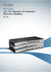
This guide provides instructions to install the D-Link Gigabit SmartPro Switch DGS-1500-20/28/28P/52, how
to use the SmartConsole Utility, and to configure Web-based Management step-by-step.
Note: The model you have purchased may
appear slightly different from the illustrations
shown in the document. Refer to the Product
Instruction and Technical Specification sections
for detailed information about your switch, its
components, network connections, and technical
specifications.
This guide is mainly divided into four parts:
1.
Hardware Installation: Step-by-step hardware installation procedures.
2.
Getting Started: A startup guide for basic switch installation and settings.
3.
Smart Console Utility: An introduction to the central management system.
4.
Configuration: Information about the function descriptions and configuration settings.
Terms/Usage
In this guide, the term “Switch” (first letter capitalized) refers to the SmartPro Switch, and “switch” (first letter
lower case) refers to other Ethernet switches. Some technologies refer to terms “switch”, “bridge” and
“switching hubs” interchangeably, and both are commonly accepted for Ethernet switches.
A NOTE indicates important information that
helps a better use of the device.
A CAUTION indicates potential property damage
or personal injury.
Copyright and Trademarks
Information in this document is subjected to change without notice.
© 2011 D-Link Corporation. All rights reserved.
Reproduction in any manner whatever without the written permission of D-Link Corporation is strictly
forbidden.
Trademarks used in this text: D-Link and the D-LINK logo are trademarks of D-Link Corporation; Microsoft
and Windows are registered trademarks of Microsoft Corporation.
Other trademarks and trade names may be used in this document to refer to either the entities claiming the
marks and names or their products. D-Link Corporation disclaims any proprietary interest in trademarks and
trade names other than its own.
1
1 Product Introduction
1
D-Link Web Smart Switch User Manual
Product Introduction
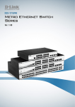
Thank you and congratulations on your purchase of D-Link SmartPro Switch Products.
D-Link's next generation SmartPro Ethernet switch series blends plug-and-play simplicity with exceptional
value and reliability for small and medium-sized business (SMB) networking. All models are housed in a new
style rack-mount metal case with easy-to-view front panel diagnostic LEDs, and provides advance features
including four 1000BASE-X SFP slots for fiber connection, network security, traffic segmentation, QoS and
versatile management.
Flexible Port Configurations. Four port densities are available for selection: 16, 24, and 48 Gigabit
Ethernet ports. Supporting auto-detection of MDI/MDIX, these switches bring inexpensive and easy Ethernet
connection to the desktops. DGS-1500 series provides 4 SFP slots, which supports 1000M fiber connections
with appropriate fiber transceivers. DGS-1500-28P provides 4 combo SFP slots, which supports both 1000M
and 100M fiber connections with appropriate fiber transceivers. The first 24 ports also support up to 15.4 or
30 watts PoE power for the connections of wireless access points, IP phones and other PoE-supported
devices, allowing them to be deployed at difficult places such as on high walls and ceilings, where AC power
outlets are not readily available.
D-Link Green Technology. D-Link Green devices are about providing eco-friendly alternatives without
compromising performance. D-Link Green Technology includes a number of innovations to reduce energy
consumption on DGS-1500 series such as reducing power when a port does not have a device attached, or
adjusting the power usage according to the Ethernet cable connected to it. For PoE model such as DGS1500-28P, D-Link Green Technology offers Time-based PoE feature to shut down per port power off working
hours.
Extensive Layer 2 Features. Implemented as complete L2 devices, these switches include functions such
as IGMP snooping, port mirroring, Spanning Tree, 802.3ad LACP, SNTP, LLDP and Loopback Detection to
enhance performance and network resiliency.
Extensive Layer 3 Features. Implemented as complete L3 devices, these switches include functions such
as IP interface, static route, IPv6 Static Route, ARP and single IP management to enhance performance and
network resiliency.
QoS. The switches supports bandwidth control and 802.1p priority queues, enabling users to run bandwidthsensitive applications such as streaming multimedia by prioritizing that traffic in network. These functions
allow switches to work seamlessly with VLAN and 802.1p traffic and IPv6 traffic class priority in the network.
Network Security. D-Link’s innovative Safeguard Engine function protects the switches against traffic
flooding caused by virus attacks. Additional features Storm Control can help to keep the network from being
overwhelmed by abnormal traffic. Port Security is another simple but useful authentication method to
maintain the network device integrity. Also supports DHCP Server Screening, SSL, SSH and Smart Binding
features.
Versatile Management. The new generation of D-Link Web Smart Switches provides growing businesses
with a simple and easy management of their network, using an intuitive SmartConsole utility or a Web-Based
management interface that allows administrators to remotely control their network down to the port level. The
SmartConsole easily allows customers to discover multiple D-Link web smart switches with the same L2
network segment connected to the user’s local PC. With this utility, users do not need to change the IP
address of the PC and provide easy initial settings of the smart switches. The switches within the same L2
network segment connected to the user’s local PC are displayed on the screen for instant access. It allows
extensive switch configuration settings, and basic configuration of discovered devices, such as a password
change or firmware upgrade.
Users can also access the switch via TELNET. Some basic tasks can be performed such as changing the
Switch IP address, resetting the settings to factory defaults, setting the administrator password, rebooting the
Switch, or upgrading the Switch firmware by using the Command Line Interface (CLI).
2
1 Product Introduction
D-Link Web Smart Switch User Manual
In addition, users can utilize the SNMP MIB (Management Information Base) to poll the switches for
information about the status, or send out traps of abnormal events. SNMP support allows users to integrate
the switches with other third-party devices for management in an SNMP-enabled environment. D-Link Web
Smart Switches also come with the D-View plug-in module that works with D-View 6 SNMP Management
Software, and provides easy-to-use graphic interface and facilitates the operation efficiency.
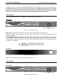
DGS-1500-20
16-Port 10/100/1000Mbps plus 4 1000Base-T/SFP ports SmartPro Switch.
Front Panel
SFP ports for optical transceivers
Figure 1.1 – DGS-1500-20 Front Panel
Power LED : The Power LED lights up when the Switch is connected to a power source.
Reset: By pressing the Reset button, the Switch will change back to the default configuration and all
changes will be lost.
Port Link/Act/Speed LED (1-16, 17F, 18F, 19F, 20F): The port LEDs indicate a network link through the
corresponding port. Blinking indicates the Switch is either sending or receiving data to the port. When the
port LED glows in amber, it indicates the port is running on 10M or 100M. When the port LED glows in green,
it is running on 1000Mbps.
CAUTION: The MiniGBIC ports should use UL
listed Optical Transceiver product, Rated Laser
Class I. 3.3Vdc
Rear Panel
Figure 1.2 – DGS-1500-20 Rear Panel
Power: The power port is where to connect the AC power cord.
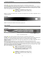
DGS-1500-28
24-Port 10/100/1000Mbps plus 4 1000Base-T/SFP ports SmartPro Switch.
Front Panel
SFP ports for optical transceivers
Figure 1.3 – DGS-1500-28 Front Panel
3
1 Product Introduction
D-Link Web Smart Switch User Manual
Power LED : The Power LED lights up when the Switch is connected to a power source.
Port Link/Act/Speed LED (1-24, 25F, 26F, 27F, 28F): The Link/Act/Speed LED flashes, which indicates a
network link through the corresponding port. Blinking indicates that the Switch is either sending or receiving
data to the port. When a port has an amber light, this indicates that the port is running on 10M or 100M.
When it has a green light it is running on 1000M.
CAUTION: The MiniGBIC ports should use UL
listed Optical Transceiver product, Rated Laser
Class I. 3.3Vdc.
Reset: By pressing the Reset button, the Switch will change back to the default configuration and all
changes will be lost.
Rear Panel
Figure 1.4 – DGS-1500-28 Rear Panel
Power: The power port is where to connect the AC power cord.
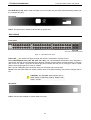
DGS-1500-28P
24-Port 10/100/1000Mbps plus 4 1000Base-T/SFP ports SmartPro PoE Switch.
Front Panel
SFP ports for optical transceivers
Figure 1.5 – DGS-1500-28P Front Panel
Power LED : The Power LED lights up when the Switch is connected to a power source.
Pwr Max: The Pwr Max LED lights up when the Switch reaches the maximum power budget defined by the
administrator via PoE System Settings page of Web GUI or the default power budget of 78 Watts.
Reset: By pressing the Reset button, the Switch will change back to the default configuration and all
changes will be lost.
Mode: By pressing the Mode button, the Port LED will switch between Link/Act and PoE modes.
Port Link/Act/Speed LED (1-24, 25F, 26F, 27F, 28F): The Link/Act/Speed LED flashes, which indicates a
network link through the corresponding port. Blinking indicates that the Switch is either sending or receiving
data to the port. When a port has an amber light, this indicates that the port is running on 10M or 100M.
When it has a green light it is running on 1000Mbps.
Fan: The Fan LED lights green when fans work well, and lights red when fans fail.
NOTE: On DGS-1500-28P, the SFP ports are
shared with normal RJ-45 ports 25 to 28. When
optical transceiver is inserted to SFP port and
link up, the RJ-45 port cannot be used.
CAUTION: The MiniGBIC ports should use UL
listed Optical Transceiver product, Rated Laser
Class I. 3.3Vdc.
4
1 Product Introduction
D-Link Web Smart Switch User Manual
Port PoE LED (1-24): When mode LED lights up in PoE mode, the port LEDs indicate powering status over
the corresponding port.
Rear Panel
Figure 1.6 – DGS-1500-28P Rear Panel
Power: The power port is where to connect the AC power cord.
DGS-1500-52
48-Port 10/100/1000Mbps plus 4 100/1000FX SFP Slot SmartPro Switch.
Front Panel
SFP ports for optical transceivers
Figure 1.7 – DGS-1500-52 Front Panel
Power LED : The Power LED lights up when the Switch is connected to a power source.
Port Link/Act/Speed LED (1-48, 49F, 50F, 51F, 52F): The Link/Act/Speed LED flashes, which indicates a
network link through the corresponding port. Blinking indicates that the Switch is either sending or receiving
data to the port. When a port has an amber light, this indicates that the port is running on 10M or 100M.
When it has a green light it is running on 1000M.
Fan: The Fan LED lights green when fans work well, and lights red when fans fail.
Reset: Press the Reset button to reset the Switch back to the default settings. All previous changes will be
lost.
CAUTION: The MiniGBIC ports should use UL
listed Optical Transceiver product, Rated Laser
Class I. 3.3Vdc.
Rear Panel
Figure 1.8 – DGS-1500-52 Rear Panel
Power: Connect the supplied AC power cable to this port.
5
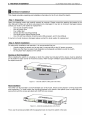
2 Hardware Installation
D-Link Web Smart Switch User Manual
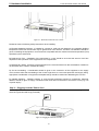
Figure 2.3 – Mount the Switch in the rack or chassis
Please be aware of following safety Instructions when installing:
A) Elevated Operating Ambient - If installed in a closed or multi-unit rack assembly, the operating ambient
temperature of the rack environment may be greater than room ambient. Therefore, consideration should be
given to installing the equipment in an environment compatible with the maximum ambient temperature (Tma)
specified by the manufacturer.
B) Reduced Air Flow - Installation of the equipment in a rack should be such that the amount of air flow
required for safe operation of the equipment is not compromised.
C) Mechanical Loading - Mounting of the equipment in the rack should be such that a hazardous condition is
not achieved due to uneven mechanical loading.
D) Circuit Overloading - Consideration should be given to the connection of the equipment to the supply
circuit, and the effect that overloading of the circuits might have on overcurrent protection and supply wiring.
Appropriate consideration of equipment nameplate ratings should be used when addressing this concern.
E) Reliable Earthing - Reliable earthing of rack-mounted equipment should be maintained. Particular
attention should be given to supply connections other than direct connections to the branch circuit (e.g. use
of power strips)."
Step 3 – Plugging in the AC Power Cord
Users may now connect the AC power cord into the rear of the switch and to an electrical outlet (preferably
one that is grounded and surge protected).
Figure 2.4 –Plugging the switch into an outlet
7
2 Hardware Installation
D-Link Web Smart Switch User Manual
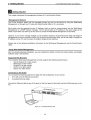
Power Failure
As a precaution, the switch should be unplugged in case of power failure. When power is resumed, plug the
switch back in.
8
3 Getting Started
D-Link Web Smart Switch User Manual
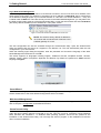
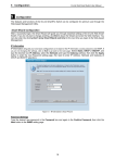
Login Web-based Management
In order to login and configure the switch via an Ethernet connection, the PC must have an IP address in the
same subnet as the switch. For example, if the switch has an IP address of 10.90.90.90, the PC should have
an IP address of 10.x.y.z (where x/y is a number between 0 ~ 254 and z is a number between 1 ~ 254), and
a subnet mask of 255.0.0.0. There are two ways to launch the Web-based Management, you may either click
the Web Access button at the top of the SmartConsole Utility or open the web browser and enter 10.90.90.90
(the factory-default IP address) in the address bar. Then press <Enter>.
Figure 3.2 –Enter the IP address 10.90.90.90 in the web browser
NOTE: The switch's factory default IP address is
10.90.90.90 with a subnet mask of 255.0.0.0 and
a default gateway of 0.0.0.0.
The web configuration can also be accessed through the SmartConsole Utility. Open the SmartConsole
Utility and double-click the switch as it appears in the Monitor List. This will automatically load the web
configuration in your web browser.
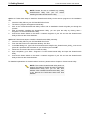
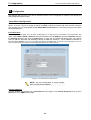
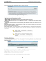
When the following logon dialog box appears, enter the password and choose the language of the Webbased Management interface then click OK.
The switch supports 10 languages including English, Traditional Chinese, Simplified Chinese, German,
Spanish, French, Italian, Portuguese, Japanese and Russian. By default, the password is admin and the
language is English.
Figure 3.3 – Logon Dialog Box
Smart Wizard
After a successful login, the Smart Wizard will guide you through essential settings of the D-Link Web Smart
Switch. Please refer to the Smart Wizard Configuration section for details.
Web-based Management
By clicking the Exit button in the Smart Wizard, you will enter the Web-based Management interface. Please
refer to Chapter 5 Configuration for detailed instructions.
SmartConsole Utility
The SmartConsole Utility included in the installation CD is a program for discovering D-Link Smart Switches
within the same network segment connected to your PC. This tool is only for computers running Windows
2000, Windows XP, Windows 7, or Windows Vista operating systems. There are two options for the
installation of the SmartConsole Utility; one is through the autorun program on the installation CD and the
other is manual installation.
10
3 Getting Started
D-Link Web Smart Switch User Manual
NOTE: Please be sure to uninstall any existing
SmartConsole Utility from your PC before
installing the latest SmartConsole Utility.
Option 1: Follow these steps to install the SmartConsole Utility via the autorun program on the installation
CD.
1.
Insert the Utility CD into your CD-Rom/DVD-Rom Drive.
2.
The autorun program will appear automatically.
3.
Click on the ”Install SmartConsole Utility” button and an installation wizard will guide you through the
process.
4.
After successfully installing the SmartConsole Utility, you can open the utility by clicking Start >
Programs > D-Link SmartConsole Utility.
5.
Connect the Smart Switch to the same L2 network segment of your PC and use the SmartConsole
Utility to discover the Smart Switches.
Option 2: Follow these steps to install the SmartConsole Utility manually.
1.
Insert the Utility CD into your CD-Rom/DVD-Rom Drive.
2.
From the Start menu on the Windows desktop, click Run.
3.
In the Run dialog box, type D:\D-Link SmartConsole Utility\D-Link_SmartConsole_Utility_v3.00.10.exe
(where D:\ represents the drive letter of your CD-Rom) and click OK.
4.
Follow the on-screen instructions to install the utility.
5.
Upon completion, go to Start > Programs > D-Link SmartConsole Utility and open the SmartConsole
Utility.
6.
Connect the Smart Switch to the same L2 network segment of your PC and use the SmartConsole
Utility to discover the Smart Switches.
For detailed explanations of SmartConsole’s functions, please refer to Chapter 4 SmartConsole Utility
NOTE: The current SmartConsole Utility does not
support IPv6 feature. Please be sure to install the
SmartConsole Utility from you PC with IPv4
address. After installed SmartConsole Utility, then
it can discover the DGS-1500 series with IPv6
address.
11
4 SmartConsole Utility
4
D-Link Web Smart Switch User Manual
SmartConsole Utility
The D-Link SmartConsole Utility allows the administrator to quickly discover all D-Link smart switches, which
are in the same domain of the PC, collect traps and log messages, and quick access to basic configurations
of the switch.
The SmartConsole Utility consists of three parts, Device Configurations at the top, Device List as the main
body, and SmartConsole Settings at the left.
Figure 4.1 – SmartConsole Utility
SmartConsole Settings
The SmartConsole Settings at the left has five icons, Utility Settings, Log, Trap, Monitor list, and About.
Utility Settings
Click this icon to launch the Utility Settings window. Refresh time refreshes the devices, which were
selected as monitored devices in the Device List. Choices include 15 secs, 30 secs, 1 mins, 2 mins, and 5
mins for selecting the monitoring time intervals. Utility Group Interval establishes the intervals (in seconds)
that the Switch will be discovered in the SmartConsole Device List.
Figure 4.2 – SmartConsole Utility Settings
NOTE: If the Group Interval is set to 0, IGMP
Snooping must be disabled in the Switch, or the
SmartPro Switch will not be discovered.
Log
Click this icon to launch the Log window. Click View Log to show the events of the SmartConsole Utility and
the device. Time indicates when the message was received, Location indicates where the message was
12
4 SmartConsole Utility
D-Link Web Smart Switch User Manual
received and IP Address denotes where it comes from. Click Refresh to redisplay all log entries, click Clear
to clear all log entries. Click Exit to exit.
Figure 4.3 – SmartConsole Log
Trap
Click this icon to launch the Trap window. Click View Trap to show the events of the SmartConsole Utility
and the device. Time indicates when the trap message was received, Location indicates where the trap
message was received, IP denotes where it comes from and Event shows the content of this trap message.
Click Refresh to redisplay all traps, click Clear to clear all entries. Click Exit to exit
Figure 4.4 – SmartConsole Trap
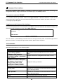
The trap icon in the SmartConsole Settings will change while receiving new trap messages. Please see
below for detailed description.
Icon
Description
No new traps
New traps was received
Monitor List
By clicking on this icon you will see below options:
13
4 SmartConsole Utility
D-Link Web Smart Switch User Manual
Figure 4.5 – SmartConsole Monitor List
Save: Records the setting of the Device List as default for the next time the SmartConsole Utility is used.
Save As: Records the setting of the Device List in an appointed filename and file path.
Restore: Manually reload a Device List setting file.
About
Click this icon to launch the SmartConsole Info window.
Figure 4.6 – SmartConsole About
Device Configuration
The Device Configuration in the SmartConsole Utility has five icons:
Device Settings
Password Settings
Firmware Upgrade
DHCP Refresh
Web Access
and the
,
,
device buttons for the Device List.
Device Settings
Select a switch from the Device List. Click on this icon to launch the Device Settings window. Here you can
configure the Product Name, MAC Address, IPv4 Address, Subnet Mask, Gateway, System Name, Location,
Trap IP, Group Interval, and DHCP Client Setting of the Switch.
To apply the configuration, insert the correct device password in the Confirm Password box and then click
OK.
14
4 SmartConsole Utility
D-Link Web Smart Switch User Manual
Figure 4.7 – SmartConsole Device Settings
Password Settings
Select a switch from the Device List. Click on this icon to launch the Device Password Manager window.
Here you can enter a new password and confirm it.
Figure 4.8 – SmartConsole Password Settings
Firmware Upgrade
Select one or many switches of the same model name from the Device List. Click on this icon to launch the
Firmware Upgrade window. Specify the Firmware Path (or Browse for one) that you are going to use. Input
the correct password of the device, and then click Upgrade. The state will show "OK" after completion, or
“Fail” if the firmware upgrade fails or cannot be completed for any reason.
15
4 SmartConsole Utility
D-Link Web Smart Switch User Manual
Figure 4.9 – Firmware Upgrade
CAUTION: Do not disconnect the PC or remove
the power cord from the device until the upgrade
completes. The software may be corrupted
because of the incomplete firmware upgrade.
DHCP Refresh:
If a DHCP-client enabled switch in the Device List shows the default IP is still used, it means the device did
not receive an IPv4 address from the DHCP server successfully. Select that switch and click the DHCP
refresh icon. Enter the correct Device Password and then click OK. The device will renew the IPv4 address
from the DHCP server.
Figure 4.10 – DHCP Refresh
Web Access
Select a switch from the Device List. Click this icon to launch your Internet browser (eg. The Internet
Explorer). Here you can configure the Switch through the Web-based Management utility. You may also get
into the Web-based Management by double-clicking the device in the device list.
Add(+), Delete(-) and Discover the device
Click the Discovery button to display all of the Web-Smart devices located in the same domain with the
management PC.
Click the + and insert a device IP address to add a device into the Discover List, or select a device and click
the – button to remove it.
16
4 SmartConsole Utility
D-Link Web Smart Switch User Manual
Figure 4.11 – SmartConsole Add device
Figure 4.12 – SmartConsole Delete device
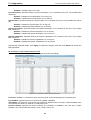
Device List
This list displays all discovered Web-Smart devices on the network.
Figure 4.13 – SmartConsole Device List
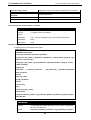
Definitions of the Device List features:
Select: Click the Select to choose a switch for configuration settings.
Monitor: Click the Monitor button and the SmartConsole will collect the trap and log data from the device.
in the monitor means the device was discovered by SmartConsole. Click the icon to have the
The
device to continue updating the information, such as system log or trap to the SmartConsole Utility. The icon
. When the device was detected as not reachable, the icon will change to
will appear
if the power or the cable of this device is disconnected.
Product Name: Displays the device product name.
IP Address: Displays the current IP addresses of devices.
Subnet Mask: Displays the Subnet Mask setting of the device.
Gateway: Displays the Gateway setting of the device.
MAC Address: Displays the device MAC Addresses.
Firmware version: Displays the current Firmware version of this device.
System Name: Displays the appointed device system name.
Location: Displays the location of the appointed device.
SNMP: Displays the SNMP status of the device.
Trap IP: Displays the IP address of the host where the Trap information will be sent.
DHCP: Specify if the device gets the IP address from a DHCP server.
17
. Please check
4 SmartConsole Utility
D-Link Web Smart Switch User Manual
Group Interval: Displays the intervals (in seconds) that the Switch will be discovered in the SmartConsole
Device List.
NOTE: If the devices are marked red in the device
list, it means that a firmware upgrade is required
again.
NOTE: If the IP address of device is showed with
IPv6 address, then it can not be configured with
Smartconsole Utility. The user needs to double
click the selected device and login the web for
configuration.
18
5 Configuration
5
D-Link Web Smart Switch User Manual
Configuration
The features and functions of the D-Link SmartPro Switch can be configured for optimum use through the
Web-based Management Utility.
Smart Wizard Configuration
After a successful login, the Smart Wizard will guide you through essential settings of the D-Link Web Smart
Switch. If you do not plan to change anything, click Exit to leave the Wizard and enter the Web Interface.
You can also skip it by clicking Don’t show Smart Wizard next time for the next time you logon to the Webbased Management.
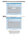
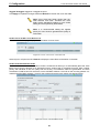
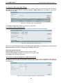
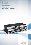
IPv4 Information
IPv4 Information will guide you to do basic configurations on 3 steps for the IP Information, access password, and
SNMP. Select Static, DHCP or BOOTP, and type the desired new IP Address, select the Netmask and type
the Gateway address, then click the Apply button to enter the next Password setting page. (No need to
enter IP Address, Netmask and Gateway of DHCP and BOOTP selection.) The IP address is allowed for
IPv4 and IPv6 address. If you are not changing the settings, click Exit button to go back to the main page. Or you can
click on Ignore the wizard next time to skip wizard setting when the switch boots up.
Figure 5.1 – IPv4 Information in Smart Wizard
NOTE: The IPv4 Information of Smart Wizard
does not support IPv6 address.
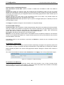
Password Settings
Type the desired new password in the Password box and again in the Confirm Password, then click the
Next button to the SNMP setting page.
19
5 Configuration
D-Link Web Smart Switch User Manual
Figure 5.2 – Password setting in Smart Wizard
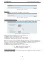
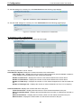
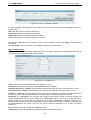
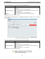
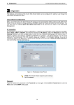
SNMP Settings
The SNMP Setting allows you to quickly enable/disable the SNMP function. The default SNMP Setting is
Disabled. Click Enabled and then click Apply to make it effective.
Figure 5.3 – SNMP Setting in Smart Wizard
NOTE: Changing the system IP address will
disconnect you from the current connection.
Please enter the correct IP address in the Web
browser again and make sure your PC is in the
same subnet with the switch. See Login Webbased Management for a detailed description.
20
5 Configuration
D-Link Web Smart Switch User Manual
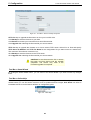
If you want to change the IP settings, click OK and start a new web browser.
Figure 9 – Confirm the changes of IP address in Smart Wizard
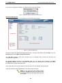
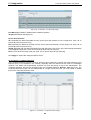
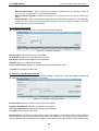
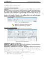
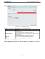
Web-based Management
After clicking the Exit button in Smart Wizard you will see the screen below:
Figure 5.4 – Web-based Management
The above image is the Web-based Management screen. The three main areas are the Tool Bar on top, the
Function Tree, and the Main Configuration Screen.
The Tool Bar provides a quick and convenient way for essential utility functions like firmware and
configuration management.
By choosing different functions in the Function Tree, you can change all the settings in the Main
Configuration Screen. The main configuration screen will show the current status of your Switch by clicking
the model name on top of the function tree.
At the upper right corner of the screen the username and current IP address will be displayed.
Under the username is the Logout button. Click this to end this session.
NOTE: If you close the web browser without
clicking the Logout button first, then it will be seen
as an abnormal exit and the login session will still
be occupied.
21
5 Configuration
D-Link Web Smart Switch User Manual
Finally, by clicking on the D-Link logo at the upper-left corner of the screen you will be redirected to the local
D-Link website.
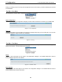
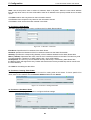
Tool Bar > Save Menu
The Save Menu provides Save Configuration and Save Log functions.
Figure 5.5 – Save Menu
Save Configuration
Select to save the entire configuration changes you have made to the device to switch’s non-volatile RAM.
Figure 5.6 – Save Configuration
Save Log
Save the log entries to your local drive and a pop-up message will prompt you for the file path. You can view
or edit the log file by using text editor (e.g. Notepad).
Figure 5.7 – Save Log
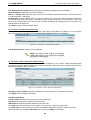
Tool Bar > Tool Menu
The Tool Menu offers global function controls such as Reset, Reset System, Reboot Device, Configuration
Backup and Restore, Firmware Backup and Upgrade.
Figure 5.8 – Tool Menu
Reset
Provide a safe reset option for the Switch. All configuration settings in non-volatile RAM will be reset to
factory default except for the IP address.
Figure 5.9 – Tool Menu > Reset
Reset System
Provide another safe reset option for the Switch. All configuration settings in non-volatile RAM will reset to
factory default and the Switch will reboot.
22
5 Configuration
D-Link Web Smart Switch User Manual
Figure 5.10 – Tool Menu > Reset System
Reboot Device
Provide a safe way to reboot the system. Click Reboot to restart the switch.
Figure 5.11 – Tool Menu > Reboot Device
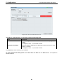
Configuration Backup and Restore
Allow the current configuration settings to be saved to a file (not including the password), and if necessary,
you can restore configuration settings from this file. Two methods can be selected: HTTP or TFTP.
Figure 5.12 – Tool Menu > Configure Backup and Restore
HTTP: Backup or restore the configuration file to or from your local drive.
Click Backup to save the current settings to your disk.
Click Browse to browse your inventories for a saved backup settings file.
Click Restore after selecting the backup settings file you want to restore.
TFTP: TFTP (Trivial File Transfer Protocol) is a file transfer protocol that allows you to transfer files to a
remote TFTP server. Select IPv4 or IPv6 and specify TFTP Server IP Address and TFTP File Name for the
configuration file you want to save to / restore from. The maximum Telnet Server connection is 4.
Click Backup to save the current settings to the TFTP server.
Click Restore after selecting the backup settings file you want to restore.
Note: Switch will reboot after restore, and
all current configurations will be lost
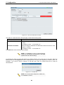
Firmware Backup and Upgrade
Allow for the firmware to be saved, or for an existing firmware file to be uploaded to the Switch. Two methods
can be selected: HTTP or TFTP.
23
5 Configuration
D-Link Web Smart Switch User Manual
Figure 5.13 – Tool Menu > Firmware Backup and Upload
HTTP: Backup or upgrade the firmware to or from your local PC drive.
Click Backup to save the firmware to your disk.
Click Browse to browse your inventories for a saved firmware file.
Click Upgrade after selecting the firmware file you want to restore.
TFTP: Backup or upgrade the firmware to or from a remote TFTP server. Select IPv4 or IPv6 and specify
TFTP Server IP Address and TFTP File Name for the configuration file you want to save to / restore from.
The maximum Telnet Server connection is 4.
Click Backup to save the firmware to the TFTP server.
Click Upgrade after selecting the firmware file you want to restore.
CAUTION: Do not disconnect the PC or remove
the power cord from device until the upgrade
completes. The Switch may crash if the
Firmware upgrade is incomplete.
Tool Bar > Smart Wizard
By clicking the Smart Wizard button, you can return to the Smart Wizard if you wish to make any changes
there.
Tool Bar > Online Help
The Online Help provides two ways of online support: Online Support Site will lead you to the D-Link
website where you can find online resources such as updated firmware images; User Guide can offer an
immediate reference for the feature definition or configuration guide.
Figure 5.14 – Online Help
24
5 Configuration
D-Link Web Smart Switch User Manual
Figure 5.15 – User Guide Micro Site
25
5 Configuration
D-Link Web Smart Switch User Manual
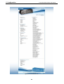
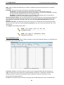
Function Tree
All configuration options on the switch are accessed through the Setup menu on the left side of the screen.
Click on the setup item that you want to configure. The following sections provide more detailed description
of each feature and function.
Figure 5.16 –Function Tree
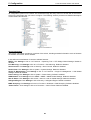
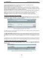
Device Information
The Device Information provides an overview of the switch, including essential information such as firmware
& hardware information, and IP address.
It also offers an overall status of common software features:
MSTP: Click Settings to link to L2 Functions > Spanning Tree > STP Bridge Global Settings. Default is
disabled.
Port Mirroring: Click Settings to link to L2 Functions > Port Mirroring. Default is disabled.
Storm Control: Click Settings to link to Security > Storm Control. Default is disabled.
DHCP Client: Click Settings to link to System > System Settings. Default is disabled.
Single IP Management: Click Settings to link to L3 Functions > Single IP Management > SIM Global
Settings. Default is disabled.
Power Saving: Click Settings to link to System > Power Saving. Default is enabled.
SNMP Status: Click Settings to link to SNMP > SNMP > SNMP Global Settings. Default is disabled.
802.1X Status: Click Settings to link to AAA > 802.1X > 802.1X Global Settings. Default is disabled.
Safeguard Engine: Click Settings to link to Security > Safeguard Engine. Default is enabled.
IGMP Snooping: Click Settings to link to L2 Functions > Multicast > IGMP Snooping. Default is disabled.
Jumbo Frame: Click Settings to link to L2 Functions > Jumbo Frame. Default is disabled.
26
5 Configuration
D-Link Web Smart Switch User Manual
Figure 5.17 – Device Information
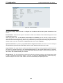
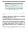
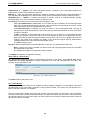
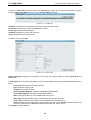
System > System Settings
The System Setting allows the user to configure the IP address and the basic system information of the
Switch.
IP Information: There are two ways for the switch to obtain an IP address: Static and DHCP (Dynamic Host
Configuration Protocol).
When using static mode, the IP Address, Subnet Mask and Gateway can be manually configured. When
using DHCP mode, the Switch will first look for a DHCP server to provide it with an IP address (including
network mask and default gateway) before using the default or previously entered settings. By default the IP
setting is static mode with IP address is 10.90.90.90 and subnet mask is 255.0.0.0.
System Information: By entering a System Name and System Location, the device can more easily be
recognized through the SmartConsole Utility and from other Web-Smart devices on the LAN.
Login Timeout: The Login Timeout controls the idle time-out period for security purposes, and when there is
no action for a specific time span in the Web-based Management. If the current session times out (expires),
the user is required a re-login before using the Web-based Management again. Selective range is from 3 to
30 minutes, and the default setting is 5 minutes.
Group Interval: The D-Link Web Smart Switch will routinely send report packets to the SmartConsole Utility
in order to maintain the information integrity. The user can adjust the Group Interval to optimal frequency.
Selective range is from 120 to 1225 seconds, and 0 means disabling the reporting function.
27
5 Configuration
D-Link Web Smart Switch User Manual
Figure 5.18 – System > System Settings
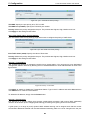
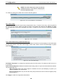
System > Password
The Password page allows user to change the login password of the device.
Figure 5.19 – System > Password
To set the Password, set the following parameters and click Apply:
Old Password: If a password was previously configured for this entry, enter it here in order to change it to a
new password.
New Password: Enter the new password that you wish to set on the Switch to authenticate users attempting
to access Administrator Level privileges on the Switch. The user may set a password of up to 20 characters.
Confirm Password: Confirm the new password entered above. Entering a different password here from the
one set in the New Local Enabled field will result in a fail message.
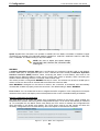
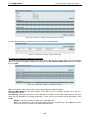
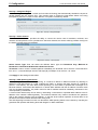
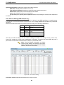
System > Port Settings
In the Port Setting page, the status of all ports can be monitored and adjusted for optimum configuration. By
selecting a range of ports (From Port and To Port), the Speed can be set for all selected ports by clicking
Apply. Press the Refresh button to view the latest information.
28
5 Configuration
D-Link Web Smart Switch User Manual
Figure 5.20 – System > Port Settings
Speed: Gigabit Fiber connections can operate in 1000M Full Force Mode, Auto Mode or Disabled. Copper
connections can operate in Forced Mode settings (1000M Full, 100M Full, 100M Half, 10M Full, 10M Half),
Auto, or Disabled. The default setting for all ports is Auto.
NOTE: Be sure to adjust port speed settings
appropriately after changing the connected cable
media types.
MDI/MDIX:
A medium dependent interface (MDI) port is an Ethernet port connection typically used on the Network
Interface Card (NIC) or Integrated NIC port on a PC. Switches and hubs usually use Medium dependent
interface crossover (MDIX) interface. When connecting the Switch to end stations, user have to use
straight through Ethernet cables to make sure the Tx/Rx pairs match up properly. When connecting the
Switch to other networking devices, a crossover cable must be used.
This switch provides a configurable MDI/MDIX function for users. The switches can be set as an MDI port in
order to connect to other hubs or switches without an Ethernet crossover cable.
Auto MDI/MDIX is designed on the switch to detect if the connection is backwards, and automatically
chooses MDI or MDIX to properly match the connection. The default setting is “Auto” MDI/MDIX.
Flow Control: You can enable this function to mitigate the traffic congestion. Ports configured for full-duplex
use 802.3x flow control, half-duplex ports use backpressure flow control. The default setting is Disabled.
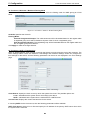
System > DHCP Auto Configuration
This page allows you to enable the DHCP Auto Configuration feature on the Switch. When enabled, the
Switch becomes a DHCP client and gets the configuration file from a TFTP server automatically on next boot
up. To accomplish this, the DHCP server must deliver the TFTP server IP address and configuration file
name information in the DHCP reply packet. The TFTP server must be up and running and store the
necessary configuration file in its base directory when the request is received from the Switch.
Figure 5.21 – System > DHCP Auto Configuration
29
5 Configuration
D-Link Web Smart Switch User Manual
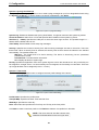
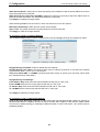
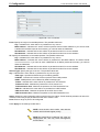
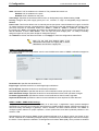
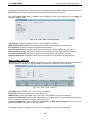
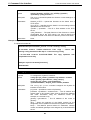
System > SysLog Host Settings
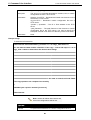
The SysLog Host Settings page allows user to send Syslog messages to up to four designated servers using
the System Log Server. To set the System Log Server configuration, click Apply.
Figure 5.22 – System > SysLog Host Settings
System Log: Enabled or Disabled the SysLog Host feature. It supports maximum 500 system log entries.
Server IP Address: Select IPv4 or IPv6 and specifies the IP address of the system log server.
UDP Port (1 - 65535): Specifies the UDP port to which the server logs are sent. The possible range is 1 –
65535, and the default value is 514.
Time Stamp: Select Enable to time stamp log messages.
Severity: Specifies the minimum severity from which warning messages are sent to the server. There are
three levels. When a severity level is selected, all severity level choices above the selection are selected
automatically. The possible levels are:
Warning - The lowest level of a device warning. The device is functioning, but an operational
problem has occurred.
Informational - Provides device information.
All - Displays all levels of system logs.
Facility: Specifies an application from which system logs are sent to the remote server. Only one facility can
be assigned to a single server. If a second facility level is assigned, the first facility is overwritten. There are
up to eight facilities can be assigned (Local 0 ~ Local 7).
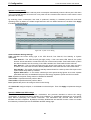
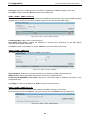
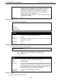
System > Time Profile
The Time Profile page allows users to configure the time profile settings of the device.
Figure 5.23 – System > Time Profile Settings
Profile Name: Specifies the profile name.
Time(HH MM): Specifies the Start Time and End Time.
Weekdays: Specifies the work day.
Date: Select Date and specifies the From Day and To Day of the time profile.
Click Add to create a new time profile or click Delete to delete a time profile from the table.
NOTE: The time must be set after current time,
otherwise it will take effect on the next cycle time.
30
5 Configuration
D-Link Web Smart Switch User Manual
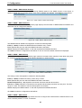
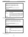
System > Power Saving
The Power Saving mode feature reduces power consumption automatically when the RJ-45 port is link down
or the connected devices are turned off. Less power will be consumed also when the short cable is used
(less than 20 meters).
By reducing power consumption, less heat is produced, resulting in extended product life and lower
operating costs. By default, the Cable Length Detection and Link Status Detection are enabled. Click Apply
to make the change effective.
Figure 5.24 – System > Power Saving
Advanced Power Saving Settings:
Type: Specifies the Power Saving type to be LED Shut-off, Port Shut-off, Port Standby or System
Hibernation.
LED Shut-off - The LED Shut-off gets high priority. If the user select LED Shut-off, the profile
function will not take effect. It means the LED can not be turned on after Time Profile time’s up when
the state is disabled. On the contrary, if the LED is enabled, the Time Profile function will work.
Port Shut-off - The Port Shut-off state has high priority (the priority rule is the same as LED.)
Therefore, if the Port Shut-off sate is already disabled the Time Profile function will not take effect.
Port Standby - The system changes to standby state and wait for a wake up event. Each port on the
system enters sleep state by schedule.
System Hibernation - In this mode, switches get most power-saving figures since main chipsets
(both MAC and PHY) are disabled for all ports, and energy required to power the CPU is minimal.
State: Specifies the power saving state to be Enabled or Disabled.
Time Profile 1: Specifies the time profile or None.
Time Profile 2: Specifies the time profile or None.
Port: Specifies the ports to be configure of the Power Saving.
Click Select All configure all ports, or click Clear to uncheck all port. Then click Apply to implement changes
made.
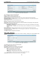
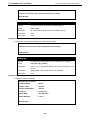
System > IEEE802.3az EEE settings
The IEEE 802.3 EEE standard defines mechanisms and protocols intended to reduce the energy
consumption of network links during periods of low utilization, by transitioning interfaces into a low-power
state without interrupting the network connection. The transmitted and received sides should be
IEEE802.3az EEE compliance. By default, the switch disabled the 802.3az EEE function. Users can enable
this feature by individual port via the IEEE802.3az EEE setting page.
31
5 Configuration
D-Link Web Smart Switch User Manual
Figure 5.25 – System > IEEE802.3az EEE settings
From Port / To Port: A consecutive group of ports may be configured starting with the selected port.
State: Enabled or Disabled the IEEE802.3az EEE for the specified ports. By default, all ports are disabled.
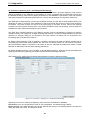
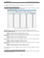
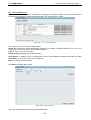
VLAN > 802.1Q VLAN
A VLAN is a group of ports that can be anywhere in the network, but communicate as though they were in
the same area.
VLANs can be easily organized to reflect department groups (such as R&D, Marketing), usage groups (such
as e-mail), or multicast groups (multimedia applications such as video conferencing), and therefore help to
simplify network management by allowing users to move devices to a new VLAN without having to change
any physical connections.
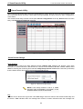
The IEEE 802.1Q VLAN Configuration page provides powerful VID management functions. The original
settings have the VID as 1, no default name, and all ports as “Untagged”
Delete: Click to delete the VLAN group.
Add: Click to create a new VID group, assigning ports from 01 to 28 as Untag, Tag, or Not Member. A port
can be untagged in only one VID. To save the VID group, click Apply.
You may change the name accordingly to the desired groups, such as R&D, Marketing, email, etc.
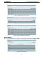
Figure 5.26 – VLAN > 802.1Q VLAN
32
5 Configuration
D-Link Web Smart Switch User Manual
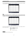
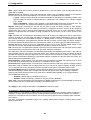
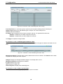
Figure 5.27 – Configuration > 802.1Q VLAN > Add VID
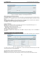
Figure 5.28 – Configuration > 802.1Q VLAN > Example VIDs
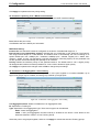
Figure 5.29 – Configuration > 802.1Q VLAN > VID Assignments
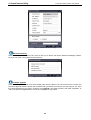
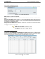
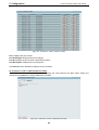
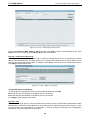
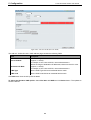
VLAN > VLAN Status
The VLAN Status page is for user to search the VLAN which has already existed by VLAN ID or VLAN
Name.
Figure 5.30 – VLAN > VLAN Status
33
5 Configuration
D-Link Web Smart Switch User Manual
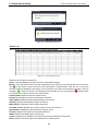
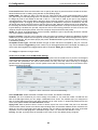
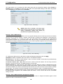
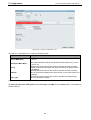
VLAN > GVRP > GVRP Global Settings
The GVRP Global Settings page allows user to configure the GARP timer values for application join, leave,
and leave_all GARP timer values.
Figure 5.31 – VLAN > GVRP > GVRP Global Settings
GVRP: Disabled or Enabled the GVRP status.
Join Time (100-100000): Indicates the time in milliseconds that PDUs are transmitted. The default value is
200ms.
Leave Time (100-100000): Indicates the amount of time in milliseconds that the device waits before leaving
its GARP state. The leave time is activated by a leave all time message sent/received, and cancelled by the
Join message. The default value is 600ms.
Leave_All Time (100-100000): Used to confirm the port within the VLAN. The time in milliseconds between
messages sent. The default value is 10000ms.
Click Apply to implement changes made.
NOTE: Leave time must be greater than or equal
to three times the join time.
Leave_all time must be greater than the
leave time.
VLAN > GVRP > GVRP Port Settings
The GVRP Port Settings page allows user to determine whether the Switch will share its VLAN configuration
information with other GARP VLAN Registration Protocol (GVRP) enabled switches. In addition, Ingress
Checking can be used to limit traffic by filtering incoming packets whose PVID does not match the PVID of
the port. Results can be seen in the table under the configuration settings, as seen below.
Figure 5.32 – VLAN > GVRP > GVRP Port Settings
34
5 Configuration
D-Link Web Smart Switch User Manual
From Port/To Port: These two fields allow user to specify the range of ports that will be included in the Portbased VLAN that user is creating using the 802.1Q Port Settings page.
PVID(1-4094): The read-only field in the 802.1Q Port Table shows the current PVID assignment for each
port, which may be manually assigned to a VLAN when created in the Settings table. The Switch's default is
to assign all ports to the default VLAN with a VID of 1. The PVID is used by the port to tag outgoing,
untagged packets, and to make filtering decisions about incoming packets. If the port is specified to accept
only tagged frames - as tagging, and an untagged packet is forwarded to the port for transmission, the port
will add an 802.1Q tag using the PVID to write the VID in the tag. When the packet arrives at its destination,
the receiving device will use the PVID to make VLAN forwarding decisions. If the port receives a packet, and
Ingress filtering is enabled, the port will compare the VID of the incoming packet to its PVID. If the two are
unequal, the port will drop the packet. If the two are equal, the port will receive the packet.
GVRP: The Group VLAN Registration Protocol (GVRP) enables the port to dynamically become a member
of a VLAN. GVRP is Disabled by default.
Ingress Checking: This field can be toggled using the space bar between Enabled and Disabled. Enabled
enables the port to compare the VID tag of an incoming packet with the PVID number assigned to the port. If
the two are different, the port filters (drops) the packet. Disabled disables ingress filtering. Ingress Checking
is Disabled by default.
Acceptable Frame Type: This field denotes the type of frame that will be accepted by the port. The user
may choose between Tagged Only, which means only VLAN tagged frames will be accepted, and Admit_All,
which mean both tagged and untagged frames will be accepted. Admit_All is enabled by default.
Click Apply to implement changes made.
VLAN > Voice VLAN > Voice VLAN Global Settings
Voice VLAN is a feature that allows you to automatically place the voice traffic from IP phone to an assigned
VLAN to enhance the VoIP service. With a higher priority and individual VLAN, the quality and the security of
VoIP traffic are guaranteed. The Voice VLAN function will only insert the Voice VLAN tag to untagged
packets under corresponding ports. If a VoIP packet comes with a VLAN tag, the Voice VLAN function won’t
replace the original VLAN tag.
Figure 5.33 – VLAN > Voice VLAN > Voice VLAN Global Settings
Voice VLAN State: Select to Enable or Disable Voice VLAN. The default is Disabled.
VLAN ID: The ID of VLAN that you want to assign voice traffic to. You must first create a VLAN from the
802.1Q VLAN page before you can assign a dedicated Voice VLAN. The member port you configured in
802.1Q VLAN setting page will be the static member port of voice VLAN. To dynamically add ports into the
voice VLAN, please enable the Auto Detection function
Aging Time: Enter a period of time in hours to remove a port from voice VLAN if the port is an automatic
VLAN member. When the last voice device stops sending traffic and the MAC address of this voice device is
aged out, the voice VLAN aging timer will be started. The port will be removed from the voice VLAN after
expiration of voice VLAN aging timer. Selectable range is from 1 to 120 hours and default is 1 hour.
Priority: The 802.1p priority levels of the traffic in the Voice VLAN. The default priority is highest.
35
5 Configuration
D-Link Web Smart Switch User Manual
Voice VLAN OUI Settings: this allows the user to configure the user-defined voice traffic’s OUI. An
Organizationally Unique Identifier (OUI) is the first three bytes of the MAC address. This identifier uniquely
identifies a vendor, manufacturer, or other organization.
Default OUI: Pre-defined OUI values, including brand names of 3COM, Cisco, Veritel, Pingtel, Siemens,
NEC/Philips, Huawei3COM, and Avaya.
User defined OUI: You can manually create a Telephony OUI with a description. The maximum number of
user defined OUIs is 10. It will occupy one ACL rule when selecting user defined OUI by default, and to
configure one user-defined OUI will take extra one ACL rule. System will auto generate an ACL profile
(Profile ID: 51) for all the Voice VLAN rules.
There are some pre-defined OUIs and when the user configures personal OUI, these pre-defined OUIs must
be avoided. Below are the pre-defined voice traffic’s OUI:
OUI
Vendor
Mnemonic Name
00:E0:BB
3COM
3com
00:03:6B
Cisco
cisco
00:E0:75
Veritel
veritel
00:D0:1E
Pingtel
pingtel
00:01:E3
Siemens
siemens
00:60:B9
NEC/ Philips
nec&philips
00:0F:E2
Huawei-3COM
huawei&3com
00:09:6E
Avaya
avaya
Select the OUI and press Add to the lower table to complete the Auto Voice VLAN setting.
Note: The default OUI for 3COM, Cisco, Veritel,
Pingtel, Siemens, NEC/Philips, Huawei3COM,
and Avaya is not common for all of their VoIP
devices.
VLAN > Voice VLAN > Voice VLAN Port Settings
The Voice VLAN Port Settings page allows users to automatically place the voice traffic from IP phone to an
assigned VLAN to enhance the VoIP service. With a higher priority and individual VLAN, the quality and the
security of VoIP traffic are guaranteed.
Figure 5.34 – VLAN > Voice VLAN > Voice VLAN Port Settings
From Port / To Port: A consecutive group of ports may be configured starting with the selected port.
Auto Detection: Switch will add ports to the voice VLAN automatically if it detects the device OUI matches
the Telephony OUI configured in Voice VLAN OUI Setting page. Use the drop-down menu to enable or
disable the OUI auto detection function. The default is Disabled
36
5 Configuration
D-Link Web Smart Switch User Manual
Tagged / Untagged: tagged or untagged the ports.
Click Apply to implement changes made and Refresh to refresh the voice vlan table.
Note: Voice VLAN has higher priority than any
other features even QoS. Therefore the voice
traffic will be operated according to Voice VLAN
setting and not impacted by QoS feature.
Note: It is recommended setting the highest
priority for Voice VLAN to guarantee the quality of
VoIP traffic.
VLAN > Voice VLAN > Voice Device List
The Voice Device List page displays the information of Voice VLAN.
Figure 5.35 – VLAN > Voice VLAN > Voice Device List
Select a port or all ports and click Search to display the Voice Device information in the table.
VLAN > Auto Surveillance VLAN
Similar as Voice VLAN, Auto Surveillance VLAN is a feature that allows you to automatically place the video
traffic from D-Link IP cameras to an assigned VLAN to enhance the IP surveillance service. With a higher
priority and individual VLAN, the quality and the security of surveillance traffic are guaranteed. The Auto
Surveillance VLAN function will check the source OUI/MAC address / VLAN ID on the incoming packets. If it
matches specified MAC address / VLAN ID, the packets will pass through switch with desired priority.
Figure 5.36 – VLAN > Auto Surveillance VLAN
37
5 Configuration
D-Link Web Smart Switch User Manual
Auto Surveillance VLAN Global Settings:
Auto Surveillance VLAN State: Select to enable or disable Auto Surveillance VLAN. The default is
Disabled.
VLAN ID: By default, the VLAN ID 4094 was created as Auto Surveillance VLAN. You also can create
another Auto Surveillance VLAN by selecting a VLAN ID that you have created a VLAN from the 802.1Q
VLAN page. The member port you configured in 802.1Q VLAN setting page will be the static member port of
Auto Surveillance VLAN.
Priority: Specifies the priority level of Auto Surveillance VLAN on the Switch. The possible values are
Highest, High, Medium and Low. The default priority is High.
Tagged Uplink/Downlink Port: Specifies the port or ports to be tagged uplink port or downlink port for the
Auto Surveillance VLAN.
Click Apply to implement changes of Auto Surveillance VLAN global settings.
User-defined MAC Settings:
Component Type: Auto Surveillance VLAN will automatically detect D-Link Surveillance Devices by default.
There are another five surveillance components that could be configured to be auto-detected by the Auto
Surveillance VLAN. These five components are Video Management Server (VMS), VMS Client/Remote
viewer, Video Encoder, Network Storage and Other IP Surveillance Devices.
Description: Specifies the description for the component type.
MAC/OUI: You can manually create an MAC or OUI address for the surveillance component. The maximum
number of user defined MAC address is 5. System will auto generate an ACL profile (Profile ID: 56) for all the
Auto Surveillance VLAN rules.
Click Add to create a new surveillance component and Refresh to refresh the Auto Surveillance VLAN
summary table.
L2 Functions > Jumbo Frame
Jumbo Frame support is designed to enhance Ethernet networking throughput and significantly reduce the
CPU utilization of large file transfers like large multimedia files or large data files by enabling more efficient
larger payloads per packet. The Jumbo Frame page allows network managers to enable Jumbo Frames on
the device.
The Jumbo Frame default is disabled, Select Enabled then click Apply to turn on the jumbo frame support.
Figure 5.37 – L2 Functions > Jumbo Frame Settings
L2 Functions > Port Mirroring
Port Mirroring is a method of monitoring network traffic that forwards a copy of each incoming and/or
outgoing packet from one port of the Switch to another port where the packet can be studied. This enables
network managers to better monitor network performances.
38
5 Configuration
D-Link Web Smart Switch User Manual
Figure 5.38 – L2 Functions > Port Mirroring Settings
Port Mirroring: Enables or disables the Port Mirroring status.
Target Port: Defines the target port.
Source Port Selection:
TX: Duplicates the data transmitted from the source port and forwards it to the Target Port. Click “all” to
include all ports into port mirroring.
RX: Duplicates the data that received from the source port and forwards it to the Target Port. Click “all” to
include all ports into port mirroring.
TX/RX: Duplicate both the data transmitted from and data sent to the source port, and forwards all the data
to the assigned Target Port. Click “all” to include all ports into port mirroring.
None: Turns off the mirroring of the port. Click “all” to remove all ports from mirroring.
Click Apply to capture the configured Source Ports.
L2 Functions > Loopback Detection
The Loopback Detection function is used to detect the loop created by a specific port while Spanning Tree
Protocol (STP) is not enabled in the network, especially when the down links are hubs or unmanaged
switches. The Switch will automatically shutdown the port and sends a log to the administrator. The
Loopback Detection port will be unlocked when the Loopback Detection Recover Time times out. The
Loopback Detection function can be implemented on a range of ports at a time. You may enable or disable
this function using the pull-down menu.
Figure 5.39 – L2 Functions > Loopback Detection Settings
39
5 Configuration
D-Link Web Smart Switch User Manual
Loopback Detection State: Enable or disable loopback detection. The default is Disabled.
Mode: Specifies Port-based or VLAN-based mode.
Interval (1-32767): Set a Loop detection Interval between 1 and 32767 seconds. The default is 2 seconds.
Recover Time (0 or 60-1000000): Time allowed (in seconds) for recovery when a Loopback is detected.
The Loop Detection Recover Time can be set at 0 seconds, or 60 to 1000000 seconds. Entering 0 will
disable the Loop Detection Recover Time. The default is 60 seconds.
From Port: The beginning of a consecutive group of ports may be configured starting with the selected port.
To Port: The ending of a consecutive group of ports may be configured starting with the selected port.
State: Use the drop-down menu to toggle between Enabled and Disabled. Default is Disabled.
Click Apply to implement changes made or click Refresh to refresh the Loopback Detection table.
L2 Functions > MAC Address Table > Static MAC
This feature provides two distinct functions. The Disable Auto Learning table allows turning off the function
of learning MAC address automatically, if a port isn't specified as an uplink port (for example, connects to a
DHCP Server or Gateway). By default, this feature is Disabled.
Figure 5.40 – L2 Functions > MAC Address Table > Static MAC
To initiate the removal of auto-learning for any of the uplink ports, enable this feature, and then select the
port(s) for auto learning to be disabled.
The Static MAC Address Lists table displays the static MAC addresses connected, as well as the VID.
Click Add to add a new MAC address, you also need to select the assigned Port number. Enter both the
Mac Address and VID, and then Click Add. Click Delete to remove one entry or click Delete all to clear the
list.
By disabling Auto Learning capability and specifying the static MAC addresses, the network is protected from
potential threats like hackers, because traffic from illegal MAC addresses will not be forwarded by the Switch.
L2 Functions > MAC Address Table > Dynamic Forwarding Table
For each port, this table displays the MAC address learned by the Switch. To add a MAC address to the
Static Mac Address List, click the Add to Static MAC checkbox, and then click Apply associated with the
identified address.
Figure 5.41 – L2 Functions > MAC Address Table > Dynamic Forwarding Table
40
5 Configuration
D-Link Web Smart Switch User Manual
L2 Functions > Spanning Tree > STP Bridge Global Settings
The Switch implements three versions of the Spanning Tree Protocol, the Rapid Spanning Tree Protocol
(RSTP) as defined by the IEEE 802.1w specification, a version compatible with the IEEE 802.1D STP and
the Multiple Spanning Tree Protocol (MSTP) as defined by the IEEE802.1 specification. RSTP can operate
with legacy equipment implementing IEEE 802.1D, however the advantages of using RSTP will be lost.
The IEEE 802.1w Rapid Spanning Tree Protocol (RSTP) evolved from the 802.1D STP standard. RSTP was
developed in order to overcome some limitations of STP that impede the function of some recent switching
innovations. The basic function and much of the terminology is the same as STP. Most of the settings
configured for STP are also used for RSTP. This section introduces some new Spanning Tree concepts and
illustrates the main differences between the two protocols.
The IEEE 802.1 Multiple Spanning Tree (MSTP) provides various load balancing scenarios by allowing
multiple VLANs to be mapped to a single spanning tree instance, providing multiple pathways across the
network. For example, while port A is blocked in one STP instance, the same port can be placed in the
Forwarding state in another STP instance.
By default, Rapid Spanning Tree is disabled. If enabled, the Switch will listen for BPDU packets and its
accompanying Hello packet. BPDU packets are sent even if a BPDU packet was not received. Therefore,
each link between bridges is sensitive to the status of the link. Ultimately this difference results in faster
detection of failed links, and thus faster topology adjustment.
By default Multiple Spanning Tree is enabled. It will tag BPDU packets to receiving devices and distinguish
spanning tree instances, spanning tree regions and the VLANs associated with them.
After enabling STP, setting the STP Bridge Global Setting includes the following options.
Figure 5.42 – L2 Functions > Spanning Tree > STP Bridge Global Settings
Spanning Tree Protocol: Specify the Spanning Tree Protocol to be Enabled or Disabled.
STP Version: You can choose MSTP, RSTP or STP Compatible. The default setting is MSTP.
Bridge Priority: This value between 0 and 61410 specifies the priority for forwarding packets: the lower the
value, the higher the priority. The default is 32768.
41
5 Configuration
D-Link Web Smart Switch User Manual
TX Hold Count (1-10): Used to set the maximum number of Hello packets transmitted per interval. The
count can be specified from 1 to 10. The default is 3.
Maximum Age (6-40 sec): This value may be set to ensure that old information does not endlessly circulate
through redundant paths in the network, preventing the effective propagation of the new information. Set by
the Root Bridge, this value will aid in determining that the Switch has spanning tree configuration values
consistent with other devices on the bridged LAN. If the value ages out and a BPDU has still not been
received from the Root Bridge, the Switch will start sending its own BPDU to all other switches for permission
to become the Root Bridge. If it turns out that the Switch has the lowest Bridge Identifier, it will become the
Root Bridge. A time interval may be chosen between 6 and 40 seconds. The default value is 20. (Max Age
has to have a value bigger than Hello Time)
Hello Time (1-10 sec): The user may set the time interval between transmissions of configuration messages
by the root device, thus stating that the Switch is still functioning. The default is 2 seconds.
Forward Delay (4-30 sec): This sets the maximum amount of time that the root device will wait before
changing states. The default is 15 seconds.
Forwarding BPDU: Bridges use Bridge Protocol Data Units (BPDU) to provide spanning tree information.
STP BPDUs filtering is useful when a bridge interconnects two regions; each region needing a separate
spanning tree. BPDU filtering functions only when STP is disabled either globally or on a single interface.
The possible field values are:
Disabled – BPDU filtering is enabled on the port.
Enabled – BPDU forwarding is enabled on the port (if STP is disabled).
Root Bridge: Displays the MAC address of the Root Bridge.
Root Cost: Displays the cost of the Root Bridge. The default is 0.
Root Maximum Age: Displays the Maximum Age of the Root Bridge. The default is 20.
Root Forward Delay: Displays the Forward Delay of the Root Bridge. The default is 15.
Root port: Displays the root port. The default is 0.
Click Apply for the settings to take effect. Click Refresh to renew the page.
L2 Functions > Spanning Tree > STP Port Settings
STP can be set up on a port per port basis. In addition to setting Spanning Tree parameters for use on the
switch level, the Switch allows for the configuration of groups of ports, each port-group of which will have its
own spanning tree, and will require some of its own configuration settings.
An STP Group spanning tree works in the same way as the switch-level spanning tree, but the root bridge
concept is replaced with a root port concept. A root port is a port of the group that is elected based on port
priority and port cost, to be the connection to the network for the group. Redundant links will be blocked, just
as redundant links are blocked on the switch level.
The STP on the switch level blocks redundant links between switches (and similar network devices). The
port level STP will block redundant links within an STP Group.
Figure 5.43 – L2 Functions > Spanning Tree > STP Port Settings
From Port/To Port: A consecutive group of ports may be configured starting with the selected port.
42
5 Configuration
D-Link Web Smart Switch User Manual
State: Use the drop-down menu to enable or disable STP by per-port based. It will be selectable after the
global STP is enabled.
External Cost: This defines a metric that indicates the relative cost of forwarding packets to the specified
port list. Port cost can be set automatically or as a metric value. The default value is 0 (auto).
0 (auto) - Setting 0 for the external cost will automatically set the speed for forwarding packets to the
specified port(s) in the list for optimal efficiency. Default port cost: 100Mbps port = 200000. Gigabit
port = 20000.
Value 1-200000000 - Define a value between 1 and 200000000 to determine the external cost. The
lower the number, the greater the probability the port will be chosen to forward packets.
Migrate: Setting this parameter as Yes will set the ports to send out BPDU packets to other bridges,
requesting information on their STP setting. If the Switch is configured for RSTP, the port will be capable to
migrate from 802.1d STP to 802.1w RSTP. Migration should be set as yes on ports connected to network
stations or segments that are capable of being upgraded to 802.1w RSTP on all or some portion of the
segment.
Edge: Selecting the True parameter designates the port as an edge port. Edge ports cannot create loops,
however an edge port can lose edge port status if a topology change creates a potential for a loop. An edge
port normally should not receive BPDU packets. If a BPDU packet is received, it automatically loses edge
port status. Selecting the False parameter indicates that the port does not have edge port status. Selecting
the Auto parameter indicates that the port have edge port status or not have edge port status automatically.
Priority: Specify the priority of each port. Selectable range is from 0 to 240, and the default setting is 128.
The lower the number, the greater the probability the port will be chosen as a root port.
P2P: Choosing the True parameter indicates a point-to-point (P2P) shared link. P2P ports are similar to edge
ports however they are restricted in that a P2P port must operate in full-duplex.
Like edge ports, P2P ports transition to a forwarding state rapidly thus benefiting from RSTP. A p2p value of
false indicates that the port cannot have p2p status. Auto allows the port to have p2p status whenever
possible and operate as if the p2p status were true. If the port cannot maintain this status, (for example if the
port is forced to half-duplex operation) the p2p status changes to operate as if the p2p value were False. The
default setting for this parameter is Auto.
Restricted Role: Toggle between True and False to set the restricted role state of the packet. If set to True,
the port will never be selected to be the Root port. The default value is False.
Restricted TCN: Toggle between True and False to set the restricted TCN of the packet. Topology Change
Notification (TCN) is a BPDU that a bridge sends out to its root port to signal a topology change. If set to
True, it stops the port from propagating received TCN and to other ports. The default value is False.
Forwarding BPDU: Bridges use Bridge Protocol Data Units (BPDU) to provide spanning tree information.
STP BPDUs filtering is useful when a bridge interconnects two regions; each region needing a separate
spanning tree. BPDU filtering functions only when STP is disabled either globally or on a single interface.
The possible field values are:
Disabled – BPDU filtering is enabled on the port.
Enabled – BPDU forwarding is enabled on the port (if STP is disabled).
Hello Time: The interval between two transmissions of BPDU packets sent by the Root Bridge to indicate to
all other switches that it is indeed the Root Bridge. The default value is 2.
Click Apply for the settings to take effect. Click Refresh to renew the page.
L2 Functions > Spanning Tree > MST Configuration Identification
Multiple Spanning Tree (MSTP) provides various load balancing scenarios by allowing multiple VLANs to be
mapped to a single spanning tree instance, providing multiple pathways across the network. For example,
while port A is blocked in one STP instance, the same port can be placed in the Forwarding state in another
STP instance.
The MST Configuration Identification page is for defining global MSTP settings, including region names,
MSTP revision level.
43
5 Configuration
D-Link Web Smart Switch User Manual
Figure 5.44 – L2 Functions > Spanning Tree > MST Configuration Identification
MST Configuration Identification Settings:
Configuration Name: A configured name set on the switch to uniquely identify the MSTI (multiple spanning
tree instance). If a configuration name is not set, this field shows the MAC address of the device running
MSTP.
Revision Level(0 - 65535): This value, together with the configuration name, and identical vlans mapped for
STP instance IDs identifies the MST region configured on the switch.
Click Apply to define the configuration name and revision level.
Instance ID Settings:
MSTI ID (1 - 15): Displays the MSTI ID associated with the VID List. The possible field range is 1-15.
Type: Defines the type of edit. The possible values are:
Add VID - Indicates that edit type is add
Remove VID - Indicates that edit type is removed.
VID List (1 - 4094): Displays the VID List.
Click Apply to implement the changes made. Click Edit to modify the setting of VID or click Delete to
remove it.
L2 Functions > Spanning Tree > STP Instance Settings
The STP Instance Settings page display MSTIs currently set on the Switch and allows users to change the
Priority of the MSTPs.
Figure 5.45 – L2 Functions > Spanning Tree > STP Instance Settings
To modify an entry on the table, click the Edit button. To view more information about and entry on the table
at the top of the window, click the view button.
The window above contains the following information:
MSTI ID: Enter the MSTI ID in this field. An entry of 0 denotes the CIST (default MSTI).
Priority: Enter the new priority in the Priority field. The user may set a priority value between 0-61440.
44
5 Configuration
D-Link Web Smart Switch User Manual
Click Apply to implement the new priority setting.
L2 Functions > Spanning Tree > MSTP Port Information
The MSTP Port Information page provides user to configure the MSTP Interface settings.
Figure 5.46 – L2 Functions > Spanning Tree > MSTP Port Information
Port: Defines the port to find.
Click Find to search the MSTP port information.
MSTP Port Setting:
Instance ID: Lists the MSTP instances configured on the device. Possible field range is 0-7.
Internal Path Cost (0-200000000, 0=Auto): Indicates the port contribution to the Spanning Tree instance.
The range should always be 1-200,000,000. The default value is automatically set cost, according to its
speed. Default port cost: 10Mbps port = 2000000, 100Mbps port = 200000. Gigabit port = 20000, Portchannel = 20000. A lower cost represents a quicker transimission. Selecting 0(zero) for this parameter will
set the quickest route automatically and optimally for an interface.
Priority: Defines the interface priority for the specified instance. The default value is 128. A higher priority
will designate the interface to forward packets first. A low number denotes a higher priority.
Click Apply to implement the changes made or Edit to change the port settings.
L2 Functions > Link Aggregation > Port Trunking
The Trunking function enables the combining of two or more ports together to increase bandwidth. Up to
eight Trunk groups may be created, and each group consists up to eight ports.
Figure 5.47 – L2 Functions > Link Aggregation > Port Trunking
Link Aggregation State: Enable or Disable the Link Aggregation state.
ID: Specifies the Trunking ID.
Type: Specifies the Link Aggregation type. There are two types can be selected:
Static - Static link aggregation.
LACP - LACP (Link Aggregation Control Protocol) is enabled on the device. LACP allows for the
automatic detection of links in a Port Trunking Group.
Select the ports to be grouped together, and then click Apply to activate the selected Trunking groups.
45
5 Configuration
D-Link Web Smart Switch User Manual
NOTE: Each combined trunk port must be
connected to devices within the same VLAN
group.
L2 Functions > Link Aggregation > LACP Port Settings
The LACP Port Settings is used to create port trunking groups on the Switch. The user may set which ports
will be active and passive in processing and sending LACP control frames
Figure 5.48 – L2 Functions > Link Aggregation > LACP Port Settings
From Port: The beginning of a consecutive group of ports may be configured starting with the selected port.
To Port: The ending of a consecutive group of ports may be configured starting with the selected port.
Activity: There are two different roles of LACP ports:
Active - Active LACP ports are capable of processing and sending LACP control frames. This allows
LACP compliant devices to negotiate the aggregated link so the group may be changed dynamically
as needs require. In order to utilize the ability to change an aggregated port group, that is, to add or
subtract ports from the group, at least one of the participating devices must designate LACP ports as
active. Both devices must support LACP.
Passive - LACP ports that are designated as passive cannot initially send LACP control frames. In
order to allow the linked port group to negotiate adjustments and make changes dynamically, one
end of the connection must have "active" LACP ports.
Timeout: Specify the administrative LACP timeout. The possible field values are:
Short (3 Sec) - Defines the LACP timeout as 3 seconds.
Long (90 Sec) - Defines the LACP timeout as 90 seconds. This is the default value.
Click Apply to implement the changes made.
L2 Functions > Multicast > IGMP Snooping
With Internet Group Management Protocol (IGMP) snooping, the Web Smart Switch can make intelligent
multicast forwarding decisions by examining the contents of each frame’s Layer 2 MAC header.
IGMP snooping can help reduce cluttered traffic on the LAN. With IGMP snooping enabled globally, the Web
Smart Switch will forward multicast traffic only to connections that have group members attached.
The settings of IGMP snooping is set by each VLAN individually.
46
5 Configuration
D-Link Web Smart Switch User Manual
Figure 5.49 – L2 Functions > Multicast > IGMP Snooping
By default, IGMP is disabled. If enabled, the IGMP Global Settings will need to be entered:
Host Timeout (130-153025 sec): This is the interval after which a learned host port entry will be purged. For
each host port learned, a 'Port Purge Timer' runs for 'Host Port Purge Interval'. This timer will be restarted
whenever a report message from host is received over that port. If no report messages are received for 'Host
Port Purge Interval' time, the learned host entry will be purged from the multicast group. The default value is
260 seconds.
Robustness Variable (2-255 sec): The Robustness Variable allows adjustment for the expected packet loss
on a subnet. If a subnet is expected to be lossy, the Robustness Variable may need to be increased. The
Robustness Variable cannot be set to zero, and it SHOULD NOT be. Default is 2 seconds.
Query Interval (60-600 sec): The Query Interval is the interval between General Queries sent. By adjusting
the Query Interval, the number of IGMP messages can be increased or decreased; larger values will cause
IGMP Queries to be sent less often. Default value is 125 seconds.
Router Timeout (60-600 sec): This is the interval after which a learned router port entry will be purged. For
each router port learned, a 'Router Port Purge Timer' runs for 'Router Port Purge Interval'. This timer will be
restarted whenever a Query control message is received over that port. If there are no Query control
messages received for 'Router Port Purge Interval' time, the learned router port entry will be purged. Default
is 260 seconds.
Last Member Query Interval (1-25 sec): The Last Member Query Interval is the Max Response Time
inserted into Group-Specific Queries sent in response to Leave Group messages, and is also the amount of
time between Group-Specific Query messages. This value may be adjusted to modify the "leave latency" of
the network. A reduced value results in reduced time to detect the loss of the last member of a group. Default
is 1 second.
Max Response Time (10-25 sec): The Max Response Time specifies the maximum allowed time before
sending a responding report message. Adjusting this setting effects the "leave latency", or the time between
the moment the last host leaves a group and when the multicast server is notified that there are no more
members. It also allows adjustments for controlling the frequency of IGMP traffic on a subnet. Default is 10
seconds.
To enable IGMP snooping for a given VLAN, select enable and click on the Apply button. Then press the
VLAN ID number under IGMP Snooping VLAN Setting, and select the State, Querier State and Fast Leave
to be enabled or disabled, and the ports to be assigned as router ports for IGMP snooping for the VLAN.
Press Apply for changes to take effect. A router port configured manually is a Static Router Port, and a
Dynamic Router Port is dynamically configured by the Switch when a query control message is received.
47
5 Configuration
D-Link Web Smart Switch User Manual
Figure 5.50 –L2 Functions > Multicast > IGMP Snooping VLAN Settings
To view the Multicast Entry Table for a given VLAN, press the View button.
Figure 5.51 –L2 Functions > Multicast > Multicast Entry Table
L2 Functions > Multicast > Multicast Forwarding
The Multicast Forwarding page displays all of the entries made into the Switch’s static multicast forwarding
table. To implement the Multicast Forwarding Settings, input VID, Multicast MAC Address and port settings,
then click Add.
Figure 5.52 – L2 Functaions > Multicast > Multicast Forwarding
VID: The VLAN ID of the VLAN to which the corresponding MAC address belongs.
Multicast MAC Address: The MAC address of the static source of multicast packets. This must be a
multicast MAC address.
Port Settings: Allows the selection of ports that will be members of the static multicast group and ports
either that are forbidden from joining dynamically, or that can join the multicast group dynamically, using
GMRP.
Member - The port is a static member of the multicast group.
None - No restrictions on the port dynamically joining the multicast group. When None is chosen,
the port will not be a member of the Static Multicast Group.
48
5 Configuration
D-Link Web Smart Switch User Manual
L2 Functions > Multicast > Multicast Filtering Mode
The Multicast Filtering Mode function allows users to select the filtering mode for IGMP group per VLAN
basis.
Figure 5.53 – L2 Functions > Multicast > Multicast Filtering Mode
VLAN ID: Specifies the VLAN ID.
Filtering Mode:
Forward Unregistered Groups: The multicast stream will be forwarded based on the register table
in registered group, but it will be flooded to all ports of the VLAN in unregistered group.
Filter Unregistered Groups: The registered group will be forwarded based on the register table and
the un-register group will be filtered.
Click Apply to make the change effective.
L2 Functions > SNTP > Time Settings
SNTP or Simple Network Time Protocol is used by the Switch to synchronize the clock of the computer. The
SNTP settings folders contain two windows: Time Settings and TimeZone Settings. Users can configure the
time settings for the switch, and the following parameters can be set or are displayed in the Time Settings
page.
Figure 5.54 – L2 Functions > SNTP > Time Settings
Clock Source: Specify the clock source by which the system time is set. The possible options are:
Local - Indicates that the system time is set locally by the device.
SNTP - Indicates that the system time is retrieved from a SNTP server.
Current Time: Displays the current date and time for the switch.
If choosing SNTP for the clock source, then the following parameters will be available:
SNTP First Server: Select IPv4 or IPv6 and specify the IP address of the primary SNTP server from which
the system time is retrieved.
49
5 Configuration
D-Link Web Smart Switch User Manual
SNTP Second Server: Select IPv4 or IPv6 and specify the IP address of the secondary SNTP server from
which the system time is retrieved.
SNTP Poll Interval in Seconds (30-99999): Defines the interval (in seconds) at which the SNTP server is
polled for Unicast information. The Poll Interval default is 30 seconds.
Click Apply to implement changes made.
When selecting Local for the clock source, users can select from one of two options:
Manually Time Settings: Users input the system time manually.
Sync To PC: The system time will be synchronized from the local computer.
Click Apply to make the change effective.
L2 Functions > SNTP > TimeZone Settings
The TimeZone Setting Page is used to configure time zones and Daylight Savings time settings for SNTP.
Figure 5.55 – L2 Functions > SNTP > TimeZone Settings
Daylight Saving Time State: Enable or disable the DST Settings.
Daylight Saving Time Offset: Use this drop-down menu to specify the amount of time that will constitute
your local DST offset - 30, 60, 90, or 120 minutes.
Time Zone Offset GMT +/- HH:MM: Use these drop-down menus to specify your local time zone's offset
from Greenwich Mean Time (GMT.)
Daylight Saving Time Settings:
From: Month / Day: Enter the month DST and date DST will start on, each year.
From: HH:MM: Enter the time of day that DST will start on, each year.
To: Month / Day: Enter the month DST and date DST will end on, each year.
To: HH:MM: Enter the time of day that DST will end on, each year.
Click Apply to implement changes made.
L2 Functions > LLDP > LLDP Global Settings
LLDP (Link Layer Discovery Protocol) provides IEEE 802.1AB standards-based method for switches to
advertise themselves to neighbor devices, as well as to learn about neighbor LLDP devices. SNMP utilities
can learn the network topology by obtaining the MIB information in each LLDP device. The LLDP function is
enabled by default.
50
5 Configuration
D-Link Web Smart Switch User Manual
Figure 5.56 –L2 Functions> LLDP > LLDP Global Settings
LLDP: When this function is Enabled, the switch can start to transmit, receive and process the LLDP packets.
For the advertisement of LLDP packets, the switch announces the information to its neighbor through ports.
For the receiving of LLDP packets, the switch will learn the information from the LLDP packets advertised
from the neighbor in the neighbor table. Click Apply to make the change effective.
Message TX Hold Multiplier (2-10): This parameter is a multiplier that determines the actual TTL value
used in an LLDPDU. The default value is 4.
Message TX Interval (5-32768): This parameter indicates the interval at which LLDP frames are transmitted
on behalf of this LLDP agent. The default value is 30 seconds.
LLDP ReInit Delay (1-10): This parameter indicates the amount of delay from the time adminStatus
becomes "disabled" until re-initialization is attempted. The default value is 2 seconds.
LLDP TX Delay (1-8192): This parameter indicates the delay between successive LLDP frame
transmissions initiated by value or status changes in the LLDP local systems MIB. The value for txDelay is
set by the following range formula: 1 < txDelay < (0.25 °— msgTxInterval). The default value is 2 seconds.
L2 Functions > LLDP > LLDP Port Settings
The Basic LLDP Port Settings page displays LLDP port information and contains parameters for configuring
LLDP port settings.
Figure 5.57 –L2 Functions> LLDP > LLDP Port Settings
From Port/ To Port: A consecutive group of ports may be configured starting with the selected port.
Notification State: Specifies whether notification is sent when an LLDP topology change occurs on the port.
The possible field values are:
Enabled – Enables LLDP notification on the port.
Disabled – Disables LLDP notification on the port. This is the default value.
Admin Status: Specifies the LLDP transmission mode on the port. The possible field values are:
TX_Only – Enables transmitting LLDP packets only.
RX_Only – Enables receiving LLDP packets only.
TX_and_RX – Enables transmitting and receiving LLDP packets. This is the default.
51
5 Configuration
D-Link Web Smart Switch User Manual
Disabled – Disables LLDP on the port.
Port Description: Specifies whether the Port Description TLV is enabled on the port. The possible field
values are:
Enabled – Enables the Port Description TLV on the port.
Disabled – Disables the Port Description TLV on the port.
System Name: Specifies whether the System Name TLV is enabled on the port. The possible field values
are:
Enabled – Enables the System Name TLV on the port.
Disabled – Disables the System Name TLV on the port.
System Description: Specifies whether the System Description TLV is enabled on the port. The possible
field values are:
Enabled – Enables the System Description TLV on the port.
Disabled – Disables the System Description TLV on the port.
System Capabilities: Specifies whether the System Capabilities TLV is enabled on the port. The possible
field values are:
Enabled – Enables the System Capabilities TLV on the port.
Disabled – Disables the System Capabilities TLV on the port.
Define these parameter fields. Click Apply to implement changes made and click Refresh to refresh the
table information.
L2 Functions > LLDP > 802.1 Extension TLV
This 802.1 Extension TLV page is used to configure the LLDP Port settings.
Figure 5.58 – L2 Functions > LLDP > 802.1 Extension TLV
From Port / To Port : A consecutive group of ports may be configured starting with the selected port.
Port VLAN ID : Specifies the Port VLAN ID to be enabled or disabled.
VLAN Name : Specifies the VLAN name to be enabled or disabled in the LLDP port. If select Enabled, users
can specifies the content of VLAN ID or VLAN Name or all.
Protocol Identity : Specifies the Protocol Identity to be enabled or disabled in the LLDP port. If select
Enabled, users can specifies the EAPOL, LACP, GVRP, STP or ALL.
52
5 Configuration
D-Link Web Smart Switch User Manual
Click Apply to implement changes made and click Refresh to refresh the table information.
L2 Functions > LLDP > 802.3 Extension TLV
The 802.3 Extension LLDP Port Settings page displays 802.3 Extension LLDP port information and contains
parameters for configuring 802.3 Extension LLDP port settings.
Figure 5.59 – L2 Functions > LLDP > 802.3 extension TLV
From Port/To Port: A consecutive group of ports may be configured starting with the selected port.
MAC/PHY Configuration/Status: Specifies whether the MAC/PHY Configuration Status is enabled on the
port. The possible field values are:
Enabled – Enables the MAC/PHY Configuration Status on the port.
Disabled – Disables the MAC/PHY Configuration Status on the port.
Power via MDI: Advertises the Power via MDI implementations supported by the port. The possible field
values are:
Enabled – Enables the Power via MDI configured on the port.
Disabled – Disables the Power via MDI configured on the port.
Link Aggregation: Specifies whether the link aggregation is enabled on the port. The possible field values
are:
Enabled – Enables the link aggregation configured on the port.
Disabled – Disables the link aggregation configured on the port.
Maximum Frame Size: Specifies whether the Maximum Frame Size is enabled on the port. The possible
field values are:
Enabled – Enables the Maximum Frame Size configured on the port.
Disabled – Disables the Maximum Frame Size configured on the port.
Define these parameter fields. Click Apply to implement changes made and click Refresh to refresh the
table information.
L2 Functions > LLDP > LLDP Management Address Settings
The LLDP Management Address Settings allows the user to set management address which is included in
LLDP information transmitted.
53
5 Configuration
D-Link Web Smart Switch User Manual
Figure 5.60 – L2 Functions > LLDP >LLDP Management Address Settings
From Port/To Port: A consecutive group of ports may be configured starting with the selected port.
Address Type: Specify the LLDP address type on the port. The value is always IPv4.
Address: Specify the address.
Port State: Specify whether the Port State is enabled n the port. The possible field values are:
Enabled – Enables the port state configured on the port.
Disabled – Disables the port state configured on the port.
Click Apply to implement changes made.
L2 Functions > LLDP > LLDP Management Address Table
The LLDP Management Address Table page displays the detailed management address information for the
entry.
Figure 5.61 – L2 Functions > LLDP >LLDP Management Address Table
Management Address: Specifies IPv4 or MAC address then enter the address. Click Search and the table
will update and display the values required.
Subtype: Displays the managed address subtype. For example, MAC or IPv4.
Management Address: Displays the IP address.
IF Type: Displays the IF Type.
OID: Displays the SNMP OID.
Advertising Ports: Displays the advertising ports.
L2 Functions > LLDP > LLDP Local Port Table
The LLDP Local Port Table page displays LLDP local port information.
54
5 Configuration
D-Link Web Smart Switch User Manual
Figure 5.62 – L2 Functions > LLDP > LLDP Port Settings
Port : Displays the port number.
Port ID Subtype: Displays the port ID subtype.
Port ID: Displays the port ID (Unit number/Port number).
Port Description: Displays the port description.
Click View Normal or Detailed to displays more information.
L2 Functions > LLDP > LLDP Remote Port Table
This LLDP Remote Port Table page is used to display the LLDP Remote Port Brief Table. Select port
number and click Search to display additional information.
Figure 5.63 – L2 Functions > LLDP > LLDP Remote Port Table
55
5 Configuration
D-Link Web Smart Switch User Manual
To view the settings for a remote port, click View Normal and the following page displays.
Figure 5.64 – L2 Functions > LLDP > LLDP Remote Port Table(Normal)
To view the detail settings for a remote port, click View Detailed and the following page displays.
Figure 5.65 – L2 Functions > LLDP > LLDP Remote Port Table(Detailed)
L2 Functions > LLDP > LLDP Statistics
The LLDP Statistics page displays an overview of all LLDP traffic.
Figure 5.66 – L2 Functions > LLDP > LLDP Statistics
The following information can be viewed:
LLDP Statistics System: Displays the counters that refer to the whole switch.
Last Change Time – Displays the time for when the last change entry was last deleted or added. It
is also displays the time elapsed since last change was detected.
Number of Table Insert – Displays the number of new entries inserted since switch reboot.
Number of Table Delete – Displays the number of new entries deleted since switch reboot.
Number of Table Drop – Displays the number of LLDP frames dropped due to that the table was
full.
Number of Table Age Out – Displays the number of entries deleted due to Time-To-Live expiring.
LLDP Port Statistics: Displays the counters that refer to the ports.
TxPort FramesTotal – Displays the total number of LLDP frames transmitted on the port.
RxPort FramesDiscarded – Displays the total discarded frame number of LLDP frames received on
the port.
RxPort FramesErrors – Displays the Error frame number of LLDP frames received on the port.
RxPort Frames – Displays the total number of LLDP frames received on the port.
56
5 Configuration
D-Link Web Smart Switch User Manual
RxPortTLVsDiscarded – Each LLDP frame can contain multiple pieces of information, known as
TLVs. If a TLV is malformed, it is counted and discarded.
RxPortTLVsUnrecognized – Displays the number of well-formed TLVs, but with an known type
value.
RxPort Ageouts – Each LLDP frame contains information about how long time the LLDP information
is valid. If no new LLDP frame is received within the age out time, the LLDP information is removed,
and the Age-Out counter is incremented.
L3 Functions > IP Interface
The IP Interface page provides user to configure the IP Interface settings.
Figure 5.67 – L3 Functions > IP Interface
Interface Name: Specifies the name of IP interface.
VLAN Name: Specifies the VLAN name of IP interface.
IP Address: Specifies the IP address for the interface.
Netmask: Select the netmask of IP address.
Interface Admin State: Enables or disables the interface administration state.
Click Add for the settings to take effect.
L3 Functions > IPv6 Neighbor Settings
The user can configure the Switch’s IPv6 neighbor settings. The Switch’s current IPv6 neighbor settings will
be displayed in the table at the bottom of this window.
Figure 5.68 – L3 Functions > IP v6 Neighbor Settings
Interface Name: Enter the interface name of the IPv6 neighbor.
Neighbor IPv6 Address: Specifies the neighbor IPv6 address.
Link Layer MAC Address: Specifies the link layer MAC address.
Click Add for the settings to take effect.
Interface Name: Specifies the interface name of the IPv6 neighbor. To search for all the current interfaces
on the Switch, go to the second Interface Name field in the middle part of the window, tick the All check box.
Tick the Hardware option to display all the neighbor cache entries which were written into the hardware table.
57
5 Configuration
D-Link Web Smart Switch User Manual
State: Use the drop-down menu to select All, Address, Static or Dynamic. When the user selects address
from the drop-down menu, the user will be able to enter an IP address in the space provided next to the state
option.
Click Add to add a new entry based on the information entered.
Click Find to locate a specific entry based on the information entered.
Click Clear to clear all the information entered in the fields.
L3 Functions > Static Route
The Static Route page provides user to configure the IPv4 Static Route settings.
Figure 5.69 – L3 Functions > Static Route
IP Address: Specifies the IPv4 address of the Static Route.
Netmask: Specifies the Netmask of the IPv4 address entered into the Static Route table.
Gateway: Specifies the corresponding Gateway of the IP address entered into the Static Route table.
Metric (1-65535): Represents the metric value of the IP interface entered into the table. This field may read
a number between 1-65535 for an OSPF setting, and 1-16 for a RIP setting.
Backup State: The user may choose between Primary and Backup. If the Primary Static Route fails,
the Backup Route will support the entry. Please take note that the Primary and Backup entries cannot have
the same Gateway.
Click Add for the settings to take effect.
L3 Functions > Routing Table Finder
The Routing Table Finder page shows the current IPv4 routing table of the Switch. To find a specific IPv4
route, enter an IPv4 address into the Network Address field and click Search.
Figure 5.70 – L3 Functions > Routing Table Finder
L3 Functions > IPv6 Static Route
The IPv6 Static Route page allows user to configure the IPv6 settings.
Figure 5.71 – L3 Functions > IPv6 Static Route
58
5 Configuration
D-Link Web Smart Switch User Manual
Ipv6 Address/Prefix Length: Specify that packets matching that address will be translated.
Nexthop Address: Specify the next hop IP address.
Metric (1 - 65535): Represents the metric value of the IP interface entered into the table. This field may read
a number between 1 and 65535.
Backup State: Each IP address can only have one primary route, while other routes should be assigned to
the backup state. When the primary route failed, switch will try the backup routes according to the order
learnt by the routing table until route success. The field represents the Backup state that the Static and
Default Route is configured for.
Click Add to create a new IPv6 Static Route.
L3 Functions > IPv6 Routing Table Finder
The IPv6 Routing Table Finder page shows the current IPv6 routing table of the Switch. To find a specific
IPv6 route, enter an IPv6 address into the IPv6 Network Address field and click Search.
Figure 5.72 – L3 Functions > IPv6 Routing Table Finder
IPv6 Network Address: Specify the IPv6 address.
NOTE: The Static Route settings and Routing
Table Finder of IPv4 / IPv6 need to be configured
with different setting pages.
L3 Functions > ARP > ARP Table Global Settings
The ARP Table Global Settings page allows network managers to view, define, modify and delete ARP
information for specific devices. When static entries are defined, a permanent entry is entered and is used to
translate IP address to MAC addresses.
Figure 5.73 – L3 Functions > ARP > ARP Table Global Settings
ARP Aging Time (0-65535): Specifies the aging time of the ARP entry. The default is 5 minutes.
Click Apply for the settings to take effect.
Add Static ARP Entry:
Interface Name: Specifies the interface name of the ARP entry.
IP Address: Specifies the IP address of the ARP entry.
MAC Address: Specifies the MAC address of the ARP entry.
Click Search to find an ARP entry of the Switch or click Apply to create a new ARP entry.
Click Select All to check all ARP entries then click Clear to delete the information of ARP entry table.
Select the check box of Add to Static ARP column then click Apply to make effect.
59
5 Configuration
D-Link Web Smart Switch User Manual
L3 Functions > ARP > Static ARP Settings
The Static ARP Settings page provides information regarding Interface Name, including which IP address
was mapped to what MAC address. Entered IP Address or MAC Address then click Add to create a new
ARP entry of ARP table.
Figure 5.74 – L3 Functions > ARP > Static ARP Settings
Click Delete or Delete All to delete the information of ARP table.
L3 Functions > ARP > Gratuitous ARP
The Gratuitous ARP page provides users to configure the Gratuitous ARP global settings.
Figure 5.75 – L3 Functions > ARP > Gratuitous ARP
Specifies the Send when IP Interface is up, Send when duplicated IP is detected and Learn received
Gratuitous ARP are enabled or disabled then click Apply to take effect.
Gratuitous ARP Send Interval:
Interface Name: Specifies the Interface Name of Gratuitous ARP.
Time Interval (0-65535): Specifies the time interval for Gratuitous ARP.
Click Apply for the settings to take effect.
L3 Functions > Single IP Management > SIM Global Settings
All switches are set as Candidate switches (CaS) as their factory default configuration and Single IP
Management will be disabled. The SIM Global Settings page provides user to change the device to be single
IP management.
Figure 5.76 – L3 Functions > Single IP Management > SIM Global Settings
60
5 Configuration
D-Link Web Smart Switch User Manual
SIM: enable or disable the SIM state on the Switch. Disabled will render all SIM functions on the Switch
inoperable.
Role State: There are two states for the Role: Commander and Candidate.
Commander: Choosing this parameter will make the Switch a Commander Switch (CS).
The user may join other switches to this Switch, over Ethernet, to be part of its SIM group. Choosing
this option will also enable the Switch to be configured for SIM.
Candidate: A Candidate Switch (CaS) is not the member of a SIM group but is connected to a
Commander Switch. This is the default setting for the SIM role.
Discovery Interval (30-90): The user may set the discovery protocol interval, in seconds that the Switch will
send out discovery packets. Returning information to a Commander Switch will include information about
other switches connected to it. (Ex. MS, CaS). The user may set the Discovery Interval from 30 to 90
seconds.
Hold Time (100-255): This parameter may be set for the time, in seconds the Switch will hold information
sent to it from other switches, utilizing the Discovery Interval. The user may set the hold time from 100 to
255 seconds.
Click Apply for the settings to take effect.
NOTE: The function
management switch.
does
not
work
with
NOTE: The Single IP Management feature
supports IPv4 and IPv6.
QoS > Bandwidth Control
The Bandwidth Control page allows network managers to define the bandwidth settings for a specified port’s
transmitting and receiving data rates.
Figure 5.77 – QoS > Bandwidth Control
From Port / To Port: A consecutive group of ports may be configured starting with the selected port.
Type: This drop-down menu allows you to select between RX (receive), TX (transmit), and Both. This
setting will determine whether the bandwidth ceiling is applied to receiving, transmitting, or both
receiving and transmitting packets.
No Limit: This drop-down menu allows you to specify that the selected port will have no bandwidth limit.
61
5 Configuration
D-Link Web Smart Switch User Manual
Enabled disables the limit.
Rate (64-1024000): This field allows you to enter the data rate, in Kbits per second, will be the limit for the
selected port. The value is between 64 and 1024000.
Click Apply to set the bandwidth control for the selected ports.
QoS > 802.1p/DSCP/ToS
QoS is an implementation of the IEEE 802.1p standard that allows network administrators to reserve
bandwidth for important functions that require a larger bandwidth or that might have a higher priority, such as
VoIP (voice-over Internet Protocol), web browsing applications, file server applications or video conferencing.
Thus with larger bandwidth, less critical traffic is limited, and therefore excessive bandwidth can be saved.
The following figure displays the status of Quality of Service priority levels of each port, higher priority means
the traffic from this port will be first handled by the switch. For packets that are untagged, the switch will
assign the priority depending on your configuration.
Figure 5.78 – QoS > 802.1p/DSCP/ToS
Select QoS Mode: Specifies the QoS mode to be 802.1p, DSCP or ToS.
Queuing Mechanism:
Strict Priority: Denoting a Strict scheduling will set the highest queue to be emptied first while the
other queues will follow the weighted round-robin scheduling scheme
WRR: Use the weighted round-robin (WRR) algorithm to handle packets in an even distribution in
priority classes of service.
Click Apply for the settings to take effect.
From Port / To Port: Defines the port range which the port packet priorities are defined.
Priority: Defines the priority assigned to the port. The priorities are Highest, High, Medium and Low.
Click Apply for the settings to take effect.
QoS > TCP/UDP Port Priority Settings
When using the TCP/UDP Port Priority mechanism, the packet is classified based on the TCP/UDP field
priority in the TCP/UDP priority table entries. The TCP/UDP port number now supports with IPv0034.
62
5 Configuration
D-Link Web Smart Switch User Manual
Figure 5.79 – QoS > TCP/UDP Port Priority Settings
TCP/UDP: Specify the port priority to be TCP or UDP.
TCP/UDP Port (0-65535): Specify the TCP/UDP port number.
Priority: Defines the priority assigned to the port. The priorities are Highest, High, Medium and Low.
Click Apply for the settings to take effect.
QoS > IPv6 Traffic Class Priority Settings
The IPv6 Traffic Class Priority Settings page allows user to configure the priority of traffic class.
Figure 5.80 – QoS > IPv6 Traffic Class Priority Settings
IPv6 Traffic Class (0-255): Specify the value of IPv6 class.
Priority: Defines the priority assigned to the port. The priorities are Highest, High, Medium and Low.
Click Apply for the settings to take effect.
Security > Trusted Host
Use Trusted Host function to manage the switch from a remote station. You can enter up to ten designated
management stations networks by defining the IPv4 Address/Netmask or IPv6 Address/Prefix as seen in the
figure below.
Figure 5.81 Security > Trusted Host
Click Apply to enable or disable the Trusted Host feature. Type in the IP Address and select Netmask then
click Add button to create a Trusted Host IP.
To delete the IP address, simply click the Delete button.
Security > Port Security
Port Security is a security feature that prevents unauthorized computers (with source MAC addresses)
unknown to the Switch prior to stopping auto-learning processing from gaining access to the network.
A given ports’ (or a range of ports') dynamic MAC address learning can be stopped such that the current
source MAC addresses entered into the MAC address forwarding table can not be changed once the port
63
5 Configuration
D-Link Web Smart Switch User Manual
lock is enabled. Using the drop-down menu, change Admin State to Enabled, and then click Apply to
confirm the setting.
Figure 5.82 – Security > Port Security
Security > Traffic Segmentation
This feature provides administrators to limit traffic flow from a single port to a group of ports on a single
Switch. This method of segmenting the flow of traffic is similar to using VLANs to limit traffic, but is more
restrictive.
Figure 5.83 – Security > Traffic Segmentation
Click Apply to enable or disable this feature.
To configure traffic segmentation specify a port or All ports from the switch, using the From Port pull-down
menu and select To Port then click Apply to enter the settings into the Switch’s Traffic Segmentation table.
Click Select All button to check all ports or click Clear button to uncheck all ports.
64
5 Configuration
D-Link Web Smart Switch User Manual
Security > Safeguard Engine
D-Link’s Safeguard Engine is a robust and innovative technology that automatically throttles the impact of
packet flooding into the switch's CPU. This function helps to protect the Web-Smart Switch from being
interrupted by malicious viruses or worm attacks. This option is enabled by default.
Figure 5.84 – Security > Safeguard Engine
Security > Storm Control
The Storm Control feature provides the ability to control the receive rate of broadcast, multicast, and
unknown unicast packets. Once a packet storm has been detected, the Switch will drop packets coming into
the Switch until the storm has subsided.
Figure 5.85 – Security > Storm Control
Storm Control Type: User can select the different Storm type from Broadcast Only, Multicast &
Broadcast and Broadcast & Multicast & Unknown Unicast.
Threshold: If storm control is enabled (default is disabled), the threshold can be set here. The threshold is
from of 64 ~ 1,024,000 Kbit per second, with steps (N) of 64Kbps. N can be from 1 to 16000.
Click Apply for the settings to take effect.
Security > ARP Spoofing Prevention
ARP spoofing, also known as ARP poisoning, is a method to attack an Ethernet network by allowing an
attacker to sniff data frames on a LAN, modifying the traffic, or stopping the traffic (known as a Denial of
Service – DoS attack). The main idea of ARP spoofing is to send fake or spoofed ARP messages to an
Ethernet network. It associates the attacker's or random MAC address with the IP address of another node
such as the default gateway. Any traffic meant for that IP address would be mistakenly re-directed to the
node specified by the attacker.
A common DoS attack today can be done by associating a nonexistent or specified MAC address to the IP
address of the network’s default gateway. The malicious attacker only needs to broadcast one gratuitous
ARP to the network claiming to be the gateway, so that the whole network operation is turned down as all
packets to the Internet will be directed to the wrong node.
The ARP Spoofing Prevention function can discard the ARP Spoofing Attack in the network by checking the
gratuitous ARP packets and filtering those with illegal IP or MAC addresses.
65
5 Configuration
D-Link Web Smart Switch User Manual
Figure 5.86 – Security > ARP Spoofing Prevention Setting
Enter the IP Address, MAC Address, Ports and then click Add to create a checking/filtering rule. Click
Delete to remove an existing rule and Delete All to clear all the entries.
Security > DHCP Server Screening
DHCP Server Screening function allows user to restrict the illegal DHCP server by discarding the DHCP
service from distrusted ports. This page allows you to configure the DHCP Server Screening state for each
port and designed trusted DHCP server IP address. Select Ports to be DHCP server trusted port and then
click Apply to enable the function.
Figure 5.87 – Security > DHCP Server Screening
Trusted DHCP Server IP Settings:
To add the DHCP Trusted DHCP Server, set the following fields and click Add.
IPv4: Specifies the IPv4 address of the DHCP server to be trusted.
IPv6: Specifies the IPv6 address of the DHCP server to be trusted.
Click Apply for the settings to take effect.
Security > SSL
Secure Sockets Layer (SSL) is a security feature that provides a secure communication path between a Web
Management host and the Switch Web UI by using authentication, digital signatures and encryption. These
security functions are implemented by Ciphersuite, a security string that determines the cryptographic
parameters, encryption algorithms and key sizes.
66
5 Configuration
D-Link Web Smart Switch User Manual
This page allows you to configure the SSL global state and the Ciphersuite settings. Select Enable or
Disable and then click Apply to change the SSL state or the Ciphersuite settings of the Switch. By default,
SSL is Disabled and all Ciphersuites are Enabled.
Figure 5.88 – Security > SSL Settings
NOTE: When SSL is enabled, it will take longer
time to open a web page due to encryption. After
saving configuration, please wait around 10
seconds for the system summery page.
Security > SSH > SSH Settings
SSH is an abbreviation of Secure Shell, which is a program allowing secure remote login and secure network
services over an insecure network. It allows a secure login to remote host computers, a safe method of
executing commands on a remote end node, and will provide secure encrypted and authenticated
communication between two non-trusted hosts. SSH, with its array of unmatched security features is an
essential tool in today’s networking environment. It is a powerful guardian against numerous existing security
hazards that now threaten network communications.
Figure 5.89 – Security > SSH > SSH Settings
To configure the SSH server on the Switch, modify the following parameters and click Apply:
SSH State: Enabled or Disabled SSH on the Switch. The default is Disabled.
Max Session (1 - 4): Enter a value between 1 and 4 to set the number of users that may simultaneously
access the Switch. The default setting is 4.
Connection Timeout (120 - 600): Allows the user to set the connection timeout. The use may set a time
between 120 and 600 seconds. The default setting is 120 seconds.
Authfail Attempts (2 - 20): Allows the Administrator to set the maximum number of attempts that a user
may try to log on to the SSH Server utilizing the SSH authentication. After the maximum number of attempts
has been exceeded, the Switch will be disconnected and the user must reconnect to the Switch to attempt
another login. The number of maximum attempts may be set between 2 and 20. The default setting is 2.
Rekey Timeout: Using the pull-down menu uses this field to set the time period that the Switch will change
the security shell encryptions. The available options are Never, 10 min, 30 min, and 60 min. The default
setting is 60 min.
Security > SSH > SSH Authmode and Algorithm Settings
The SSH Authentication and Algorithm Settings page allows user to configure the desired types of SSH
algorithms used for authentication encryption.
67
5 Configuration
D-Link Web Smart Switch User Manual
Figure 5.90 – Security > SSH > SSH Authmode and Algorithm Settings
SSH Authentication Mode Settings:
Password: Allows user to use a locally configured password for authentication on the Switch. When SSH
status is enabled, the Password is enabled by default.
Public Key: This parameter may be enabled if the administrator wishes to use a public key configuration set
on a SSH server, for authentication on the Switch. The default is disabled.
Host Based: This parameter may be enabled if the administrator wishes to use a host computer for
authentication. This parameter is intended for Linux users requiring SSH authentication techniques and the
host computer is running the Linux operating system with a SSH program previously installed. The default is
disabled.
Encryption Algorithm:
DES-CBC: Use the check box to enable or disable the Data Encryption Standard encryption algorithm with
Cipher Block Chaining. The default is enabled.
3DES-CBC: Use the check box to enable or disable the Triple Data Encryption Standard encryption
algorithm with Cipher Block Chaining. The default is enabled.
Data Integrity Algorithm: When SSH status is enabled, the HMAC-MD5 and HMAC SHA1 are enabled by
default.
HMAC-MD5: Use the check box to enable the supports of hash for message Authentication Code (HMAC)
MD5 Message Digest (MD5) mechanism.
HMAC-SHA1: Use the check box to enable the supports of hash for message Authentication Code (HMAC)
Secure Hash Algorithm (SHA) mechanism.
Public Key Algorithm:
HMAC-RSA: Use the check box to enable the supports of Hash for Message Authentication Code (HMAC)
mechanism utilizing the RSA encryption algorithm. The default is disabled.
Click Apply to implement changes made.
Security > SSH > SSH User Authentication Lists
The SSH User Authentication Lists page is used to configure parameters for users attempting to access the
Switch through SSH.
Figure 5.91 – Security > SSH > SSH User Authentication Lists
The user may view the following parameters:
68
5 Configuration
D-Link Web Smart Switch User Manual
User Name: A name of no more than 15 characters to identify the SSH user. This User Name must be a
previously configured user account on the Switch.
Authentication Mode: The administrator may choose one of the following to set the authorization for users
attempting to access the Switch.
Host Based – This parameter should be chosen if the administrator wishes to use a remote SSH
server for authentication purposes.
Password – This parameter should be chosen if the administrator wishes to use an administratordefined password for authentication. Upon entry of this parameter, the Switch will prompt the
administrator for a password, and then to re-type the password for confirmation.
Public Key – This parameter should be chosen if the administrator wishes to use the public key on
an SSH server for authentication.
Host Name: Enter an alphanumeric string of no more than 32 characters to identify the remote SSH user.
This parameter is only used in conjunction with the Host Based choice in the Auth. Mode field.
Host IP: Enter the corresponding IP address of the SSH user. This parameter is only used in conjunction
with the Host Based choice in the Auth. Mode field.
Security > Smart Binding > Smart Binding Settings
The primary purpose of Smart Binding is to restrict the access to a switch to a number of authorized users.
Authorized clients can access a switch’s port by either checking the pair of IP-MAC address with the preconfigured database or if DHCP snooping has been enabled in which case the switch will automatically learn
the IP/MAC pairs by snooping DHCP packets and saving them to the Smart Binding white list. If an
unauthorized client tries to access a Smart Binding enabled port, the system will block the access by
dropping the packet. The IP network layer uses IPv4 address. The maximum number of IPv4 entries is 512
by ARP inspection and 128 by ARP+IP inspection.
Users can enable or disable the Packet Inspection and DHCP Snooping on the Switch.
Figure 5.92 – Security > Smart Binding > Smart Binding Settings
The Smart Binding Settings page contains the following fields:
From Port/ To Port: Select a range of ports to set for Smart Binding.
State: Use the drop-down menu to enable or disable these ports for Smart Binding.
Enabled –Enable Smart Binding with related configurations to the ports
Disabled –Disable Smart Binding.
Packet Inspection: There are two options for IP packets inspection.
ARP Inspection: When the ARP inspection function is enabled, the legal ARP packets are forwarded,
while the illegal packets are dropped.
ARP+IP Inspection: When the ARP+IP inspection function is enabled, all IP packets are checked.
The legal IP packets are forwarded, while the illegal IP packets are dropped.
DHCP Snooping: By enable DHCP Snooping, the switch will snoop the packets sent from DHCP Server and
clients, and update information to the White List.
Click Apply to make configurations make effects.
69
5 Configuration
D-Link Web Smart Switch User Manual
Security > Smart Binding > Smart Binding
The Smart Binding Settings page allows the user to create Static Smart Binding entries on the Switch.
Figure 5.93 – Security > Smart Binding > Smart Binding
The Manual Binding Settings contains the following fields:
IP Address: Specifies the IP address to bind to the MAC address set below.
MAC Address: Specifies the MAC address to bind to the IP address set above.
Port: Specify the switch ports for which to configure this IP-MAC binding entry (IP Address + MAC Address).
Click Add to add a new entry.
Auto Scan: Specifies to scan connected devices in a range of IP address.
IP Address From/To: Specifies the range of IP Address to scan all devices in the network.
Click Scan and the search results will be listed in below table.
Binding: check the box to select desired binding devices.
Apply: click Apply to set Smart Binding entries.
Select All: to check the boxes of Binding for all found devices.
Clear All: to cancel the box of Binding.
Security > Smart Binding > White List
The White List displays the authorized clients set by Manual Binding Settings or Auto Scan Settings.
Figure 5.94 – Security > Smart Binding > White List
Select the check box of entry then click Delete to remove it.
Click Select All to select all entries of the table or click Clean to select none entries. Please keep at least
one management host in the White List.
Security > Smart Binding > Black List
The Black List displays the unauthorized clients that have been blocked by the restrictions of Manual Binding
Settings or Auto Scan Settings.
70
5 Configuration
D-Link Web Smart Switch User Manual
Figure 5.95 – Security > Smart Binding > Black List
By giving conditions, desired devices information can be screened out below then click Find to search for a
list of the entry:
VID: Enter the VLAN ID number of the device.
IP Address: Enter the IP Address of the device.
MAC Address: Enter the MAC Address of the device.
Port: Enter the port number which the device connects.
Check a box of Delete column to release an entry from the forbidden list then click Apply to delete an entry
from the list.
Click Select All to select all entries, or click Clean to select none of the entries.
AAA > RADIUS Server
The Authentication RADIUS server page allows user to facilitate centralized user administration as well as
providing protection against a sniffing, active hacker.
Figure 5.96 – AAA > RADIUS Server
Index: Choose the desired RADIUS server to configure: 1, 2 or 3.
IP Address: Select IPv4 or IPv6 and set the RADIUS server IP address.
Authentication Port (1 - 65535): Set the RADIUS authentic server(s) UDP port. The default port is 1812.
Accounting Port (1 - 65535): Set the RADIUS account server(s) UDP port. The default port is 1813.
Timeout (1 – 255 sec): This field will set the time the Switch will wait for a response of authentication from
the user. The user may set a time between 1 and 255 seconds. The default setting is 5 seconds.
Retransmit (1 – 255 times): This command will configure the maximum number of times the Switch will
accept authentication attempts. Users failing to be authenticated after the set amount of attempts will be
denied access to the Switch and will be locked out of further authentication attempts. Command line
interface users will have to wait 60 seconds before another authentication attempt. Telnet and web users will
be disconnected from the Switch. The user may set the number of attempts from 1 to 255. The default
setting is 2.
Key: Set the key the same as that of the RADIUS server.
Confirm Key: Confirm the shared key is the same as that of the RADIUS server.
71
5 Configuration
D-Link Web Smart Switch User Manual
Click Apply to implement configuration changes.
AAA > 802.1X > 802.1X Global Settings
Network switches provide easy and open access to resources, by simply attaching a client PC. Unfortunately
this automatic configuration also allows unauthorized personnel to easily intrude and possibly gain access to
sensitive data.
IEEE-802.1X provides a security standard for network access control, especially in Wi-Fi wireless networks.
802.1X holds a network port disconnected until authentication is completed. The switch uses Extensible
Authentication Protocol over LANs (EAPOL) to exchange authentication protocol client identity (such as a
user name) with the client, and forward it to another remote RADIUS authentication server to verify access
rights. The EAP packet from the RADIUS server also contains the authentication method to be used. The
client can reject the authentication method and request another, depending on the configuration of the client
software and the RADIUS server. Depending on the authenticated results, the port is either made available
to the user, or the user is denied access to the network.
Figure 5.97 – AAA > 802.1X > 802.1X Global Settings
NOTE: The Forward EAPOL PDU option will be
useless if the Authentication State is Enabled.
AAA > 802.1X > 802.1X Port Settings
The 802.1X Port Settings page provide users to configure the 802.1X Port settings..
Figure 5.98 – AAA > 802.1X > 802.1X Port Settings
From Port/To Port: Enter the port or ports to be set.
QuietPeriod (0 – 65535): Sets the number of seconds that the switch remains in the quiet state following a
failed authentication exchange with the client. Default is 60 seconds.
ServerTimeout (1 – 65535): Sets the amount of time the switch waits for a response from the client before
resending the response to the authentication server. Default is 30 seconds.
TxPeriod (1 – 65535): This sets the TxPeriod of time for the authenticator PAE state machine. This value
determines the period of an EAP Request/Identity packet transmitted to the client. Default is 30 seconds.
ReAuthentication: Determines whether regular reauthentication will take place on this port. The default
setting is Disabled.
Capability: Indicates the capability of the 802.1X. The possible field values are:
Authenticator – Specify the Authenticator settings to be applied on a per-port basis.
None – Disable 802.1X functions on the port.
72
5 Configuration
D-Link Web Smart Switch User Manual
SuppTimeout (1 – 65535): This value determines timeout conditions in the exchanges between the
Authenticator and the client. Default is 30 seconds.
MaxReq (1 – 10): This parameter specifies the maximum number of times that the switch retransmits an
EAP request (md-5challnege) to the client before it times out the authentication session. Default is 2 times.
ReAuthPeriod (1 – 65535): A constant that defines a nonzero number of seconds between periodic
reauthentication of the client. The default setting is 3600 seconds.
Port Control: This allows user to control the port authorization state.
Select ForceAuthorized to disable 802.1X and cause the port to transition to the authorized state
without any authentication exchange required. This means the port transmits and receives normal
traffic without 802.1X-based authentication of the client.
If ForceUnauthorized is selected, the port will remain in the unauthorized state, ignoring all
attempts by the client to authenticate. The Switch cannot provide authentication services to the client
through the interface.
If Auto is selected, it will enable 802.1X and cause the port to begin in the unauthorized state,
allowing only EAPOL frames to be sent and received through the port. The authentication process
begins when the link state of the port transitions from down to up, or when an EAPOL-start frame is
received. The Switch then requests the identity of the client and begins relaying authentication
messages between the client and the authentication server.
The default setting is Auto.
Direction: Sets the administrative-controlled direction on the port. The possible field values are:
Both – Specify the control is exerted over both incoming and outgoing traffic through the controlled
port selected in the first field.
In – Disables the support in the present firmware release.
Click Apply to implement configuration changes.
AAA > 802.1X > 802.1X User
The 802.1X User page allows user to set different local users on the Switch. Enter 802.1X User name,
Password and Confirm Password. Properly configured local users will be displayed in the table. The
numbers of local username is 100.
Figure 5.99 – AAA > 802.1X > 802.1X User
Click Add to add a new 802.1X user.
ACL > ACL Wizard
Access Control List (ACL) allows you to establish criteria to determine whether or not the Switch will forward
packets based on the information contained in each packet's header. This criteria can be specified on a
basis of the MAC address, or IP address.
The ACL Configuration Wizard will aid with the creation of access profiles and ACL Rules. The ACL Wizard
will create the access rule and profile automatically. For DGS-1500-20/28, the maximum usable profiles are
50 and with 200 Rules in total for the switch. For DGS-1500-52, the maximum usable profiles are 50 and with
450 Rules in total for the switch.
73
5 Configuration
D-Link Web Smart Switch User Manual
Figure 5.100 – ACL > ACL Wizard
From: Specify the origin of accessible packets. The possible values are:
Any - Indicates ACL action will be on packets from any source.
MAC Address - Indicates ACL action will be on packets from this MAC address. If you want to enter
a Wildcard for all MACs (00-00-00-00-00-00), you need to leave the field blank.
IPv4 Address - Indicates ACL action will be on packets from this IPv4 source address.
IPv6 Address - Indicates ACL action will be on packets from this IPv6 source address.
To: Specify the destination of accessible packets. The possible values are:
Any - Indicates ACL action will be on packets from any source.
MAC Address - Indicates ACL action will be on packets from this MAC address. The field of format
is xx-xx-xx-xx-xx-xx. If you want to enter a Wildcard for all MACs (00-00-00-00-00-00), you need to
leave the field blank.
IPv4 Address - Indicates ACL action will be on packets from this IPv4 source address.
IPv6 Address - Indicates ACL action will be on packets from this IPv6 source address.
Service Type: Specify the type of service. The possible values are:
Any - Indicates ACL action will be on packets from any service type.
Ether type - Specifies an Ethernet type for filtering packets.
ICMP All - Indicates ACL action will be on packets from ICMP packets.
IGMP - IGMP packets can be filtered by IGMP message type.
TCP All - Indicates ACL action will be on packets from TCP Packets.
TCP Source Port - Matches the packet to the TCP Source Port.
TCP Destination Port - Matches the packet to the TCP Destination Port.
UDP All - Indicates ACL action will be on packets from UDP Packets.
UDP Source Port - Matches the packet to the UDP Source Port.
UDP Destination Port - Matches the packet to the UDP Destination Port.
Action: Specify the ACL forwarding action matching the rule criteria. Permit forwards packets if all other ACL
criteria are met. Deny drops packets if all other ACL criteria is met.
Ports: Enter a range of ports to be configured.
Press Apply for the settings to take effect.
NOTE: Once the ACL rules conflict, rules with the
smaller rule ID will take higher priority.
NOTE: Be careful when configuring ACL rules, an
inappropriate ACL rule may cause management
access failure.
74
5 Configuration
D-Link Web Smart Switch User Manual
ACL > Access Profile List
The Access Profile List provides information for configuring ACL Profiles manually. ACL profiles are attached
to interfaces, and define how packets are forwarded if they match the ACL criteria.
Figure 5.101 – ACL > Access Profile List
The contents of Access Profile List table include:
Profile ID: Indicates the profile Identification number. The possible configured profile IDs are 1~50, and
profile ID 51~57 are reserved for the pre-defined features.
Type: The owner type of ACL profile.
Profile Summary: Displays the profile summary.
Show Details: To display an ACL’s profile details. The ACL profile details are displayed below the ACL table.
Show Rules: To show the access rule in this profile.
Delete: To delete an access profile.
Click Add to manually add a profile:
Figure 5.102 – Add Access Profile
The steps of adding an access profile are described below:
75
5 Configuration
D-Link Web Smart Switch User Manual
1) After selecting the Profile ID and Frame Type (MAC, IPv4 or IPv6), specify attributes like
Untagged/Tagged (for MAC), ICMP/IGMP/TCP/UDP (for IPv4), or ICMP/TCP/UDP (for IPv6). Click Select
and a simplified frame diagram will be displayed.
Figure 5.103 – Add Access Profile
The Add ACL Profile Page contains the following fields:
Parameter
Description
Profile ID
Select an unique identifier number for this profile set. This value is from 2
to 50.
Frame Type
Select frame type based on MAC address, IPv4 address, IPv6 address or
packet content. This will change the window according to the
requirements for the type of profile.
Select MAC ACL to instruct the Switch to examine the layer 2 part of each
packet header.
Select IPv4 ACL to instruct the Switch to examine the IPv4 address in
each frame’s header.
Select IPv6 ACL to instruct the Switch to examine the IPv6 address in
each frame’s header.
Select Packet Content to instruct the Switch to examine the packet
content in each frame’s header.
MAC ACL
IPv4 ACL
IPv6 ACL
Defines the ACL profile Layer 2 protocols. The possible values are:
Tagged - Defines the profile Layer 2 to match 802.1Q fields in the
Layer 2 header.
Untagged - Defines the profile Layer 2 to check the Layer 2 header
without the 802.1Q fields.
Defines the IPv4 ACL profile protocols. The possible fields are:
ICMP - Specifies ICMP as the Layer 4 protocol that the access profile
checks.
IGMP - Specifies IGMP as the Layer 4 protocol that the access profile
checks.
TCP - Specifies TCP as the Layer 4 protocol that the access profile
checks.
UDP - Specifies UDP as the Layer 4 protocol that the access profile
checks.
Defines the IPv6 ACL profile protocols. The possible fields are:
ICMP — Specifies ICMP as the Layer 3 IPv6 protocol that the access
profile checks.
TCP — Specifies TCP as the Layer 3 IPv6 protocol that the access
profile checks.
UDP — Specifies UDP as the Layer 3 IPv6 protocol that the access
profile checks.
To define the MAC ACL profile: Select MAC ACL with Tagged and click Select button. The updates to
show the follows:
76
5 Configuration
D-Link Web Smart Switch User Manual
Figure 5.105 – Add Access Profile (MAC ACL)
The Add ACL Profile MAC ACL contains the following fields:
Field
Description
Source MAC Mask
Enter a MAC address mask for the source MAC address, e.g. FF-FF-FFFF-FF-FF.
Destination MAC Mask
802.1p
VLAN ID
Ether Type
Enter a MAC address mask for the destination MAC address, e.g. FF-FFFF-FF-FF-FF.
Selecting this option instructs the Switch to examine the 802.1Q VLAN
identifier of each packet header and use this as the full or partial criterion
for forwarding.
Selecting this option instructs the Switch to examine the 802.1p priority
value of each packet header and use this as the, or part of the criterion for
forwarding.
Selecting this option instructs the Switch to examine the Ethernet type
value in each frame’s header.
Click Add button then the ACL profile is added.
To define the IPv4 ACL ICMP profile: Select IPv4 ACL with ICMP and click Select button. The updates to
show the follows:
77
5 Configuration
D-Link Web Smart Switch User Manual
Figure 5.106 – Add Access Profile (IPv4 ACL ICMP)
The Add ACL Profile IPv4 ACL ICMP address page contains the following fields:
Field
Description
Source IP Mask
Defines the range of source IP addresses, relevant to the ACL rules.
(0=ignore, 1=check).
For example, to set 176.212.XX.XX, use mask 255.255.0.0
Destination IP Mask
Defines the range of destination IP addresses, relevant to the ACL rules.
(0=ignore, 1=check).
For example, to set 176.212.XX.XX, use mask 255.255.0.0
ICMP Type
Sets the ICMP Type field as an essential field to match.
ICMP Code
Sets the ICMP code field as an essential field to match.
Click Add button then the ACL profile is added.
To define the IPv4 ACL IGMP profile: Select IPv4 ACL with IGMP and click Select button. The updates to
show the follows:
78
5 Configuration
D-Link Web Smart Switch User Manual
Figure 5.107 – Add Access Profile (IPv4 ACL IGMP)
Click Add button then the ACL profile is added.
To define the IPv4 ACL TCP profile: Select IPv4 ACL with TCP and click Select button. The updates to
show the follows:
Figure 5.107 – Add Access Profile (IPv4 ACL TCP)
79
5 Configuration
D-Link Web Smart Switch User Manual
The Add ACL Profile IPv4 ACL TCP port page contains the following fields:
Field
Description
Source Port Mask
Defines the range of source Ports relevant to the ACL rules. (0=ignore,
1=check).
For example, to set 0 – 15, set mask of FFF0.
Destination Port Mask
Defines the range of destination IP addresses, relevant to the ACL rules.
(0=ignore, 1=check).
For example, to set 0 – 15, set mask of FFF0.
TCP Flag
Sets the TCP Flag Type field as an essential field to match.
Click Add button then the ACL profile is added.
To define the IPv4 ACL UDP profile: Select IPv4 ACL with UDP and click Select button. The updates to
show the follows:
Figure 5.108 – Add Access Profile (IPv4 ACL UDP)
The Add ACL Profile IPv4 ACL UDP port page contains the following fields:
Field
Description
Source Port Mask
Defines the range of source Ports relevant to the ACL rules. (0=ignore,
1=check).
For example, to set 0 – 15, set mask of F.
Destination Port Mask
Defines the range of destination IP addresses, relevant to the ACL rules.
(0=ignore, 1=check).
For example, to set 0 – 15, set mask of F.
Click Add button then the ACL profile is added.
NOTE: A combination of one or several filtering
masks can be selected simultaneously. The page
updates with the relevant field(s).
80
5 Configuration
D-Link Web Smart Switch User Manual
To define the IPv6 ACL ICMP profile: Select IPv6 ACL with ICMP and click Select button. The updates to
show the follows:
Figure 5.109 – Add Access Profile (IPv6 ACL ICMP)
The Add ACL Profile IPv6 ACL ICMP address page contains the following fields:
Field
Description
Source IP Prefix
Defines the range of source IP addresses, relevant to the ACL rules.
(0=ignore, 1=check).
For example, to set 2002:0:0:0:0:0:b0d4:0, use mask 128
Destination IP Prefix
Defines the range of destination IP addresses, relevant to the ACL rules.
(0=ignore, 1=check).
For example, to set 2002:0:0:0:0:0:bfd4:0, use mask 128
ICMP Type
Sets the ICMP Type field as an essential field to match.
ICMP Code
Sets the ICMP code field as an essential field to match.
Click Add button then the ACL profile is added.
To define the IPv6 ACL TCP profile: Select IPv6 ACL with TCP and click Select button. The updates to
show the follows:
81
5 Configuration
D-Link Web Smart Switch User Manual
Figure 5.110 – Add Access Profile (IPv6 ACL TCP)
The Add ACL Profile IPv6 ACL TCP port page contains the following fields:
Field
Description
Source Port Mask
Defines the range of source Ports relevant to the ACL rules. (0=ignore,
1=check).
For example, to set 0 – 15, set mask of FFF0.
Destination Port Mask
Defines the range of destination IP addresses, relevant to the ACL rules.
(0=ignore, 1=check).
For example, to set 0 – 15, set mask of FFF0.
Click Add button then the ACL profile is added.
To define the IPv6 ACL UDP profile: Select IPv6 ACL with UDP and click Select button. The updates to
show the follows:
82
5 Configuration
D-Link Web Smart Switch User Manual
Figure 5.111 – Add Access Profile (IPv6 ACL UDP)
The Add ACL Profile IPv6 ACL UDP port page contains the following fields:
Field
Description
Source Port Mask
Defines the range of source Ports relevant to the ACL rules. (0=ignore,
1=check).
For example, to set 0 – 15, set mask of F.
Destination Port Mask
Defines the range of destination IP addresses, relevant to the ACL rules.
(0=ignore, 1=check).
For example, to set 0 – 15, set mask of F.
Click Add button then the ACL profile is added.
NOTE: A combination of one or several filtering
masks can be selected simultaneously. The page
updates with the relevant field(s).
2) Selecting the field of interest will display the related columns in the lower part of the page. Enter the
filtering mask and click Apply when done. A filtering mask is to specify the digit that you want to check. For
example, if you want to check a network of 192.168.1.0/24, then you should enter the IP mask as
255.255.255.0.
Figure 5.112 – Access Rule List
NOTE: You cannot select Payload in a MAC ACL,
or L2 Header in IP ACL.
83
5 Configuration
D-Link Web Smart Switch User Manual
3) After the Profile ID has been created, click Continue to go back to the main Access Profile List page,
clicking the Edit / New Rules button to enter the Access Rule List page.
Figure 5.113 – Access Rule List
Profile ID: Indicates the corresponding access profile Identification number.
Access ID: Indicates the access rule Identification number.
Profile Type: Displays the profile type.
Summary: Displays the access rule summary.
Action: Displays the access rule action.
To add a new rule, click Add:
Figure 5.114 – Add Access Rule
Profile Information displays the information to which the rule is being added to, including Profile ID and
Ether Type.
In Rule Detail, you can specify the details of an access rule. Below are all the possible parameters that can
be set.
Access ID: Specify the Access ID (1-65535).
Type: Display the type of rule.
VLAN ID: Specify the VLAN ID.
Destination MAC Address: Specify the destination MAC address.
Source MAC Address: Specify the source MAC address.
802.1p: Specify the 802.1p. The possible value is from 0 to 7.
Ether Type: Specify the Ether Type. The field range is from 1501 to 65535.
Ports: Specify the switch ports that you want to implement the access rule to.
Action: Specify the ACL forwarding action matching the rule criteria. Permit forwards packets if all
other ACL criteria are met. Deny drops packets if all other ACL criteria is met.
Click Apply to make it effective.
84
5 Configuration
D-Link Web Smart Switch User Manual
NOTE: The switch begins the access rule with the
smallest access ID, so be careful in assigning the
ID for the expected results.
To modify an existing rule, please click on the Access ID hyperlink.
Figure 5.115 – ACL > Access Profile List > Access Rule List
ACL > ACL Finder
This page is used to help find a previously configured ACL entry. To search for an entry, enter the profile ID
from the drop-down menu, select a port that you wish to view, define the state and click Search. The table
on the lower half of the screen will display the entries. To delete an entry click the corresponding Delete
button.
Figure 5.116 – ACL > ACL Finder
PoE > PoE Global Settings (DGS-1500-28P only)
This page allows user to configure the global PoE settings of the device and also displays current PoE status
including RPS Status, Total PoE Power Budget, Power Used, Power Left and The percentage of system
power supplied.
Figure 5.117 – PoE > PoE Global Settings
PoE Power Threshold: To configure the maximum power for PoE function. The maximum PoE is from 15.4
to 740 Watts.
Power Shut Off Sequence: Defines the method used to deny power to a port once the threshold is reached.
The possible fields are:
Deny next port: When the power budget is exceeded, the next port attempting to power up is
denied, regardless of the port priority.
Deny low priority port: The port with the lower priority will be shut down to allow the higher priority
port to power up.
Click Apply to make the configurations take effects.
85
5 Configuration
D-Link Web Smart Switch User Manual
System Power Status: Displays the system power status of device.
RPS Status: Displays the RPS status is on or off.
Total PoE Power Budget: Displays the total PoE power budget of this switch.
Power Used: Displays the current used power of the switch.
Power Left: Displays the left power of the switch.
The percentage of system power supplied: Displays the percentage of system power supplied of
the switch.
PoE > PoE Port Settings (DGS-1500-28P only)
DGS-1500-28P supports Power over Ethernet (PoE) as defined by the IEEE specification. It supplies power
to PD device up to 15.4W for all ports or 30W for port 1~24, meeting IEEE802.3af standards and pre-802.3at
standards.
IEEE 802.3at defined that the PSE provides power according to the following classification:
Class
Usage
Output power limit by PSE
0
Default
15.4W
1
Optional
4.0W
2
Optional
7.0W
3
Optional
15.4W
4
Optional
30W
The PoE port table will display the PoE status including, Port State, Time Range, Priority, Power Limit,
Power (W), Voltage (V), Current (mA), Classification, Port Status. The device will auto disable the ports if
port current is over 375mA in 802.3af mode or 625mA in pre-802.3at mode.
Note: The PoE Status information of Power
current, Power Voltage, and Current is the power
usage information of the connected PD; please
"Refresh" to renew the information.
Figure 5.118 – PoE > PoE Port Settings
From Port / To Port: Specifies the PoE function of a port or ports.
86
5 Configuration
D-Link Web Smart Switch User Manual
State: Indicates if PoE is enabled on the interface. The possible field values are:
Enabled: PoE is enabled on the ports.
Disabled: PoE is disabled on the ports.
Time Range: Specifies the time-based PoE function on designated port(s). Default setting is N/A.
Priority: Configure the power supply priority as “Low”, “Normal”, or “High” on designated port(s). Default is
Normal.
Power Limit: This function allows user to manually set the port power current limitation to be given to the PD.
To protect the device and the connected devices, the power limit function will disable the PoE function of the
port when the power is overloaded. Select from "Class 1", "Class 2", "Class 3", “Class 4” and "Auto" for
the power limit. "Auto" will negotiate and follow the classification from the PD power current based on the
802.3at standard. If select “User Define”, user can input the power budget (from 1 to 30W) to manually
assign an upper limit of port power budget on designated port(s).
Click Refresh to refresh the table information or click Apply to make the configurations take effects.
Note: For the PoE Port Settings table, if the
classification was shown as “Legacy PD”, it will be
classified to non-AF PD or Legacy PD.
SNMP > Trap to SmartConsole
The Trap to SmartConsole page allows user the set the difference status of SNMP notifications trapped to
the Smartconsole.
Figure 5.119 – SNMP > Trap to SmartConsole
Destination IP: Specifies the destination IP.
Illegal Login: Specifies the device to send illegal login notifications.
Device Bootup: Specifies the device to send bootup notifications.
Port Link Up/Link Down: Specifies the device to send notifications when port linkup or link down.
RSTP Port State Change: Specifies the device to send notifications when RSTP port state changes.
Firmware Upgrade State: Specifies the device to send notifications when firmware upgrades.
Duplicate IP Detected: Specifies the device to send notifications when duplicate IP were detected.
SNMP > SNMP > SNMP Global Settings
Simple Network Management Protocol (SNMP) is an OSI Layer 7 (Application Layer) protocol designed
specifically for managing and monitoring network devices. SNMP enables network management stations to
read and modify the settings of gateways, routers, switches, and other network devices. Use SNMP to
configure system features for proper operation, monitor performance and detect potential problems in the
Switch or LAN.
Managed devices that support SNMP include software (referred to as an agent), which runs locally on the
device. A defined set of variables (managed objects) is maintained by the SNMP agent and used to manage
the device. These objects are defined in a Management Information Base (MIB), which provides a standard
87
5 Configuration
D-Link Web Smart Switch User Manual
presentation of the information controlled by the on-board SNMP agent. SNMP defines both the format of the
MIB specifications and the protocol used to access this information over the network.
The default SNMP global state is disabled. Select Enable and select Trap Settings then click Apply to
enable the SNMP function.
Figure 5.120 – SNMP > SNMP > SNMP Global Settings
Trap Settings: Specifies whether the device can send SNMP notifications.
SNMP Authentication Traps: Specifies the device to send authentication failure notifications.
Device Bootup: Specifies the device to send bootup notifications.
Port Link Up/Link Down: Specifies the device to send notifications when port linkup or link down.
RSTP Port State Change: Specifies the device to send notifications when RSTP port state changes.
Firmware Upgrade State: Specifies the device to send notifications when firmware upgrades.
Duplicate IP Detected: Specifies the device to send notifications when duplicate IP were detected.
SNMP > SNMP > SNMP User
This page is used to maintain the SNMP user table for the use of SNMPv3. SNMPv3 allows or restricts users
using the MIB OID, and also encrypts the SNMP messages sent out between users and Switch.
Figure 5.121 – SNMP > SNMP > SNMP User
User Name: Enter a SNMP user name of up to 32 characters.
Group Name: Specify the SNMP group of the SNMP user.
SNMP Version: Specify the SNMP version of the user. Only SNMPv3 encrypts the messages.
Auth-Protocol/Password: Specify either HMAC-MD5-96 or HMAC-SHA to be the authentication protocol.
Enter a password for SNMPv3 encryption in the right column.
Priv-Protocol/Password: Specify either no authorization or DES 56-bit encryption and then enter a
password for SNMPv3 encryption in the right column.
Click Add to create a new SNMP user account, and click Delete to remove any existing data.
88
5 Configuration
D-Link Web Smart Switch User Manual
SNMP > SNMP > SNMP Group
The SNMP Group page is used to maintain the SNMP Group Table associating to the users in SNMP User
Table. SNMPv3 can control MIB access policy, security policy for a user group directly.
Figure 5.122 – SNMP > SNMP > SNMP Group
Group Name: Specify the SNMP user group of up to 32 characters.
Read View Name: Specify a SNMP group name for users that are allowed SNMP read privileges to the
Switch's SNMP agent.
Write View Name: Specify a SNMP group name for users that are allowed SNMP write privileges to the
Switch's SNMP agent.
Security Model: Select the SNMP security model.
v1 - SNMPv1 does not support the security features.
v2c - SNMPv2 supports both centralized and distributed network management strategies. It includes
improvements in the Structure of Management Information (SMI) and adds some security features.
v3 - SNMPv3 provides secure access to devices through a combination of authentication and
encrypting packets over the network.
Security Level: This function is only available when you select SNMPv3 security level.
NoAuthNoPriv - No authorization and no encryption for packets sent between the Switch and SNMP
manager.
AuthNoPriv - Authorization is required, but no encryption for packets sent between the Switch and
SNMP manager.
AuthPriv – Both authorization and encryption are required for packets sent between the Switch and
SNMP manger.
Notify View Name: Specify a SNMP group name for users that can receive SNMP trap messages generated
by the Switch's SNMP agent.
SNMP > SNMP > SNMP View
The SNMP View page allows user to maintain SNMP views to community strings that define the MIB objects
which can be accessed by a remote SNMP manager.
Figure 5.123 – SNMP > SNMP > SNMP View Table
View Name: Name of the view, up to 32 characters.
Subtree OID: The Object Identifier (OID) Subtree for the view. The OID identifies an object tree (MIB tree)
that will be included or excluded from access by an SNMP manager.
OID Mask: The mask of the Subtree OID. 1 means this object number is concerned, 0 means do not
concerned. For example 1.3.6.1.2.1.1 with mask 1.1.1.1.1.1.0 means 1.3.6.1.2.1.X.
89
5 Configuration
D-Link Web Smart Switch User Manual
View Type: Specify the configured OID is Included or Excluded that a SNMP manager can access.
Click Add to create a new view, Delete to remove an existing view.
SNMP > SNMP > SNMP Community
The SNMP Community page is used to maintain the SNMP community string of the switch. SNMP managers
using the same community string are permitted to gain access to the Switch's SNMP agent.
Figure 5.124 – SNMP > SNMP > SNMP Community
Community Name: Name of the community string
User Name (View Policy): Specify the read/write or read-only level permission for the MIB objects
accessible to the SNMP community.
Click Add to create a new SNMP community, Delete to remove an existing community.
SNMP > SNMP > SNMP Host
The SNMP Host page is to configure the SNMP trap recipients.
Figure 5.125 – SNMP > SNMP > SNMP Host
Host IP Address: Select IPv4 or IPv6 and specify the IP address of SNMP management host.
SNMP Version: Specify the SNMP version to be used to the management host.
Community String/SNMPv3 User Name: Specify the community string or SNMPv3 user name for the
management host.
Click Apply to create a new SNMP host, Delete to remove an existing host.
SNMP > SNMP > SNMP Engine ID
The Engine ID is a unique identifier used to identify the SNMPv3 engine on the Switch.
Input the Engine ID then click Apply to apply the changes and click Default resets to default value.
Figure 5.126 – SNMP > SNMP > SNMP Engine ID
90
5 Configuration
D-Link Web Smart Switch User Manual
SNMP > RMON > RMON Global Settings
Users can enable and disable remote monitoring (RMON) status for the SNMP function on the Switch. In
addition, RMON Rising and Falling Alarm Traps can be enabled and disabled. Click Apply to make effects.
Figure 5.127 – SNMP > RMON > RMON Global Settings
SNMP > RMON > RMON Statistics
The RMON Ethernet Statistics Configuration page displays the information of RMON Ethernet Statistics and
allows the user to configure the settings.
Figure 5.128 – SNMP > RMON > RMON Statistics
The RMON Ethernet Statistics Configuration contains the following fields:
Index (1 - 65535): Indicates the RMON Ethernet Statistics entry number.
Port: Specifies the port from which the RMON information was taken.
Owner: Displays the RMON station or user that requested the RMON information.
Click Add to make the configurations take effects or click to renew the details collected and displayed.
SNMP > RMON > RMON History
The RMON History Control Configuration page contains information about samples of data taken from ports.
For example, the samples may include interface definitions or polling periods.
Figure 5.129 – SNMP > RMON > RMON History
The History Control Configuration contains the following fields:
Index (1 - 65535): Indicates the history control entry number.
Port: Specifies the port from which the RMON information was taken.
Buckets Requested (1 ~ 50): Specifies the number of buckets that the device saves.
Interval (1 ~ 3600): Indicates in seconds the time period that samplings are taken from the ports. The field
range is 1-3600. The default is 1800 seconds (equal to 30 minutes).
Owner: Displays the RMON station or user that requested the RMON information.
Click Add to make the configurations take effects.
SNMP > RMON > RMON Alarm
The RMON Alarm Configuration page allows the user to configure the network alarms. Network alarms occur
when a network problem, or event, is detected.
91
5 Configuration
D-Link Web Smart Switch User Manual
Figure 5.130 – SNMP > RMON > RMON Alarm
The configuration contains the following fields:
Index (1 - 65535): Indicates a specific alarm.
Variable: Specify the selected MIB variable value.
Rising Threshold (0 ~ 2^31-1): Displays the rising counter value that triggers the rising threshold alarm.
Rising Event Index (1 ~ 65535): Displays the event that triggers the specific alarm. The possible field values are
user defined RMON events.
Owner: Displays the device or user that defined the alarm.
Interval (1 ~ 2^31-1): Defines the alarm interval time in seconds.
Sample type: Defines the sampling method for the selected variable and comparing the value against the
thresholds. The possible field values are:
Delta value – Subtracts the last sampled value from the current value. The difference in the values
is compared to the threshold.
Absolute value – Compares the values directly with the thresholds at the end of the sampling
interval.
Falling Threshold (0 ~ 2^31-1): Displays the falling counter value that triggers the falling threshold alarm.
Falling Event Index (1 ~ 65535): Displays the event that triggers the specific alarm. The possible field values are
user defined RMON events.
Click Add to make the configurations take effects.
SNMP > RMON > RMON Event
The RMON Event Configuration page contains fields for defining, modifying and viewing RMON events
statistics.
Figure 5.131 – SNMP > RMON > RMON Event
The RMON Events Page contains the following fields:
Index (1~ 65535): Displays the event.
Description: Specifies the user-defined event description.
Type: Specifies the event type. The possible values are:
None – Indicates that no event occurred.
Log – Indicates that the event is a log entry.
SNMP Trap – Indicates that the event is a trap.
Log and Trap – Indicates that the event is both a log entry and a trap.
Community: Specifies the community to which the event belongs.
92
5 Configuration
D-Link Web Smart Switch User Manual
Owner: Specifies the time that the event occurred.
Click Add to add a new RMON event.
Monitoring > Port Statistics
The Port Statistics screen displays the status of each port packet count.
Figure 5.132 – Monitoring > Port Statistics
Refresh: Renews the details collected and displayed.
Clear: To reset the details displayed.
TxOK: Number of packets transmitted successfully.
RxOK: Number of packets received successfully.
TxError: Number of transmitted packets resulting in error.
RxError: Number of received packets resulting in error.
To view the statistics of individual ports, click one of the linked port numbers for details.
Figure 5.133 – Monitoring > Port Statistics
Back: Go back to the Statistics main page.
Refresh: To renew the details collected and displayed.
Clear: To reset the details displayed.
Monitoring > Cable Diagnostics
The Cable Diagnostics is designed primarily for administrators and customer service representatives to
examine the copper cable quality. It rapidly determines the type of cable errors occurred in the cable.
93
5 Configuration
D-Link Web Smart Switch User Manual
Select a port and then click the Test Now button to start the diagnosis.
Figure 5.134 – Monitoring > Cable Diagnostic
Test Result: The description of the cable diagnostic results.
OK means the cable is good for the connection.
Short in Cable means the wires of the RJ45 cable may be in contact somewhere.
Open in Cable means the wires of RJ45 cable may be broken, or the other end of the cable is simply
disconnected.
Test Failed means some other errors occurred during cable diagnostics. Please select the same port and
test again.
Cable Fault Distance (meters): Indicates the distance of the cable fault from the Switch port, if the cable is
less than 2 meters, it will show “No Cable”.
Cable Length (meter): If the test result shows OK, then cable length will be indicated for the total length of
the cable. The cable lengths are categorized into four types: <50 meters, 50~80 meters, 80~100 meters and
>100 meters.
NOTE: Cable length detection is effective on
Gigabit ports only.
NOTE: Please be sure that Power Saving feature
is disabled before enabling Cable Diagnostics
function.
Monitoring > System Log
The System Log page provides information about system logs, including information when the device was
booted, how the ports are operating, when users logged in, when sessions timed out, as well as other
system information.
Figure 5.135 – Monitoring > System Log
ID: Displays an incremented counter of the System Log entry. The Maximum entries are 500.
Time: Displays the time in days, hours, and minutes the log was entered.
Log Description: Displays the description event recorded.
Severity: Displays a severity level of the event recorded.
Click Refresh to renew the page, and click Clear to clean out all log entries.
94
6 Command Line Interface
6
D-Link Web Smart Switch User Manual
Command Line Interface
The D-Link SmartPro Switch allows a computer or terminal to perform some basic monitoring and
configuration tasks by using the Command Line Interface (CLI) via TELNET protocol.
To connect a switch via TELNET:
1. Make sure the network connection between the switch and PC is active.
2. To connect, launch any terminal software like HyperTerminal in Microsoft Windows, or just use the
command prompt by typing the command telnet followed by the switch IP address, eg. telnet 10.90.90.90.
3. The logon prompt will appear.
Logging on to the Command Line Interface:
Enter your User Name and Password to log in. The default user name and password is admin. Note that the
user name and password are case-sensitive. Press Enter in both the Username and Password fields. The
command prompt will appear as shown below (DGS-1500-28>):
DGS-1500-28 login: admin
Password:
DGS-1500-28>
Figure 6.1 – Command Prompt
The user session is automatically terminated if idle for the login timeout period. The default login timeout
period is 5 minutes. To change the login timeout session, please refer to chapter 5.
CLI Commands:
The Basic Switch commands in the Command Line Interface (CLI) are listed (along with the
appropriate parameters) in the following table.
Command Syntax
?
download { firmware_fromTFTP |
cfg_fromTFTP} {<ipaddr> |
<ipv6addr>} <path_filename>
upload { firmware_toTFTP |
cfg_toTFTP} {<ipaddr> | <ipv6addr>}
<path_filename>
config ipif <ipif_name> [ ipaddress
<ip-address> <subnet-mask> gateway
<gw-address> | dhcp | bootp ]
config ipif <ipif_name> <ipv6
ipv6address <ipv6networkaddr> |
dhcpv6_client <enable | disable>
logout
ping <ip_addr>
ping6 <ipv6addr>
reboot
reset config
Description of Usage
The ? Displays a list of CLI commands on the device.
Download the firmware/configuration from TFTP server to
switch.
Upload the firmware or configuration from switch to TFTP
server.
Configure IP setting of interface.
Logout from this session.
This command checks if another computer is on the network
and listens for connections.The terminal interface sends five
pings to the target station.
This command checks if another computer is on the network
and listens for connections.The terminal interface sends five
pings to the target station.
This command reboots the system. All network connections
are terminated and the boot code executes.
Reset the device to factory default
95
6 Command Line Interface
D-Link Web Smart Switch User Manual
show ipif [<ipif_name>]
show switch
config account admin password
<passwd>
save
Displays the current IPv4 and IPv6 address of the interface.
Show system information.
debug info
Displays Debug Table.
Configure password.
Save configuration.
Each command is listed in detail, as follows:
?
Purpose
To display a list of commands.
Syntax
?
Description
The ? command displays a list of commands of the switch.
Parameters
None.
Restrictions
None.
Example usage:
To display a list of commands of the switch:
DGS-1500-28> ?
USEREXEC commands :
config account admin password <passwd>
config ipif <ipif_name> { ipaddress <ip-address> <subnet-mask> gateway <gwaddress> | dhcp | bootp }
config ipif <ipif_name> { ipv6 ipv6address <ipv6networkaddr> | dhcpv6_client {
enable | disable}}
debug info
download
{
firmware_fromTFTP
|
cfg_fromTFTP}
{<ipaddr>|<ipv6addr>}
<path_filename>
logout
ping <ip_addr>
ping6 <ipv6addr>
reboot
reset config
save
show ipif [<ipif_name>]
show switch
upload { firmware_toTFTP | cfg_toTFTP} {<ipaddr>|<ipv6addr>} <path_filename>
DGS-1500-28>
download
Purpose
To download and install a firmware, boot, or switch configuration
file from a TFTP server.
Syntax
download { firmware_fromTFTP | cfg_fromTFTP} {<ipaddr> |
96
6 Command Line Interface
D-Link Web Smart Switch User Manual
<ipv6addr>} <path_filename>
Description
The download command downloads a firmware, boot, or switch
configuration file from a TFTP server.
Parameters
firmware_fromTFTP − Download and install new firmware on the
Switch from a TFTP server.
cfg_fromTFTP − Download a switch configuration file from a
TFTP server.
<ipaddr> | <ipv6addr> − The IP or IPv6 address of the TFTP
server.
<path_filename> − The path filename of the firmware or switch
configuration file on the TFTP server. You need to specify the
DOS path if the file is not at the root directory of the TFTP server.
Restrictions
None.
Example usage:
To download a firmware file:
DGS-1500-28> download firmware_fromTFTP 1.1.1.23 1\dgs_1500-10032.ros
01–Jan–2000 01:19:48 %COPY–I–FILECPY: Files Copy – source URL tftp://1.1.1.23 /1\
dgs_1500—10032.ros destination URL Unit all flash://image
!!!!!!!!!!!!!!!!!!!!!!!!!!!!!!!!!!!!!!!!!!!!!!!!!!!!!!!!!!!!!!!!!!!!!!!!!!!!!!!!!!!!!!!!!!!!!!!!!!!!!!!!!!!!!!!!!!!!!!!!!!
!!!!!!!!!!!!!!!!!!!!!!!!!!!!!!!!!!!!!!!!!!!!!!!!!!!!!!!!!!!!!!!!!!!!!!!!!!!!!!!!!!!!!!!!!!!!!!!!!!!!!!!!!!!!!!!!!!!!!!!!!!
!!!!!!!!!!!!!!!!!!!!!!!!!!!!!!!!!!!!!!!!!!!!!!!!!!!!!!!!!!!!!!!!!!!!!!!!!!!!!!!!!!!!!!!!!!!!!!!!!!!!!!!!!!!!!!!!!!!!!!!!!!
!!!!!!!!!!!!!!!!!!!!!!!!!!!!!!!!!!!!!!!!!!!!!!!!!!!!!!!!!!!!!!!!!!!!!!!!!!!!!!!!!!!!!!!!!!!!!!!!!!!!!!!!!!!!!!!!!!!!!!!!!!
!!!!!!!!!!!!!!!!!!!!!!!!!!!!!!!!!!!!!!!!!!!!!!!!!!!!!!!!!!!!!!!!!!!!!!!!!!!!!!!!!!!!!!!!!!!!!!!!!!!!!!!!!!!!!!!!!!!!!!!!!!
!!!!!!!!!!!!!!!!!!!!!!!!!!!!!!!!!!!!!!!!!!!!!!!!!!!!!!!!!!!!!!!!!!!!!!!!!!!!!!!!!!!!!!!!!!!!!!!!!!!!!!!!!!!!!!!!!!!!!!!!!!
!!!!!!!!!!!!!!!!!!!!!!!!!!!!!!!!!!!!!!!!!!!!!!!!!!!!!!!!!!!!!!!!!!!!!!!!!!!!!!!!!!!!!!!!!!!!!!!!!!!!!!!!!!!!!!!!!!!!!!!!!!
!!!!!!!!!!!!!!!!!!!!!!!!!!!!!!!!!!!!!!!!!!!!!!!!!!!!!!!!!!!!!!!!!!!!!!!!!!!!!!!!!!!!!!!!!!!!!!!!!!!!!!!!!!!!!!!!!!!!!!!!!!
!!!!!!!!!!!!!!!!!!!!!!!!!!!!!!!!!!!!!!!!!!!!!!!!!!!!!!!!!!!!!!!!!!!!!!!!!!!!!!!!!!!!!!!!!!!!!!!!!!!!!!!!!!!!!!!!!!!!!!!!!!
!!!!!!!!!!!!!!!!!!!!!!!!!!!!!!!!!!!!!!!!!!!!!!!!!!!!!!!!!!!!!!!01–Jan–2000 01:22:49 %COPY–W–TRAP:
The copy operation was completed successfully
!
3920460 bytes copied in 00:03:01 [hh:mm:ss]
DGS-1500-28>
Note: Switch will reboot after restore and
all current configurations will be lost.
upload
Purpose
To upload the firmware file or a Switch configuration file to a
97
6 Command Line Interface
D-Link Web Smart Switch User Manual
TFTP server.
Syntax
upload { firmware_toTFTP | cfg_toTFTP} {<ipaddr> |
<ipv6addr>} <path_filename>
Description
The upload command uploads the Switch’s current settings to a
TFTP server.
Parameters
firmware_toTFTP − Upload the firmware on the Switch from a
TFTP server.
cfg_toTFTP − Specifies that the Switch’s current settings will be
uploaded to the TFTP server.
<ipaddr> | <ipv6addr> − The IP or IPv6 address of the TFTP
server.
<path_filename> − The path filename of the firmware or switch
configuration file on the TFTP server. You need to specify the
DOS path if the file is not at the root directory of the TFTP server.
Restrictions
None.
Example usage:
To upload a firmware file:
DGS-1500-28>upload firmware_toTFTP 1.1.1.23 1\running—config
01–Jan–2000 01:26:11 %COPY–I–FILECPY: Files Copy – source URL
running–config destination URL tftp://1.1.1.23/1\running–config
…..01–Jan–2000 01:26:16 %COPY–W–TRAP: The copy operation was
completed success fully
!
158 bytes copied in 00:00:05 [hh:mm:ss]
DGS-1500-28>
config ipif
Purpose
To configure the System IP interface.
Syntax
config ipif <ipif_name> [ ipaddress <ip-address> <subnetmask> gateway <gw-address> | dhcp | bootp ]
config ipif <ipif_name> <ipv6 ipv6address
<ipv6networkaddr> | dhcpv6_client <enable | disable>
Description
The c onfig ipif s ys tem command configures the System IP
interface on the Switch.
Parameters
ipif_name − Specifies the name of ipif setting.
ipaddress <ip-address> <subnet-mask> − The IP address and
subnet mask to be created. Users need to specify the address
and mask information using the traditional format (for
example,10.1.2.3/255.0.0.0)
gateway <gw-address> − The IP address of the router or
gateway.
dhcp − Allows the selection of the DHCP protocol for the
assignment of an IP address to the Switch’s System IP interface.
bootp − The BOOTP protocol allows IP addresses, network
masks, and default gateways to be assigned by a central BOOTP
server.
98
6 Command Line Interface
D-Link Web Smart Switch User Manual
ipv6 ipv6address <ipv6networkaddr> − Use this parameter to
statically assign an IPv6address to this interface. This address
should define a host address and a network prefix length.
Multiple IPv6 addresses can be configured for a single IP
interface. Ex: 3ffe:501:ffff:100::1/64. The /64 represents the
prefix length of the IPv6 addresses.
dhcpv6_client <enable | disable> − Specify the DHCPv6 client to
be disabled or enabled.
Restrictions
None.
Example usage:
To configure the IP interface System:
DGS-1500-28> config ipif System ipaddress 10.48.74.122/8
Success.
DGS-1500-28>
logout
Purpose
To log out a user from the Switch’s console.
Syntax
logout
Description
The logout command terminates the current user’s session on
the Switch’s console.
Parameters
None.
Restrictions
None.
Example usage:
To terminate the current user’s console session:
DGS-1500-28> logout
NOTE: Save your configuration changes before
logging out.
ping
Purpose
To test the connectivity between network devices.
Syntax
ping <ip_addr>
Description
The ping command checks if another IP address is reachable on
the network. You can ping the IPv4 address connected to through
the managed VLAN (VLAN 1 by default), as long as there is a
physical path between the switch and the target IPv4 equipment.
By default, Switch sends five pings to the target IP.
Parameters
<ip_addr> - The IPv4 address of the host.
Restrictions
None.
Example usage:
To ping the IP address 10.90.90.91:
99
6 Command Line Interface
D-Link Web Smart Switch User Manual
DGS-1500-28> ping 10.90.90.91
Reply Received From :10.90.90.91, TimeTaken : 20 msecs
Reply Received From :10.90.90.91, TimeTaken : 20 msecs
Reply Received From :10.90.90.91, TimeTaken : 20 msecs
--- 10.90.90.91 Ping Statistics --3 Packets Transmitted, 3 Packets Received, 0% Packets Loss
DGS-1500-28>
ping6
Purpose
To test the connectivity between IPv6 ready network devices.
Syntax
ping6 <ipv6addr>
Description
The ping6 command checks if another IPv6 address is reachable
on the network. You can ping the IPv6 address connected to
through the managed VLAN (VLAN 1 by default), as long as
there is a physical path between the switch and the target IPv6
equipment. By default, Switch sends five pings to the target IP.
Parameters
<ipv6addr> - Specifies the IPv6 address of the host.
Restrictions
None.
Example usage:
To ping the IPv6 address 2009::280:C8FF:FE3C:5C8A:
DGS-1500-28> ping6 2009::280:C8FF:FE3C:5C8A
Reply Received From : 2009::280:C8FF:FE3C:5C8A, TimeTaken : 20 msecs
Reply Received From : 2009::280:C8FF:FE3C:5C8A, TimeTaken : 20 msecs
Reply Received From : 2009::280:C8FF:FE3C:5C8A, TimeTaken : 20 msecs
--- 2009::280:C8FF:FE3C:5C8A Ping Statistics --3 Packets Transmitted, 3 Packets Received, 0% Packets Loss
DGS-1500-28>
reboot
Purpose
To reboot the Switch. If the Switch is a member of a stack, it may
be rebooted individually, without affecting the other members of
the stack.
Syntax
reboot
Description
The reboot command reboots the system. All network
connections are terminated and the boot code executes.
Parameters
None.
Restrictions
None.
Example usage:
To restart the Switch:
100
6 Command Line Interface
D-Link Web Smart Switch User Manual
DGS-1500-28> reboot
% Device will reboot, please wait a few minutes to re-login.
DGS-1500-28>
reset config
Purpose
To reset the Switch to the factory default settings.
Syntax
reset config
Description
All configurations will be reset to the default settings.
Parameters
None.
Restrictions
None.
Example usage:
To restore all of the Switch’s parameters to their default values:
DGS-1500-28> reset config
% Device will reboot after reset configuration successfully.
DGS-1500-28>
show ipif
Purpose
To display the configuration of an IP interface on the Switch.
Syntax
show ipif [<ipif_name>]
Description
The s how ipif command displays the current IP address of the
switch.
Parameters
<ipif_name> - Specify the name to be displayed.
Restrictions
None.
Example usage:
To display IP interface settings:
DGS-1500-28> show ipif
IP Setting Mode
: Static
Interface name
: System
Interface VLAN Name
: default
IP Address
: 10.90.90.90
Subnet Mask
: 255.255.255.0
Default Gateway
: 0.0.0.0
DGS-1500-28>
101
6 Command Line Interface
D-Link Web Smart Switch User Manual
show switch
Purpose
To display information about the Switch.
Syntax
show switch
Description
The s how s witc h command displays the status of the switch.
Parameters
None.
Restrictions
None.
Example usage:
To display the switch information:
DGS-1500-28> show switch
System Name
:
System Contact
:
System Location
:
System up time
: 0 days, 6 hrs, 32 min, 17 secs
System Time
: 01/01/2009 06:32:19
System hardware version
: A1
System firmware version
: 1.00.001
System boot version
: 1.00.000
System Protocol version
: 2.001.004
System serial number
: LAB1500280022
MAC Address
: 00-18-E7-48-85-50
DGS-1500-28>
config account admin password
Purpose
To display the configuration of an IP interface on the Switch.
Syntax
c onfig ac c ount admin pas s word
Description
The c onfig ac c ount admin pas s word command sets the
administrator password.
Parameters
<passwd> − The new password of the administrator.
Restrictions
None.
Example usage:
To configure the account admin password:
DGS-1500-28> config account admin password 1234
DGS-1500-28>
save
Purpose
To save changes in the Switch’s configuration to non-volatile
RAM.
Syntax
s ave
102
6 Command Line Interface
D-Link Web Smart Switch User Manual
Description
The s ave command saves the configuration changes to the
memory.
Parameters
None.
Restrictions
None.
Example usage:
To save the Switch’s current configuration to non-volatile RAM:
DGS-1500-28> save
Building configuration ...
[OK]
DGS-1500-28>
debug info
Purpose
To display the ARP table and MAC FDB information of the
Switch.
Syntax
debug info
Description
The debut info command displays the ARP table and MAC FDB
of the Switch.
Parameters
None.
Restrictions
None.
Example usage:
To display the ARP table and MAC FDB information of the Switch:
DGS-1500-28> debug info
% segmentation fault log file:
File doesn’t exist !!!
% ARP table :
Address
Hardware Address
------- ------
----------- ---------------- ------
10.90.90.90
00:18:8b:bf:75:30
ARPA vlan1
Static
10.90.90.98
00:19:5b:14:3d:c4
ARPA
vlan1
Dynamic
ARPA
vlan1
Static
10.255.255.255 ff:ff:ff:ff:ff:ff
Type
% MAC table :
Vlan
Mac Address
Type
Ports
------
--------------------
--------
-------
1
00:00:00:00:00:26 Learnt Gi0/7
103
Interface
Mapping
------------- -------------
6 Command Line Interface
D-Link Web Smart Switch User Manual
Total Mac Addresses displayed: 1
DGS-1500-28>
104