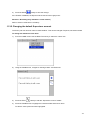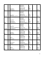
1
M PAT400 Series Portable Appliance Testers User Manual Thank you for purchasing the Megger PAT400 portable appliance tester. For your own safety and to get the maximum benefit from your instrument, please ensure that you read and understand the safety warnings and instructions before attempting to use the instrument. These instruments are designed and manufactured by: Megger Instruments Ltd Archcliffe Road Dover Kent CT17 9EN England Megger Instruments Limited reserves the right to change the specification of these instruments at any time without prior notice. 2 CONTENTS X.1 Unpacking the carton.............................................................................................................................. 5 X.2 Safety Warnings ...................................................................................................................................... 5 X.3 Symbols used on the instrument........................................................................................................... 6 1. Instrument Layout............................................................................................................................................ 7 1.1 Overview of the PAT400 ......................................................................................................................... 7 1.2 Instrument layout .................................................................................................................................... 8 1.3 Button functions...................................................................................................................................... 9 1.4 HOT KEY descriptions ............................................................................................................................ 9 1.5 Display information............................................................................................................................... 10 1.6 Screen navigation ................................................................................................................................. 10 1.7 Text fields (free form box) and Drop down boxes.............................................................................. 10 1.8 Battery and fuse location, fitting and replacement............................................................................ 11 2. Getting started ............................................................................................................................................... 14 2.1 Switching ON the PAT400 .................................................................................................................... 14 2.2 HOME screen explained ....................................................................................................................... 16 2.3 Switching off the PAT400 ..................................................................................................................... 16 3. Testing with a PAT400................................................................................................................................... 17 3.1 Connecting an asset to the PAT400 .................................................................................................... 17 3.2 Testing an asset .................................................................................................................................... 18 3.3 Test progress ........................................................................................................................................ 23 3.4 Remote probe and clip.......................................................................................................................... 24 3.5 Short circuit assets ............................................................................................................................... 27 3.6 Aborting a test ....................................................................................................................................... 28 3.7 Completion of testing ........................................................................................................................... 28 3.8 Test fail screen ...................................................................................................................................... 28 3.9 Visual failure .......................................................................................................................................... 29 3.10 Repair code............................................................................................................................................ 30 3.11 Cable compensation ............................................................................................................................. 31 3.12 WARNINGS ............................................................................................................................................ 32 4. Using the memory.......................................................................................................................................... 34 4.1 Important overview ............................................................................................................................... 34 4.2 Saving a test result ............................................................................................................................... 35 5. Adding assets to memory ............................................................................................................................. 37 5.1 Adding assets to memory before testing ........................................................................................... 37 5.2 Copying the previously added asset................................................................................................... 38 6. Editing and deleting assets and results ...................................................................................................... 40 6.1 Editing asset data.................................................................................................................................. 40 6.2 Deleting assets ...................................................................................................................................... 41 7. DATA – Test results and data transfer......................................................................................................... 42 7.1 Backup to USB memory stick .............................................................................................................. 42 7.2 Importing / restoring data from USB memory stick ........................................................................... 43 7.3 Export results to CSV ........................................................................................................................... 45 7.4 Accessing test results .......................................................................................................................... 46 8. Test groups .................................................................................................................................................... 49 8.1 Creating a test group ............................................................................................................................ 49 8.2 Allocating test groups to Hotkeys ....................................................................................................... 51 8.3 Editing a test group............................................................................................................................... 53 8.4 Deleting a test group............................................................................................................................. 54 8.5 Repeated Tests...................................................................................................................................... 55 9. Quick test - QT ............................................................................................................................................... 56 10. SETUP menu options ................................................................................................................................ 58 10.1 Clients .................................................................................................................................................... 58 10.2 Locations ............................................................................................................................................... 61 10.3 Company ................................................................................................................................................ 64 10.4 Quick test configuration ....................................................................................................................... 64 10.5 Date / Time settings .............................................................................................................................. 65 10.6 Changing Language.............................................................................................................................. 66 10.7 Restoring default settings .................................................................................................................... 67 10.8 ABOUT - PAT400 software version and Megger contact details ...................................................... 69 3 11. PAT400 enhancements: Firmware release V2.40 ................................................................................... 70 11.1 User names, account status and Login .............................................................................................. 70 11.2 Power Up and Log in/Log out options ................................................................................................ 71 11.3 Managing accounts............................................................................................................................... 73 11.4 Recovery Login ..................................................................................................................................... 82 12. Reverse L-N Polarity (not available on all instruments) ........................................................................ 84 12.1 To enable Reverse L-N Polarity testing: ............................................................................................. 84 13. Measure PE Option (not available on all instruments) .......................................................................... 87 14. PAT4 compatibility .................................................................................................................................... 89 15. Care and maintenance .............................................................................................................................. 91 16. Carry case .................................................................................................................................................. 92 Appendix A – Test types explained ...................................................................................................................... 93 A.1 Continuity & bond testing .................................................................................................................... 93 A.2 Insulation testing................................................................................................................................... 94 A.3 Leakage testing ..................................................................................................................................... 94 A.4 Load testing ........................................................................................................................................... 95 A.5 RCD testing............................................................................................................................................ 95 A.6 Power lead/extension lead testing ...................................................................................................... 96 A.7 Flash testing (PAT450 only) ................................................................................................................. 96 A.8 Parallel Earth Path WARNING:............................................................................................................. 96 A.9 PAT400 Factory Default Test Groups.................................................................................................. 98 Appendix B – Barcode sample table .................................................................................................................. 106 Appendix C - Specification .................................................................................................................................. 109 Appendix D - Ordering information .................................................................................................................... 111 Appendix E - Repair and Warranty ..................................................................................................................... 112 4 =================================================================== X.1 Unpacking the carton Unpack the carton contents carefully. There are important documents that you should read and keep for future reference. Please complete the pre-paid warranty card and return it to Megger Instruments Limited as soon as possible to help us reduce any delays in supporting you should the need assistance. UK carton contents PAT410, PAT420 and PAT450 1 PAT400 series appliance tester European carton contents PAT410, PAT420 and PAT450 1 PAT400 series appliance tester 1 Carry case + carry handle and strap 1 Carry case + carry handle and strap 1 Quick-start guide 1 Quick-start guide 1 Black test lead set with probe and clip 1 Black test lead set with probe and clip 1 IEC type power cord 30cm (Extension lead adaptor) 1 IEC type Power cord 30cm (Extension lead adaptor) 1 PC power supply test adaptor 1 Warranty card 1 Warranty card 1 Owners CD manual 1 Owners CD manual 1 Flash test lead (PAT450 ONLY) 1 Flash test lead (PAT450 ONLY) 1 Screen protector 1 Screen protector X.2 Safety Warnings The following safety warnings and precautions must be read and understood before the instrument is used. They must be observed during use. For safety, only connect the PAT to a supply that is properly earthed. If in doubt, the supply should be checked by a qualified electrician. Do not use the instrument if there are any signs of damage. All test leads, probes and clips must be in good order, clean and with no broken or cracked insulation. Probes and clips should be held behind the finger guard. Test leads not used during a measurement should be disconnected from the appliance tester. For dual voltage testers, both sockets can be live simultaneously. Only connect one asset to the PAT during testing. Tests should be carried out in the order recommended below. An appliance that fails a test should be repaired before further testing is carried out. Recommended sequence: 1. Earth bond/ continuity of the protective earth conductor (Class I devices) 2. Insulation test (or earth leakage) In addition further tests can be performed, but ONLY AFTER 1 & 2 above 3. Operation test 4. Leakage test Only perform an operational test after the earth bond and insulation tests have been completed, as this test operates at mains voltage. During testing, ensure no hazard will exist as a result of normal running or under fault conditions. During testing the unit under test (asset) should not be touched, other than using the appropriate accessories, as faulty appliances can present a shock hazard. Do not touch the exposed parts of test leads during tests as hazardous voltages may be present due to potentially faulty appliance. Do not touch the IEC extension lead socket pins especially during a test, as hazardous voltages may be 5 present due to a potentially faulty appliance Assets should not be routinely flash tested. Where flash testing is required, refer to further guidance on Flash testing, section A7 Replacement fuses must be of the correct rating and type. Refer to section 1.8 The USB connection marked thus should only be used by approved service personnel; nothing should be connected to the USB port during testing. Only use a NiMH rechargeable 8.4 V PP3 battery, do not use a non rechargeable type as this could become dangerous if charged by the instrument. Serviceable fuses should only be replaced with those that are suitably rated In case of an emergency use an easily accessible power point Only use Megger approved accessories with this product X.3 Symbols used on the instrument F G c Caution: risk of electric shock Caution: refer to accompanying notes. Equipment complies with relevant EU Directives Equipment complies with ‘C tick’ requirements Fuse This equipment should be recycled as electronic waste HV test lead in unlocked position HV test lead in locked position Battery type fitted Do NOT connect to mains supply 6 1. Instrument Layout 1.1 Overview of the PAT400 The PAT400 series of portable appliance testers are fully automated testers for the fast safety testing of portable electrical equipment. The PAT400s will operate from 230 Vac or, for UK variants 230Vac and 110 Vac supplies. The PAT400’s are ready to start testing, however the warnings must be read and understood before the testers are used. All operators should also be competent in the safety testing of electrical equipment and meet all the local legal requirements before testing. 7 1.2 Instrument layout 110 V test socket (UK Only) IEC/Extension lead return test socket Mains test socket Flash test socket Fuse checker Bond/continuity socket HOT KEYS Lead null post QVGA Colour display USB interfaces Up/Down/Left/Right navigation keys Power OFF OK button Home button TEST button Escape button Quick test access button Qwerty keypad 8 1.3 Button functions Button functions Power down – Prevents battery discharge Hot keys. Returns to HOME screen Function depends on adjacent display icon. Used for fast selection of options Escape – Exit screen without saving 1.4 HOT KEY descriptions Home screen SETUP screen Class 1 test groups Test group manager Class II test groups Change client Power/extension leads Change location Portable RCDs Bond lead null Add asset Edit asset Other Hotkeys Add Find asset View test result Edit Copy last asset List test groups Save Copy last asset (& increment asset ID) Delete Save/print label Re-run test Next page Previous page Login Print barcode Repair code pop-up box activation 9 1.5 Display information Menu bar – Provides navigation path and menu options. See NOTE below Main display area Display and test result information Hot keys Quick access to frequently used test groups, and other options. Additional menu options NOTE: Users tab is only available on Firmware version V2.4 and above. 1.6 Screen navigation Use the UP/DOWN and LEFT/RIGHT arrows to navigate around the menu and asset screens. Use the OK button or CR (enter key) on the keyboard to select or confirm an action. Use the HOME Use the ESC 1.7 button to return to the main menu button to exit or abort a function Text fields (free form box) and Drop down boxes When entering basic ASSET data, two types of text fields exist: 1) Free form boxes: 10 Free form box. Text or numbers can be entered as required. Text can be entered from a keyboard or barcode scanner. In some instances a “free form” box can become a “drop down” box, such as the asset ID field. In this case it will appear with the drop down icon as below: 2) Drop down boxes: Drop down boxes already contain a list of items. To access the list, navigate to the drop down box using the UP/DOWN arrows then press the OK button. Drop down box. Press OK to select from the available list. Alternatively, enter the first letter or number of the contents you require, and the search engine will jump to that entry. E.g. Enter “S” in the TEST GROUP box and the cursor will jump to SC1. If no contents start with that letter or number, nothing will happen. 1.8 Battery and fuse location, fitting and replacement Battery type: 1 x 8.4V NiMH rechargeable (PP3, IEC6F22, NEDA 1604,6HR61) Fuse type: PAT400 EU, DE, AU, US PAT400 UK 2 x 2A (F) HBC 50kA 600V (Part No. 90000-939) 1 x 250 Vac 100mA HBC 1.5KA (part No. 25413-295) An 8.4V IEC6F22 NiMH rechargeable battery is fitted to all PAT400s. The battery is continuously charged whilst the PAT400 is powered. The battery provides a fast re-boot function when the PAT400 is unplugged, moved between locations and 11 re-started within 5 minutes. The battery shall only be replaced by an equivalent rechargeable battery when the re-boot facility ceases to work. To replace the rechargeable battery: 1. Switch off the instrument. 2. Disconnect the instrument from any electrical circuits. 3. Remove the battery cover. 4. Remove the old battery and refit new battery following correct polarity (as marked on the battery compartment) 5. Replace the battery cover. Warning: Only use NiMH batteries! Do not attempt to recharge non-rechargeable (Primary) cells in the PAT400. Doing so may result in instrument damage and may cause personal injury. 12 For Fuse replacement Warning: 1. 2. 3. 4. 5. 6. 7. Fuses are at mains potential. The electrical supply MUST be disconnected prior to removing the fuse cover. Switch off the instrument. Disconnect the instrument from any electrical circuits. Remove the fuse cover on the underside of the PAT tester. Remove each fuse in turn and check for failure. Replace as necessary. If no fuses have failed, contact Megger Technical services group on 44 (0) 1304 502 102. Replace fuse cover when complete. Note: symbol on the batteries is a reminder not to dispose of them with general The waste at the end of their life. Spent NiMH batteries are classified as Portable Batteries and should be disposed of in the UK in accordance with Local Authority requirements. For disposal of batteries in other parts of the EU contact your local distributor. Megger is registered in the UK as a supplier of batteries. The Registration number is BPRN00142 13 2. Getting started 2.1 Switching ON the PAT400 1) Connect the instrument to a suitable electrical supply, either 230 Vac (or 110 Vac for UK instruments). For testing 230 V electrical equipment, connect the PAT tester to a 230 V electrical outlet. For testing 110 V electrical equipment, connect the PAT tester to a 110 V electrical outlet, using the optional 110 V to 230 V supply lead adaptor. Refer to section 3 for further details. The appliance tester will automatically start when connected to the mains supply. IMPORTANT: DO NOT connect any equipment to the PAT tester until it has been switched on and passed its self test. Connected equipment will create a relay error and necessitate restarting the PAT tester. Power should be disconnected and reconnected. 2.1.1 Start up- initialisation The first time the PAT tester is started the instrument will ask for the operating language, time and date to be set. 1) Use the UP/DOWN arrows to select the operating language from the options listed. 2) Press OK when complete 14 3) Using the RIGHT/LEFT and OK keys to enter the date and time Date format is DD / MM / YYYY Time format is 24 Hr Hr / Min / Sec 4) Press the SAVE HOTKEY to accept changes. Further changes can be made in the menu SETUP options section 10.5 On completion of the initialisation the following warning screen is displayed when the PAT tester is switched on. UK configured PAT400 instruments NOTE: 5) Non- UK configured PAT400 instruments This screen is not displayed if the PAT tester is re-started within five minutes of being un-plugged, or when the PAT tester restarts from the same screen as before. Press OK to confirm you have read and understood these warnings. The instrument will display the following HOME screen when all initial tests pass. 15 2.2 HOME screen explained The HOME screen is the start point of all testing. Menu functions: Home Setup DATA Users 2.3 Class I test groups Test launch screen HOT KEY access Instrument status Client Location Company Quick tests Date/Time Language Default settings About Class II test groups Class IEC (Power) and extension lead test groups Plug-In RCD test groups Add asset - fast access Backup to USB Restore from USB Export to USB (CSV) View results Login / Logout Expert Options Manage Users Switching off the PAT400 2.3.1 Normal Power-Off To switch off the tester, press the RED off button . The display will show the message “It is now safe to remove power” Now the mains plug can be removed from the supply. Switching off using this button prevents the “FAST Re-start” battery from discharging unnecessarily. 2.3.2 FAST Re-start If the tester is to be moved to a new location and testing continued, simply unplug the unit from the mains supply and reconnect it in the new location. The appliance tester will enter a hibernation mode during the move and restart instantly from the point power was disconnected, without any delay. Any test results are retained. On reconnection the previous test result can still be saved. The rechargeable 8.4 V NIMH battery is used to maintain hibernation status whilst unplugged. This battery is continuously charged whilst the appliance tester is connected to the mains supply. Continuous use of the hibernation mode will discharge the battery. Should the move take longer than 5 minutes, the appliance tester will leave hibernation mode and complete a full power down. 16 3. Testing with a PAT400 3.1 Connecting an asset to the PAT400 Assets are tested through the test connectors on the top of the instrument. An asset is simply plugged into the appropriate socket. A power cord (IEC lead), or an extension lead needs to be “wrapped back” to the small IEC socket on the top of the instrument. This allows automatic testing of continuity and polarity without connecting the remote probe. Standard Class I and Class II assets will also use the additional remote probe for BOND, INSULATION or LEAKAGE testing. The instruction to connect it is displayed on the screen at the appropriate time. The following drawings show how the asset under test should be connected at the start of testing. NOTE: The dotted line indicates where a 110 V asset would be connected (UK PAT testers only). Other test leads may need to be connected during the test sequence. Follow onscreen instructions. NEVER CONNECT MORE THAN ONE ASSET AT A TIME. 3.1.1 Connecting a Class I or Class II asset. To connect standard Class I or Class II equipment to the PAT400: 1) Plug the asset into the 230 V test socket on the PAT400. To connect 110 V equipment to the PAT400: 1) Plug the asset into the 110 V test socket on the PAT400. 3.1.2 Connecting an IEC type power cord or 110 V (Power) lead To connect a standard IEC type power cord (computer type power lead) to the PAT400: 1) Connect the mains plug to the mains test socket on the PAT400. 2) Connect the IEC plug to the IEC socket. To connect a 110 V power lead, use the 110 V to IEC plug adaptor (see optional accessories). 1) Connect the 110 V mains plug to the 110 V test socket 2) Connect the free end of the 110 V power lead to the 110V adaptor plug. 3) Connect the 110 V adaptor IEC connector to the IEC socket 17 on the PAT400. 3.1.3 Connecting an extension lead To connect an extension lead to the PAT400: 1) Connect the mains plug to the mains test socket on the PAT400 2) Using the extension lead adaptor, connect the furthest socket on the extension lead to the IEC socket on the PAT400. To connect a 110 V power lead, use the 110 V to IEC plug adaptor (optional accessory). 1) Connect the 110 V mains plug to the 110 V test socket 2) Connect the free end of the 110 V power lead to the 110V adaptor plug. Connect the 110 V adaptor IEC connector to the IEC socket on the PAT400. 3.1.4 Connecting a portable RCD To connect a portable RCD to the PAT400: 1) Connect the RCD to the 230 V test socket on the PAT400. 2) Using the IEC test lead adaptor, connect the IEC plug of the adaptor lead into the IEC socket on the PAT400. 3) Connect the MAINS plug of the IEC test lead adaptor into the RCD. 3.2 Testing an asset The PAT400’s are designed to automatically test electrical equipment, using TEST GROUPS. A “TEST GROUP” is a specific group of tests suitable for the type of asset being tested. The PAT tester is shipped with a pre-defined set of test groups. However others can be added as required, up to a maximum of 100, see section 8. Before a test will run, a TEST GROUP must be selected. There are three options to start the test sequence: OPTION 1 OPTION 2 OPTION 3 Select a test group from the HOTKEY options Press the TEST button – This takes you to the TEST ASSET screen. Scan the asset ID with a bar-code scanner, then press TEST (asset details must already be stored in the PAT400), otherwise PAT400 defaults to ADD ASSET screen. 18 Option 1: Starting a TEST – USING HOT KEYS .1 Select a Class I, Class II, IEC/extension lead or RCD test group by pressing one of the HOT KEY options: A list of TEST GROUPS are displayed that are relevant to that type of equipment Example: Class I test groups Class I test groups Class II test groups Class IEC (Power) and extension lead test groups Plug-In RCD test groups Add Asset - fast access .2 Select one of the test groups by pressing the relevant number, then the TEST button. or Press the number twice to start the test sequence. or Scroll down to the required test group and press TEST. For more Information on test groups, adding, editing, configuration or deletion, go to section 8. Option 2: Starting a TEST – PRESSING THE TEST BUTTON .1 From the HOME screen, press the TEST button. The display will show the TEST ASSET page, as below: Find asset Search for TEST GROUPS Press once for direct entry Press twice for drop down box. Add ASSET Edit ASSET .2 Type in the “Asset ID” if available and press OK. 19 If the asset is already in the database the details of the asset will be displayed as below: Press the TEST button and the test sequence will commence. Go to 3.3 TESTING PROGRESS. Alternatively to search through the asset database, press the FIND ASSET down box of Asset IDs will appear. Hotkey. A drop If you know the Asset ID you wish to find, start typing in the Asset ID. The search engine will jump to the Asset IDs that start with those characters. To ADD an asset, simply press the ADD ASSET .3 Hotkey. If the entered asset is not in the database, the following information box will appear: Press OK to add a new asset. A blank Add Asset screen will appear as below. This only contains the Asset ID entered in the previous screen, plus current client and location. If no client and location have been added, these will say “default”. 20 Copy last asset added from list Copy last asset added and increments Asset ID to next available number. * Indicates mandatory fields that are required to save the asset data. Further information on the COPY LAST ASSET ID Hotkey and COPY & INCREMENT ASSET Hotkeys can be found in section 5. (A new asset ID can be added and saved at this stage, but it is recommended that this is added after testing is completed). .4 Press the DOWN arrow to access TEST GROUPS. .5 Press OK to access the drop down list of test groups. Use the UP/DOWN arrows to scroll through the list of test groups and then press OK OR Start typing the name of the test group. The cursor will jump to the relevant test groups with that letter or number. Entering more than one letter will refine the search further. Then press OK. Add any additional data in the available fields as required. .6 Press TEST to commence testing. .7 Go to section 3.3 Test Progress Note: Only a TEST GROUP is required to start testing. 21 On completion of a test, only Asset IDs and Test groups have to be added before the test is completed. All other data is optional. NOTE: and type in the test If NO Asset ID is entered, press the Test Group Hotkey group. Alternatively press the hotkey twice to select the test group drop down box. Press OK to list all test group options, scroll down the list to select desired test group and press OK to accept. NOTE: Pressing the Right arrow key will “Page Down” the list. FURTHER DETAILS ON ADDING ASSETS CAN BE FOUND IN SECTION 5. Option 3: Starting a TEST – USING A BARCODE SCANNER .1 From the home page, scan the Asset barcode with the optional barcode scanner. If the ASSET ID does NOT exist in the PAT database, the PAT will jump to the ADD ASSET screen and the ASSET ID will appear. .2 If the asset information matches the asset to be tested the completed TEST ASSET screen will appear as below: Find Asset Search for TEST GROUPS Press once for direct entry Press twice for drop down box. Add ASSET Edit ASSET Check the asset information matches the ASSET to be tested. If so, Press TEST and go to section 3.3 TEST PROGRESS. If the asset information does not match the asset to be tested, check the CLIENT is correct. The same ASSET ID can be used for different clients, but one client cannot have duplicate asset IDs. If the asset ID does not exist the screen will jump to Add Asset screen and automatically fill the ASSET ID field with the scanned barcode data. .3 Press the DOWN arrow to move to Test Groups. The TEST GROUP is selected by pressing OK and selecting from a drop down list. Typing the first letters or numbers of the test group will allow the search engine to jump to those test groups without having to scroll down the list. 22 Additional information can also be added, but this is not essential. NOTE: .4 3.3 When scanning an Asset ID that exists in the database under a location that is different to that set in the PATs current status, a yellow warning indicator will show on the Location field as below. Go to section 10 for additional information on Clients and locations. Press the TEST button. Go to section 3.3 TESTING PROGRESS for further information on the test sequence. Test progress The PAT400 displays all tests to be performed within the selected test group. Each test is run sequentially and the results displayed for each test before proceeding to the next test. A “FAIL” on any test will prevent further testing for safety purposes. Test screen example: Class I asset 23 Test results screen List of tests in test group Green – Test passed Amber – Test in progress Grey – Test pending Test results column Test limits column Pass limit set for this test Actual measurement result Current test values or Instructions during the test sequence Interruption to automatic testing Testing proceeds automatically unless an action is required from the operator. Follow “on-screen” instructions as they appear. 3.4 Remote probe and clip Some tests will require the use of the remote probe and clip. These are used where the asset under test has no earth return (Class II assets). Test using the remote probe include: Insulation testing on Class II equipment Continuity/bond testing on Class I equipment Touch leakage testing Differential leakage test on Class II Substitute leakage on Class II The PAT400 will instruct the operator when the remote probe needs to be connected. Example of remote probe application Class II insulation test (Riso) Live and neutral are shorted together automatically in the PAT (RED LINK) and a voltage (250 V or 500 V) is applied between the shorted L/N and the remote probe. The probe is connected to any metallic locations on the “appliance under test” to ensure there is no breakdown of the insulation. 24 The insulation test probe is connected to all exposed metal parts to ensure electrical separation from earth. 3.4.1 Test lead resistance null The resistance of the Bond lead can be “nulled” to remove the lead resistance from the measured resistance. This is important when testing very low resistances where the test limit is set to 0.1ohms. Also, the resistance of an extension lead (IEC or Power cord) can be nulled, if the lead is longer than the Red test lead supplied with the PAT. Symbols used: Test lead null is set Extension lead adaptor null is set, see section 3.4.2 Both Test lead and extension lead adaptor null are set To null the test lead resistance of a bond lead: 1) From the HOME screen, use the RIGHT arrow key to select the SETUP tab. 2) Press the NULL Hotkey. The Lead Null screen will appear as below: (If a lead null value is already set the lead null symbol 3) will be displayed) Connect the Black bond lead between the Bond socket and the Zero post on the front panel as below: 25 4) Press the TEST button. The PAT400 will display the value of the test lead as a Null SET value, and display the The 5) symbol in the top of the screen as below: displayed inside means an extension lead null is also set. To remove the Bond Lead Null select the “Remove Lead Null” and press the TEST or OK button. The symbol will disappear. 3.4.2 Extension Lead Adaptor Resistance Null Some tests require using an IEC lead or the short extension lead adaptor supplied with every PAT tester. An example of this is testing a multiple sockets extension lead: Extension lead adaptor The resistance of the extension lead adaptor may be removed by performing an extension lead null. 1) From the HOME screen, use the RIGHT arrow key to select the SETUP tab. 26 2) Press the NULL highlighted: Hotkey. The Lead Null screen will appear with the Set Lead Null option (If an extension lead null value is already set the lead null symbol will be displayed) 3) Connect the extension lead adaptor between the Mains test socket and the IEC socket on the front panel as below: 4) Scroll down to select “Set Extension Lead Null” on the menu 5) Press the TEST button. The PAT400 will display the value of the test lead as a Null SET value, and display the symbol in the top of the screen as below: To remove the extension lead null select the “Remove Extension Lead Null” and press the TEST or OK button. The 3.5 symbol will disappear. Short circuit assets Some assets may appear to the PAT400 to be short circuit. This can be caused by large inductive loads. In such cases, the following warning message will be displayed: Warning: Asset may be short circuit. Press TEST to continue, ESC to abort 27 Only if the operator is certain the equipment is not a short circuit, press TEST, otherwise press Esc to abort the test 3.6 Aborting a test All tests can be aborted at any time by pressing the TEST button or Esc (escape) button. 3.7 Completion of testing On completion of testing all test fields should turn green as below. The test results are displayed in the centre column with the pass limits for that test group on the right. Repeat test sequence Repair codes Print bar code label & SAVE results to memory SAVE results to memory On completion of testing, the following options are available: Re-test asset using current test group. Warning: test data will not be saved for the previous test. Repair codes – Allows repair details to be added to asset test results – See section 3.10 below. Save the test results to memory and print a barcode label (a Megger USB barcode printer must be connected prior to requesting this function). Save test results to memory and return to the initial screen. Go to Section 4 to learn about using the memory, or Section 4.2 Saving a test result to memory. To return to the HOME screen without saving the results press HOME button 3.8 Test fail screen Should an asset fail a test at any stage, the test sequence is stopped and the screen message ASSET FAILED is displayed: 28 Repeat test sequence Repair code Print bar code label & SAVE results to memory SAVE results to memory Example: Asset has failed the insulation test. Pass limit set to 1.0 MΩ, Measurement recorded at < 0.1 MΩ. The same options are available as an asset that has passed. See Section 3.7 for completion of testing. 3.9 Visual failure If the current test group contains a visual test sequence then the visual test popup will appear. This allows the user to log mechanical faults on the asset under test, such as a broken plug or damaged appliance cord, the Esc key should be used to exit the test sequence during the Visual Inspection and initiate a Visual Failure, as below: 1) During the Visual inspection option the “Visual Test” will be highlighted in yellow, as below: 2) Press the Esc key to initiate a Visual Failure. The display will show a Visual Test Failure screen as below: 29 3) Three types of information can be entered: a) Notes - To describe the type of failure. b) Check boxes - Quick entry for standard failure types. c) Repair code - See Section 3.10 below 4) Press the TEST key to complete the test process. The display will now show the TEST FAILED screen. 5) Press the SAVE Hotkey to save the results or the SAVE and PRINT Hotkey to save the results and print a barcode label. 3.10 Repair code A repair code can be entered at the completion of testing. To enter a repair code: .1 Press the .2 Enter any notes as appropriate then press OK, followed by the DOWN arrow. .3 Enter an appropriate repair code. Examples of the repair codes used in PowerSuite are given below: Hotkey and the following popup appears: 30 On completion of the repair code screen press the TEST key to log the changes, then press the SAVE or SAVE and PRINT Hotkeys to store the results. 3.11 Cable compensation A power cord, appliance lead or extension lead will frequently exceed the nominal length and consequently the resistance limit set in the standard test groups. Rather than having many test groups with different lead lengths, the “Cable Resistance Calculator” screen allows the limit of a Bond or Continuity test to be modified after the measurement. On a failed test, entering the length of the lead and the conductor cross section, the pass limit is adjusted to the correct resistance. The result is then passed or failed, as necessary. To apply cable resistance calculation: 1) When a continuity or Bond test fails, the screen message alert will be displayed: 2) Press OK to access the Cable Resistance Calculator as below; 31 OR Press Esc to fail the Asset and save or abort the results, OR Press “R” to re-run the continuity test. 2 3) Enter the cable Length in metres and the conductor Cross-Section (mm ) OR a Resistance can be entered if this is known. 4) Press TEST to complete the test. The PAT400 will now proceed to the next test if the resistance was a PASS or to a fail screen if the resistance was still outside the modified limit. See also Section A.6 for cable length limitations and RCD protection on long leads. 3.12 WARNINGS 3.12.1 Power-On tests Running a leakage or load test will operate the asset under test. Some assets, such as vacuum cleaners, disc cutters etc can draw high initial load currents (Inrush current). The PAT400 will under these circumstances report the asset has a short circuit. If this warning is displayed, it is recommended the following actions are taken: 1) Where possible check the asset does not have a short circuit (the fuse would normally be blown in such circumstances, prior to it being replaced). 2) Proceed ONLY if you believe the asset is not a true short circuit, but has a high inrush current. 3.12.2 Reversed supply UK instruments: The PAT400 will detect a reversed polarity (Phase – Neutral) supply and abort the initialisation. The display will show the warning: ERROR 82: Mains polarity reversed European instruments: The instrument will pass initialisation and display the Home screen. The supply polarity will be shown as “Reversed”. 3.12.3 Supply earth fault 32 The PAT400 will test for a good supply earth during initialisation. A faulty or missing earth will return the error: Error 73 – Mains supply Earth Fault 3.12.4 Parallel earth paths If the PAT400 detects more than one earth path, the warning: Unable to verify earth connection, Parallel paths may exist. Refer to user guide. The PAT400 has detected more than one earth path during the Earth continuity, Earth bond, Insulation or Earth leakage tests. Refer to Appendix A.8 for further details. 3.12.5 Database full Exceeding the storage capacity of the database will create the following warning: Error - Database Full. Unable to save data! Press OK to continue The test result will NOT be saved. To free up memory for further test results: 1. Backup the existing database to a USB storage device. 2. Delete records from the PAT400. See Section 4 for further information on PAT400 memory. 33 4. Using the memory 4.1 Important overview All records are stored under a “client”. The PAT400 can store up to 100 (50 on firmware releases prior to 2.20) clients. Each client can have up to 2 000 (50 on firmware releases prior to 2.20) Locations. There is a maximum of 25 000 total locations per database. The client and locations are configured in SETUP, refer to Section 10. The PAT400s are shipped with the client and first location set to “default”. All results will be stored under this “default” client and location unless changed in SETUP. These can be left as default, but it is recommended these are changed to the name of the client and location of the test site. See Section 10. Assets are stored with a minimum of an “Asset ID”, and a “Test Group”. A client CANNOT have duplicate Asset IDs, even if they are in several locations. However the same Asset ID can be used for different clients. Test results are stored and referenced to an Asset ID. The internal memory will store up to 10 000 test results. Entering an asset ID that already exists in the current client will generate a “duplicate asset ID” warning. Change the asset ID then press save. Assets can be saved to memory before or after testing. The add asset screen is shown below: Default Add Asset screen Add Asset screen with asset data to be saved COPY last ASSET COPY last ASSET and Increment Asset ID SAVE results to memory 34 Definitions of fields Field Limit Description Asset ID:* 10 000 Unique number or combined letters and numbers. Enter by typing from the keyboard or scanning a barcode. Separate clients can use the same ID. But one Client cannot have two identical Asset IDs. Test Group:* 100 Drop down box of available test groups. Press OK to access list, DOWN/UP arrow to select and OK to enter. Description: --- General description of asset (Cooling fan, hand drill etc). Serial Number: --- The manufacturer’s serial number. Fuse Rating (A): --- Fuse fitted to the mains plug (or internal fuse if using continental plugs). Room ID: --- Location of asset to room level. Retest Frequency (M): --- Repeat test frequency in months. The default is set to 12 months 1 Client: 100 Location: 2 000 Customers name – This is created in SETUP. 1 Site details. Each client can have multiple locations – This is created in SETUP. *Fields marked (*) are mandatory fields. Data cannot be saved unless these are completed. 1 Either DEFAULT or Client name and Location, required before data can be saved. Note: 4.2 Spaces can be saved as a Client or Location, but appear as blank fields when reviewed in Asset data. Saving a test result On completion of a test sequence, the message “asset PASSED” and the SAVE key will appear. 1) Press the SAVE Hotkey or press the SAVE and PRINT (a barcode label) barcode label and save. Hotkey to print a Note: A Brother P-Touch 2430PC must be connected to print a barcode label. 2) If no Asset ID was entered before testing started, the asset screen will be displayed as below. The test group will already be set, as this was selected when the test was run. 35 3) Enter the Asset ID. This can be via the keyboard or scanned in by barcode scanner. If an Asset ID already exists in memory, a “duplicate Asset ID” warning will be displayed. In this case, enter a different Asset ID number. Examples of Asset ID formats: (Asset IDs are limited to 20 characters) 0001, 0002, 0179, 7082 MEGGER0001, MEGGER0002 AA0001,AA0002, BF0001, BF0002 4) Press OK 5) Press the DOWN arrow and complete the additional asset data as required. Test Group, Client and Location cannot be changed in this screen. 6) When completed, Press the SAVE current client and location. Hotkey. The asset will be added to the memory under the SAVE results to memory To abort an “Add Asset” page, press Esc or HOME key. A warning will appear asking to confirm you wish to exit without saving data. To edit asset information go to section 6. 36 5. Adding assets to memory Assets can be saved to memory after they are tested, as above, or before any testing starts. Copying a previously added asset using the COPY ASSET INCREMENT ASSET ID Alternatively: 5.1 Hotkey or COPY ASSET AND Hotkey in Section 5.2. Asset data can be loaded from PowerSuite via a USB stick, Section 7.2. Adding assets to memory before testing 1) From the HOME screen, press the ADD ASSET appear: Hotkey. The following empty asset screen will COPY last ASSET COPY last ASSET and Increment Asset ID 2) Enter an ASSET ID, using the keyboard, or barcode scanner. 3) Select a TEST GROUP from the drop down list. 4) Completion of the remaining asset fields is optional. SAVE results to memory 5) Hotkey. The asset data will be saved to memory. The screen should display Press the SAVE the SAVED message and return to the HOME screen. 37 5.2 Copying the previously added asset 1) From the HOME screen, press the ADD ASSET appear: 2) To recall the last asset to the screen press the COPY ASSET Hotkey. This will recall the last asset added to the database of the current Client. The Asset ID can then be edited as required. 3) Change the Asset ID. The SAVE changed. Hotkey. The following empty asset screen will Hotkey becomes available after the ASSET ID has been OR To recall the last asset to the screen and INCREASE the Asset ID by one, press the COPY ASSET AND INCREMENT ASSET ID Hotkey. 38 4) Change any other asset information as necessary. 5) Press the SAVE Hotkey to save the ASSET to memory. 39 6. Editing and deleting assets and results All asset data can be edited or deleted as required. For deletion of Test Groups see section 8. For deletion of Client and Locations see section 10. 6.1 Editing asset data 1) From the HOME screen, enter the SETUP menu option by pressing the RIGHT arrow key. EDIT asset 2) Press the EDIT ASSET Hotkey. The EDIT ASSET screen should be displayed. Enter an Asset ID to be edited. Alternatively, to list the assets in the database, press the FIND ASSET Hotkey. This will produce a drop down box, FIND ASSET DELETE asset ADD asset Assets are sorted alphanumerically in ascending order. Press the OK key and then the DOWN arrow to scroll through the list, or use the RIGHT arrow key to page through the list. OR Type the desired Asset ID to jump to the matching item in the list. The search engine will find the 40 closest match as you type. Note: The first 2 000 Asset IDs are loaded into the drop down list. To access the next 2 000 assets, press and hold the RIGHT ARROW to scroll down to the bottom of the first 2 000 assets. Select ‘Next…’ from the bottom of the list. The Asset ID list will now load the next 2 000 assets. OR Where available type ‘next…’ to jump to the end of the list or ‘previous…’ to jump to the start of the list. 3) Edit the asset details as required and press the SAVE key to store changes. NOTES: To move the location of an asset, simply change the location in the Location list. It is not recommended to change the Client. Changing the Client will also change the appropriate asset list. However on exiting this screen the Client will revert to the original Client prior to any changes made here. 6.2 Deleting assets 1) From the HOME screen, use the RIGHT ARROW key to select the SETUP tab. 2) Press the EDIT ASSET 3) Scroll down the Asset ID field as in 6.1 above. When the required asset is displayed, press the DELETE Hotkey. The EDIT ASSET screen should be displayed Hotkey. 4) A screen message to confirm the deletion is displayed. 5) Press OK to confirm or Esc to abort. WARNING: The asset and its associated test records will be deleted. This deletion is not reversible. For Deletion of Clients and Locations see Section 10. 41 7. DATA – Test results and data transfer Data storage – backup and restore The PAT400 can store up to 10 000 electrical assets with associated test records. Megger STRONGLY RECOMMEND this data is backed up frequently. MEGGER CANNOT ACCEPT RESPONSIBILITY OR ANY LOST DATA HOWEVER CAUSED. The backup and recall operations are extremely fast. 10 000 records can be backed up to a USB stick in <20 seconds. Smaller databases are significantly faster. The file format for data backup is a db file. DO NOT ATTEMPT TO EDIT THIS FILE. Corruption of this file shall prevent further transfer back to the PAT400 or to PowerSuite. Export to CSV file Test results can also be exported to a CSV (comma separated value) file. This can be viewed with Microsoft Excel. See Section 7.1, 7.2 or 7.3 for full details of Backup, Restore and Export options. 7.1 Backup to USB memory stick 1) Connect a USB stick to either of the type A USB sockets on the front of the PAT400. ‘Type A’ USB socket. 2) Use the RIGHT ARROW to select DATA in the main menu options. 3) Use the DOWN arrow to select “backup to USB” and press OK. 4) Enter the name of the file you wish to create. The file name can be up to eight characters, A to Z and 0 to 9. Do not use any other characters. 42 5) Press OK to initiate backup. If the file name clears without backup starting, the file name contains excluded characters. Only 0 to 9 and A to Z should be used. 6) On completion the display will show the message “Backup complete”. There are no limits to the number of times you can backup a database. The stored file is a “.db” file. Do not attempt to edit this file as this can corrupt the data and prevent further use of that file. If the USB device is not recognised the following message will be displayed. This error can be caused by a faulty USB stick. Replace the USB stick with another type and try again. Note: A USB stick may take a few seconds to be recognised by the PAT400. 7.2 Importing / restoring data from USB memory stick Importing data from PowerSuite to the PAT400 or restoring data from a saved file are the same. The file must be in a .db format and located in the root directory of the memory stick. This would either have been created by the PAT400 as a backup file or created from PowerSuite for import into the PAT400. 1) Connect a USB stick (containing the .db file) to either of the Type A USB sockets on the front of the PAT400 ( 2) Type A’ USB socket). Select the “Restore From USB” option in the DATA menu, as below: 43 WARNING: Importing or restoring a file will overwrite the existing assets, results, test groups, clients and locations in the database. 3) Press OK to continue. 4) The PAT400 will search for any database files in the root directory. A drop down box appears. Press the OK key and then the DOWN arrow to scroll through the list, or use the RIGHT arrow key to page through the list. OR Type the desired file name to jump to the matching item in the list. The search engine will find the closest match as you type. 5) Press OK to accept the file for import or restore. The PAT400 will display a message: 44 6) Press OK to accept the file for import/restore. 7) The file will be imported. On completion a message will be displayed and the buzzer will sound. DO NOT SWITCH OFF THE PAT400 DURING THE USB OPERATION! 7.3 WARNING: Importing or restoring a file will overwrite the existing assets, results, test groups, clients and locations in the database. Always ensure existing data has been backed up prior to importing new data. Note: Databases restored from previous firmware versions will be automatically upgraded. Once upgraded, the database will no longer be compatible with older firmware versions. To maintain compatibility between multiple PAT400s upgrade all PATs to the same firmware version. Databases restored from different PAT models may have tests that are incompatible with the model being imported into. For example a PAT450 can have Bond testing setup, where PAT410 models do not have this test. In this case the test will be skipped during testing. Export results to CSV Assets and test results can be exported to a CSV file format. This file can be opened with a CSV viewer. To export data and test results to CSV: 1) Connect a USB stick to either of the type A USB sockets on the front of the PAT400. 45 2) Select Export Results to USB and press OK. The following screen will appear. 3) Enter a name for the CSV file. Up to 8 characters can be used. Use letters and/or numbers. Press OK when ready. 4) The CSV file will be saved to the USB memory stick. On completion the following message will be displayed and the buzzer will sound. Note: Exporting large amounts of data to CSV can take a significant time to complete. Once started a CSV export cannot be aborted. 7.4 Accessing test results Test results for each asset can be viewed through the View Results menu option of the DATA tab as below. Only test results belonging to the current Client and Location can be viewed. 7.4.1 To view a test result: 1) From the HOME screen, use the RIGHT ARROW key to select the DATA tab. 2) Use the DOWN arrow to select VIEW RESULTS and press OK 46 The ‘View Test Results’ screen will be displayed as below: FIND asset ADD asset EDIT 3) Enter the Asset ID or press the FIND ASSET this may take a few seconds. Hotkey. If there are a large number of Assets IDs, 4) When the desired Asset ID has been found, Press OK to accept. The VIEW TEST RESULTS Hotkey will appear as below. VIEW TEST RESULTS 47 5) Press the VIEW TEST RESULTS asset as below. 6) To exit this screen press HOME or Esc. Note: 7.4.2 Hotkey. The Test Results screen will be displayed for that Barcodes can be printed by using the PRINT BARCODE Hotkey Printing barcode labels Duplicate barcode labels can be printed from the VIEW TEST RESULTS page. This allows replacement of labels if they are damaged or multiple labels are required for an asset. To print a barcode label: 1) Enter the Test Result screen as above. 2) Ensure the Brother 2430PC barcode label printer is switched on and connected to the USB port of the PAT400. 3) Press the PRINT BARCODE Hotkey. 48 8. Test groups Overview of test groups Test groups are used to simplify the testing of an asset. A test group is a collection of tests that when run, perform all the tests allocated to that test group. The PAT400’s are shipped with a range of test groups for the majority of electrical equipment that will require testing, as detailed below. Additional test groups can be added up to a limit of 100. Existing test groups can be edited or deleted as required. 8.1 Creating a test group 1) From the HOME screen, use the RIGHT ARROW key to select the SETUP tab. TEST GROUP MANAGER 2) Press the TEST GROUP MANAGER Hotkey Add a TEST GROUP Edit a TEST GROUP Delete a TEST GROUP 3) Press the ADD Hotkey to add a new test group. The Add Test Group screen will appear. 49 Note: If the number of test groups reaches 100, the ADD 4) Hotkey will change to a Icon. Complete the fields as required. An example of a typical standard Class I test may look like: Next page Definitions to fields: 1 NAME : 1 DESCRIPTION : Test group name - This can be up to 10 characters - For compatibility with PAT4 see section 11 Text string - Keyboard or Barcode entry SUPPLY: Asset operating voltage. VISUAL: Check box EARTH BOND Check box – configuration options available on second page CONTINUITY Check box – configuration options available on second page INSULATION Check box – configuration options available on second page POLARITY Check box – configuration options available on second page CLASS Drop down box. This is required so the instrument knows which test connectors are to be used. 50 Options FLASH - Class 1 - Class 2 - EXT Check box – configuration options available on second page LEAKAGE Check box – configuration options available on second page LOAD Check box – configuration options available on second page RCD Check box – configuration options available on second page 1 5) These fields require mandatory data. They cannot be left blank. When complete, press the NEXT PAGE will appear as below: Hotkey. The test options for each of the selected tests Previous page Save test group 8.2 6) Now the test limits, test times and repetition settings can de adjusted for each test if required. Use the UP/DOWN arrow keys to navigate the screen. All options are drop down boxes. Press OK to access each drop down list. 7) On completion press the SAVE 8) The test group can now be allocated to one of the test group HOT KEYS. Hotkey. Allocating test groups to Hotkeys Test groups can be allocated to one of four TEST GROUP Hotkeys on the HOME screen. To allocate a test group: . 1) Press one of the four TEST GROUP Hotkeys 2) A list of test groups numbered 1 to 9 will appear. Blank fields indicate a number that has not yet been allocated a test group. 51 Class I Class II Power cord / Extension lead RCD Add Asset Using the DOWN ARROW, navigate to the desired row (1 – 9) as below: Press OK to access the drop down list of available test groups. 3) Select the required TEST GROUP and press OK. The TEST GROUP will be allocated to the selected field. 52 NOTE: 8.3 The TEST GROUPS can be freely allocated to any of the nine fields and in any of the four Hotkeys. If desired a CLASS I TEST GROUP can be allocated to the RCD Hotkey for example. Editing a test group Each test group can be edited or deleted NOTE: When restoring a database the test groups will also be overwritten. Always backup your test records before restoring a database. To edit a test group: 1) From the HOME screen use the RIGHT ARROW key to select the SETUP tab. 2) Press the TEST GROUP 3) Press the EDIT TEST GROUP 4) Press the OK button to access the drop down list. Hotkey. Hotkey. 53 Select the test group to be edited and press OK to accept. The test group settings can be adjusted and saved as per the test group ADD function above. WARNING: 8.4 Changing a Test Group will affect all assets that use that test group. Deleting a test group To delete a test group: 1) From the HOME screen use the RIGHT ARROW key to select the SETUP tab. 2) Press the TEST GROUP MANAGER 3) Press the DELETE Hotkey. Hotkey. Delete 4) Press OK to activate the drop down list. Select the required test group then press OK. 5) Press the DELETE 6) The display will ask for confirmation that the test group is to be deleted. 7) Press OK to accept, Esc to exit. Hotkey. 54 Note: 8.5 A test group cannot be deleted whilst there are assets in the database that are using that test group. Repeated Tests It is possible to create test groups with repeated Bond, Continuity, Insulation and Flash tests. An example screen is shown below. Repeated tests are setup by choosing an option in the Cycles column. Bond and Continuity test have the ability to be repeated a set number of times (1 to 10) or repeated indefinably by choosing the ∞ symbol. For example you may wish to test a multi way extension lead which has 4 sockets. In this case you would set the Bond Cycles option to 4, this will automatically perform 4 Bond test and record the worst Bond resistance. An example screen is shown below: If a Bond or Continuity test fails then the user is always allowed to repeat the test. If the test is repeated then the failed results is disregarded. You may wish to repeat a test in this way if the test probe did not make proper contact with the appliance. Insulation and Flash test can also be repeated by selecting the ∞ symbol in the Cycles column. This feature is convenient for testing appliances that have multiple exposed conductive areas. 55 9. Quick test - QT The Quick Test (QT) key provides instant access to continuity, bond, insulation, leakage, RCD, load (Operational) and flash testing, without having to create a test group. NOTE: Some tests shown below may not be available, depending on the instrument being used. Running a quick test 1) Press the QT key on the keyboard. The display will show a numerical list of options. Example of QT screen options for a PAT450 2) Press the number key associated with the test you wish to run. Example - Earth Leakage Note: Where a test has several options, such as Earth Leakage, a sub menu of options will appear. 3) Navigate through the sub-menu options if available. 4) Press OK or TEST key to start testing. 56 5) Follow on-screen instruction as necessary. On completion of the test the final measurement will be displayed. Quick test times can be changed in SETUP. Refer to section 10.4 57 10. SETUP menu options The SETUP menu options allow changes to the instrument configuration that cannot be accessed by Hotkeys. 10.1 Clients The PAT400s are shipped with the CLIENT and LOCATION set to DEFAULT. This can be changed, or additional Clients and locations can be added, edited or deleted. The DEFAULT CLIENT and LOCATION can only be deleted after other additional CLIENTS AND LOCATIONS are added. 10.1.1 Adding Clients 1) Select CLIENT from the SETUP menu and press OK. 2) The Client screen will be displayed with the ADD, EDIT and DELETE Client Hotkeys as below: 3) Select the ADD 4) Complete the text fields with the necessary Client information. Client Name is mandatory; once it has been saved the name can not be changed. Additional data is optional. Hotkey to add a new Client to the database. 58 5) On completion, press the SAVE Hotkey. 6) The display automatically jumps to the ADD LOCATION screen. 7) Add the location details. Only Location name is mandatory. 8) On completion, press the SAVE Hotkey. A new CLIENT and LOCATION has been added to the database. The current CLIENT and LOCATION has been updated to the new CLIENT and LOCATION automatically. 10.1.2 Editing and Deleting Clients This function should be used to change the details of a Client. If you wish to change to a different client, go to Section 10.1.3 below. Edit Client: 1) Select CLIENT from the SETUP menu and press OK. In the Client screen select the EDIT Hotkey. 2) Select the desired Client then change the details as required. 3) After the details have been changed press the SAVE hotkey. Delete Client: WARNING: Deleting a Client will also delete all assets, locations and test results associated with that Client 1) Select CLIENT from the SETUP menu and press OK. In the Client screen select the DELETE hotkey. 2) Select the desired Client. 59 3) Press the DELETE 4) A popup message will ask you to confirm. hotkey. 10.1.3 Changing Clients To change between different Clients in the PAT400: Hotkey. 1) From the SETUP tab press the SELECT CLIENT 2) Press the OK key to open the drop down list. Select the desired Client and press OK. 3) Press the SAVE 4) The display will now change to the SELECT LOCATION screen. Select the appropriate Location from the drop down list. 5) Press OK to accept the new location. 6) Press the SAVE Hotkey to store the change. Hotkey to store the change. 60 10.2 Locations Multiple locations can be added to one CLIENT, up to a maximum of 2 000*. To add a LOCATION, select the LOCATION option from the SETUP menu. Follow the same process as adding Clients in Section 10.1. * Firmware revisions earlier than 2.2 were limited to 50 locations per Client. 10.2.1 Adding Locations 1) Select LOCATION from the SETUP menu and press OK. The Location screen will be displayed with the Add, Edit and Delete Location Hotkeys as below: 2) Select the ADD 3) Complete the text fields with the necessary Location information. Only the Location name is mandatory. 4) On completion, press the SAVE Hotkey to add a new Location to the current Client. Hotkey. 10.2.2 Editing and Deleting Locations Edit Location: 61 1) Select LOCATION from the SETUP menu and press OK. In the Location screen select the EDIT Hotkey. 2) Select the desired Location then press the NEXT PAGE 3) Change the Location details as required. It is not possible to change the associated Client. 4) After the details have been changed press the SAVE Hotkey. hotkey. Delete Location: Warning: 1) Deleting a Location will also delete all assets and test results associated with that Location Select LOCATION from the SETUP menu and press OK. In the Location screen select the DELETE hotkey. 62 2) Select the desired Location then press the NEXT PAGE 3) Press the DELETE 4) A popup message will ask you to confirm. Hotkey. Hotkey. 10.2.3 Changing Locations You may only change to a Location in the current client. 1) In the SETUP tab press the SELECT LOCATION 2) Select the desired Location and press OK. Hotkey. 63 3) 10.3 Press the SAVE Hotkey to store the changes. Company The Company page provides data entry for the testing company to add their company details to the PAT400. The “Label Text” is a field that is used to add text to printed labels. For example you may wish to add the testers name to a label. This field appears at the top of the barcode label. 10.4 1) From the HOME screen, enter the SETUP menu option by pressing the RIGHT arrow key. 2) Select Company from the menu options and press OK. 3) Enter the Company details; all of these fields are optional. 4) Press the SAVE Hotkey to store the changes. Quick test configuration QUICK TESTS are available to aid in commissioning and repair of electrical equipment. The QUICK TEST keys allow direct access to individual tests without the need to use test groups. The test times of the QUICK TESTS can be adjusted independently of test groups. Test times can be adjusted for the following tests: 64 Insulation test Bond test Load (Operational) test Leakage test To adjust the QUICK TEST time settings: 10.5 1) Select QUICK TEST KEYS from the SETUP menu options. 2) Press OK to display the Quick Test Config screen. 3) Navigate to the desired field to adjust the test time. 4) Press ESC to save and exit. Date / Time settings To change the Time or Date settings: 1) From the HOME screen, enter the SETUP menu option by pressing the RIGHT arrow key. 2) Use the DOWN arrow to select Date/Time as below: 65 3) Press OK to accept. 4) For DATE settings, use LEFT/RIGHT arrow keys to select the field to be changed. Enter the desired values using the keyboard. For TIME settings, use the DOWN arrow key to select TIME, then the LEFT/RIGHT arrow keys to select the fields to be changed. 5) 10.6 Press the save Hotkey to accept changes. Changing Language 1) From the HOME screen, enter the SETUP menu option by pressing the RIGHT arrow key then select LANGUAGE as below: 66 10.7 2) Press the OK key and the language selection screen will be displayed. 3) Use the UP/DOWN arrow keys to select the required language. 4) Press OK to save. Restoring default settings WARNING: Restoring factory default settings will overwrite all stored data and settings. Stored data will be lost. Megger strongly recommend backing up all data prior to restoring factory settings. Backups can be restored if necessary. To restore the PAT400 to the factory shipped configuration 1) From the HOME screen, enter the SETUP menu option by pressing the RIGHT arrow key then select DEFAULT SETTINGS option as below: 67 Existing records and test groups should be backed up prior to restoring factory settings. 2) Press OK to access the Restore Defaults screen. 3) Press OK to proceed, or Esc to abort. 4) A popup message will ask you to press Y to confirm restore to defaults. 5) The PAT400 will then reboot with the default settings. 68 10.8 ABOUT - PAT400 software version and Megger contact details To select the product information and Megger contact details: 1) Using the RIGHT ARROW key, select SETUP in the top menu option, then the DOWN arrow to select ABOUT option. 2) Press OK to access the ABOUT screen. 3) To exit the ABOUT screen press Esc. 69 11. PAT400 enhancements: Firmware release V2.40 The PAT400 now includes the following additional features: Multiple operator accounts Login (PIN) facilities Security levels (Supervisor/User accounts) Experience levels (Expert mode) Reverse polarity earth leakage testing The additional functionality is located under the new “Users tab” in the menu options as below: 11.1 User names, account status and Login The PAT400 supports single or multiple operators. Each operator can be allocated a User Name (mandatory) and a PIN (optional) and is referred to as an “ACCOUNT”. There is a maximum limit of 100 accounts. Each account name is limited to 25 characters. When used with the Bar code printer (optional accessory 1001-046) the user account name will appear on the printed barcode label. PIN numbers are fixed at 4 numbers, using only numbers 0 to 9. An account can have “Supervisor” or “User” status. See Managing Accounts section 11.3. An account can have “Expert Options” privilege. When this mode is enabled in the “Expert Options menu, all “advisory messages” are removed during the testing sequence and consequently reduces test times. See Managing accounts section 11.3. There must always be a minimum of one account. This account will always have “Supervisor” status. The PAT400 is shipped with one account with the User name “default” as shown in the Home page below. PIN password is not enabled on the PAT400 as shipped from the factory. This allows the PAT400 to power up and the operator to start testing without the need for any configuration or Log in. The default account can be changed or additional accounts added as required, see sections 11.3 Managing accounts, 11.3.4 Adding Accounts and 11.3.5 Deleting accounts. 70 Username: This can be changed as required Additional users can be added Maximum field length - 30 User status: Indicates the level of control and configuration available to the operator 11.2 Power Up and Log in/Log out options Factory default Power-up When powering up the PAT400 for the first time there is no need to log in. Unless a PIN is added or additional accounts created, the Login/Logout option is not enabled. Power up and Login with PIN enabled Unless an operator logs out of the PAT400, the operator will remain logged in, even when the PAT400 power is removed. The default account may be PIN protected, see section 11.3.3 how to add PIN protection. If the default account has a PIN protection, on powering up the PAT400 will display the log in screen as below, assuming the operator has previously logged out of the PAT400. Otherwise the Warning screen will be displayed. See section 11.3.3 for additional information on using PIN protection. 1) Apply power to the PAT400. 2) Enter the PIN for this account and press the Hotkey. 71 3) The PAT400 will display the warnings screen. If the wrong PIN is entered, the display will show the warning: “Incorrect PIN entered” Retry with the correct PIN. 4) Successful log in will then display the “Warnings” screen. Press OK to indicate you have read and understood the warnings. 5) The PAT400 will display the HOME screen. Power-up and login with multiple accounts To add a PIN to the “default” account, see section 11.3.3 Using PIN numbers. If additional accounts have been created, on power up the login screen will display the login screen 1) The screen will show the last “Username” that was logged into the PAT400 2) Enter the PIN for the “Username” shown, and press the Hotkey and go to (5) below, Or Press the UP arrow to highlight the Username field and press OK to show the drop down box of Usernames. 72 3) Use the UP/DOWN arrows to select the required User name and press OK. 4) Enter the PIN for the new “Username” and 5) Press the Hotkey. Logging Out & Power down Unless the operator has logged OUT of their account on Power-down, the operator will remain logged IN to the PAT400 on Power-up. To log out of an account either: 1) Press the RED power OFF button. The display will show the Message: “It is now safe to remove power” “You will be logged out” 2) RECOMMENDED Remove power from the PAT400 (see note). OR 1) Go to the “Users” menu and select Login/Logout (see note). 2) Press OK. The operator will be logged out. The PAT400 will display a Login screen. 3) Remove power to the PAT400 Note: With a Default only account and no PIN set (as shipped from the factory) the Login/Logout options are not available 11.3 Managing accounts 11.3.1 Supervisor and User status The PAT400 has two levels of account status, Supervisor and User. The account status is set when creating or editing an account: 73 a) Supervisor status – Supervisor box checked An account with “Supervisor” status has unlimited access to all functionality and configuration of the PAT400. Any account with “Supervisor” status can create additional accounts and control the status of other accounts, including deleting other accounts. b) User status – Supervisor box unchecked An account with “User” status has limited access to functionality. A “User” status account would be allocated to an operator where it would not be desirable to allow the operator full access to the configuration of the PAT400, or the deletion of customer and test data. Expert options Expert Options appears as a check box when creating or managing accounts. By ticking the “Expert options” on an account, the operator gets access to the following: Switching ON or OFF the “Expert Mode” Switching ON or OFF the Reverse L-N Polarity (see below) With “Expert mode” switched ON, the testing advisory messages, normally displayed during testing, are disabled. With “Expert mode” switched OFF, all warning and advisory messages are displayed. The Reverse Polarity function cannot be changed. An operator with a “User” status account must seek someone with a “Supervisor” status account to enable these features. It is recommended that only those operators that are experienced in using the PAT400 enable “Expert mode”. To add “Expert” privileges to an account: 1) Use the arrow keys to select the “Expert Options” from the User menu. 2) Press the OK key to enable or disable the feature. 74 3) Press the SAVE Hotkey to save the change. If the Feature is disabled, the Expert mode check box will be grayed out. Reverse L-N Polarity (Only available in some models) Refer to section 12 Reverse L-N Polarity. 11.3.2 Changing the default Supervisor account The factory set user account name is called “default”. This can be changed if required, see section below To change the default account name: 1) From the HOME screen use the RIGHT arrow key to select the “Users” tab. 2) Using the DOWN arrow, navigate to “Manage Users” and Press OK 3) Press the EDIT 4) Press the DOWN arrow to highlight the Username field and enter a name. Hotkey to edit the “Supervisor account” details. To edit the name press OK when highlighted. 75 Usernames must be between 3 and 30 characters, A-Z and 0-9 (upper or lower case). 5) When completed press OK. 6) To add a PIN, follow section 11.3.3 To add a PIN to an account step (3), OR If no PIN is to be entered, press the SAVE Hotkey to save the change. 11.3.3 Using PIN numbers PIN numbers on accounts are optional. All test results are tagged and saved with the name of the account holder (the user name). Adding a PIN number to an account will prevent un-authorised operators from logging into any account and using other operator’s names for testing. To add a PIN to an account: 1) From the HOME screen use the RIGHT arrow key to select the USERS tab and select the Manage Users option. 76 2) Press the Edit Hotkey 3) Use the DOWN arrow to select the PIN field. 4) Enter a PIN number from 0000 to 9999. Only use numbers from 0 to 9. 5) Press the DOWN arrow to select the “Confirm PIN” field. 6) Enter the same PIN number. 7) Press the SAVE Hotkey to store the changes. Once logged out, the operator will need to log into that account by entering a valid PIN. To change a PIN: To change the PIN of an account, either a “User” must be logged into the account, or a the PIN can be changed from any “Supervisor” account. If the account has “Supervisor” status: 1) From the HOME screen use the RIGHT arrow key to select the USERS tab and select the Manage Users option. 77 2) Press the Edit Hotkey. 3) Use the DOWN arrow to select the PIN field. 4) Enter a new PIN number. 5) Press the DOWN arrow to select the “Confirm PIN” field. 6) Enter the same (new) PIN number. 7) Press the SAVE Hotkey to store the changes. If the account has “User” status: 1) From the HOME screen use the RIGHT arrow key to select the USERS tab and select the “Change PIN” option. 78 2) Enter a new PIN and press the DOWN arrow to the Confirm PIN field. 3) Enter the Same PIN. 4) Press the SAVE Hotkey to store the changes. To remove a PIN from an account: If you account has “Supervisor” status: 1) Use the same method as to change a PIN, but delete the PIN number entirely. 2) Repeat for the Confirm PIN field. 3) Press the SAVE Hotkey to store the changes. If you account has “User” status: 1) Use the same method as to change a PIN for a User account above but delete the PIN number entirely. 2) Repeat for the Confirm PIN field. 3) Press the SAVE Hotkey to store the changes 11.3.4 Adding additional accounts 1) From the HOME screen use the RIGHT arrow key to select the USERS tab. 79 2) Using the arrow keys, navigate to “Manage Users” option in the USERS Tab and Press OK. Note: An additional Delete 3) Press the ADD hotkey may be present if there is already more than one account. Hotkey to bring up the Add User screen. 80 4) Enter a user name. Names must be between 3 and 30 characters, A-Z and 0-9 (upper or lower case). 5) Press the DOWN arrow. Enter a PIN if required. The PIN must be 4 digits using only numbers 0-9. 6) Press the DOWN arrow. Enter the same PIN in the Confirm PIN field. 7) Press the DOWN arrow to Expert Options. Press OK to enable this option if required. 8) Press the Down arrow to Supervisor. Press OK if this account is to have Supervisor status. 9) Press the DOWN arrow to Reverse L-N Polarity. Press OK to enable this feature. (Note: this feature is not available on all PAT400’s) 10) When complete press the SAVE Hotkey to save the change. 11.3.5 Deleting accounts 1) From the HOME screen use the arrow keys to select the “Manage Users” option from the USERS tab. If the “Manage Users” option is not available the account does not has “Supervisor” status. 2) Hotkey. The Delete User screen will be displayed with the current account Press the Delete displayed in the Username field. 81 3) If this is the account to be deleted, press the Delete Hotkey. Or Press the OK key to display a list of accounts and use the DOWN/UP arrow keys to highlight the require account and press OK. Hotkey to delete the account. 4) Press the Delete 5) The Warning message will be displayed. Press OK to confirm or Esc to abort. Notes: Deleting an account whilst logged into the same account will log the operator out of the PAT tester. 11.4 Recovery Login If it is not possible to log into an account, the operator has two options: As a “Supervisor”, a new account can be added, or the account deleted and replaced by a new one with the same Username, as in section 11.3.5 and 11.3.4 respectively. Alternatively a user can reset the accounts in the PAT400 using the Recovery Login procedure as below. As a “User”, it is only possible to reset the PT400 to a single “Supervisor” account with PIN, as below: 1) Remover power from the PAT400 2) Reconnect power and hold down the TEST button. 3) After 20 seconds the PAT400 will display : 82 Pressing OK will remove all users from the PAT400 and create a single Supervisor account. If necessary, contact your supervisor before continuing, or press ESC to abort. 4) Press OK to continue. 5) The display will show a standard warning screen. 6) Press OK after reading and understanding the warnings given. The PAT400 is now logged into a standard Default user account as a “Supervisor”. 83 12. Reverse L-N Polarity (not available on all instruments) In countries where the power plug can be reversed in the socket (example: Schuko) the earth leakage tests can be configured to test in normal “forward” polarity or “normal and reversed” polarity. Checking the “Reverse L-N Polarity” box in the “Add User”, “Edit User” or “Expert Options” screen enables the forward and reverse earth leakage testing. Reversing the test is performed automatically and the worse of the two results are recorded. The display will show the LN and NL symbols during the leakage tests when this mode is enabled. 12.1 To enable Reverse L-N Polarity testing: This can only be managed from a “Supervisor” status account. To enable reverse L-N testing on a “User” status account, the change must be made by a Supervisor. 1) From the HOME screen use the RIGHT arrow key to select the USER tab and select the Manage Users option. 2) Press the Edit 3) Use the DOWN arrow to select the “Reverse L-N Polarity” check box. 4) Press the OK key to enable the feature. A tick will appear in the box. Hotkey. 84 5) Press the SAVE Hotkey to store the changes. Operators who have “Supervisor” status or “Expert” user status may also configure the Reverse L-N Polarity feature in the Expert Options screen. 1) Use the UP or DOWN arrow key to highlight the Reverse L-N Polarity check box. 2) Press the OK key to enable or disable the reverse L-N testing. 85 3) Press the SAVE Hotkey to store the changes. 86 13. Measure PE Option (not available on all instruments) Some PAT testing practices allows the Protective Earth bond testing to be skipped if it is deem impossible to access an exposed PE contact area. For PAT testers configured to allow for such situation there is a “Measure PE Option” checkbox made available in the Expert Options screen. Changing the existing state of the “Measure PE Option” checkbox will cause the Save appear. User must press the hotkey to save the new status of the checkbox. hotkey to When the checkbox is unchecked, the PAT tester will carry out normal bond or continuity test defined in a test group. When the option is checked, the PAT will display a message to allow the user to choose between performing the test or to skip it. An example of skipped continuity test is shown: 87 88 14. PAT4 compatibility The PAT400’s have additional test capability that does not exist on previous PAT testers. To maintain compatibility when transferring data between the PAT 4 and the PAT400s, the following should be considered: Test options The PAT400s include additional tests not available on the PAT4. These include: 250V Insulation testing RCD testing Touch leakage (available on the PAT4E) Substitute leakage (available on the PAT4E) Other differences to be considered: Continuity test range Continuity test resolution Parallel earth detection Insulation test range Differential Leakage testing Flash test range PAT400 19.99Ω 0.01Ω Yes 99.99MΩ 19.99mA 3.0mA PAT4 9.99Ω 0.001Ω No 50MΩ 15.0mA 3.5mA In addition, the PAT400 includes additional test limits that are not supported in the PAT4. Test groups: Test groups that contain tests not available on the PAT4 should be avoided. The PAT4 only allows 3 characters in the name of a test group. Use test groups that conform to the PAT4 format. Storage differences Test groups Clients Locations Assets Test records PAT400 100 100 2 000 10 000 10 000 PAT4 50 10 20 1 000 1 000 Memory capacity The PAT400s have 10x the storage capability of the PAT4, storing up to 10 000 test records compared to 1 000 test records. Asset ID The PAT400 can use the same Asset ID across multiple clients. For example: Client 1 Asset 0001, 0002, 0003 Client 2 Asset 0001, 0002, 0003 However the same Asset ID cannot be used in different locations under one client. To transfer data from the PAT4 to the PAT400, the transfer must be made using Megger PowerSuite Professional. 89 To ensure hardware and software compatibility, refer to the Megger website for latest PowerSuite software and PAT400 firmware revisions. www.megger.com 90 15. Care and maintenance The PAT400 should only be opened or repaired by an approved Megger service centre or by Megger Instruments Limited. To clean the instrument; disconnect the instrument from the power supply then use a clean cloth dampened with water or isopropyl alcohol. To clean the display window only use a lint free cloth. For warranty repairs see appendix E. 91 16. Carry case The carry case for the appliance tester has a lead storage pouch in the lid of the case when opened. This is designed for basic lead and document storage. Further items can be stored in the pouch. If it becomes difficult to close the case, the storage pouch can be removed from inside the case and attached to the front using the straps on the reverse of the pouch. These are passed through the D-loops on the outside of the case and secured to the underside of the pouch using the Velcro fixings. An additional storage pouch is available from Megger Limited for extended storage, such that there is a pouch on both the inside and outside of the carry case. 92 Appendix A – Test types explained Each test group is constructed from a series of individual tests. The tests are selected depending on the electrical construction of the asset under test. The operator must understand the type of electrical construction of the asset before a correct selection of tests can be made. The tests available on the PAT400’s are as follows: A.1 Continuity & bond testing Continuity and bond testing are both used to confirm the existence of a safety earth return path of a Class I asset. However they differ in how they work and both have their benefits and drawbacks. (i) Continuity (low current or “Soft”) testing This test uses a 200 mA test current at 4 to 5 Vdc. The test current is low so that there is no risk of damaging earth connections that may only exist for functional, rather than safety reasons. (ii) High current (Bond) testing (not available on the PAT410) Uses a 10 A or a 25 A AC test current at 8-9 V. This test is used where concerns that an earth may be maintained by a few strands of wire or where poor surface contact by the probes or clips could give a misleading reading. This test is frequently the preferred test by many organisations. (iii) In situ bond testing (200mA) In situ bond testing is the ability to measure the earth integrity of a class I asset that is “hard wired” to the electrical supply. Normally there would be no convenient method to connect the asset to the PAT400 without disconnecting the equipment from the supply. The PAT400 can be connected to an adjacent electrical outlet and a bond test conducted to the case of the asset. The measured resistance will be: The resistance of the asset to the earth circuit (wall plate or fused spur) The resistance of the fixed wiring through the building to the earth point into which the PAT400 is connected. This could be a few metres or 10’s of meters. Allowance should be made for the additional building (fixed) wiring resistance when deciding if the asset is safe to use. (iv) Parallel earth paths Parallel earth paths warnings apply to a range of measurements. See Appendix A.8 for further information. (v) 25A Bond limit exceeded Testing a very low resistance circuit using the 25A Bond test can generate the message: 25A Bond limit exceeded, 10A Bond enabled. To prevent the high current bond test from exceeding the 25 A limit, testing of very low resistance (typically <0.03 Ω) will automatically drop the test current to 10 A. (vi) Excessive lead resistance The bond test may fail due to the excessive length of the equipment supply cord. Extension leads may 93 also fail due to increased resistance induced by long cable lengths. When a bond test fails the PAT400 will display a lead compensation table, allowing the pass limit to be modified. See section 3.11 and Appendix A.6 for further details on lead compensation. A.2 Insulation testing This is used to confirm there is separation between the live conductors (live and neutral) and any accessible conductive parts. The instrument will short together the live and neutral conductors and then apply a 500 V or 250 V insulation test between the temporarily connected live/neutral and the earth. Typically a test voltage of 500 V is used. However on sensitive equipment or especially where there are surge protection devices fitted, a 250 V option is available. For Equipment with no return earth (Class II) the use of an external probe is required to provide the return. In situ testing In situ insulation testing is not possible on the PAT400. However, the Touch Leakage test can be used in the same situation as the In situ Bond test in Section A1(iii) above, as an alternative to the insulation test. A.3 Leakage testing (i) Differential earth leakage test (IDIFF). Also called protective conductor current Test voltage: 230 Vac 50 Hz 19.99 mA 110 Vac 50 Hz 19.99 mA (UK models only) The differential earth leakage test determines whether any current is flowing to earth. Normally appliances should have no, or very little, earth leakage current. Class 2 (double insulated appliances) could exhibit earth leakage through its mountings or by operator contact. During the test the actual mains voltage is also measured at the appliance socket. In order to ensure that the equipment is safe even when the mains supply rises to its maximum permitted value (253 V or 121 V) the PAT calculates and displays the leakage current that would flow at this value. Warning: A differential test will operate the asset during the test. Make sure the asset is well secured before the test commences. (ii) Substitute leakage test (IPE). Also called alternative earth leakage Also called equivalent earth leakage Test voltage: 40 Vac 50 Hz 19.99 mA For this test the appliance has its phase conductors joined together within the PAT and a 40 V supply is applied between both phase conductors and the protective conductor connection of the equipment under test in the case of Class 1 equipment. In the case of Class 2 appliances the test lead and probe is connected to the PAT. This probe is applied to any conductive parts on the appliance under test. The actual voltage is measured at the appliance socket. From these readings the earth leakage current of the appliance is calculated and scaled depending upon appliance supply voltage (253 V or 121 V). (iii) TOUCH current Test (IF). 94 Also called absence of potential Test voltage: 230 Vac 50 Hz 9.99 mA 110 Vac 50 Hz 9.99 mA During this test the appliance under test is powered from its normal mains supply and the test lead and probe is connected to the PAT terminal. This probe is applied to any conductive parts on the appliance under test. This probe performs a current measurement with respect to earth. This test can also be performed on three phase appliances powered from their own supply. Warning: A.4 A touch leakage test will operate the asset during the test. Make sure the asset is safe before the test commences. Load testing Also called Operation Also called VA Measuring the load (VA) of an appliance is a good indication of its operating condition. By setting a load VA limit in the test groups, an appliance can be assessed automatically for excessive load. The Load VA limit is usually set based on the fuse rating in the appliance or in the mains connector: Example 230 Vac with 3 A fuse maximum VA Rating should be 230 x 3 = 690 VA Select 750 VA pass limit However some equipment can draw very high inrush currents when starting. This should be considered when setting pass limits. Warning: A.5 A Load test will operate the asset. Make sure the asset is safe before the test commences. RCD testing The PAT400 is capable of testing portable plug-in 30mA RCDs. These are used to protect the user from electrical faults on individual items of electrical equipment. Test options include a 30mA test or FULL test. 30mA test - Tests the manual test button on the RCD and the trip function at 30mA fault current. FULL test - Tests the following: Manual test button 1/2x I test 1xI test 5xI - Ensures correct operation - Ensures the RCD does not trip too easily - 30 mA trip to ensure trip function works correctly (ie <300 ms) - Ensures trip function works quickly on large fault currents (ie <40 ms) The test result is stored as a single PASS or FAIL result, as there is no value in storing the individual trip times. Test button failure The RCD test sequences include an RCD test button check. This works by automatically monitoring the 230 V supply through the RCD. If the RCD test button fails to trip the RCD the RCD has failed. However the PAT400 will wait for a trip. In this case a manual fail is required. PRESS THE “ F ” key. This will log the test as a fail and allow the result to be saved. 95 A.6 Power lead/extension lead testing Power cords and extension leads are tested in a similar way. The principle differences are the need to use an extension lead adaptor when testing extension leads, as the lead must be looped back to the PAT400 to allow bond and polarity testing. Extension leads or power leads with surge protection should be tested with an Insulation test voltage of 250 V. This prevents the surge protection from operating and artificially failing the lead. Extension leads fitted with RCDs should be tested as per an ordinary plug-in RCD. In addition the following tests can be used: Bond test (continuity test) Differential leakage test (The RCD must be switched on manually during the test). The Insulation test will not test beyond the RCD and consequently has little value. Lead length up to 50m can be compensated. However they can exceed the recommended length for their cross section. Maximum recommended length for extension leads: 2 CSA of cores (mm ) 1.25 1.5 2.5 Maximum length (m) 12 15 25 Any lead longer than the recommended length should be fitted with a Residual Current Device (RCD) with a rated operating current not exceeding 30mA, as the earth resistance can be high enough that the operation of standard protective devices cannot be guaranteed. A.7 Flash testing (PAT450 only) Flash testing measures the leakage current when high test voltages are applied to an asset. Flash testing is NOT recommended for portable appliance testing as it is a destructive test. Repeated use on an asset can cause premature failure or possible electrical damage. A.8 Parallel Earth Path WARNING: Occasionally there may be a parallel earth path between the asset under test and the system earth. This can arise from a Class I asset touching other earthed metal equipment, or being electrically in contact with the floor. This can create a resistance path back to the electrical supply earth that is in parallel with the asset’s own earth return. Under these circumstances the PAT400 will warn the operator by displaying the message: This warning may be repeated on other tests while potential parallel paths exist. This message can appear on all tests and is caused by: a. The equipment under test has an alternative earth path. This could be via the outer case of 96 the equipment touching other earthed equipment or from touching the ground. Parallel earth paths affect measurement accuracy and in worst case situations can lead to equipment being passed as safe when there is no proper earth connection through the electrical outlet. b. A hardware fault in the PAT400 c. A combination of the above. Any reports of parallel paths should be investigated. Check to ensure If the BOND (continuity) lead is not connected to the null post on the PAT400. If not, the asset must be checked for additional earth paths. These could be as high as 1.2 kΩ. The PAT400 can be checked by disconnecting the equipment under test and re-starting the PAT400. If the PAT400 does not report a fault, the problem exists on the equipment under test. Testing an asset with multiple earth paths does not confirm the asset is safely earthed. Additionally, parallel earth paths can affect the accuracy of the measured earth resistance, insulation test or leakage measurements, therefore creating an unreliable PASS. 97 A.9 PAT400 Factory Default Test Groups Test Groups for UK PAT Variants: Test Group Class Description SC1 SC1-RCD SC1B SC1B-RCD SC2 TO1 TO1F 1 1 1 1 2 1 1 Test Applied Pass Limit Test Duration Used in Standard Class 1 Earthed Equipment Visual Inspection Earth Bond at 10A Insulation test at 500V Operation test (230V) Differential Earth Leakage (230V) ≤0.1Ω ≥1MΩ ≤3000VA ≤3.5mA 5s 5s 5s 5s PAT420 PAT450 Standard Class 1 Earthed Equipment with RCD Protection Visual Inspection RCD 30mA test Earth Bond at 10A Operation test (230V) Differential Earth Leakage (230V) ≤0.1Ω ≤3000VA ≤3.5mA 5s 5s 5s PAT420 PAT450 Standard Class 1 Earthed Equipment 200mA Continuity Test Visual Inspection Earth Continuity Insulation test at 500V Operation test (230V) Differential Earth Leakage (230V) ≤0.1Ω ≥1MΩ ≤3000VA ≤3.5mA 5s 5s 5s 5s PAT410 PAT420 PAT450 Standard Class 1 Earthed Equipment with RCD Protection 200mA Continuity Test Visual Inspection RCD 30mA test Earth Continuity Operation test (230V) Differential Earth Leakage (230V) ≤0.1Ω ≤3000VA ≤3.5mA 5s 5s 5s PAT410 PAT420 PAT450 Typical Class 2 Double Insulated Visual Inspection Insulation test at 500V Operation test (230V) Touch Current (230V) ≥2MΩ ≤3000VA ≤0.25mA 5s 5s 5s PAT410 PAT420 PAT450 110V Tools Earthed Equipment Visual Inspection Earth Bond at 25A Insulation test at 500V Operation test (110V) Differential Earth Leakage (110V) ≤0.1Ω ≥1MΩ ≤1800VA ≤3.5mA 5s 5s 5s 5s UK only PAT420 PAT450 110V Tools Class 1 + Flash Earthed Equipment Visual Inspection Earth Bond at 25A Insulation test at 500V Operation test (110V) Differential Earth Leakage (110V) Flash test at 1500V ≤0.1Ω ≥1MΩ ≤1800VA ≤3.5mA ≤3mA 5s 5s 5s 5s User controlled UK only PAT450 TO2 TO2F FAN PC DRY KET KETB EL1 EL1B 110V Tools Double Insulated Visual Inspection Insulation test at 500V Operation test (110V) Touch Current (110V) ≥2MΩ ≤1800VA ≤0.25mA 5s 5s 5s UK only PAT420 PAT450 110V Tools Class 2 + Flash Double Insulated Visual Inspection Insulation test at 500V Operation test (110V) Touch Current (110V) Flash test at 3000V ≥2MΩ ≤1800VA ≤0.25mA ≤0.2mA 5s 5s 5s User controlled Uk only PAT450 Desk Fan Double Insulated Visual Inspection Insulation test at 500V Operation test (230V) Touch Current (230V) ≥2MΩ ≤200VA ≤0.25mA 5s 5s 5s PAT410 PAT420 PAT450 Personal Computer IT Equipment Visual Inspection Earth Continuity Operation test (230V) Differential Earth Leakage (230V) ≤0.1Ω ≤500VA ≤3.5mA 5s 5s 5s PAT410 PAT420 PAT450 Hairdryers Double Insulated Visual Inspection Insulation test at 500V Operation test (230V) Touch Current (230V) ≥2MΩ ≤1500VA ≤0.25mA 5s 5s 5s PAT410 PAT420 PAT450 Kettles Earthed Visual Inspection Earth Bond at 25A Insulation test at 500V Operation test (230V) Differential Earth Leakage (230V) ≤0.1Ω ≥1MΩ ≤2500VA ≤3.5mA 5s 5s 5s 5s PAT420 PAT450 Kettles Earthed 200mA Continuity Test Visual Inspection Earth Continuity Insulation test at 500V Operation test (230V) Differential Earth Leakage (230V) ≤0.1Ω ≥1MΩ ≤2500VA ≤3.5mA 5s 5s 5s 5s PAT410 PAT420 PAT450 EXT 230V Extension Leads 3 Core Visual Inspection Polarity Earth Bond at 25A Insulation test at 500V ≤0.1Ω ≥1MΩ 5s 5s PAT420 PAT450 EXT 230V Extension Leads 3 Core 200mA Continuity Test Visual Inspection Polarity Earth Continuity Insulation test at 500V ≤0.1Ω ≥1MΩ 5s 5s PAT410 PAT420 PAT450 2 2 2 1 2 1 1 99 EL2 EL3 EL4 EL4B RCD RCD FULL PSC1 230V Extension Leads 2 Core Visual Inspection Polarity Insulation test at 500V ≥2MΩ 5s PAT410 PAT420 PAT450 110V Extension Leads 3 Core Visual Inspection Polarity Earth Bond at 25A Insulation test at 500V ≤0.1Ω ≥1MΩ 5s 5s UK only PAT420 PAT450 EXT 4 way 230V Extension Leads 3 Core Visual Inspection Polarity Earth Bond at 25A (x4) Insulation test at 500V ≤0.1Ω ≥1MΩ 5s 5s PAT420 PAT450 EXT 4 way 230V Extension Leads 3 Core 200mA Continuity Test Visual Inspection Polarity Earth Continuity (x4) Insulation test at 500V ≤0.1Ω ≥1MΩ 5s 5s PAT410 PAT420 PAT450 Portable RCD 30mA Visual Inspection RCD 30mA test PAT410 PAT420 PAT450 Portable RCD (5 tests) Visual Inspection RCD full test sequence PAT410 PAT420 PAT450 Portable or hand-held Class 1 equipment Visual Inspection Earth Continuity Insulation test at 500V Operation test (230V) Differential Earth Leakage (230V) EXT EXT 1 1 1 ≤0.1Ω ≥1MΩ ≤3000VA ≤0.75mA 5s 5s 5s 5s PAT410 PAT420 PAT450 100 Test Groups for Australian/New Zealand PAT Variants: Test Group Class Description Test Applied Pass Limit Test Duration Used in 1 Standard Class 1 Earthed Equipment Visual Inspection Earth Continuity (200mA) Insulation test at 500V ≤1Ω ≥1MΩ 5s 5s PAT410 PAT420 PAT450 AU-SC1-250V 1 Standard Class 1 Earthed Equipment Visual Inspection Earth Continuity (200mA) Insulation test at 250V ≤1Ω ≥1MΩ 5s 5s PAT410 PAT420 PAT450 AU-SC1-RCD 1 Standard Class 1 Earthed Equipment with RCD Protection Visual Inspection RCD 30mA test Earth Continuity (200mA) Insulation test at 500V ≤1Ω ≥1MΩ 5s 5s PAT410 PAT420 PAT450 AU-SC1-EB Standard Class 1 Earthed Equipment Earth Bond Visual Inspection Earth Bond at 10A Insulation test at 500V ≤1Ω ≥1MΩ 5s 5s PAT420 PAT450 AU-SC1-RUN 1 Standard Class 1 Earthed Equipment Visual Inspection Earth Continuity (200mA) Insulation test at 500V Differential Earth Leakage (230V) ≤1Ω ≥1MΩ ≤5mA 5s 5s 5s PAT410 PAT420 PAT450 AU-SC2 2 Typical Class 2 Double Insulated Visual Inspection Insulation test at 500V 5s PAT410 PAT420 PAT450 AU-SC2-250V 2 Typical Class 2 Double Insulated Visual Inspection Insulation test at 250V ≥1MΩ 5s PAT410 PAT420 PAT450 AU-SC2-RUN 2 Typical Class 2 Double Insulated Visual Inspection Insulation test at 500V Differential Earth Leakage (230V) ≥1MΩ ≤1mA 5s 5s PAT410 PAT420 PAT450 EXT 230V Extension Leads 3 Core Visual Inspection Polarity Earth Continuity (200mA) Insulation test at 500V ≤1Ω ≥1MΩ 5s 5s PAT410 PAT420 PAT450 EXT 230V Extension Leads 2 Core Visual Inspection Polarity Insulation test at 500V 5s PAT410 PAT420 PAT450 AU-SC1 AU-EL1 AU-EL2 1 ≥1MΩ ≥1MΩ 101 AU-EL4 AU-RCD EXT 1 AU-RCD FULL 1 4 way 230V Extension Leads 3 Core 200mA Continuity Test Visual Inspection Polarity Earth Continuity (x4) Insulation test at 500V Portable RCD 30mA Visual Inspection RCD 30mA test PAT410 PAT420 PAT450 Portable RCD (5 tests) Visual Inspection RCD full test sequence PAT410 PAT420 PAT450 ≤1Ω ≥1MΩ 5s 5s PAT410 PAT420 PAT450 102 Test Groups for International/European PAT Variants: Test Group Class Description Test Applied Pass Limit Test Duration Used in ≥2MΩ ≤0.5mA 5s 5s PAT410 PAT450 N-KL2STD 2 Klasse 2 Visual Inspection Insulation test at 500V Substitute Earth Leakage N-KL2ELEC 2 Klasse 2 elektronisch regeling Visual Inspection Differential Earth Leakage ≤0.5mA 5s PAT410 PAT450 Klasse 1 Visual Inspection Earth Continuity Insulation test at 500V Substitute Earth Leakage ≤0.3Ω ≥1MΩ ≤1mA 5s 5s 5s PAT410 PAT450 Verwarmingselementen Visual Inspection Earth Continuity Differential Earth Leakage ≤0.3Ω ≤7mA 5s 5s PAT410 PAT450 Gevoelige apparatuur Visual Inspection Earth Continuity Touch Current Leakage ≤0.3Ω ≤0.25mA 5s 5s PAT410 PAT450 Verlengsnoer <5m Visual Inspection Earth Continuity Insulation test at 500V ≤0.3Ω ≥1MΩ 5s 5s PAT410 PAT450 Verlengblokken <5m Visual Inspection Earth Continuity (x4) Insulation test at 500V ≤0.3Ω ≥1MΩ 5s 5s PAT410 PAT450 Haspels >40m Visual Inspection Earth Continuity (x4) Insulation test at 500V ≤1Ω ≥1MΩ 5s 5s PAT410 PAT450 Driefase apparatuur Visual Inspection Earth Continuity Insulation test at 500V Substitute Earth Leakage ≤0.3Ω ≥1MΩ ≤1mA 5s 5s 5s PAT410 PAT450 Drie fase Verlengsnoeren <5m Visual Inspection Earth Continuity Insulation test at 500V Substitute Earth Leakage ≤0.3Ω ≥1MΩ ≤1mA 5s 5s 5s PAT410 PAT450 N-KL1STD N-KL1VERW N-KL1ELEC N-VERLSN5M N-HASP4V N-HASP40M+ N-3FMACH N-3FVERLSN 1 1 1 EXT EXT EXT 1 EXT 103 E-SC1 E-SC1-RCD E-SC1B E-SC1B-RCD E-SC2 E-FAN E-PC E-DRY 1 1 1 1 2 2 1 2 Standard Class 1 Earthed Equipment Visual Inspection Earth Bond at 10A Insulation test at 500V Operation test (230V) Differential Earth Leakage (230V) ≤0.1Ω ≥1MΩ ≤3000VA ≤3.5mA 5s 5s 5s 5s PAT450 Standard Class 1 Earthed Equipment with RCD Protection Visual Inspection RCD 30mA test Earth Bond at 10A Operation test (230V) Differential Earth Leakage (230V) ≤0.1Ω ≤3000VA ≤3.5mA 5s 5s 5s PAT450 Standard Class 1 Earthed Equipment 200mA Continuity Test Visual Inspection Earth Continuity Insulation test at 500V Operation test (230V) Differential Earth Leakage (230V) ≤0.1Ω ≥1MΩ ≤3000VA ≤3.5mA 5s 5s 5s 5s PAT410 PAT450 Standard Class 1 Earthed Equipment with RCD Protection 200mA Continuity Test Visual Inspection RCD 30mA test Earth Continuity Operation test (230V) Differential Earth Leakage (230V) ≤0.1Ω ≤3000VA ≤3.5mA 5s 5s 5s PAT410 PAT450 Typical Class 2 Double Insulated Visual Inspection Insulation test at 500V Operation test (230V) Touch Current (230V) ≥2MΩ ≤3000VA ≤0.25mA 5s 5s 5s PAT410 PAT450 Desk Fan Double Insulated Visual Inspection Insulation test at 500V Operation test (230V) Touch Current (230V) ≥2MΩ ≤200VA ≤0.25mA 5s 5s 5s PAT410 PAT450 Personal Computer IT Equipment Visual Inspection Earth Continuity Operation test (230V) Differential Earth Leakage (230V) ≤0.1Ω ≤500VA ≤3.5mA 5s 5s 5s PAT410 PAT450 Hairdryers Double Insulated Visual Inspection Insulation test at 500V Operation test (230V) Touch Current (230V) ≥2MΩ ≤1500VA ≤0.25mA 5s 5s 5s PAT410 PAT450 104 Kettles Earthed Visual Inspection Earth Bond at 25A Insulation test at 500V Operation test (230V) Differential Earth Leakage (230V) ≤0.1Ω ≥1MΩ ≤2500VA ≤3.5mA 5s 5s 5s 5s PAT450 Kettles Earthed 200mA Continuity Test Visual Inspection Earth Continuity Insulation test at 500V Operation test (230V) Differential Earth Leakage (230V) ≤0.1Ω ≥1MΩ ≤2500VA ≤3.5mA 5s 5s 5s 5s PAT410 PAT450 EXT 230V Extension Leads 3 Core Visual Inspection Polarity Earth Bond at 25A Insulation test at 500V ≤0.1Ω ≥1MΩ 5s 5s PAT450 EXT 230V Extension Leads 3 Core 200mA Continuity Test Visual Inspection Polarity Earth Continuity Insulation test at 500V ≤0.1Ω ≥1MΩ 5s 5s PAT410 PAT450 EXT 230V Extension Leads 2 Core Visual Inspection Polarity Insulation test at 500V ≥2MΩ 5s PAT410 PAT450 EXT 4 way 230V Extension Leads 3 Core Visual Inspection Polarity Earth Bond at 25A (x4) Insulation test at 500V ≤0.1Ω ≥1MΩ 5s 5s PAT450 E-EL4B EXT 4 way 230V Extension Leads 3 Core 200mA Continuity Test ≤0.1Ω ≥1MΩ 5s 5s E-RCD 1 Portable RCD 30mA E-RCD FULL 1 Portable RCD (5 tests) Visual Inspection Polarity Earth Continuity (x4) Insulation test at 500V Visual Inspection RCD 30mA test Visual Inspection RCD full test sequence Portable or hand-held Class 1 equipment Visual Inspection Earth Continuity Insulation test at 500V Operation test (230V) Differential Earth Leakage (230V) ≤0.1Ω ≥1MΩ ≤3000VA ≤0.75mA 5s 5s 5s 5s E-KET E-KETB E-EL1 E-EL1B E-EL2 E-EL4 E-PSC1 1 1 1 PAT410 PAT450 PAT410 PAT450 PAT410 PAT450 PAT410 PAT450 105 Appendix B – Barcode sample table The following sheet is an example of a bar code sheet that can be used in conjunction with the optional OPTICON barcode scanner. The sheet allows fast input of standard data, which would otherwise need to be manually typed in or selected from a drop down list. Description Room ID Room ID UK Test Groups Australian/New Zealand Test Groups 107 International/European Test Groups 108 Appendix C - Specification SPECIFICATIONS Electrical supply range PAT-UK 230 V ±10% ±1 V @ 50 Hz ±1% ±0,1 Hz PAT-UK 110 V ±10% ±1 V @ 50 Hz ±1% ±0.1 Hz PAT-NL-ES 230 V ±10% ±1 V @ 50 Hz ±1% ±0,1 Hz PAT-DE 230 V ±10% ±1 V @ 50 Hz ±1% ±0,1 Hz PAT-CH 230 V ±10% ±1 V @ 50 Hz ±1% ±0,1 Hz PAT-PL 230 V ±10% ±1 V @ 50 Hz ±1% ±0,1 Hz PAT-AU 230 V ±10% ±1 V @ 50 Hz ±1% ±0.1 Hz Instrument accuracy cannot be guaranteed when operated on supply frequencies other than those specified above Maximum operation supply range: 90 Vac to 264 Vac @ 50/60 Hz Bond test (10 A & 25 A) Open circuit voltage: 9 V a.c. ± 10% ± 0.1 V (supply 230 V 50 Hz) 10A rms ±25% into 0.1Ω (230 V 50 Hz) Current Output 25A rms +4%, -20% -0.5A into 0.1Ω (230 V 50 Hz) ±5% ±3 digits (0 to 0.49 Ω) Earth bond resistance accuracy: ±5% ±5 digits (0.5 to 1.99 Ω) Earth bond resistance resolution: 10 mΩ (0 to 1.99 Ω) Display range: 0.01 to 1.99 Ω Bond lead null range: 0 to 1.00 Ω Continuity test (200 mA) Continuity test voltage: 4.0 V d.c. -0% +10% ±5% ±3 digits (0 to 0.99 Ω) Continuity resistance accuracy: ±5% ±5 digits 1.0 to 19.99 Ω) Continuity resistance resolution: 10 mΩ (1 to 19.99 Ω) Display range: 0.01 to 19.99 Ω Continuity lead null range: 0 to 9.99 Ω Insulation test (250 V & 500 V) ±2% ±5 digits (0 to 19.99 MΩ) Insulation resistance accuracy (230 V supply): ±5% ±10 digits (20 to 99.99 MΩ) Insulation resistance resolution: 0.01 MΩ Display range: 0.10 to 99.99 MΩ Substitute leakage test Test voltage and frequency 40 V a.c. ±10% @ nominal mains frequency Leakage current accuracy: ±5% ±5 digits Leakage current resolution: 0.01 mA Display range: 0 to 19.99 mA Reading corrected to 230 Vac +10% or 110 Vac +10% Differential leakage current Test voltage & frequency: Nominal mains supply Differential leakage current accuracy: ±5% ±5 digits Differential leakage current resolution: 0.01 mA Display range: 0 to 19.99 mA Reading corrected to 230 Vac +10% or 110 Vac +10% Touch current test Test voltage & frequency: Nominal mains supply Touch current accuracy: ±5% ±5 digits Touch current resolution: 0.01 mA Display range: 0 to 10 mA Reading corrected to 230 Vac +10% or 110 Vac +10% Operational test Test voltage & frequency: Nominal mains supply VA Accuracy: ±5% ±10 digits (0 to 99 VA) ±5% ±50 digits (100 VA - 999 VA) PAT 410 PAT 420 PAT 450 109 Resolution: Display range: Reading corrected to 230 Vac or 110 Vac Extension lead test Tests performed: Polarity test voltage: Polarity checks: ±5% ±100 digits (1000 VA - 3700 VA) 1 VA (0 to 3700 VA) 0 to 3990 VA Bond, insulation & polarity 12 V dc Lead OK Live neutral S/C Live neutral reversed Live/neutral O/C Flash test Flash test voltage: Flash test current: Flash test breakdown current accuracy: Flash test breakdown current resolution: Display range: Portable RCD test Test voltage & frequency: Test current accuracy: Trip time accuracy: Trip time resolution: Display range: Fuse test Test voltage: Warning: Environmental Weight - Instrument (with packaging) Weight - Instrument (with packaging) Weight - Instrument (with packaging) Dimensions (mm) - Instrument Dimensions (mm) - Instrument Dimensions (mm) - Packaging Operating temperature: Storage temperature: Humidity: Maximum altitude: Dust and water ingress protection: Design Standards Safety: EMC 1500 V a.c nominal for Class 1 3000 V a.c nominal for Class 2 < 3.5 mA short circuit @ 253 V primary supply voltage ±5% ±5 digits 0.01 mA 0.1 to 3.0 mA Nominal mains supply -8% to –RRJ! +2% to +8% (1 x I, 5 x I) ±1% ±5 digits 0.1 ms FA?ERRJ! 0 to 300 ms (1 x I) 0 to 40 ms (5 x I) 3.3 V Audible beep if fuse is OK 2.7 kg (3.2 kg) 4.4 kg (4.9 kg) 5.0 kg (5.5 kg) 120 (H-int) x 145(H-UK) x 255 (W) x 320 (L) 155 (H-int) x 180 (H-UK) x 255 (W) x 320 (L) 210 (H) x 280 (W) x 390 (L) -10 °C to +50 °C -20 °C to +60 °C 90% RH @ -10 °C +30 °C 75% RH @ +30 °C to +50 °C 2,000 m IP40 IEC 61010-1: CAT II 300 V IEC 61326-1: 2006 IEC 61326-2-2: 2005. 110 Appendix D - Ordering information ORDERING INFORMATION Order Code Included accessories (relevant to territory) Continuity / earth bond lead + probe (black) Extension lead adaptor 13 A BS Extension lead adaptor 110 V BS Extension lead adaptor (ELA) 230 V AU (AS/NZ253112) Extension lead adaptor (ELA) 230V SC (CEE7/7) Extension lead adaptor (ELA) 120V US Flash lead 3.0 kV 3.5 mA (red) Carry case with lead/document pouch Plug adaptor IEC C6 - C13 (3way 5A PSU) Screen protector Optional accessories PowerSuite software Extension lead adaptor (ELA) 110 V* (BS4343) 110 V mains lead adaptor BS1363 - BS4343 415 V adaptor lead (4 pin) to AU (AS/NZ253112) 16 A 415 V adaptor lead (4 pin) to BS (BS1363) 16A 415 V adaptor lead (4 pin) to SC (CEE7/7) 16A 415 V adaptor lead (5 pin) to AU (AS/NZ253112) 16 A 415 V adaptor lead (5 pin) to BS (BS1363) 16A 415 V adaptor lead (5 pin) to SC (CEE7/7) 16A Bar code scanner (USB) Pass/fail barcode label printer (USB) USB lead – PAT – Printer Barcode printer label refills (Cartridge) Appliance bar-code labels (1-1000) Roll of 1000 FAIL test labels Roll of 1000 PASS test labels PAT accessory pouch PAT test certificate book 2000-870 2000-881 6220-639 2000-883 2000-882 2001-290 5310-401 2000-962 2000-551 1002-572 1000-810 6220-639 1000-766 1000-769 1000-767 1000-768 1000-772 1000-770 1000-771 1001-047 1001-046 25970-041 90001-010 6121-483 1001-227 1000-971 2001-044 1001-299 111 Appendix E - Repair and Warranty The instrument contains static sensitive devices, and care must be taken in handling the printed circuit board. If an instrument’s protection has been impaired it should not be used, but sent for repair by suitably trained and qualified personnel. The protection is likely to be impaired if for example, it shows visible damage, fails to perform the intended measurements, has been subjected to prolonged storage under unfavourable conditions, or has been subjected to severe transport stresses. NEW INSTRUMENTS ARE GUARANTEED FOR 1 YEAR FROM THE DATE OF PURCHASE BY THE USER. Note: Any unauthorized prior repair or adjustment will automatically invalidate the Warranty. CALIBRATION, REPAIR AND SPARE PARTS For service requirements for Megger Instruments contact: Megger Instruments Limited Archcliffe Road Dover Kent CT17 9EN England. Tel: +44 (0) 1304 502 243 Fax: +44 (0) 1304 207 342 Megger operate fully traceable calibration and repair facilities, ensuring your instrument continues to provide the high standard of performance and workmanship you expect. These facilities are complemented by a worldwide network of approved repair and calibration companies to offer excellent inservice care for your Megger products. Returning your product to Megger - UK and USA service centres 1) 2) 3) 4) 5) When an instrument requires recalibration, or in the event of a repair being necessary, a Returns Authorisation (RA) number must first be obtained from the address shown above. You will be asked to provide the following information to enable the Service Department to prepare in advance for receipt of your instrument, and to provide the best possible service to you. Model, e.g. PAT400. Serial number, to be found on the underside of the case or on the calibration certificate. Reason for return, e.g. calibration required, or repair. Details of the fault if the instrument is to be repaired. Make a note of the RA number. A returns label can be emailed or faxed to you if you wish. Pack the instrument carefully to prevent damage in transit. Ensure the returns label is attached, or that the RA number is clearly marked on the outside of the package and on any correspondence, before sending the instrument, freight paid, to Megger. Copies of the original purchase invoice and packing note should be sent simultaneously by airmail to expedite clearance through customs. In the case of instruments requiring repair outside the warranty period, an immediate quotation can be provided when obtaining the RA number. You may track the progress of your return on line at www.megger.com Approved Service Centres A list of Approved Service Centres may be obtained from the UK address above, or from Megger’s website at www.megger.com 112 M Megger Limited Archcliffe Road Dover Kent, CT17 9EN England Tel: +44 (0) 1304 502100 Fax: +44 (0) 1304 207342 Megger 4271 Bronze Way Dallas TX 75237-1017 U.S.A. Tel: +1 (800) 723-2861 (U.S.A. only) Tel: +1 (214) 330-3203 (International) Fax: +1 (214) 337-3038 Megger Valley Forge Corporate Centre 2621 Van Buren Avenue Norristown, PA 19403, USA Tel: +1 (610) 676-8500 Fax: +1 (610) 676-8610 Megger SARL Z.A. Du Buisson de la Couldre 23 rue Eugène Henaff 78190 TRAPPES France Tel : +33 (1) 30.16.08.90 Fax : +33 (1) 34.61.23.77 Megger Pty Limited Unit 1, 11-21 Underwood Road Homebush NSW 2140 T +61 (0)2 9397 5900 F +61 (0)2 9397 5911 This instrument is manufactured in the United Kingdom. The company reserves the right to change the specification or design without prior notice. Megger is a registered trademark. PAT400_UG_en_V04 0512 www.megger.com 113