1
User manual
CLIMATIC™ 50 - CHILLERS
Providing indoor climate comfort
CL50-CHILLERS-IOM-1105-E
TABLE OF CONTENTS
Page
INTRODUCTION........................................................................................................... 2
WIRING CONNECTIONS AND COMMUNICATION
Warning.................................................................................................................................3
CLIMATIC™ 50 Controller ....................................................................................................3
Climatic™ 50 controller – option DC50 remote connection...................................................4
Communication BMS ............................................................................................................5
Communication Master/Slave ...............................................................................................7
STANDARD CONTROL FEATURES
Scheduling ............................................................................................................................9
Anticipation – Heat pump mode only ...................................................................................10
Change over – Reversible units ...........................................................................................11
Evaporator pumps control ....................................................................................................12
Thermostat – Set point calculation .......................................................................................14
Thermostat – Control principle .............................................................................................15
Compressors control ............................................................................................................16
High pressure unloading ......................................................................................................17
Defrost – Heat pump ............................................................................................................18
Driving the electronic expansion valve .................................................................................20
Condensing fans control ......................................................................................................22
Customized Input / Output (BE.50) ......................................................................................24
Free-cooling .........................................................................................................................25
Energy recovery ...................................................................................................................26
FAULT CODES
GENERAL FAULTS
Chilled water temperature, out of range .................................................................28
Insufficient water flow rate......................................................................................29
Communication with the extension board .............................................................30
REFRIGERATION CIRCUITS FAULTS
Low pressure cut out..............................................................................................31
Evaporator freezing protection ...............................................................................32
Faults probes and sensors.....................................................................................33
COMPRESSOR FAULTS
Compressor electrical protection............................................................................34
High pressure too high ...........................................................................................35
MISCELLAENOUS FAULTS
Insufficient flow rate provided by the pump ............................................................36
Fans circuit breakers open.....................................................................................37
Pump circuit breaker open .....................................................................................38
CLIMATIC™50 Input/ Output MAPPING ................................................................... 39
CONTROL INTERFACE AND DISPLAYS .................................................................. 42
DC 50 CONFORT DISPLAY........................................................................................ 43
DS 50 SERVICE DISPLAY .......................................................................................... 53
DS 50 MENU TREE ECOLOGIC / ECOMAX RANGE ................................................ 61
FAULTS CODES ......................................................................................................... 73
BMS Points ................................................................................................................. 75
ModBus..................................................................................................................75
LonWorks...............................................................................................................78
CLIMATIC 50 user manual – Chillers ranges
CL50-CHILLERS/IOM/1105-E
11
INTRODUCTION
CLIMATICTM50
The new generation of microprocessor based control, CLIMATICTM 50 may be fitted to the Lennox chiller
range. It inherits 15 years of technology and field operating experience from its predecessors the
CLIMATICTM1 and CLIMATICTM 2.
LENNOX has found the latest hardware technology available on the market place and developed a software
specifically designed for water chiller applications, maximising the LENNOX units efficiency and
performance.
Compatibility
This documentation is compatible with following programs:
• Ecologic ranges, from version 50.8
• Ecomax ranges, from version 50.4
CLIMATIC 50 user manual – Chillers ranges
CL50-CHILLERS/IOM/1105-E
22
WIRING CONNECTIONS AND COMMUNICATIONS
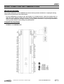
IMPORTANT WARNING
Any wiring modification on the CLIMATIC 50 must be done by Lennox technician or employees having
valid electrical qualification and authorisation.
For any modification of wiring on the 24V supply or on 4-20mA sensor, check the polarity prior to
apply the power. Wrong polarity may cause serious damage and destroy the Plan network. Lennox
will not accept liability for damage caused by wrong power connection or any wiring modification
done by people without valid training and qualifications.
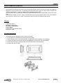
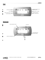
CONNECTION DIAGRAM
CLIMATIC™ 50 CONTROLLER
CLIMATIC 50 user manual – Chillers ranges
CL50-CHILLERS/IOM/1105-E
33
WIRING CONNECTIONS AND COMMUNICATIONS
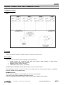
CONNECTION DIAGRAM
CLIMATIC 50 CONTROLLER - OPTION DC50 REMOTE CONNECTION
CLIMATIC 50 user manual – Chillers ranges
CL50-CHILLERS/IOM/1105-E
44
WIRING CONNECTIONS AND COMMUNICATIONS
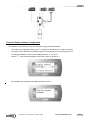
COMMUNICATION
BMS
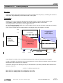
Function
This is used to link a Climatic to a BMS network for remote control of the unit.
Description
The Climatic 50 can communicate according to various protocols:
1. Climatic protocol for connection with KP06 (see specific KP06 manual) or other Lennox
communication products (3932 = Climatic)
2. MODBUS Protocol (3932 = Modbus)
3. LONWORKS system (3932 = LonWorks)
MODBUS and LONWORKS address table are given at the end of this manual.
The identification number of each unit can be set (3931) and the communication speed is adjustable
between 1200Bds and 19200Bds (3933).
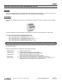
MODBUS protocol
For this option the BM50 must be equipped with the board, PCO1004850
This card is used to interface BM50 to an RS485 network.
The card guarantees the optical isolation of the controller from the RS485 serial network.
CLIMATIC 50 user manual – Chillers ranges
CL50-CHILLERS/IOM/1105-E
55
On the Climatic, set point 3932 = ModBus
Transmission Mode = RTU
Baud Rate = set point 3933 (1200 / 2400 / 4800 / 9600 / 19200)
Word Length = 8
Parity = NONE
Stop Bits = 2
Device Id = set point 3931 (1 to 200)
LONWORKS protocol
For this option the BM50 must be equipped with the board, PCO10000F0
This card is used to interface BM50 to a LonWorks® network, by FTT-10A 78 kbs (TP/FT-10).
On the Climatic, set point 3932 = LonWorks
Baud Rate = set point 3933 (4800)
Device Id = set point 3931 (1 to 200)
Application
Normally the Climatic work on its calendar zones of operation (Zone A, B, C, Unoccupied).
Warning: The points in writing received from the BMS are taken into account by Climatic only if mode BMS
is activated ("Watchdog", address 3934)
The BMS mode is activated if the watchdog is different from zero (DS50 address 3934, Modbus analogical
item1, Lonworks address I_Sp_BMS_Dog).
Every second, the Climatic 50 decreases the value of this address by 1. If this address reaches zero, then
the Climatic 50 works as a stand alone unit in order to check continuously the communication with BMS.
Normally, the BMS has to send a value to this address regularly (example 255 every 4 mn).
CLIMATIC 50 user manual – Chillers ranges
CL50-CHILLERS/IOM/1105-E
66
WIRING CONNECTIONS AND COMMUNICATIONS
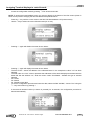
COMMUNICATION
MASTER/SLAVE
Function
Link several units in order to allow a “Master/Slave” relationship in between each units
Description
Three modes are available and can be set up using following set points:
3922 Æ number of units linked (maximum 4 for Ecologic range, 2 for Ecomax)
3923 Æ Operation mode:
•
Back-up mode
One unit is the back-up unit and will operate if any of the other units has a failure.
•
Rolling Back-up mode
Same as above, except the "back-up" unit will change every Tuesday.
•
Cascade mode
No back-up unit. During start-up, the units’ capacity steps are started in cascade unit by unit.
In every case, the outlet water temperature (set point 3924) and/or the outside air temperature (set point 3925) used for
regulation can be set by using following calculations:
•
Not used
Æ Each unit regulates with its own sensors
•
M/S Temp
Æ Slaves units regulate with Master sensors
•
M/S Aver
Æ Every units regulate with the global sensors average value
In every mode, for the management of safety, each unit remains independents.
CLIMATIC 50 user manual – Chillers ranges
CL50-CHILLERS/IOM/1105-E
77
LAN configuration
On the LAN network, each unit needs to be addressed:
•
Unit n°1
Æ Master unit
•
Unit n°2 to 4
Æ Slave units
For the configuration of each unit address on the LAN network, refer to DS50 Service display chapter.
Page 53 and above
Each DC 50 has to be addressed to its correspondent unit. In order to do so, please refer to DC50 Comfort Display page 43 and
above.
Both operations must be done without network connection (connector J11 on BM50).
If a unit has electronic expansion valves, the driver address must be corrected as explained in the correspondent chapter page
20 and above.
CLIMATIC 50 user manual – Chillers ranges
CL50-CHILLERS/IOM/1105-E
88
SCHEDULING
Function
Controlling operation of the unit according to the time and day
Description
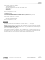
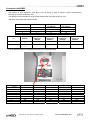
CLIMATICTM 50 can handle 4 time zones over the 7 days of the week:
• Zone unoccupied
• Zone A
• Zone B
• Zone C
Starting time (hours and minutes) of each of these zones for each days of the week, can be set using menus
3211 to 3214, (press PROG key to change day).
3211 Æ Starting time Unoccupied Zone (hour,minute)
3212 Æ Starting time Zone A (hour,minute)
3213 Æ Starting time Zone B (hour,minute)
3214 Æ Starting time Zone C (hour,minute)
8h00
Unoccupied
Monday
12h00
ZA
14h00
ZB
20h00
ZC
Unoccupied
Tuesday
Wednesday
Thursday
Friday
Saturday
Sunday
For each time zone the following set points can be adjusted:
.
1. Pump control type. Set point 3112, (refer to the “pump control” pages for more details).
2. Change Over rules for heat pump units. Set point 3311 must be set for each time zone
3. Heating and cooling temperature set points. Set point 3321 to 3325 for cooling and 3331 to 3335 for
heating (refer to the control set point pages for more details)
4. Compressor operation. Set point 3411 (refer to the compressor operation pages for more detailed
information)
With DS50, for each set point, press PROG key to change time zone and validate the right set point in the
right zone
Note: “Monday” is the first day of the week for the scheduling on CLIMATICTM 50
As a factory setting, only Zone A is activated 24hours a day, 7 days a week
CLIMATIC 50 user manual – Chillers ranges
CL50-CHILLERS/IOM/1105-E
99
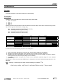
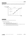
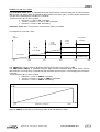
ANTICIPATION – Heat pump mode only
Function
This allows an anticipated start-up in the morning depending on the outdoor temperature.
Description
This function only works for zone A, and allow the machine to move from unoccupied zone to zone A earlier if
the outdoor temperature is under a certain value.
This will allow the unit to anticipate a cool day.
This can be adjusted with set point 3221 and 3222.
3221 Æ bottom of the slope (°C), Anticipation starting point .
3222 Æ Slope in Minutes of anticipation per degrees
Example:
WA chiller with Zone A
starting at 8.00 am
3221 set at 3°C
3222 set at 10mn/°C
Zone A starting
time
If outside temperature is
0°C, the zone A will start
at 7.30 am
7.30 am
Outside air
temp
8.00 am
0°C
CLIMATIC 50 user manual – Chillers ranges
3°C
CL50-CHILLERS/IOM/1105-E
1010
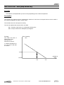
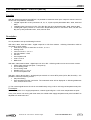
CHANGE OVER – REVERSIBLE UNITS
Function
For Reversible units only. This allows the reversible units to change automatically from winter to summer
operation.
Description
This function will change the unit from production of hot water to production of chilled water automatically and
can be set up with following set points:
3311 Æ Change over mode according to following values
Cool. Only
Æ cooling only
Heat. Only
Æ heating only
Auto.
Æ Automatic change over - pumps are running in dead zone
Auto. Stop
Æ Automatic change over – pumps are stopped in dead zone
3312 Æ Change over winter setting
The set point 3312 is the outside air temperature under which the unit will operate as a heat pump.
3313 Æ Change over summer setting
The set point 3313 is the outside air temperature over which the unit will operate as a chiller.
Example:
Chiller operation
Dead zone
Heat pump operation
3312 = 12°C
3313 = 23°C
12°C
CLIMATIC 50 user manual – Chillers ranges
23°C
Outside air temp
CL50-CHILLERS/IOM/1105-E
1111
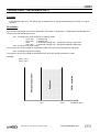
EVAPORATOR PUMP(S) CONTROL
Function
Ensure the presence of a flow rate of heat transfer fluid in the evaporator heat exchanger.
Description
Seven types of control rules can be set. They are defined using the menu 3112 on the DS50 Service
Display.
• If 3112 = Started .........................CLIMATICTM 50 does not control the pumps
• If 3112 = Stopped, ......................Pumps are stopped.
• If 3112 = P1 Only .........................CLIMATICTM 50 Control only runs pump n°1.
• If 3112 = P2 Only ........................CLIMATICTM 50 Control only runs pump n°2.
• If 3112 P1N P2R ..........................CLIMATICTM 50 Control handles both pumps with
N°1 as standard and N° 2 as backup.
• If 3112 = P2N P1R ......................CLIMATICTM 50 Control handles both pumps with
N°2 as standard and N° 1 as backup.
• If 3112 – Clock .............................CLIMATIC™ 50 control handles both pumps equalizing running
times and switching from one pump to the other every Tuesday at
18h00.
This
Pump N°1 is running if all of the following conditions are met:
Ö At least one ON/OFF of circuit “n” is ON
Ö Unit remote ON/OFF is ON *
Ö NOT in the unoccupied zone*
Ö Set point 3112 is not set to “Stopped”
Ö Configuration 3841 is not set to “No”
Ö Pump has been stopped for 1 minute or is already running.
Ö There is no electrical fault on the pump
Ö There is to « flow rate » fault
* These conditions are ignored if the outdoor temperature is below set point 3341 + 1°C and if the outlet
water temperature is below set point +1°C, in order to prevent the water from freezing.
A pump can be controlled by the CLIMATICTM50 even if electrically the network pump is not handled by the
refrigeration unit.
In the case where the customer is handling the control of his own pump, the following procedure must be
followed:
Start the pump at least 1 minute before validating the remote ON/OFF switch operation.
Switch off the pump 2 minutes at least after the remote ON/OFF switch has gone to 0.
CLIMATIC 50 user manual – Chillers ranges
CL50-CHILLERS/IOM/1105-E
1212
In the case of double pumps
The pump N°k is running if all of the following conditions are met:
Ö The conditions detailed above for the single pump must be met for the pump k
Ö In the case of forced operation, pump N°k is running (set point 3112 is set to “P1 Only” for pump N°1 and
“P2 Only” for Pump N°2)
Ö When running « Standard/Backup » Operation, pump N°k has priority (Set point 3112 set to “P1NP2S” for
Pump N°1 and “P2NP1S” for pump N°2).
Ö In the case of “equalized run time” operation the running time of pump N°k is the smallest
In case of a fault on a pump when the set point 3112 is set to « P1NP2S », « P2NP1S » or « Clock », the
second pump, if available, will automatically start.
NOTE:
CLIMATICTM 50 control only stops the pumps 2 minutes at least after the request to switch the
whole unit OFF has been given, in order to prevent any risks of freezing the evaporator heat
exchanger.
CLIMATIC 50 user manual – Chillers ranges
CL50-CHILLERS/IOM/1105-E
1313
THERMOSTAT – Set point calculation
Function
Set the chilled or hot water circuit temperature, depending on the outdoor conditions in order to optimise the
energy consumption.
Description
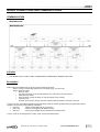
Calculation of the chilled water set point :
Calculated
Set Point
Values are given for indications only.
Gradient can be positive or negative.
3321
10°C
3322
Outdoor
Temperature
7°C
3323
22°C
3324
30°C
Calculation of the chilled water set point:
²
Values are given for indications only.
Gradient can be positive or negative.
Calculated
Set Point
3331
40°C
3332
30°C
3334
0°C
CLIMATIC 50 user manual – Chillers ranges
3333
19°C
Outdoor
Temperature
CL50-CHILLERS/IOM/1105-E
1414
THERMOSTAT - Control principle
Function
Adjust and hold the fluid outlet temperature as close as possible to the set point, by controlling the number of
compressor stages depending on the thermal load on the system.
Description
CLIMATICTM50 control constantly calculates the required capacity to reach the temperature set point.
This variable is called “CAPACITY FACTOR” (CF) and its value can vary from 0 to 100%.
It is directly linked to the number of control stages of the unit.
i.e.: For ecologic WA 230D K STD with 6 control stages, the CF will start and stop a stage at the following
values:0-17-33-50-67-83-100
It then evolves following the principles detailed in the diagram below (This applies to a chiller):
+ 2°K
CF FROZEN
1°K
++ 2°C
Difference
between
Water outlet
Temperature
and SET POINT
CF INCREASES
(Start more
Capacity Stages)
Zone
A
0°K
A
CF DECREASES
(Removes
Capacity Stages)
- 1°K
CF FROZEN
- 2°K
FAST
SLOW
Water Outlet Temperature
Change Rate
SLOW
FAST
In any Cases, for a chiller, if the Low Water temperature limit is reached, Compressors are stopped.
In order to anticipate, the reference point is recalculated each time the difference between water temperature
and set point reach a minimum or a maximum.
The rate of change of the Capacity Factor (CF) is determined by another parameter called “REACTIVTY”
and which value is in:
% of CF / °C (Diff vs Set point) / min
REACTIVITY for Cooling Mode can be adjusted in menu 3325
REACTIVITY for Heating Mode can be adjusted in menu 3335
CLIMATIC 50 user manual – Chillers ranges
CL50-CHILLERS/IOM/1105-E
1515
COMPRESSOR CONTROL
Function
Compressor stages are started and stopped in a pre-determined order which minimized the effect of the
« anti- short cycle protection and equalized running time.
Description
) Compressor Starting and Stopping Sequences
This Sequence is determined by the calculated compressor running time. This control also includes the
automatic and instantaneous back up of a compressor by another one if it becomes unavailable.
) Starting and Stopping Compressors
Compressor XXX starts if all the following conditions are met :
Ö The water circulation pump has been running for at least 1 minute.
Ö Remote ON/OFF switch for the complete unit is ON
Ö The ON/OFF control for the considered circuit is ON
Ö The unit, the compressor and the circuit do not have any “Majors Alarm” ON
Ö The control requires the start-up of a compressor.
Ö XXX is the compressor with the lowest run time amongst the stopped compressor. To see the run times
for each compressor refer to menu: 2419, 2429….2469
Ö Compressor XXX was not started for at least 6 minutes. The state of each compressor can be checked in
the following menu: 2412, 2422, 2432…, 2462
CLIMATIC 50 user manual – Chillers ranges
CL50-CHILLERS/IOM/1105-E
1616
HIGH PRESSURE UNLOADING
Function
Reduce the capacity of a refrigeration circuit before the HP cut out is reached
Description
High Pressure Unloading consists in reducing the variable capacity on a screw compressor, or to stop one
compressor on units fitted with tandems or trios.
) Activation of High Pressure Unloading
If High Pressure is over 26.5 bars (Ecologic, MCC with scroll compressors) or 23.5 bars (other units) and
carries on increasing as all the fans are running full speed, one compressor is stopped, or one stage of
capacity reduction is activated on the affected circuit.
High Pressure Unloading is controlled as an additional virtual ventilation stage while the HP is over the
threshold. See explanation in the fan control section.
CLIMATIC 50 user manual – Chillers ranges
CL50-CHILLERS/IOM/1105-E
1717
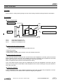
DEFROST – Heat Pump
Function
Avoid the ice on the Evaporator while the reversible unit works in winter operation
Description
To avoid the icing of the external air exchanger in winter operation, it is necessary to reverse the refrigerant
cycle on a regular basis to de-ice by heating the exchanger.
The defrost is activated when the air temperature is under a set point (3432) and the LP is lower than a set point
(3433)
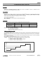
While defrost is demanded, the defrost cycle is as following:
1.
2.
3.
4.
5.
6.
7.
8.
9.
Stop compressor and fans
wait 5s
reverse 4 way valve
wait 5s
start compressor
When HP reach 22b or compressor are running for more than 4 minutes, stop compressor
wait 5s
reverse 4way valve
start fans at full speed in order to dry the exchanger for a period that can be adjusted with
set point 3435.
10. end of defrost
Two different type of Defrost demand are possible:
• Dynamic defrost (set point 3431 = Dynamic)
• Cycling defrost (set point 3431 = Cyclic)
CLIMATIC 50 user manual – Chillers ranges
CL50-CHILLERS/IOM/1105-E
1818
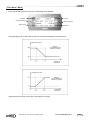
Dynamic defrost
This allows the unit to start the defrost cycle only when required. This is achieved through the measurement of the temperature
difference between the coil and the outdoor. The defrost will be initiated shortly after the Climatic50 has located the largest
gradient in the curve.
Temperature difference
between coil and
outdoor
Coil
clean
Coil freezing
Coil
frozen
Defrost cycle start
Highest gradient
Time
Cycling defrost
The unit will start a defrost cycle with a regular time period (set point 3434)
Defrost parameters summary:
3431 Æ
3432 Æ
3433 Æ
3434 Æ
3435 Æ
Defrost mode: dynamic – cyclic
Outside air temperature under which the defrost cycle is activated
LP temperature under which the defrost cycle is activated.
For the dynamic defrost the unit will run this minimum amount of time. For cycling defrost, this is the time
delay to start the defrost once the temperature conditions are met
Fan running time after the defrost cycle in order to dry the exchanger.
CLIMATIC 50 user manual – Chillers ranges
CL50-CHILLERS/IOM/1105-E
1919
DRIVING THE ELECTRONIC EXPANSION VALVE
Function
Control the adequate filling of the evaporator heat exchanger with refrigerant, in order to get the best
efficiency, while allowing a good protection of the compressor against liquid slugging
Description
The electronic expansion valves used on units fitted with CLIMATICTM 50 are controlled using the EVD200
Driver
This driver is design to communicate with the CLIMATICTM 50 main control board through a “pLan” BUS.
The driver can be set up using the following DS50 menus:
3511, 3521, 3531, 3541 Æ Superheat circuit 1, 2, 3, 4
3512, 3522, 3532, 3542 Æ Anticipation circuit 1, 2, 3, 4
3513, 3523, 3533, 3543 Æ Proportional Factor circuit 1, 2, 3, 4
3514, 3524, 3534, 3544 Æ Integral Factor circuit 1, 2, 3, 4
3515, 3525, 3535, 3545 Æ Derivative Factor circuit 1, 2, 3, 4
It is highly recomended NOT TO CHANGE the factory setting of the EVD Driver
The Anticipation factor allow the pre-opening of the EEV during circuit start-up and is calculated according to
the capacity at start up.
Futhermore the EVD Driver is fitted with Leds indicating its status:
Power (Green)
Open (Green)
Æ
Æ
Close (Green)
Æ
Error (Red)
pLan (Green)
Æ
Æ
Shows the power is ON
Flashes during the expanion valve Opening –
Stays ON when the expansion valve is Fully Open.
Flashes during the expanion valve Closing –
Stays ON when the expansion valve is Fully Closed.
Stays ON when Alarm is ON (Refer to Faults and Alarms section)
Stays ON when the communication is established with CLIMATICTM 50 –
Flashes when the communication is disturbed or broken.
CLIMATIC 50 user manual – Chillers ranges
CL50-CHILLERS/IOM/1105-E
2020
Connexion with BM50
The address of each expansion valve driver must be set-up in order to ensure a good communication
between the Climatic 50 and the diver.
The address can be changed by using the dip switches that are under the Driver cover.
Addresses must follow the rules hereunder:
Ecologic n°
BM50 address
1
2
3
4
1
2
3
4
Ecomax
n°
BM50
address
1
1
2
3
4
2
Driver circuit
n°1 address
5
7
9
11
Driver circuit
n°2 address
6
8
10
12
Driver
circuit n°1
address
5
Driver
circuit n°2
address
6
Driver
circuit n°3
address
7
Driver
circuit n°4
address
8
9
10
11
12
The dip switches have to be positioned according to the following table:
Weight
Address\
5
6
7
8
9
10
11
12
SW1
1
SW2
2
SW3
4
SW4
8
SW5
16
ON
OFF
ON
OFF
ON
OFF
ON
OFF
OFF
ON
ON
OFF
OFF
ON
ON
OFF
ON
ON
ON
OFF
OFF
OFF
OFF
ON
OFF
OFF
OFF
ON
ON
ON
ON
ON
OFF
OFF
OFF
OFF
OFF
OFF
OFF
OFF
CLIMATIC 50 user manual – Chillers ranges
CL50-CHILLERS/IOM/1105-E
2121
CONDENSING FANS CONTROL
Function
Maintain the condensing pressure as stable and as low as possible in order to increase the unit
performances, while avoiding excessive cycling.
Description
Identical to the complete machine control logic, the CLIMATICTM 50’s aim is to reach and hold the high
pressure set point. However the fan control includes a dead zone ensuring a greater stability to the High
Pressure and avoiding starting and stopping the fans too frequently.
Can be adjusted using menus
3611 = High pressure control set point in bars (relative pressure)
3612 = Reactivity
Operation
On a unit with N fans per circuit, the number of stages follows the table hereunder:
Model
WA/RA
STD/HE/SLN
WA LN
Where:
PV with PWM
Number of Stages
PV
GV
1
0
N-1
1
N-1
0
PV: Low speed Fan Operation
GV: High Speed Fan Operation
PWM: Pulse Width modulation (only on PV)
CASE 1 Unit without PV or PWM
The Ventilation Factor “V.F.” is calculated using the evolution of High Pressure (measured using the HP
sensor) and the rate at which it is moving away or towards the High Pressure Set Point (3611). See diagram
page 12.
It also includes a dead zone of 5 bars (4 bars if the unit has glycol and water set point <0°C) and a sampling
time constant of 15 seconds.
As for capacity control, the reactivity will fasten or slow down the VF evolution
Example: Unit with 3 fans, one circuit and HP set point 3611 is set to 15 bars
Pressure > 15 bars Æ V.F. increasing
10 bars < Pressure < 15 bars Æ V.F. unchanged
Pressure < 10 bars Æ V.F. decreasing
Ventilation Factor
100%
Circuit
unloading
75%
V3 GV
50%
V2 GV
25%
V1 GV
Nothing
CLIMATIC 50 user manual – Chillers ranges
CL50-CHILLERS/IOM/1105-E
2222
CASE 2 Unit with PV or PWM
The Ventilation Factor “V.F.” is calculated using the High Pressure measured using the HP sensor and the
rate at which it is moving away or towards the High Pressure Set Point (3611). It also includes a dead zone
of 5 bars and a sampling time constant of 15 seconds.
If menu set point 3611 is set to 15 bars
Pressure > 17 bars Æ V.F. increasing
12 bars < Pressure < 17 bars Æ V.F. unchanged
Pressure < 12 bars Æ V.F. decreasing
Ventilation Factor “V.F.” can be seen in menu 2222 to 2225 on the DS50
For example on a unit with 3 Fans
Fan
Stages
Compressor
unloading
V2 GV
V3 GV
V1 GV
V2 GV
V3 GV
V1 PV PWM
V2 GV
V1 PV PWM
V1 PV PWM
Ventilation factor
0%
20%
40%
60%
80%
100%
The “PWM factor” which is used to adjust the speed of the fan when it is running in PWM
This PWM Factor “PWM.F” is calculated using the High Pressure measured using the HP sensor and the
rate at which it is moving away or towards the High Pressure Set Point (3611). The sampling time constant is
5 seconds.
If menu set point 3611 is set to 15 bars
Pressure > 15 bars Æ PWM.F. increasing
14 bars < Pressure < 15 bars Æ PWM.F. unchanged
Pressure < 14 bars Æ PWM.F. decreasing
PWM Factor
100%
0%
0%
Speed in % of max PV
100%
Value for PWM.F can be seen on menu 2619, 2629, 2639 and 2649 on a DS50
CLIMATIC 50 user manual – Chillers ranges
CL50-CHILLERS/IOM/1105-E
2323
CUSTOMIZED INPUT / OUTPUT (BE.50)
Function
With the optional expansion board BE.50, it is possible to customize some input / output for remote control of
the unit. So it is possible to customize:
• 4 digital outputs NC or NO (connectors J5, J6, J7, J8) set up with parameters 3851, 3852, 3853 and
3854
• 4 digitals inputs (connectors J4 ID1, ID2, ID3, ID4) set up by parameters 3861, 3862, 3863 et 3864
• 4 analogical inputs (4-20mA or Lennox NTC temperature probe on connectors J9 B1, B2, B3 and
B4), set up with parameters 3871, 3872, 3873 et 3874
Description
So it is possible to set up the following functions:
With 3851, 3852, 3853 and 3854 - digital output NC or NO free contacts - following information could be
recovered on each contact:
• Fault fans or pumps or water flow or Cicuit1, 2, 3 or 4.
• Heating mode
• 100% on Circuit 1, 2, 3 or 4
• Unit fully loaded – 100%
• Unit ON
• Unoccupied mode
• zone A, B ou C
• BMS mode
With 3861, 3862, 3863 et 3864 - digital input 24V AC or DC – following orders can be sent on each contact:
• Switch water set point (set point 1 / set point 2)
• Force Heating mode
• Force cooling mode
• Disable circuit 1, 2, 3 or 4.
• Force unoccupied mode
With 3871, 3872, 3873 et 3874 – analogical input 4-20mA or Lennox NTC probe (J9 B1, B2, B3 et B4) – It is
possible to make the following actions:
• Set point offset(*)
• Free temperature probe connection. The measured value will be displayed on following addresses
2191, 2192, 2193 or 2194.
(*) The 4-20mA signal sent to the unit is converted linearly using a -5K to +5K range of temperature set point.
For example:
For a unit set point of 7°C supply temperature, a 20mA signal will give a 12°C return temperature set point.
In any case, with a unit running with clear water, the chilled water supply temperature set point CAN NOT be
adjusted to a value below 6°C.
CLIMATIC 50 user manual – Chillers ranges
CL50-CHILLERS/IOM/1105-E
2424
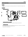
FREE-COOLING
Function
Ensure optimum cooling capacity though the use of free cooling, therefore reducing electrical consumption.
Description
) Free-cooling principle
3 Way
TEE
FANS
TEA
Eva
Free cooling coil
TSE
TEE Ù
TSE Ù
TEA Ù
Inlet water temperature (°C)
Outlet water temperature (°C)
Outdoor air Température (°C)
) Control of the free-cooling 3 way valve
3 way valve is activated if the following conditions are met.
Ö The unit is running
Ö TEA is below the TEE.
Ö Chilled water circulation pump has been running for at least 30 seconds
) Control of the free-cooling fans
In the case where the free cooling fans are the same as the main refrigeration circuit fans, (which is the most
popular mode for Lennox units), they are constantly running if the compressors are stooped and if the chilled
water outlet temperature is above the set point defined in menu 3321 and 3322.
When a compressor starts, the fans run as without free-cooling.
In the case where the free cooling fans are independent from the main refrigeration circuit fans, they are
running for as long as the chilled water outlet temperature has not been reaching the set point defined in
menu 3321 and 3322.
) Compressor Operation
For the compressor control, if the outside temperature is lower than the water entry temperature, the freecooling is considered as an additional first compressor stage by the regulation.
CLIMATIC 50 user manual – Chillers ranges
CL50-CHILLERS/IOM/1105-E
2525
ENERGY RECOVERY
Function
Ensure optimum cooling capacity by improving the performance of air cooled chiller with energy recovery
system
Description
) Energy recovery Principle
2
7
Water condenser
for energy
recovery
2
7
Air cooled
condenser
) Activation of the energy recovery function
The energy recovery function on the Chiller is activated by switching the menu 3843 to “ON”
) Condenser fans control
When switching to energy recovery mode (Activation of the flow switch + 5s) the fans of the considered
circuit are stopped by forcing the fan’s capacity factor to 0%.
Then the fans are controlled as usual
CLIMATIC 50 user manual – Chillers ranges
CL50-CHILLERS/IOM/1105-E
2626
FAULT
CODES
CLIMATIC 50 user manual – Chillers ranges
CL50-CHILLERS/IOM/1105-E
2727
FAULT CODES
CHILLED WATER TEMPERATURE, OUT OF RANGE
Fault Code: 012, 013, 022, 023
Description
Water Inlet or Outlet Temperature measured by the temperature sensor is outside the authorised range, this
range can vary depending on the presence or not of glycol with the chilled water (factory setting)
TE < set point 3341 (chilled water min set point) or TE > set point 3342 (Hot water max set point)
TS < set point 3341 (chilled water min set point) or TS > set point 3342 (Hot water max set point)
Where:
TE
TS
3341
3342
Ù
Ù
Ù
Ù
Water inlet Temperature (°C)
Water outlet Temperature (°C)
Minimum chilled water Temperature at evaporator (°C)
Maximum chilled water Temperature at evaporator (°C)
Action
) Compressor immediate shutdown
) A fault signal is shown on the display.
• 012, Outlet water T° too high
• 013, Intlet water T° too low
• 022, Outlet water T° too low
• 023, Intlet water T° too high
) The remote fault signal is delayed by 6 minutes
Reset
Automatic reset of the fault signal as soon as the chilled water temperatures comes back in the authorized
operating range with a safety offset of 2°C on the chilled water and 5°C on the hot water.
Water
Set point 3341+2°C < TE < set point 3342 -5°C
Set point 3341+2°C < TS < set point 3342 -5°C
Possible causes
Faulty Chilled water inlet or outlet temperature
probes
Wiring problem with the probes, disconnect the
sensor.
CLIMATIC 50 user manual – Chillers ranges
Solving the problem
Replace the probe.
Check the probe connections.
CL50-CHILLERS/IOM/1105-E
2828
FAULT CODES
INSUFFICIENT WATER FLOW RATE
Fault Code: 001
Description
The flow switch FSE is detecting a low water flow rate in the evaporator heat exchanger for more than 3
seconds
Action
) Immediate shutdown of the whole unit.
) A fault signal is shown on the display.
) The remote fault signal is delayed by 6 minutes
Reset
The unit restarts automatically, 20 seconds after the flow switch detects a flow rate.
Possible causes
Problem with the pump control wiring.
Problem with the flow switch wiring
Dirty or clogged water filter.
Wrong setting of the flow switch.
CLIMATIC 50 user manual – Chillers ranges
Solving the problem
Check the pump connections
Check the flow switch connections
Clean the water filter.
Check the flow switch settings.
CL50-CHILLERS/IOM/1105-E
2929
FAULT CODES
COMMUNICATION WITH THE EXTENSION BOARD
Fault Code: 071
Description
The communication between the BM50 and the BE50 is down.
Action
Alarm signal is ON
The unit carries on running
Reset
The fault signal disappears automatically as soon as the communication is back on line.
Possible causes
Damaged BM50 or BE50
Bios mal function
Wrong wiring or loose connection between BM50
and BE50
CLIMATIC 50 user manual – Chillers ranges
Solving the problem
Replace the defective component
Update Bios up V3A.57 or 3.64 and above
Check connections and wiring.
CL50-CHILLERS/IOM/1105-E
3030
FAULT CODES
LOW PRESSURE CUT OUT
Fault Code: 1n7
Description
The low pressure cut out limit depends on the type of refrigerant which is inside the circuit and is defined as
following:
R407C Ö 1,5 bar abs. (Or –28°C Vapour Saturated Temperature).
One compressor on circuit n does not work for 2 minutes and in the case of a unit with low ambient kit and
Thermostatic Expansion Valve, the TXV bypass valve has been closed for 1 minute, but the low pressure is
too low.
NOTE:
Only units with thermostatic expansion valves and Low ambient kit options are fitted with TXV
bypass.
Action
)
)
)
)
If the Low Pressure of a circuit is below the safety limit for more than an hour, then the considered
circuit is not allowed to start again.
This circuit is shut down immediately.
A fault signal is shown on the display.
The remote fault signal is delayed by 6 minutes.
Reset
Automatic reset of the fault signal as soon as the low pressure moves above the “CUT OUT” limit
If the low pressure fault is activated more than three times during the same day, the fault signal is locked out
and must be reset manually.
The auto reset limits are detailed below
R407C Ö 2.5 bars abs. (or –16°C saturated vapour temperature).
Note:
Fault counter is cleared and reset every day at 10 am, as long as the maximum number of faults
has not been reached.
Possible causes
Not enough refrigerant in the circuit.
Faulty expansion valve.
Dirty filter drier.
Faulty low pressure sensor.
CLIMATIC 50 user manual – Chillers ranges
Solving the problem
Adjust the refrigerant charge
Check the good working of the expansion valve.
Change the filter drier
Replace the low pressure sensor.
CL50-CHILLERS/IOM/1105-E
3131
FAULT CODES
EVAPORATOR FREEZING PROTECTION
Fault Code: 1n8
Description
This fault signal is activated on units chilling water without frost protection additives (Water without Glycol or
Brine) and with thermostatic expansion valves.
One compressor from the considered circuit n has been running for at least 2 minutes and the saturated
temperature TBPn is lower than the set point 3421 for more than 5 seconds (for units filled with R407c).
This safety feature is disabled for 2 minutes after start-up or stop of a compressor or a fan on the considered
circuit.
With:
TBPn
Ù
Evaporating Temperature of circuit n - dew point (°C)
3421
Ù
Minimum Evaporating Temperature (°C)
Action
) Immediate shutdown of circuit n
) Fault signal sent to the control display.
) The remote fault signal is delayed by 6 minutes
Reset :
The first 3 faults are automatically reset
After three faults the circuit n can only be restarted by a manual reset
Note:
Fault counter is cleared and reset every day at 10 am, as long as the maximum number of faults has not
been reached.
Possible causes
Faulty LP pressure sensor
Faulty wiring or loose sensor connection.
Insufficient water flow rate in the evaporator.
Clogged evaporator
Check set points
CLIMATIC 50 user manual – Chillers ranges
Solving the problem
Replace the pressure sensor.
Check pressure sensor connections and wiring.
Check flow rate and adjust flow switch if necessary.
Clean evaporator.
Replace pressure sensor.
CL50-CHILLERS/IOM/1105-E
3232
FAULT CODES
FAULTY PROBES AND SENSORS
Fault Code: 081, 083, 086, 087, 089, 1n1, 1n2, 2n6
Description
One or more temperature probes or pressure sensors located on circuit n or elsewhere are short circuited,
cut or disconnected.
Probe or sensor affected by the problem
Water inlet temperature probe Æ code 081
Water outlet temperature probe Æ code 085
Air temperature probe Æ 083
Heat recovery exchanger inlet temperature probe Æ code 086
Heat recovery exchanger outlet temperature probe Æ code 087
High Pressure Sensor Æ Code 1n1
Unit without EEV
Low Pressure Sensor Æ Code 1n2
Unit with EEV
Low Pressure Sensor or suction probe Æ Code 2n6
Action
)
)
)
)
)
Immediate shut down of circuit n for faulty sensors.
Immediate shut down of ALL circuits for faulty water outlet temperature and air temperature probes.
No shut down for the other faults.
Fault signal shown on the display.
The remote fault signal is delayed by 6 minutes.
Reset
The unit returns to normal operation after the signal from the faulty probes or sensors is re-established.
Possible causes
Damaged probes or sensors
Wrong wiring or loose connection on a probe or
sensor
CLIMATIC 50 user manual – Chillers ranges
Solving the problem
Remplace probe or sensor
Check probes and sensors connections and
wiring.
CL50-CHILLERS/IOM/1105-E
3333
FAULT CODES
COMPRESSOR ELECTRICAL PROTECTION
Fault Code: 1n4
Description
During start up or operation of a compressor m:
• The thermal magnetic trip breaker or the compressor internal protection from circuit n is tripped
• The phase rotation protection has detected an incorrect connection (standard on screw compressor and
available as a special request on other units)
• The discharge line thermostat is tripped out (screw compressors only)
Action
) Immediate shut down of compressors m from circuit n.
) Fault signal shown on the display.
) The remote fault signal is delayed by 6 minutes.
Reset
If the fault signal comes from the internal compressor protection, it can be automatically reset. In this case,
Climatic 50 will restart the concerned circuits 30 minutes after shutdown.
After three automatic reset of the compressor fault signal, the circuit n can only be restarted by a manual
reset of the fault signal.
Important: For manual reset of ZR 380 internal protection cut off; if the problem comes from a high
discharge temperature, wait for 30 mn prior to any manual reset to allow the scroll temperature to decrease
sufficiently. If the temperature is still too high, the compressor will trip again just after starting.
Notes:
Fault counter is cleared and reset every day at 10 am, as long as the maximum number of faults has not
been reached.
The fault signal is reset automatically with each powering of the unit
Possible causes
Wrong wiring or tightening of the connections.
Wrong setting on the circuit breaker
CLIMATIC 50 user manual – Chillers ranges
Solving the problem
Control all connections
Set circuit breaker according with compressor
normal running current
CL50-CHILLERS/IOM/1105-E
3434
FAULT CODES
HIGH PRESSURE TOO HIGH
Fault Code: 1n5
Description
High pressure switch from circuit n has tripped.
Action
) Immediate shut down of circuit n.
) Fault signal shown on the display.
) The remote fault signal is delayed by 6 minutes
Reset
The first 3 faults are automatically reset
After three faults the circuit n can only be restarted by a manual reset
Notes:
Fault counter is cleared and reset every day at 10 am, as long as the maximum number of faults has not
been reached.
Possible causes
Dirty condenser.
Wrong setting on the condenser control.
Wrong operation of the liquid line solenoid valve
Fan out of order
Wrong wiring or wrong setting of the high
pressure, pressure switch.
Dirty Filter Drier
CLIMATIC 50 user manual – Chillers ranges
Solving the problem
Clean the condenser.
Check the settings of the controller.
Check the operation of the solenoid valve.
Change the fan
Check the wiring and the setting of the HP
switch.
Change the filter drier.
CL50-CHILLERS/IOM/1105-E
3535
FAULT CODES
INSUFFICIENT FLOW RATE PROVIDED BY THE PUMP
Fault Code: 001 040
Description
Pump k supplying flow rate to the evaporator has been ordered to start for 20 seconds.
The flow switch FSE is detecting insufficient flow rate in the heat exchanger for more than 25 seconds.
Action
Case 1 :
The unit only handles ONE pump
) Immediate shut down of compressors and pump k.
) Fault signal 001 is shown on the display.
) The remote fault signal is delayed by 6 minutes
Case 2 :
The unit handles TWO pumps and the “Normal/ Safety” mode or “Clock” has been activated.
) Immediate shut down of pump k.
) Start up of the 2nd pump (refer to “EVAPORATOR PUMP(S) CONTROL” section for more details)
) If the FSE is detecting a flow rate, then the fault 040 is shown on the display, the unit is then running
normally
) If the FSE does not detect any flow rate the fault 040 is shown on the display, the unit is then shut down
) The remote fault signal is delayed by 6 minutes
Reset
In all cases implying a shut down of the unit, 3 start up attempts are made then after these three faults per
day the unit can only be restarted by a manual reset
Notes:
Fault counter is cleared and reset every day at 10 am, as long as the maximum number of faults has not
been reached.
Possible causes
Problem in the pump control wiring.
Problem with flow switch wiring.
Dirty water filter
Wrong setting of the flow switch
CLIMATIC 50 user manual – Chillers ranges
Solving the problem
Check the pump connections
Check the flow switch connection
Clean the water filter
Adjust the setting of the flow switch
CL50-CHILLERS/IOM/1105-E
3636
FAULT CODES
FAN(S) CIRCUIT BREAKER(S) OPEN
Fault Code: 90, 92, 93, 94, 95
Description
One or more thermal magnetic trip circuit breaker protecting the condenser fans are tripped
Ecologic unit Æ Fault code 90
Ecomax unit circuit 1 Æ code 92
Ecomax unit circuit 2 Æ code 93
Ecomax unit circuit 3 Æ code 94
Ecomax unit circuit 4 Æ code 95
Reset
The fault is cleared automatically as soon as the fans circuit breakers are closed
Possible causes
Wrong wiring or tightening of the connections.
Wrong setting on the circuit breaker
CLIMATIC 50 user manual – Chillers ranges
Solving the problem
Control all connections
Set circuit breaker according with compressor
normal running current
CL50-CHILLERS/IOM/1105-E
3737
FAULT CODES
PUMP(S) CIRCUIT BREAKER(S) OPEN
Fault Code: 041, 042
Description
The thermal magnetic trip circuit breaker protecting the pump k has tripped
Action
Case 1 :
The unit only handles ONE pump
) Immediate shut down of pump k.
) Immediate shut down of the unit.
) Fault signal shown on the display.
) The remote fault signal is delayed by 6 minutes
Case 2 : The unit handles TWO pumps.
) Immediate shut down of pump k.
) Start up of the 2nd pump (refer to “EVAPORATOR PUMP(S) CONTROL” section for more details)
) Fault signal 041 is shown on the display for Pump 1 and 042 for Pump 2
) The remote fault signal is delayed by 6 minutes
Reset
The fault is automatically reset as soon as the pump circuit breaker is closed.
If the unit was stopped (case 1), the unit will restart automatically 20 seconds after the fault signal has
disappeared and the climatic 50 has restarted the pump.
Possible causes
Wrong wiring or tightening of the connections.
Wrong setting on the circuit breaker
CLIMATIC 50 user manual – Chillers ranges
Solving the problem
Control all connections
Set circuit breaker according with compressor
normal running current
CL50-CHILLERS/IOM/1105-E
3838
CLIMATICTM50 Mapping
Ecologic ‘WA’
Digital Input
Digital Output
BM50 – Base Board
Analogic Input
Analogic Output
-J5.ID1: C1 – Comp. –Fault
-J12.NO1: C1 – Compressor 1
-J2.B1: C1 – HP (4~20ma -1~29b)
-J4.Y1: C1 – Ventilation 2, 3, 4
-J4.Y1: C1 – Ventilation 1, 2, 3 if two speed
-J5.ID2: C1 – HP
-J12.NO2: C1 – Compressor 2
-J12.NO2: C1 – MCC/MCW Valve Cp1
-J2.B2: C1 – BP (4~20ma -1~6b) *
-J4.Y2: C2 – Ventilation 2, 3, 4
-J4.Y2: C2 – Ventilation 1, 2, 3 if two speed
-J2.B3: C2 – HP (4~20ma -1~29b)
-J4.Y3: C1 – Ventilation 1 – PWM
-J2.B4: C2 – BP (4~20ma -1~6b) *
-J4.Y4: C2- Ventilation 1 – PWM
-J5.ID3: C1/C2 – Ventil. –Fault
-J5.ID4: C2 – Comp. –Fault
-J5.ID5: C2 – HP
-J5.ID6: Water – Flow
-J5.ID7: ON/OFF / Remote Control
-J5.ID8: Reset / Remote Control
-J7.ID9: Safety Elec Pump 1&2
-J7.ID10: Step 1 (RA)
-J7.ID11: Step 2 (RA)
-J7.ID12: Step 3 (RA)
-J8.ID13: Step 4 (RA)
-J8.ID14: Step 5 (RA)
-J12.NO3: C1 – WA Compressor 3
-J12.NO3: C1 – MCC/ If two speed, fan 3
-J13.NO4: C2 – Compressor 1
-J13.NO5: C2 – WA Compressor 2
-J13.NO5: C2 - MCC/MCW Valve Cp1
-J13.NO6: C2 – Compressor 3
-J13.NO6: C2 - MCC/ If two speed, fan 3
-J14.NO7: Water – Pump 1
-J15.NO8: C1 – Ventilation 1
-J15.NO8: C1 – Ventilation 1 – High.Speed
-J15.NC8: C1 – Ventilation 1 – Low.Speed
-J16.NO9: C1 – Bypass Valve
-J16.NO9: C1 – 4 Way Valve
-J16.NO10: C2 – Bypass Valve
-J16.NO10: C2 – 4 Way Valve
-J16.NO11: Water – Pump 2
-J17.NO12: C2 – Ventilation 1
-J17.NO12: C2 – Ventilation 1–High.Speed
-J17.NC12: C2 – Ventilation 1–Low.Speed
-J18.NO13: General Alarm
-J3.B5: Water – Outlet (NTC)
-J3.B6: Water – Inlet (NTC)
-J6.B7: MCW Water T cond Outlet
-J6.B8: Outdoor Air (NTC)
* If No Electronic Exp Valve
BE50 – Extension Board
-J4.ID1: Energy recovery Unit or Custom 1
-J4.ID2: Custom 2 – BE50.1
-J4.ID3: Custom 3 – BE50.2
-J4.ID4: Custom 4 – BE50.3 or stater
-J5.NO1: MCC C1 - Fan 2
-J5.NO1: MCC C1 – Fan 1 if two speeds
-J5.NO1: free cooling
-J5.NO1: Custom BE50.1
-J6.NO2: MCC C1 - Fan 3
-J6.NO2: MCC C1 – Fan 2 if two speeds
-J6.NO2: Custom BE50.2
-J7.NO3: MCC C2 - Fan 2
-J7.NO3: MCC C2 – Fan 1 if two speeds
-J7.NO3: Custom BE50.3
-J8.NO4: Starter
-J8.NO4: MCC C2 - Fan 3
-J8.NO4: MCC C2 – Fan 2 if two speeds
-J8.NO4: Custom BE50.4
CLIMATIC 50 user manual – Chillers ranges
-J9.B1: WAH C1 - Discharge T° Comp1 (NTC150°C)
-J9.B1: WA - Energy recovery Inlet (NTC)
-J9.B1: Custom BE50.1
-J2.Y1: Free cooling
-J9.B2: WAH C1 - Discharge T° Comp2 (NTC150°C)
-J9.B2: WA - Energy recovery Onlet (NTC)
-J9.B2: Custom BE50.2
-J10.B3: WAH C2 - Discharge T° Comp1 (NTC150°C)
-J10.B3: Custom BE50.3
-J10.B4: WAH C2 - Discharge T° Comp2 (NTC150°C)
-J10.B4: Custom BE50.4
CL50-CHILLERS/IOM/1105-E
3939
Ecomax ‘LC’
Digital Input
-J5.ID1: C1 – Comp. –Fault
-J5.ID2: C1 – HP
-J5.ID3: C1 – Ventil. –Fault
-J5.ID4: C2 – Comp. –Fault
-J5.ID5: C2 – HP
-J5.ID6: C2 – Ventil. –Fault
-J5.ID7: ON/OFF / Remote Control
-J5.ID8: Reset / Remote Control
-J7.ID9: Water – Flow
-J7.ID10:
-J7.ID11:
-J7.ID12:
-J8.ID13:
-J8.ID14:
Digital Output
-J12.NO1: C1 – (Screw) Reset Int. Comp.
-J12.NO1: C1 – (Piston) 1st Valve Comp., 1
-J12.NO1: C1 – (322) 2nd Valve Comp., 1
-J12.NO2: C1 – (Screw) Valve 50% Comp
-J12.NO2: C1 – (Piston) Comp., 2
-J12.NO3: C1 – (Screw) Valve 75% Comp.
-J12.NO3: C1 – (Piston) 1st Valve Comp., 2
-J12.NO3: C1 – (322) 1st Valve Comp., 1
-J13.NO4: C2 – (Screw) Reset Int. Comp.
-J13.NO4: C2 – (Piston) 1st Valve Comp., 1
-J13.NO4: C2 – (322) 2nd Valve Comp., 1
-J13.NO5: C2 – (Screw) Valve 50% Comp
-J13.NO5: C2 – (Piston) Comp., 2
-J13.NO6: C2 – (Screw) Valve 75% Comp.
-J13.NO6: C2 – (Piston) 1st Valve Comp., 2
-J13.NO6: C2 – (322) 1st Valve Comp., 1
-J14.NO7: C1 - (Screw) Comp.
-J14.NO7: C1 - (Piston) Comp., 1
-J15.NO8: C1 – Ventilation 1
-J15.NO8: C1 – Ventilation 1 – High.Speed
-J15.NC8: C1 – Ventilation 1 – Low.Speed
-J16.NO9: C1 – Liquid Valve
-J16.NO10: C2 – Liquid Valve
-J16.NO11: C2 – (Screw) Comp.
-J16.NO11: C2 – (Piston) Comp., 2
-J17.NO12: C2 – Ventilation 1
-J17.NO12: C2 – Ventilation 1–High.Speed
-J17.NC12: C2 – Ventilation 1–L.Speed
-J18.NO13: General Alarm
CLIMATIC 50 user manual – Chillers ranges
BM50 – Master Board
Analogic Input
Analogic Output
-J2.B1: C1 – HP (4~20ma -1~29b)
-J4.Y1: C1 – Ventilation 2, 3, 4, 5
-J4.Y1: C1 – Ventilation 1, 2, 3, 4 if two speed
-J2.B2: C1 – BP (4~20ma -1~6b) *
-J4.Y2: C2 – Ventilation 2, 3, 4, 5
-J4.Y2: C2 – Ventilation 1, 2, 3, 4 if two speed
-J2.B3: C2 – HP (4~20ma -1~29b)
-J4.Y3: C1 – Ventilation 1 – PWM
-J2.B4: C2 – BP (4~20ma -1~6b) *
-J4.Y4: C2- Ventilation 1 – PWM
-J3.B5: Water – Outlet (NTC)
-J3.B6: Water – Inlet (NTC)
-J6.B7: LCW Water T cond Outlet
-J6.B8: Outdoor Air (NTC)
* If No Electronic Exp Valve
CL50-CHILLERS/IOM/1105-E
4040
Digital Input
Digital Output
BM50 – Slave Board
Analogic Input
-J5.ID1: C3 – Comp. –Fault
-J12.NO1: C3 – (Screw) Reset Int. Comp.
-J2.B1: C3 – HP (4~20ma -1~29b)
-J5.ID2: C3 – HP
-J12.NO2: C3 – (Screw) Valve 50% Comp
-J2.B2: C3 – BP (4~20ma -1~6b) *
-J5.ID3: C3 – Ventil. –Fault
-J5.ID4: C4 – Comp. –Fault
-J5.ID5: C4 – HP
-J5.ID6: C4 – Ventil. –Fault
-J5.ID7:
-J12.NO3: C3 – (Screw) Valve 75% Comp.
-J13.NO4: C4 – (Screw) Reset Int. Comp.
-J13.NO5: C4 – (Screw) Valve 50% Comp
-J13.NO6: C4 – (Screw) Valve 75% Comp.
-J14.NO7: C3 - (Screw) Comp.
-J15.NO8: C3 – Ventilation 1
-J15.NO8: C3 – Ventilation 1 – High.Speed
-J15.NC8: C3 – Ventilation 1 – Low.Speed
-J16.NO9: C3 – Liquid Valve
-J16.NO10: C4 – Liquid Valve
-J16.NO11: C4 – (Screw) Comp.
-J17.NO12: C4 – Ventilation 1
-J17.NO12: C4 – Ventilation 1–High.Speed
-J17.NC12: C4 – Ventilation 1–Low.Speed
-J18.NO13: General Alarm
-J2.B3: C4 – HP (4~20ma -1~29b)
-J2.B4: C4 – BP (4~20ma -1~6b) *
-J5.ID8:
-J7.ID9:
-J7.ID10:
-J7.ID11:
-J7.ID12:
-J8.ID13:
-J8.ID14:
Analogic Output
-J4.Y1: C3 – Ventilation 2, 3, 4, 5
-J4.Y1: C3 – Ventilation 1, 2, 3, 4 if two speed
-J4.Y2: C4 – Ventilation 2, 3, 4, 5
-J4.Y2: C4 – Ventilation 1, 2, 3, 4 if two speed
-J4.Y3: C3 – Ventilation 1 – PWM
-J4.Y4: C4- Ventilation 1 – PWM
* If No Electronic Exp Valve
BE50 – Extension Board
-J4.ID1: Safety Elec Pump 1&2
-J4.ID1: Custom 1 – BE50.1
-J4.ID2: Energy recovery Unit
-J4.ID2: Custom 2 – BE50.2
-J4.ID3: Custom 3 – BE50.3
-J4.ID4: Custom 4 – BE50.4
-J5.NO1: Water - Pump, 1
-J5.NO1: Custom 1 – BE50.1
-J6.NO2: Water - Pump, 2
-J6.NO2: Custom 2 – BE50.2
-J7.NO3: Custom BE50.3
-J8.NO4: Custom BE50.4
CLIMATIC 50 user manual – Chillers ranges
-J9.B1: Custom BE50.1
-J2.Y1:
-J9.B2: Custom BE50.2
-J10.B3: Custom BE50.3
-J10.B4: Custom BE50.4
CL50-CHILLERS/IOM/1105-E
4141
CONTROL INTERFACES AND DISPLAYS
Display Connections and Dip Switches Configuration
See page 4 : "Connection diagram : CLIMATIC™ 50 controller – option DC50 remote connection"
CLIMATIC 50 user manual – Chillers ranges
CL50-CHILLERS/IOM/1105-E
4242
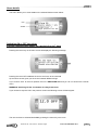
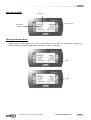
DC50 COMFORT DISPLAY
This display is mounted on the panel of the unit and can be also used as a remote controller; this display is
designed for non-technician user. This display gives information such as flow or pump status, set point and
outside air temperature. It does not allow access to detailed operating data.
It can be used to set or change the scheduling of the different time zones, the temperature set point for each
zone.
It also has the capacity to set a 3 hours override and to force the unoccupied mode or any of the different
time zones for a period of up to 7 days. It displays the real time clock and different faults signals.
Display
Type FSTN graphic
Back light: Green LEDs
Resolution 120x32 pixels
Power Supply
Voltage from main Climatic board
Max power: 0.8W
Remote Installation
The optional DC50 is designed to be mounted on the wall.
• Fit the cable from the DT50 board through the back piece
• Fasten the back piece to the wall using the rounded head screws supplied in the packaging
• Connect the cable from the main board on the RJ12 plug on the back of the DC50 display
• Fasten the front panel on the back piece using the flush head screws supplied
• Finally fit the click-on frame
CLIMATIC 50 user manual – Chillers ranges
CL50-CHILLERS/IOM/1105-E
4343
Terminal connection board installation guide DT 50
The board is fitted with three "telephone" RJ12 plugs. Ensure the board is correctly connected.
Standard connection is:
• Climatic on connector C
• Unit DC50 on connector A
• Remote DC50 on connector SC
• DS50 on connector B
Jumpers:
"Displays" are supplied directly by the Climatic board with 30Vdc. Take particular care at the path this 30V is
taking when several boards are being used.
J14 and J15 can switch on or off the direct current from the power supply:
J14 and J15 set between1-2
Connectors A, B, C and screw connector SC are in parallel. Power supply available to all connectors.
J14 and J15 set between2-3
Connectors B and C are in parallel but line 1 and 6 don't reach connector A and screw connector SC.
"Displays" connected to these ports will not be powered.
If J14 and J15 are set in different positions the "terminal connection board" DT50 DOES NOT WORK.
NOTE:
When a shielded wire is used the metallic case of the "Terminal connection box" DT50 must be earthed.
RJ12 PIN connection
SC Terminals
0
1
2
3
4
5
6
RJ12 Pin conn
+
1
2
3
4
5
6
CLIMATIC 50 user manual – Chillers ranges
Description
shield / earth
+VRL=30V
GND
Rx- / TxRx+ / Tx+
GND
+VRL=30V
CL50-CHILLERS/IOM/1105-E
4444
Terminal display address configuration
The address of the terminal must be checked after having powered the board.
-
To access the configuration mode, press
together and hold them for at least 5 seconds.
-
The screen shown below will be displayed with the cursor flashing in the top left hand corner.
-
To change the address of the terminal display press the
-
Use the
-
If the address was changed it will display the below screen.
key once.
keys to select the desired value and confirm by pressing
.
!
CLIMATIC 50 user manual – Chillers ranges
CL50-CHILLERS/IOM/1105-E
4545
Assigning Terminal displays to control boards.
-
Access the configuration mode by pressing
for at least 5 seconds.
NOTE: To access the board address menu you must go directly to the bottom of the first screen (shown in
below screen) without changing the terminal address as explained above.
-
Press the
-
Use the
-
Pressing
-
Pressing
again will display the screen shown below.
The field "P:XX " shows the address of the selected board. In the example the value "12" has been
selected.
The filed under the "Adr" column represents the addresses of the terminal displays associated with the
board that has the address "12", while the column under "Priv/Shared " indicate the type of terminal
selected.
Ph: Private
Sh :Shared
Sp : Shared Printer (N/A)
To exit the configuration procedure and save the data, select the filed "OK?NO", choose "Yes" using the
keys and confirm by pressing
.
-
-
key until the cursor moves to the field "I/O Board address :XX" (below screen)
key to select the correct Climatic board.(N° of Unit)
again will display the screen shown below :
If the terminal remains inactive (no button is pressed) for 30 seconds, the configuration procedure is
aborted automatically.
CLIMATIC 50 user manual – Chillers ranges
CL50-CHILLERS/IOM/1105-E
4646
Keys
Increase a Value or go to
“Override menu”
Time zone setting
Set time
Change field or validate
Decrease a value or
go to "override menu"
Back to Main Screen or
Cancel “Override”
Main Screen
Water temperature outlet
Flow status
Unit operating mode :
Cooling or heating
Outdoor air temperature
CLIMATIC 50 user manual – Chillers ranges
Current time zone
Z:A
Z:B
Z:C
Uno
Ove
BMS
CL50-CHILLERS/IOM/1105-E
4747
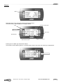
Override 3 hours
From main screen press any of the two arrow keys as shown bellow:
Main screen
Override menu
Increase
Valid/Go next line
Valid/Go main screen
Decrease
It will revert back to main screen after 15 seconds, if no activity
Clock Menu
From main screen press the clock key, the following menu appears:
Increase
Valid
Back to main
CLIMATIC 50 user manual – Chillers ranges
Decrease
CL50-CHILLERS/IOM/1105-E
4848
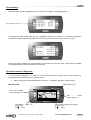
“Time Zone” Menu
From main screen press the “Prg” key, the following menu appears:
Schedule
Increase
Change time zone
Valid go next field
Back to main
Decrease
This page allows you to select the set point for cooling and heating for each time zone.
Calculated set point
Example:
The gradient can be
positive or negative
Outdoor air
temperature
Calculated set point
Example:
The gradient can be
positive or negative
Outdoor air
temperature
It will revert back to main screen after 15 seconds if no activity.
CLIMATIC 50 user manual – Chillers ranges
CL50-CHILLERS/IOM/1105-E
4949
“Scheduling” Menu
The scheduling menu can be accessed from the “time zone” menu by pressing “Prg” again
Increase
Change day
Valid go next field
Decrease
Back to main
Alarm screen
RED
AMBER
Alarm history
Alarm History Menu
RED
AMBER
Alarm history
You can scroll down this menu using the arrow keys and select one of the alarm messages by pressing the
return key.
CLIMATIC 50 user manual – Chillers ranges
CL50-CHILLERS/IOM/1105-E
5050
Alarm details
This menu allows you to view details on the selected fault as shown below:
RED
AMBER
Switching ON or OFF the unit or
Forcing a selected time zones for a period of up to 7 days
Pressing the return key on the main screen will display the following message:
Pressing the return KEY validates the choice and move to the next field
Up and down arrows gives you the choice between different things
If you choose “YES” to the first question the unit is SWITCHED OFF and you can not access the override
menu.
WARNING: Switching Off the unit disable all safety Protections
If you choose to stop the Unit in the previous screen the following screen will then appear.
The unit can then be switched back ON by pressing the return key once more.
CLIMATIC 50 user manual – Chillers ranges
CL50-CHILLERS/IOM/1105-E
5151
If the first choose is “NO” then the override screen can be accessed a particular time zone can be forced for
up to 7 days starting from the day “TODAY”.
In this menu you can choose the number of days you want the selected time zone to override.
Increase the number of days by pressing the Up or down keys.
+ 1 day
Valid
- 1 day
CLIMATIC 50 user manual – Chillers ranges
CL50-CHILLERS/IOM/1105-E
5252
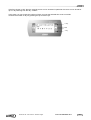
DS50 SERVICE DISPLAY
This display is usually is a plug and play feature designed for technician people.
Keys
Short cut to Alarm menu
Change time zone
Go back to previous screen
Move up in a menu or increase
value
Enter
Valid
Select
Move down in a menu or
decrease a value
Start up screen or Screen (1)
Screen (2) language selection
Start
Ten languages are now available (DE, FR, GB, IT, NL, PL, PT, RO, SP, TR), but only two are downloaded in
the factory. So, the required language must be specified at the time of order.
If needed, other language will be downloaded on site by Lennox technicians.
In this menu the specified language can be selected using the up and down keys. The “prg” key validates the
choice and start the controller
CLIMATIC 50 user manual – Chillers ranges
CL50-CHILLERS/IOM/1105-E
5353
Main menu (0000)
Unit number
Selected item
Capital letter
Current time zone
Moving down the menus
Pressing the arrow keys allows you to move up and down the menu tree. The selected item changes to
CAPITAL letter. It can then be selected by pressing the “return” or “select” key
Down
Select
CLIMATIC 50 user manual – Chillers ranges
CL50-CHILLERS/IOM/1105-E
5454
Sub-menu Data (2000)
Menu Reference
Indicates the menu below
If the menu “GENERAL” is selected, the controller then displays a second level sub-menu.
By selecting the item TEMPERATURE and pressing return, a third level page is displayed as shown bellow:
3x
Pressing “ESC” at any time sends you back one level up the menu tree. In the example shown above “ESC”
must be pressed 3 times to go back to the main menu (0000)
Pressing “ESC” will invalidate any changes made to a value in a setting page.
CLIMATIC 50 user manual – Chillers ranges
CL50-CHILLERS/IOM/1105-E
5555
Alarms
RED
Select the alarm menu using the arrow keys and press return.
The faults history is then displayed in the page (1000):
Number of active Alarm
RED
RESET
Alarm code
Selected Alarm
Alarm Date and Time
Active* or Inactive =
Pressing the “ALARM” key resets all the alarms
The number of active alarms goes to 0, no active alarm shown in the menu, the “bell” key is switched off.
Select
CLIMATIC 50 user manual – Chillers ranges
CL50-CHILLERS/IOM/1105-E
5656
Pressing the “return” key will display details of the selected alarm
Clock settings
The clock setting menu can be accessed from the main menu by selecting the menu “SETTING” and then
navigating down through the sub-menus until page (3120).
Selecting the HOUR for displays the page 3121 shown bellow:
Minimum setting
Validate and back one level
Up one level
Factory setting
Current setting
CLIMATIC 50 user manual – Chillers ranges
Maximum setting
CL50-CHILLERS/IOM/1105-E
5757
Zone Settings
From Main menu (0000) navigate down to sub-menu “SETTINGS”, zone settings (3320).
"Prg" changes the time zone
In this particular page, pressing the “prg” key, changes the time zone. If “SP WAT.1” is selected, this displays
the Minimum Water Outlet Temperature Set Point for the specific time zone shown in the top corner.
Pressing the “prg” validates any changes made, and moves to the next time zone. “ESC” does not validate
the changes and move back one step in the menu tree.
Special screens for diagnostic
For unit operation diagnostic, it is helpful to use the special following screen which can be reached by
pressing the Prg key while being on the screen 2400:
1. Main unit operation (water temperature vs set point , compressor operation, capacity factor)
WA 150 DK HE
Capacity factor (%)
Set point Cooling
and/or Heating (°C)
Compressor status
each circuit
On █
Off [ ]
C: 07.0 █100.0
H:
1:█ █ []
2:█ █ []
for
CLIMATIC 50 user manual – Chillers ranges
14.2
08.5
Inlet
/
Outlet
temperature (°C)
4 way valve or liquid valve status
for each circuit
On █
Off [ ]
CL50-CHILLERS/IOM/1105-E
5858
2. Fans operation (HP vs set point, fan operation, Ventilation factor)
WA 150 DK HE
Ventilation factor circuit 1
and 2 (%)
HP set point circuit
1 and 2 (bars)
HP circuit
and 2 (bars)
1: 16.0 100.0
2: 16.0 075.0
1:█ █
100.0
2:█ █
100.0
Fan status for each circuit
On █
Off [ ]
1
18.0
17.5
PWM factor circuit 1 and
2 (%)
3. Circuit 1 to 4 operation (HP, LP, superheat vs set point)
WA 150 DK HE
Superheat set point (°C), EEV
opening (step), superheat
(°C) – unit with EEV only
Circuit number
C1
Circuit High Pressure
bars and Bubble point
05.0 01478 06.0
H.P. 17.8b 42.8°C
L.P. 04.2b 04.0°C
Suc. 10.0°C
Circuit Low Pressure
bars and Dew point
Suction temperature (°C)
– unit with EEV only
BM 50 address configuration
It may be necessary to change BM50 addresses on the LAN network - mainly in case of Master / Slave
installation. Follow the procedure hereunder to do so:
1. Change the DS50 address to 0
-
Turn the power OFF/ON on the BM50, then access the configuration mode by pressing
seconds until you reach the following screen:
for at least 5
Display address
Setting..........:32
I/O Board address:--
CLIMATIC 50 user manual – Chillers ranges
CL50-CHILLERS/IOM/1105-E
5959
By using
validate with
keys Change the Display addresses setting to 0 (instead of 32 as standard value) and
key.
2. Change the BM50 address
Shut off the power on the BM50 and then turn it on again after 5 seconds, then press alarm and keys in
order to get the following screen
Select
####################
self test
please wait...
####################
Select
Then you will get:
pLan addresse: 0
UP:
increase
DOWN:
decrease
ENTER: save & exit
By using
keys Change the pLan address to the correct value (1 to 4) and validate with
key.
3. Change the DS50 address
Set back the DS 50 address to its normal address (32) with the relevant procedure.
CLIMATIC 50 user manual – Chillers ranges
CL50-CHILLERS/IOM/1105-E
6060
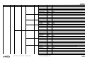
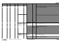
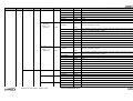
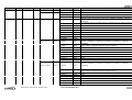
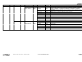
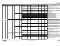
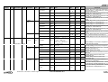
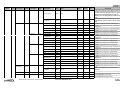
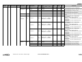
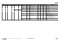
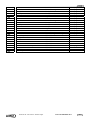
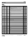
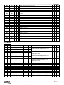
DS50 MENU TREE – ECOLOGIC/ECOMAX RANGE
Main screen
Code
Description
1-Alarm
1000
1-(date).(time)
Code
Description
Code
Description
Code
Unit
2100
1-Temperature
2110
1-Outside
2111
°C
2-Inlet
2112
°C
3-Outlet
2113
°C
4-Wat/Cond
2114
°C
1-SuperHeat
2121
°C
2-T°. Condensing
2122
°C
3-T°- Saturated
2123
°C
4-T°. Suction
2124
°C
5-P. Condensing
2125
b
6-P. Saturated
2126
b
1-SuperHeat
2131
°C
2- T°.Condensing
2132
°C
3- T°- Saturated.
2133
°C
4- T°. Suction.
2134
°C
5- P. Condensing
2135
b
6- P. Saturated
2136
b
1-SuperHeat
2141
°C
2-T°. Condensing
2142
°C
3-T°- Saturated
2143
°C
4-T°. Suction
2144
°C
5-P. Condensing
2145
b
6-P. Saturated
2146
b
1-SuperHeat
2151
°C
2- T°.Condensing
2152
°C
3- T°- Saturated.
2153
°C
4- T°. Suction.
2154
°C
5- P. Condensing
2155
b
6- P. Saturated
2156
b
1-Sw On/Off
2161
On/Off
2-Sw Flow
2162
On/Off
2-(date).(time)
3-(date).(time)
2-Data
2000
1-General
2-Circuit 1
3-Circuit 2
4-Circuit 3
5-Circuit 4
6-Other
CLIMATIC 50 user manual – Chillers ranges
2120
2130
2140
2150
2160
CL50-CHILLERS/IOM/1105-E
6161
Main screen
Code
Description
Code
Description
7-Out. Custom.
8-In. Custom.
9-In. % Custom
2-Control
2200
1-Water
2-Ventilation
3-Pump
CLIMATIC 50 user manual – Chillers ranges
Code
2170
2180
2190
2210
2220
Description
Code
Unit
3-Sw Reset
2163
On/Off
4-Sw Unoc.
2164
On/Off
5-Sw Dis. C1
2165
On/Off
6-Sw Dis. C2
2166
On/Off
7- Sw Dis. C3
2167
On/Off
8- Sw Dis. C4.
2168
On/Off
1-Relay 1
2171
On/Off
2-Relay 2
2172
On/Off
3-Relay 3
2173
On/Off
4-Relay 4
2174
On/Off
1-Switch 1
2181
On/Off
2-Switch 2
2182
On/Off
3-Switch 3
2183
On/Off
4-Switch 4
2184
On/Off
1-Temp. 1
2191
°C
2-Temp. 2
2192
°C
3-Temp. 3
2193
°C
4-Temp. 4
2194
°C
1-Sp Cool
2211
°C
2-Sp Heat
2212
°C
3-Cap.Cool
2213
%
4-Cap.Heat
2214
%
5-Sw 2°Sp
2215
On/Off
6-Offset
2216
°C
1-SetPoint
2221
b
2-Capa. V1
2222
%
3-Capa. V2
2223
%
4-Capa. V3
2224
%
5-Capa. V4
2225
%
1-Config.
2311
Liste: NO / Single / Double
2-State
2312
Liste : Stopped / Started1 / Started2 / Schedule / Fault(1) / Fault(2)
3-Sw Flow
2313
On/Off
4-Sw State
2314
On/Off
5-Relay 1
2315
On/Off
6-Running T. 1
2316
h
7-Relay 2
2317
On/Off
CL50-CHILLERS/IOM/1105-E
6262
Main screen
Code
Description
Code
Description
Code
4-Compressor
2400
1-Comp.1 – C1
2410
2-Comp.2 - C1
2420
Description
Code
8-Running T. 2
2318
h
1-Config.
2411
2-State
2412
3-Sw State
2413
Liste : No / Cool.Only / H.Pump
Liste : Stopped / StartHeat / Started / Start.0.5 / Started1 / Defrost / Wait.Flow / Wait.CH /
Ant-Sho-Cy / Schedule / Switch / Fault(1)
On/Off
4-Sw High P.
2414
On/Off
5-Sw Low P.
2415
On/Off
6-Relay
2416
On/Off
7-H.Pump
2417
On/Off
8-Valve
2418
On/Off
9-Run Time
2419
h
2421
1-Config.
2422
Liste : No / Cool.Only / H.Pump
Liste : Stopped / StartHeat / Started / Start.0.5 / Started1 / Defrost / Wait.Flow / Wait.CH /
Ant-Sho-Cy / Schedule / Switch / Fault(1)
3-Sw State
2423
On/Off
4-Sw High P.
2424
On/Off
5-Sw Low P.
2425
On/Off
6-Relay
7-H.Pump
2426
2427
On/Off
On/Off
8-Valve
2428
On/Off
9-Run Time
2429
h
2-State
3- Comp.3 – C1
(Ecologic)
Comp.1 – C2
(Ecomax)
1-Config.
2430
2432
Liste : Stopped / StartHeat / Started / Start.0.5 / Started1 / Defrost / Wait.Flow / Wait.CH /
Ant-Sho-Cy / Schedule / Switch / Fault(1)
3-Sw State
2433
On/Off
4-Sw High P.
2434
On/Off
5-Sw Low P.
2435
On/Off
6-Relay
7-H.Pump
2436
2437
On/Off
On/Off
8-Valve
2438
On/Off
9-Run Time
2439
h
1-Config.
2440
Liste : No / Cool.Only / H.Pump
2441
2-State
3-Sw State
CLIMATIC 50 user manual – Chillers ranges
Liste : No / Cool.Only / H.Pump
2431
2-State
4- Comp. 1 – C2
(Ecologic)
Comp.2 – C2
(Ecomax)
Unit
2442
Liste : Stopped / StartHeat / Started / Start.0.5 / Started1 / Defrost / Wait.Flow / Wait.CH /
Ant-Sho-Cy / Schedule / Switch / Fault(1)
2443
On/Off
CL50-CHILLERS/IOM/1105-E
6363
Main screen
Code
Description
Code
Description
5- Comp. 2 – C2
(Ecologic)
Comp.1 – C3
(Ecomax)
Code
Description
Code
Unit
4-Sw High P.
2444
On/Off
5-Sw Low P.
2445
On/Off
6-Relay
7-H.Pump
2446
2447
On/Off
On/Off
8-Valve
2448
On/Off
9-Run Time
2449
H
1-Config.
2450
2452
Liste : Stopped / StartHeat / Started / Start.0.5 / Started1 / Defrost / Wait.Flow / Wait.CH /
Ant-Sho-Cy / Schedule / Switch / Fault(1)
3-Sw State
2453
On/Off
4-Sw High P.
2454
On/Off
5-Sw Low P.
2455
On/Off
6-Relay
7-H.Pump
2456
2457
On/Off
On/Off
8-Valve
2458
On/Off
9-Run Time
2459
H
2-State
5- Comp. 3 – C2
(Ecologic)
Comp.1 – C4
(Ecomax)
1-Config.
2460
2500
1-Circuit 1
2-Circuit 2
3-Circuit 3
CLIMATIC 50 user manual – Chillers ranges
2510
2520
2530
Liste : No / Cool.Only / H.Pump
2461
2462
Liste : Stopped / StartHeat / Started / Start.0.5 / Started1 / Defrost / Wait.Flow / Wait.CH /
Ant-Sho-Cy / Schedule / Switch / Fault(1)
3-Sw State
2463
On/Off
4-Sw High P.
2464
On/Off
5-Sw Low P.
2465
On/Off
6-Relay
7-H.Pump
2466
2457
On/Off
On/Off
8-Valve
2458
On/Off
2-State
5-EEV
Liste : No / Cool.Only / H.Pump
2451
9-Run Time
2459
H
1-Config.
2511
Liste : No / Yes
2-State
2512
Liste : Stopped / Started / Wait.Flow / Wait.CH / Schedule / Switch / Fault(1)
3-Position
2513
~
1-Config.
2521
Liste : No / Yes
2-State
2522
Liste : Stopped / Started / Wait.Flow / Wait.CH / Schedule / Switch / Fault(1)
3-Position
2523
~
1-Config.
2531
Liste : No / Yes
2-State
2532
Liste : Stopped / Started / Wait.Flow / Wait.CH / Schedule / Switch / Fault(1)
CL50-CHILLERS/IOM/1105-E
6464
Main screen
Code
Description
Code
Description
4-Circuit 4
6-Ventilation
2600
1-Fan - Circuit 1
1-Fan - Circuit 2
2-Fan 2 - Circuit 3
CLIMATIC 50 user manual – Chillers ranges
Code
2540
2610
2620
2630
Description
Code
Unit
3-Position
2533
~
1-Config.
2541
Liste : No / Yes
2-State
2542
Liste : Stopped / Started / Wait.Flow / Wait.CH / Schedule / Switch / Fault(1)
3-Position
2543
1-Config.
2611
2-State
2612
3-Sw State
2613
~
Liste : No / 1.Yes / 2.Yes / 3.Yes / 4.Yes / 5.Yes / 1.Modulat. / 2.Modulat. / 3.Modulat. /
4.Modulat. / 5.Modulat. / 1.LowSpeed / 2.LowSpeed / 3.LowSpeed / 4.LowSpeed /
5.LowSpeed
Liste : Stopped / Start.0.5 / Started1 / Start.1.5 / Started2 / Start.2.5 / Started3 / Start.3.5 /
Started4 / Start.4.5 / Started5 / Wait.Flow / Wait.CH / Fault(1)
On/Off
4-Relay 1
2614
On/Off
5-Relay 2.
2615
On/Off
6-Relay 3
2616
On/Off
7-Relay 4
2617
On/Off
8-Relay 5
2618
On/Off
9-Modulat.
2619
1-Config.
2621
2-State
2622
3-Sw State
2623
%
Liste : No / 1.Yes / 2.Yes / 3.Yes / 4.Yes / 5.Yes / 1.Modulat. / 2.Modulat. / 3.Modulat. /
4.Modulat. / 5.Modulat. / 1.LowSpeed / 2.LowSpeed / 3.LowSpeed / 4.LowSpeed /
5.LowSpeed
Liste : Stopped / Start.0.5 / Started1 / Start.1.5 / Started2 / Start.2.5 / Started3 / Start.3.5 /
Started4 / Start.4.5 / Started5 / Wait.Flow / Wait.CH / Fault(1)
On/Off
4-Relay 1
2624
On/Off
5-Relay 2.
2625
On/Off
6-Relay 3
2626
On/Off
7-Relay 4
2627
On/Off
8-Relay 5
2628
On/Off
9-Modulat.
2629
1-Config.
2631
%
Liste : No / 1.Yes / 2.Yes / 3.Yes / 4.Yes / 5.Yes / 1.Modulat. / 2.Modulat. / 3.Modulat. /
4.Modulat. / 5.Modulat. / 1.LowSpeed / 2.LowSpeed / 3.LowSpeed / 4.LowSpeed /
5.LowSpeed
2-State
2632
3-Sw State
2633
Liste : Stopped / Start.0.5 / Started1 / Start.1.5 / Started2 / Start.2.5 / Started3 / Start.3.5 /
Started4 / Start.4.5 / Started5 / Wait.Flow / Wait.CH / Fault(1)
On/Off
4-Relay 1
2634
On/Off
5-Relay 2.
2635
On/Off
6-Relay 3
2636
On/Off
7-Relay 4
2637
On/Off
8-Relay 5
2638
On/Off
CL50-CHILLERS/IOM/1105-E
6565
Main screen
Code
Description
Code
Description
1-Fan - Circuit 4
7-Option
2700
1-Free Cooling
2-Heat Recovery
CLIMATIC 50 user manual – Chillers ranges
Code
2640
2710
2720
Description
Code
Unit
9-Modulat.
2639
1-Config.
2641
2-State
2642
3-Sw State
2643
%
Liste : No / 1.Yes / 2.Yes / 3.Yes / 4.Yes / 5.Yes / 1.Modulat. / 2.Modulat. / 3.Modulat. /
4.Modulat. / 5.Modulat. / 1.LowSpeed / 2.LowSpeed / 3.LowSpeed / 4.LowSpeed /
5.LowSpeed
Liste : Stopped / Start.0.5 / Started1 / Start.1.5 / Started2 / Start.2.5 / Started3 / Start.3.5 /
Started4 / Start.4.5 / Started5 / Wait.Flow / Wait.CH / Fault(1)
On/Off
4-Relay 1
2644
On/Off
5-Relay 2.
2645
On/Off
6-Relay 3
2646
On/Off
7-Relay 4
2647
On/Off
8-Relay 5
2648
On/Off
9-Modulat.
2649
%
1- Config.
2711
Liste : No / Yes
2- State
2712
Liste : Stopped / Started / Wait.Flow / Wait.CH
1-Config.
2721
Liste : No / Yes
2- State
2722
Liste : Stopped / Started / Wait.Flow / Wait.CH
3- Inlet
2723
°C
4- Outlet
2724
°C
5-Sw State
2725
On/Off
CL50-CHILLERS/IOM/1105-E
6666
Main
screen
Code
Description
Code
3-Setting
3000
1-General
3100
Description
1-Order
2-Clock
1-Time
2-Schedule
3120
3210
Description
1-On/Off
Code
3111
2-Pompe
3112
Unit
On/Off
Liste : Started / Stopped /
P1 Only / P2 Only / P1-N
P2-R / P2-N P1-R / Clock
3-Reset Al.
3113
Yes/No
4-Resume
3114
Yes/No
1-Change
over
3220
3310
Factory
Max
~
Off
~
*[On / Off] Unit
0
0
6
pump operation mode set up (see Pump
operation description page 12 – IOM Climatic 50)
~
Off
~
~
Off
~
0
0
3
Lennox set point
0
~
23
*[Clock] Clock setting "Hour"
*[Clock] Clock setting "minute’’
*[Clock] Clock setting "Day"
*[Clock] Clock setting "Month"
*[Clock] Clock setting "Year"
*[Clock] automatic switch summer time /
winter time
*[Zone Setting] Starting time "Hour" for
"Unocupied" zone – set 6.3 to get 6h30mn –
modulo 10mn
*[Zone Setting] Starting time for "Zone A" –
set 6.3 to get 6h30mn – modulo 10mn
*[Zone Setting] Starting time for "Zone B" –
set 6.3 to get 6h30mn – modulo 10mn
*[Zone Setting] Starting time for "Zone C" –
set 6.3 to get 6h30mn – modulo 10mn
*[Anticipation Function] Bottom of the slope
in °C. Limit of activation of the function. This
allows an anticipated startup in the morning
depending on the outdoor temperature.
Only for the "Zone-A"
*[Anticipation Function] Slope in "Minutes of
anticipation per degrees".
*[Change over] Change over mode for heat
3115
1-Hour
3121
2-Minute
3122
m
0
~
59
3-Day
3123
~
1
~
31
4-Month
3124
~
1
~
12
5-Year
3125
~
2
~
99
6-Win/Sum
3126
Yes/No
~
Yes
~
1-Start Uno
3211
h
0
24
24
0
0
24
0
24
24
0
24
24
-10
10
20
0
0
100
2-Start z.A
3212
h
3-Start z.B
3213
h
4-Start z.C
3214
h
1-Foot
3221
°C
2-Gradient
3222
mn/°C
1-Mode
3311
Liste : Cool. Only / Heat.
Only / Auto. / Auto.Stop.
0
0
2-Winter
3312
°C
-10
19
50
3-Summer
3313
°C
-10
22
50
1-Sp Wat.1
3321
°C
3
CL50-CHILLERS/IOM/1105-E
pump units, 0: chiller only, 1: HP only, 2:
automatic with pump, 3:automatic without pump
operation.
*[Change over] Change over winter setting
*[Change over] Change over summer setting
*[Water SP] Outlet chilled water temperature set
point (see page 14 – IOM Climatic 50) – minimum
with Glycol according to %
5 / -10
CLIMATIC 50 user manual – Chillers ranges
Comments
*[Reset] Discharges the safety measures of
the unit
*[Override] Cancel any override action set
with the DC50
5-Test
3300
2 -Water
Cool
Min
Liste : . / Quickly / Defrost
/ 24/24 7/7
H
3200
2Anticipation
3-Control
Code
3110
7
17
6767
Main
screen
Code
Description
Code
Description
Code
Description
2-Sp Wat.2
3-Water
Heat
4-Safety
1-Circuit
4Compressor
3330
3340
3410
Code
3322
3-Defrost
3420
3430
CLIMATIC 50 user manual – Chillers ranges
Min
Factory
Max
3323
°C
4-Sp Out.2
3324
°C
5-Reactiv.
3325
%/°C
1-Sp Wat.1
3331
°C
2-Sp Wat.2
3332
°C
3-Sp Out.1
3333
°C
4-Sp Out.2
3334
°C
5-Reactiv.
3335
%/°C
1-Wat. Low
3341
°C
2-Wat. high
3342
1-Enable
3411
°C
Liste : C1_ _ _ / C _2_ _ /
C12_ _ / C _ _3_ / C1_3_
/ C _23_ / C123_ / C _ _
_4 / C1_ _ 4 / C_2_4 /
C12 _4 / C _ _34 / C1_34
/ C_234 / C1234
Liste : Auto. / C.1 / C.2 /
C.3 / C.4
2-Rotat.
3412
1-Frost
3421
°C
2-Time limit
3422
s
3- T.Disch
3423
°C
4- W/Cd Mini
3424
°C
5- W/Cd Maxi
3425
°C
1-Mode
3431
Liste : Dynamic / Cyclic
2-Outside
3432
°C
3-Coil
3433
°C
CL50-CHILLERS/IOM/1105-E
Comments
*[Water SP] Outlet chilled water temperature set
°C
3-Sp Out.1
3400
2-Safety
Unit
5 / -10
7
17
-10
22
50
-10
30
50
1
5
50
17
40
50
17
40
50
-10
19
50
-10
0
50
1
5
50
3 / -10
5 / -10
12
point (see page 11 – IOM Climatic 50) – minimum
with Glycol according to %
*[Water SP] Ambiant air temperature set point
(see page 13 – IOM Climatic 50)
*[Water SP] Ambiant air temperature set point
(see page 13 – IOM Climatic 50)
*[Capacity Factor] Reactivity factor for cooling
mode
*[Water SP] Outlet hot water temperature set
point (see page 13 – IOM Climatic 50)
*[Water SP] Outlet hot water temperature set
point (see page 13 – IOM Climatic 50)
*[Water SP] Ambiant air temperature set point
(see page 13 – IOM Climatic 50)
*[Water SP] Ambiant air temperature set point
(see page 13 – IOM Climatic 50)
*[Capacity Factor] Reactivity factor for heating
mode
*[Safety limit] Chilled water outlet temperature
limit – minimum with Glycol according to %
22
53
53
*[Safety limit] Hot water outlet temperature limit
1
3 / 15
3 / 15
Circuit authorize to operate
0
0
4
*[Comp priority] Circuit priority management
*[Safety limit] Freezing safety limit – minimum
-1/-20
-1 / -20
5
with Glycol according to %
1
30
360
*[Safety limit] Lennox setting
*[Temp. SP] Discharge temperature set point
90
110
120
WAH only
5
25
33
20
55
66
0
0
2
8
10
20
1/-10
2
3 / 10
*[Circ enable] Circuit operation management –
*[Safety limit] Condensing water outlet
temperature limit
*[Safety limit] Condensing water outlet
temperature limit
*[ Function Defrost ] Choice of defrost: 1 =
"cycling" or 0 ="dynamic"
*[ Function Defrost ] Authorization of defrost
- Threshold of outside temperature (in °c)
*[ Function Defrost ] Authorization of defrost
- Threshold of coil temperature (in °c)
6868
Main
screen
Code
Description
Code
Description
Code
Description
4-Time Limit
5-EEV
3500
1-Circuit 1
2-Circuit 2
3-Circuit 3
4-Circuit 4
6Ventilation
3510
3520
3530
3540
3600
Code
3434
Unit
Min
3700
8-Config.
3800
1-Unit
3810
CLIMATIC 50 user manual – Chillers ranges
Max
Comments
*[ Function Defrost ] Time limit for icing (in
minute) -For the dynamic defrost the unit will
run this minimum amount of time. If cycling
defrost this is the time delay to start the
defrost once the temperature conditions are
met.
*[ Function Defrost ] Running time of fans
after defrost cycle in order to dry the outside
coil.
*[ EEV] Superheat set point – With Glycol
*[ EEV] Lennox set point – EEV opening at 1st
mn
1
30
360
5
60
300
5/7
5/7
15
5-Time Fc
3435
s
1-SuperHeat
3511
°C
2-Anticipation
3512
%
0
80
100
stage start
3-P
3513
°C
5
Calc
30
4-I
3514
s
10
35
100
5-D
3515
s
0,5
1
3
1-SuperHeat
3521
°C
5/7
5/7
15
2-Anticipation
3522
%
*[ EEV] Lennox set point – Proportional factor
*[ EEV] Lennox set point – Integral factor
*[ EEV] Lennox set point – Derivate factor
*[ EEV] Superheat set point – With Glycol
*[ EEV] Lennox set point – EEV opening at 1st
0
80
100
stage start
3-P
3523
°C
5
Calc
30
4-I
3524
s
10
35
100
5-D
3525
s
0,5
1
3
1-SuperHeat
3531
°C
5/7
5/7
15
2-Anticipation
3532
%
*[ EEV] Lennox set point – Proportional factor
*[ EEV] Lennox set point – Integral factor
*[ EEV] Lennox set point – Derivate factor
*[ EEV] Superheat set point – With Glycol
*[ EEV] Lennox set point – EEV opening at 1st
0
80
100
stage start
3-P
3533
°C
5
Calc
30
4-I
3534
s
10
35
100
5-D
3535
s
0,5
1
3
1-SuperHeat
3541
°C
5/7
5/7
15
2-Anticipation
3542
%
*[ EEV] Lennox set point – Proportional factor
*[ EEV] Lennox set point – Integral factor
*[ EEV] Lennox set point – Derivate factor
*[ EEV] Superheat set point – With Glycol
*[ EEV] Lennox set point – EEV opening at 1st
0
80
100
stage start
3-P
3543
°C
5
Calc
30
4-I
3544
s
10
35
100
5-D
3545
s
0,5
1
3
1-Sp Cond.
3611
b
*[ EEV] Lennox set point – Proportional factor
*[ EEV] Lennox set point – Integral factor
*[ EEV] Lennox set point – Derivate factor
*[ HP SP] High pressure set point – for R134a
11
16 / 11
21
2-Reactiv.
3612
%/°C
operation
10
50
1-Range
3811
Liste
0
~
8/6
2-Size
3812
Liste
0
~
83/126
CL50-CHILLERS/IOM/1105-E
unit
*[ HP Factor] Reactivity set point for fan
1
7-Option
Factory
*[ Configuration ] Unit model
*[ Configuration ] Type of unit
6969
Main
screen
Code
Description
Code
Description
2Compressor
Code
3820
Description
Code
Unit
Liste : R407c / R22 /
R134a
3- gaz
3813
1-EEV
3821
Yes/No
2-LAK
3822
Yes/No
3-Stages +.
3823
Yes/No
4-Starter
3824
Yes/No
Min
Factory
Max
0
~
2
*[ Configuration ] Type of refrigerant
*[ Configuration ] Electronic expansion valve
*[ Configuration ] All season control
*[ Configuration ] For units with reciprocating
~
~
~
~
~
~
~
~
~
~
~
~
Comments
compressor extra capacity reduction
*[ Configuration ] For units with compressor soft
starter
*[ Configuration ] Fan configuration
3Ventilation
3830
1-Circuit 1
3831
Liste : No / Stages /
Modulation / Low Speed
0
0
3
No = No fans
Stages + = Single speed stage fans
Modulation = 1 fan with speed control, others with
single speed
Low Speed = 1 fan with 2 speed others with
single speed
*[ Configuration ] Fan configuration
2-Circuit 2
3832
Liste : No / Stages /
Modulation / Low Speed
0
0
3
No = No fans
Stages + = Single speed stage fans
Modulation = 1 fan with speed control, others with
single speed
Low Speed = 1 fan with 2 speed others with
single speed
*[ Configuration ] Fan configuration
3-Circuit 3
3833
Liste : No / Stages /
Modulation / Low Speed
0
0
3
No = No fans
Stages + = Single speed stage fans
Modulation = 1 fan with speed control, others with
single speed
Low Speed = 1 fan with 2 speed others with
single speed
*[ Configuration ] Fan configuration
4-Circuit 4
4-Option.
3840
CLIMATIC 50 user manual – Chillers ranges
3834
Liste : No / Stages /
Modulation / Low Speed
1-Pump
3841
2-Glycol
3842
Liste : No
Double
%
3-Recovery
3843
Yes/No
/
Simple
CL50-CHILLERS/IOM/1105-E
0
0
3
/
0
~
2
0
~
50
~
~
~
No = No fans
Stages + = Single speed stage fans
Modulation = 1 fan with speed control, others with
single speed
Low Speed = 1 fan with 2 speed others with
single speed
*[ Configuration ] Pump configuration
*[ Configuration ] Glycol persentage
*[ Configuration ] Heat recovery option
7070
Main
screen
Code
Description
Code
Description
5-Out.
Custom.
6-In. Custom.
7-In.%
Custom.
Code
3850
3860
3870
Description
Code
1-BE50.1
3851
2-BE50.2
3852
3-BE50.3
3853
4-BE50.4
3854
1-BE50.1
3861
2-BE50.2
3862
3-BE50.3
3863
4-BE50.4
3864
1-BE50.1
3871
2-BE50.2
Unit
Liste : Not Used / C.1
Alarm / C.2 Alarm / C.3
Alarm : C.4 Alarm / Fans
Al. / Pump Al. / Flow Al./
Heat. Mode / C.1 100% /
C.2 100% / C.3 100% /
C.4 100% / U. 100% / U.
On / Z:A / Z:B / Z:C / Uno /
Bms / Free
Liste : Not Used / Sw
Setpoint / Sw Cool. / Sw
Heat. / C1 Disable / C2
Disable / C3 Disable / C4
Disable / Sw Unoc. / Free
4-BE50.4
1-Display
9-Com.
3910
1-Standard Sp
3920
1-ID
2-Number
CLIMATIC 50 user manual – Chillers ranges
Max
0
0
20
0
0
20
0
0
20
0
0
20
0
0
9
0
0
9
0
0
9
0
0
9
0
0
2
0
0
2
0
0
2
0
0
2
~
Off
~
1
~
4/2
1
1
4/2
3873
3874
3911
Yes/No
3900
2Master/Slave
Factory
3872
Liste : Not Used / S.P Offset
/ Free NTC
3-BE50.3
Min
3921
3922
~
~
CL50-CHILLERS/IOM/1105-E
Comments
*[Configuration] Free output to be customised
(First output of the extension board BE50)
*[Configuration] Free output to be customised
(Second output of the extension board BE50)
*[Configuration] Free output to be customised
(Third output of the extension board BE50)
*[Configuration] Free output to be customised
(Fourth output of the extension board BE50)
*[Configuration] Free input to be customised
(input of the extension board BE50)
*[Configuration] Free input to be customised
(input of the extension board BE50)
*[Configuration] Free input to be customised
(input of the extension board BE50)
*[Configuration] Free input to be customised
(input of the extension board BE50)
*[Configuration] Free input to be
customised (input of the extension board
BE50)
*[Configuration] Free input to be
customised (input of the extension board
BE50)
*[Configuration] Free input to be
customised (input of the extension board
BE50)
*[Configuration] Free input to be
customised (input of the extension board
BE50)
*Allows a reset of ALL set point to
standard factory settings (when
available).No possible for configurations.
and clock as there is no factory settings
for these.
*[ Configuration ] Identification address
for the unit from 1 to 4 for master slave
operation.
*[ Configuration ] Number of units on the
BUS. Unit with address N°1 is always the
master.
7171
Main
screen
Code
Description
Code
Description
Code
Description
3-Type
3930
3924
/
M/S
5-Outside
3925
Liste : Not Used
Temp. / M/S Aver.
/
M/S
1-ID
3931
~
2-Type
3932
Liste : Climatic / ModBus /
LonWorks/ Web
3933
Liste : 1200 / 2400 / 4800 /
9600 / 19200
3-Baud
4-Watchdog
5-BMS Unoc.
CLIMATIC 50 user manual – Chillers ranges
3923
Unit
Liste : Not Used / Backup /
Rol.Backup / Cascade
Liste : Not Used
Temp. / M/S Aver.
4-Outlet
3-BMS
Code
3934
3935
Min
Factory
Max
0
0
2
0
0
2
0
0
2
1
1
200
0
0
2
0
3
4
~
On/Off
CL50-CHILLERS/IOM/1105-E
0
0
1000
~
Off
~
Comments
*Master / Slave relationship: refer to page
7 for details
*Master / Slave relationship: refer to page
7 for details
*Master / Slave relationship: refer to page
7 for details
*[ Configuration ] Identification number on
the 485 Bus
*[ Configuration ] Type of BMS 0 Mode
Lennox Climatic; 1 MODBUS; 2
LONWORKS
BMS communication speed between
1200BDS and 19800
*[ BMS ] Activation of the control by a
computer or an automat
- mode BMS is activated if this value is
different from zero, This value is
decreased every second
*[BMS] Cancel the override unoccupied
mode
7272
FAULTS CODES
1
4
5
11
12
13
14
15
22
23
31
32
33
40
41
42
70
71
72
73
74
75
76
80
81
82
83
84
85
86
87
88
90
91
92
93
94
95
96
97
98
99
111
112
114
115
117
118
121
122
124
125
Water Flow
Filters
Filters
Electrical Heater
Outlet water T° or Supply air T°
Intlet water T° or Room air T°
Gas Burner, 1
Gas Burner, 2
Outlet water T° or Supply air T°
Intlet water T° or Room air T°
Humidifier
Room Humidity
Room Humidity
Flow, Pump
Pump, 1
Pump, 2
Real Time Clock
BE50, 1
BE50, 2
BE50, 3
BE50, 4
BE50, 5
BM50, Slave
Remote S.Point
Intlet water T° or Room air T°
Room Humidity
Outside air Temperature
Outside Humidity
Outlet or Supply T.
Inlet, Heat Recovery
Outlet, Heat Recovery
Return or Mixing T.
Air, Condenser fan
Blower, Fan
Air, Condenser fan
Air, Condenser fan
Air, Condenser fan
Air, Condenser fan
Water, Condenser
Water, Condenser
Water, Condenser
Fire / Smoke
High Pressure
Low presure
Circuit 1
Circuit 1
Circuit 1
Circuit 1
High Pressure
Low presure
Circuit 2
Circuit 2
CLIMATIC 50 user manual – Chillers ranges
Flow switch cut off
Dirty
Missing
Faulty
Too high T°
Too Low T°
Faulty
Faulty
Too Low T°
Too high T°
Faulty
Humidity Too Low
Humidity Too High
Failure
Electric failure
Electric failure
Faulty
Faulty communication
Faulty
Faulty
Faulty
Faulty
Faulty
Faulty
Faulty Sensor
Faulty Sensor
Faulty Sensor
Faulty Sensor
Faulty Sensor
Faulty Sensor
Faulty Sensor
Faulty Sensor
Faulty
Faulty
Faulty, System 1
Faulty, System 2
Faulty, System 3
Faulty, System 4
Temp. Too low
Temp. Too High
Faulty, Flow
Faulty
Faulty Sensor, 1
Faulty Sensor, 1
Compressor elec. failure
High Pressure cut
Low Pressure cut
Risk of Frosting
Faulty Sensor, 2
Faulty Sensor, 2
Compressor elec. failure
High Pressure cut
See page 29 & 36
See page 28
See page 28
See page 28
See page 28
See page 36
See page 38
See page 38
See page 30
See page 33
See page 33
See page 33
See page 33
See page 37
See page 37
See page 37
See page 37
See page 37
See page 33
See page 34
See page 35
See page 31
See page 32
See page 33
See page 34
See page 35
CL50-CHILLERS/IOM/1105-E
7373
127
128
131
132
134
135
137
138
141
142
144
145
147
148
2n0
2n1
2n2
2n3
2n4
2n5
2n6
2n7
2n8
2n9
Circuit 2
Circuit 2
High Pressure
Low presure
Circuit 3
Circuit 3
Circuit 3
Circuit 3
High Pressure
Low presure
Circuit 4
Circuit 4
Circuit 4
Circuit 4
Circuit n
Low Superheat
High Suction T.
MOP
LOP
Valve Not Closed
LP sensor or suction probe
Motor
EEPROM
Battery
CLIMATIC 50 user manual – Chillers ranges
Low Pressure Cut
Risk of Frosting
Faulty Sensor, 3
Faulty Sensor, 3
Compressor elec. failure
High Pressure cut
Low Pressure Cut
Risk of Frosting
Faulty Sensor, 4
Faulty Sensor, 4
Compressor elec. failure
High Pressure cut
Low Pressure Cut
Risk of Frosting
EEV n, Wrong addressing
EEV n, Error
EEV n, Error
EEV n, Error
EEV n, Error
EEV n, Error
EEV n, Error
EEV n, Error
EEV n, Error
EEV n, Error
See page 31
See page 32
See page 33
See page 33
See page 34
See page 35
See page 31
See page 32
See page 33
See page 33
See page 34
See page 35
See page 31
See page 32
See page 21
See page 33
CL50-CHILLERS/IOM/1105-E
7474
BMS Points
ModBus
Analogical
@ (hexa) @ (deci)
[ BMS ] Activation of the control by a computer or an automat - mode BMS is
activated if this value is different from zero, This value is decreased every
second
[Unit] without pump: 0=Started; 1=Stopped
[Unit] with pump: 1=Stopped; 2:P1 Only; 3=P2 Only; 4=P1-N P2-S; 5=P2-N P1S; 6=P1/P2 by clock
WA
LC
DS50
√
√
3934
√
√
3112
BMS
01H
1
R/W
1=1s
02H
2
R/W
1=1
03H
3
R/W
1=1
[Unit] Change-over: 0=Cool. Only; 1=Heat. Only; 2=Auto. Pump; 3=Auto. No
Pump
√
04H
4
R/W
1=1
[Unit] Activation of the circuits: bit.0=C1; bit.1=C2; bit.2=C3; bit.3=C4
√
√
3411
BMS
05H
5
R/W 10 = 1.0°c
[Occupation][Water SP] Required maximum water temperature in °C. Cooling
set point
√
√
3321
BMS
06H
6
R/W 10 = 1.0°c
[Occupation][Water SP] Required minimum water temperature in °C. Heating set
point
√
07H
7
R/W 10 = 1.0°c
[Inoccupation][Water SP] Required maximum water temperature in °C. Cooling
set point
√
08H
8
R/W 10 = 1.0°c
[Inoccupation][Water SP] Required minimum water temperature in °C. Heating
set point
√
09H
9
R/W
not used
0AH
10
R/W
not used
0BH
11
R/W
not used
0CH
12
R/W
1 = 1h
[Clock] Hour
√
√
3121
0DH
13
R/W
1 = 1m
[Clock] Minute
√
√
3122
0EH
14
R/W
1=1
[Clock] Day of the month
√
√
3123
0FH
15
R/W
1=1
[Clock] Month
√
√
3124
10H
16
R/W
1 = 2001
[Clock] Year
√
√
3125
11H
17
R/W
not used
12H
18
R/W
not used
13H
19
R/W 10 = 1.0°c
[BMS] Outdoor temperature coming from the BMS
√
√
…
14H
20
R/W
not used
15H
21
R/W
not used
16H
22
R/W
not used
17H
23
R/W
not used
18H
24
R/W
not used
19H
25
R/W
not used
1AH
26
R/W
not used
1BH
27
R/W
not used
1CH
28
R/W
not used
1DH
29
R/W
not used
1EH
30
R/W
not used
1FH
31
R/W
not used
20H
32
R/W
not used
CLIMATIC 50 user manual – Chillers ranges
CL50-CHILLERS/IOM/1105-E
3311
BMS
3331
BMS
√
3321
Uno
3331
Uno
7575
21H
33
R
1=1
22H
34
R
23H
35
24H
[Alarm] Code Error
√
√
1000
10 = 1.0°c
[Temperature] Intlet, Water
√
√
2112
R
10 = 1.0°c
[Temperature] Outdoor, Air
√
√
2111
36
R
10 = 1.0°c
[Temperature] Outlet, Water
√
√
2113
25H
37
R
10 = 1.0b
[Pressure] High, Circuit 1
√
√
2125
26H
38
R
10 = 1.0b
[Pressure] Low, Circuit 1
√
√
2126
27H
39
R
10 = 1.0b
[Pressure] High, Circuit 2
√
√
2135
28H
40
R
10 = 1.0b
[Pressure] Low, Circuit 2
√
√
2136
29H
41
R
10 = 1.0b
[Pressure] High, Circuit 3
√
2145
2AH
42
R
10 = 1.0b
[Pressure] Low, Circuit 3
√
2146
2BH
43
R
10 = 1.0b
[Pressure] High, Circuit 4
√
2155
2CH
44
R
10 = 1.0b
[Pressure] Low, Circuit 4
√
2156
2DH
45
R
1 = 1%
[% of opening] Fan, Modulation, Circuit 1
√
√
2619
2EH
46
R
1 = 1%
[% of opening] Fan, Modulation, Circuit 2
√
√
2629
2FH
47
R
1 = 1%
[% of opening] Fan, Modulation, Circuit 3
√
2639
30H
48
R
1 = 1%
[% of opening] Fan, Modulation, Circuit 4
√
2649
31H
49
R
10 = 1.0°c
[Dry contact] Temperature, Free 1, BE50-J9-B1
√
√
2191
32H
50
R
10 = 1.0°c
[Dry contact] Temperature, Free 2, BE50-J9-B2
√
√
2192
33H
51
R
10 = 1.0°c
[Dry contact] Temperature, Free 3, BE50-J10-B3
√
√
2193
34H
52
R
10 = 1.0°c
[Dry contact] Temperature, Free 4, BE50-J10-B4
√
√
2194
35H
53
R
1=1
[Fan] Numbers which run, Circuit 1
√
√
…
36H
54
R
1=1
[Fan] Numbers which run, Circuit 2
√
√
…
37H
55
R
1=1
[Fan] Numbers which run, Circuit 3
√
…
38H
56
R
1=1
[Fan] Numbers which run, Circuit 4
√
…
39H
57
R
10 = 1.0°c
[EEV] Current superheating value, Circuit 1
√
√
2121
3AH
58
R
10 = 1.0°c
[EEV] Current superheating value, Circuit 2
√
√
2131
3BH
59
R
10 = 1.0°c
[EEV] Current superheating value, Circuit 3
√
2141
3CH
60
R
10 = 1.0°c
[EEV] Current superheating value, Circuit 4
√
2151
3DH
61
R
10 = 1.0°c
[EEV] Saturated evaporation temperature, Circuit 1
√
√
2124
3EH
62
R
10 = 1.0°c
[EEV] Saturated evaporation temperature, Circuit 2
√
√
2134
3FH
63
R
10 = 1.0°c
[EEV] Saturated evaporation temperature, Circuit 3
√
2144
40H
64
R
10 = 1.0°c
[EEV] Saturated evaporation temperature, Circuit 4
√
2154
CLIMATIC 50 user manual – Chillers ranges
CL50-CHILLERS/IOM/1105-E
7676
Logical
@ (hexa) @ (deci)
WA LC DS50
01H
1
R/W L
[On/Off] Unit
√
√
3111
02H
2
R/W L
[Reset] Discharges the safety measures of the unit
√
√
3113
03H
3
R/W L
not used
04H
4
R/W L
not used
05H
5
R/W L
[BMS] Activation of the Inoccupation mode [Off] occupation mode - [On] inoccupation
mode
√
√
3935
06H
6
R/W L
not used
07H
7
R/W L
not used
08H
8
R/W L
not used
09H
9
R/W L
not used
0AH
10
R/W L
not used
0BH
11
R/W L
not used
0CH
12
R/W L
not used
0DH
13
R/W L
not used
0EH
14
R/W L
not used
0FH
15
R/W L
not used
10H
16
R/W L
[Clock] [OFF] read hour & minute [ON] write hour & minute
√
√
…
11H
17
R/W L
not used
12H
18
R/W L
[Dry contact] Digital Output, Free 2, BE50-J5-NO1
√
√
2171
13H
19
R/W L
[Dry contact] Digital Output, Free 3, BE50-J6-NO2
√
√
2172
14H
20
R/W L
[Dry contact] Digital Output, Free 4, BE50-J7-NO3
√
√
2173
15H
21
R/W L
[Dry contact] Digital Output, Free 5, BE50-J8-NO4
√
√
2174
16H
22
R/W L
not used
17H
23
R/W L
not used
18H
24
R/W L
not used
19H
25
R/W L
not used
1AH
26
R/W L
not used
1BH
27
R/W L
not used
1CH
28
R/W L
not used
1DH
29
R/W L
not used
1EH
30
R/W L
not used
1FH
31
R/W L
not used
20H
32
R/W L
not used
21H
33
R
L
[Alarm] General
√
√
1000
22H
34
R
L
[On/Off] Pump, 1
√
√
2315
23H
35
R
L
[On/Off] Pump, 2
√
√
2317
24H
36
R
L
[On/Off] Compressor 1, Circuit 1
√
√
2416
25H
37
R
L
[On/Off] Compressor 2, Circuit 1
√
√
2426
26H
38
R
L
[On/Off] Compressor 3, Circuit 1 (WA) or Compressor 1, Circuit 3 (LC)
√
√
2436
27H
39
R
L
[On/Off] Compressor, Heat pump, Circuit 1
√
28H
40
R
L
[On/Off] Compressor 1, Circuit 2
√
√
2446
29H
41
R
L
[On/Off] Compressor 2, Circuit 2
√
√
2456
2AH
42
R
L
[On/Off] Compressor 3, Circuit 2 (WA) or Compressor 1, Circuit 4 (LC)
√
√
2466
CLIMATIC 50 user manual – Chillers ranges
CL50-CHILLERS/IOM/1105-E
2417
7777
2BH
43
R
L
[On/Off] Compressor, Heat pump, Circuit 2
2CH
44
R
L
not used
2DH
45
R
L
not used
2EH
46
R
L
not used
2FH
47
R
L
not used
30H
48
R
L
not used
31H
49
R
L
not used
32H
50
R
L
not used
33H
51
R
L
[Dry contact] Digital Input, Free 3, BE50-J4-ID1
√
√
2181
34H
52
R
L
[Dry contact] Digital Input, Free 4, BE50-J4-ID2
√
√
2182
35H
53
R
L
[Dry contact] Digital Input, Free 5, BE50-J4-ID3
√
√
2183
36H
54
R
L
[Dry contact] Digital Input, Free 6, BE50-J4-ID4
√
√
2184
37H
55
R
L
[On/Off] Fan 1, High speed, Circuit 1
√
√
2614
38H
56
R
L
[On/Off] Fan 2, Circuit 1
√
√
2615
39H
57
R
L
[On/Off] Fan 3, Circuit 1
√
√
2616
3AH
58
R
L
[On/Off] Fan 4, Circuit 1
√
√
2617
3BH
59
R
L
[On/Off] Fan 5, Circuit 1
√
2618
3CH
60
R
L
[On/Off] Fan 1, High speed, Circuit 2
√
√
2624
3DH
61
R
L
[On/Off] Fan 2, Circuit 2
√
√
2625
3EH
62
R
L
[On/Off] Fan 3, Circuit 2
√
√
2626
3FH
63
R
L
[On/Off] Fan 4, Circuit 2
√
√
2627
40H
64
R
L
[On/Off] Fan 5, Circuit 2
√
2628
WA LC
DS50
√
2437
LonWorks
Type
Name NV
Type NV Direction Index
ANL
1
I_Sp_WCool_1_BMS
105
input
1
ANL
1
O_Sp_WCool_1_BMS
105
output
1
ANL
2
I_Sp_WHeat_1_BMS
105
input
2
ANL
2
O_Sp_WHeat_1_BMS
105
output
2
ANL
3
I_Sp_WCool_1_Uno
105
input
3
ANL
3
O_Sp_WCool_1_Uno
105
output
3
ANL
4
I_Sp_WHeat_1_Uno
105
input
4
ANL
4
O_Sp_WHeat_1_Uno
105
output
4
ANL
17
O_Ia_TEEG
105
output
17
ANL
18
O_T_Outside
105
output
18
ANL
19
O_Ia_TSEG
105
output
19
ANL
20
O_Ia_P_HP_1
105
output
20
ANL
21
O_Ia_P_BP_1
105
output
21
ANL
22
O_Ia_P_HP_2
105
output
22
ANL
23
O_Ia_P_BP_2
105
output
23
ANL
24
O_Ia_P_HP_3
105
output
24
ANL
25
O_Ia_P_BP_3
105
output
25
ANL
26
O_Ia_P_HP_4
105
output
26
ANL
27
O_Ia_P_BP_4
105
output
27
CLIMATIC 50 user manual – Chillers ranges
[Occupation][Water SP] Required
maximum water temperature in °C.
Cooling set point
[Occupation][Water SP] Required
minimum water temperature in °C.
Heating set point
[Inoccupation][Water SP] Required
maximum water temperature in °C.
Cooling set point
[Inoccupation][Water SP] Required
minimum water temperature in °C.
Heating set point
[Temperature] Intlet, Water
[Temperature] Outdoor, Air
[Temperature] Outlet, Water
[Pressure] High, Circuit 1 (Bar)
[Pressure] Low, Circuit 1 (Bar)
[Pressure] High, Circuit 2 (Bar)
[Pressure] Low, Circuit 2 (Bar)
[Pressure] High, Circuit 3 (Bar)
[Pressure] Low, Circuit 3 (Bar)
[Pressure] High, Circuit 4 (Bar)
[Pressure] Low, Circuit 4 (Bar)
CL50-CHILLERS/IOM/1105-E
√
√
3331
BMS
√
√
3321
(BMS)
√
3321
(Uno)
3331
Uno
√
√
√
2112
√
√
2111
√
√
2113
√
√
2125
√
√
2126
√
√
2135
√
√
2136
√
2145
√
2146
√
2155
√
2156
7878
Type Index
Name NV
Type NV Direction Index
INT
1
I_Sp_BMS_Dog
8
input
208
INT
1
O_Sp_BMS_Dog
8
output
208
INT
2
I_Sp_RunUnit_BMS
8
input
209
INT
2
O_Sp_RunUnit_BMS
8
output
209
INT
3
I_Sp_ChOver_BMS
8
input
210
INT
3
O_Sp_ChOver_BMS
8
output
210
INT
4
I_Sp_Rotat_BMS
8
input
211
INT
4
O_Sp_Rotat_BMS
8
output
211
INT
17
O_Error_Codes
8
output
224
INT
18
O_R_FCoil_PWM_1
81
output
225
INT
19
O_R_FCoil_PWM_2
81
output
226
INT
20
O_R_FCoil_PWM_3
81
output
227
INT
21
O_R_FCoil_PWM_4
81
output
228
Type Index
Name NV
WA LC
[ BMS ] Activation of the control by a
computer or an automat - mode BMS is
activated if this value is different from
zero, This value is decreased every
second
[Unit] without pump: 0=Started;
1=Stopped
[Unit] with pump: 1=Stopped; 2:P1 Only;
3=P2 Only; 4=P1-N P2-S; 5=P2-N P1-S;
6=P1/P2 by clock
[Unit] Change-over: 0=Cool. Only;
1=Heat. Only; 2=Auto. Pump; 3=Auto.
No Pump
[Unit] Activation of the circuits: (WA)
0=C1 Only; 1=C2 Only; 2=C1/C2 by
clock
(LC) bit.0=C1; bit.1=C2; bit.2=C3;
bit.3=C4
[Alarm] Code Error
[% of opening] Fan, Modulation,
Circuit 1
[% of opening] Fan, Modulation,
Circuit 2
[% of opening] Fan, Modulation,
Circuit 3
[% of opening] Fan, Modulation,
Circuit 4
Type NV Direction Index
DGT
1
I_Sp_On_Unit
95
input
415
DGT
1
O_Sp_On_Unit
95
output
415
DGT
2
I_Sp_Reset
95
input
416
DGT
2
O_Sp_Reset
95
output
416
DGT
3
I_Sp_Unoc
95
input
417
DGT
3
O_Sp_Unoc
95
output
417
DGT
17
O_Od_Alarm
95
output
431
DGT
18
O_Od_Pump_1
95
output
432
DGT
19
O_Od_Pump_2
95
output
433
DGT
20
O_Od_Comp_11
95
output
434
DGT
21
O_Od_Comp_21
95
output
435
DGT
22
O_Od_Comp_31_3
95
output
436
DGT
23
O_Od_CompHPump_1
95
output
437
DGT
24
O_Od_Comp_12
95
output
438
DGT
25
O_Od_Comp_22
95
output
439
DGT
26
O_Od_Comp_32_4
95
output
440
DGT
27
O_Od_CompHPump_2
95
output
441
DGT
28
O_Od_FCoil_1
95
output
442
DGT
29
O_Od_FCoil_2
95
output
443
DGT
30
O_Od_FCoil_3
95
output
444
DGT
31
O_Od_FCoil_4
95
output
445
CLIMATIC 50 user manual – Chillers ranges
√
√
3934
√
√
3112
(BMS)
3311
BMS
√
√
√
3411
(BMS)
√
√
1000
√
√
2619
√
√
2629
√
2639
√
2649
WA LC
[On / Off] Unit
[Reset] Discharges the safety
measures of the unit
[BMS] Activation of the Inoccupation
mode [Off] occupation mode - [On]
inoccupation mode
[Alarm] General
[On/Off] Pump, 1
[On/Off] Pump, 2
[On/Off] Compressor 1, Circuit 1
[On/Off] Compressor 2, Circuit 1
[On/Off] Compressor 3, Circuit 1 (WA)
or Compressor 1, Circuit 3 (LC)
[On/Off] Compressor, Heat pump,
Circuit 1
[On/Off] Compressor 1, Circuit 2
[On/Off] Compressor 2, Circuit 2
[On/Off] Compressor 3, Circuit 2 (WA)
or Compressor 1, Circuit 4 (LC)
[On/Off] Compressor, Heat pump,
Circuit 2
[On/Off] Fans, Circuit 1
[On/Off] Fans, Circuit 2
[On/Off] Fans, Circuit 3
[On/Off] Fans, Circuit 4
CL50-CHILLERS/IOM/1105-E
DS50
DS50
√
√
3111
√
√
3112
√
√
3935
√
√
1000
√
√
2315
√
√
2317
√
√
2416
√
√
2426
√
√
2456
√
2417
√
√
2436
√
√
2446
√
√
2466
√
2447
√
√
√
√
2614
2624
√
2634
√
2644
7979
www.lennoxeurope.com
BELGIUM, LUXEMBOURG
www.lennoxbelgium.com
POLAND
www.lennoxpolska.com
Due to Lennox’s ongoing commitment to quality,
the Specifications, Ratings and Dimensions are
subject to change without notice and without
incurring liability.
CZECH REPUBLIC
www.lennox.cz
PORTUGAL
www.lennoxportugal.com
Improper
installation,
adjustment,
alteration,
service or maintenance can cause property
damage or personal injury.
Installation and service must be performed by a
FRANCE
www.lennoxfrance.com
RUSSIA
www.lennoxrussia.com
GERMANY
www.lennoxdeutschland.com
SLOVAKIA
www.lennoxdistribution.com
GREAT BRITAIN
www.lennoxuk.com
SPAIN
www.lennoxspain.com
IRELAND
www.lennoxireland.com
UKRAINE
www.lennoxrussia.com
NETHERLANDS
www.lennoxnederland.com
OTHER COUNTRIES
www.lennoxdistribution.com
CL50-CHILLERS-IOM-1105-E
qualified installer and servicing agency.