1
Pre-Installation Checklist
Pre-Installation Checklist
TABLE OF CONTENTS
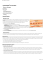
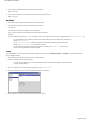
The Pre-Installation Checklist helps you prepare and plan the CommServe® software and MediaAgent Installation.
COMMCELL® ARCHITECTURE OVERVIEW
NETWORK REQUIREMENTS
Domain Name Server (DNS) Environment
WINS or Other Non-DNS Environment
GENERAL HARDWARE CONFIGURATION
Libraries, Drives, and Media
SCSI Cabling and Adapters
DRIVER CONFIGURATIONS
Windows
Solaris
HP-UX
AIX
Tru64
NetWare
Linux
HARDWARE CONFIGURATION GUIDELINES - DIRECT-ATTACHED LIBRARIES
SCSI Ports and SCSI Targets
Single SCSI Configuration Guidelines
Multiple SCSI Configuration Guidelines
Shared Library SCSI Configuration Guidelines
Shared Library SCSI Configuration Guidelines
HARDWARE CONFIGURATION GUIDELINES - DIRECT-ATTACHED SHARED LIBRARIES
Shared Library Setup
HARDWARE CONFIGURATION GUIDELINES - LIBRARIES ATTACHED TO A SAN
The Basic SAN Setup
SAN Addressing Overview
SCSI-LUN Mapping Guidelines for SAN Libraries
SCSI Target Guidelines
Fibre Channel LUN Guidelines
Multiple Router, Single Library Configuration
Avoiding Common Errors
SAN Configuration Summary
REQUIREMENTS FOR CONFIGURING OPTICAL LIBRARIES
HARDWARE CONFIGURATION GUIDELINES - STK LIBRARIES ATTACHED TO ACSLS SERVER
Direct-Attached Library Configuration
DDS Configuration
HARDWARE CONFIGURATION GUIDELINES - ADIC LIBRARIES ATTACHED TO SCALAR DISTRIBUTED LIBRARY
CONTROLLER (SDLC)
Page 1 of 29
Pre-Installation Checklist
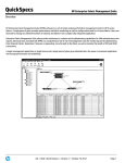
Software Requirements
Hardware Requirements
Page 2 of 29
Pre-Installation Checklist
CommCell® Overview
TABLE OF CONTENTS
Introduction
Client Agents
iDataAgents
Archive Management Agents
ContinuousDataReplicator Agent
Storage Resource Management (SRM)
Common Technology Engine
CommServe®
MediaAgents
CommCell® Console
CommCell Installations
INTRODUCTION
The software provides a powerful set of storage management tools that help you move and manage your
critical data. These tools enable you to store and retrieve data associated with computer systems in your
enterprise.
The system consists of integrated software modules which can be grouped together in a CommCell®
configuration. Each CommCell configuration consists of the following main components:
z
z
One or more of the following Client Agents:
{
iDataAgents that perform the backup and restore operations
{
Archive Management Agents which includes agents for Migration Archiving and Compliance
Archiver agents
{
ContinuousDataReplicator to perform data replication from a source Client to a destination Client
{
Storage Resource Manager (SRM) Agents for analyzing and reporting of information on local storage resources.
Common Technology Engine (CTE) components consisting of:
{
One CommServe®
{
One or more MediaAgents
Once installed and configured, these CommCell elements can be controlled and monitored from a single unified CommCell Console.
CLIENT AGENTS
Client Agents are software modules that perform data protection and data recovery operations for specific operating systems or applications. Multiple agents
may be used to protect all types of data residing on a computer. The following sections provide a brief description of each of these Client Agents.
iDATAAGENTS
iDataAgents are software modules that are used for backing up and restoring data. The system provides a variety of iDataAgents, each one designed to handle
a different kind of data. If a given computer has two or more types of data, it requires one iDataAgent for each data type. For example, to secure all the data
on a computer where a Microsoft Exchange Server resides, you would need the following iDataAgents:
z
One Windows File System iDataAgent to back up the computer’s file system.
z
One Microsoft Exchange Database iDataAgent to back up the database.
In the CommCell® Console, such a configuration would appear as two iDataAgents on a client computer.
ARCHIVE MANAGEMENT AGENTS
This includes 2 types of Agents. They are:
z
MIGRATION ARCHIVER AGENTS
Migration Archiver Agents are software modules that are responsible for periodically moving unused or infrequently used data on their host computers to
secondary storage, thereby reducing the size of data on the primary storage. The system provides several Agents, each one designed to handle a different
kind of data. Migration Archiver Agents reduce the duration of backup windows by reducing the amount of data to be backed up by an iDataAgent.
z
COMPLIANCE ARCHIVER AGENTS
Compliance Archiver Agents are software modules that are designed for long term storage and indexing of data to meet security and compliance standards.
The primary function of Compliance Archiver Agents is to preserve data outside of the operational environment. Compliance Archiver removes the data from
the source client once it has been archived and/or indexed. In this way, large amounts of data can be stored, for example, and reviewed at a later time.
Page 3 of 29
Pre-Installation Checklist
CONTINUOUSDATAREPLICATOR AGENT
ContinuousDataReplicator (CDR) agents are software modules that provide protection of application data and file systems, by replicating data from a source
computer to a destination computer in nearly real-time. High availability of protected data in a consistent state is accomplished through the creation of
Recovery Points, using snapshots created on the destination computer, which can be mounted, made available as shares, or recovered using Copyback. In
addition, backups can be made from the snapshots of file system data or application data in a consistent state for point-in-time recovery.
STORAGE RESOURCE MANAGEMENT (SRM)
SRM software provides the ability to discover, identify, and track available storage resources such as disks, file systems, and network shares to provide detailed
analysis in the form of reports and summaries. SRM software consists of the SRM Server which provides the reporting engine that obtains the data from the
various SRM Agents which are client agents that collect data from the various operating systems and applications.
COMMON TECHNOLOGY ENGINE
Common Technology Engine consists of software modules that provide the necessary tools to manage
and administer the Client Agents and also manage the storage media associated with the CommCell®
configuration. The following sections describe the components of the Common Technology Engine.
COMMSERVE®
The CommServe® Server ties the CommCell® components together; it is the coordinator and
administrator of the CommCell component. The CommServe Server communicates with all agents in the
CommCell to initiate data protection, management and recovery operations. Similarly, it communicates
with MediaAgents when the media subsystem requires management. The CommServe Server maintains a
database - also referred to as the CommServe Database Engine - containing all the information relating
to the CommCell configuration.
MEDIAAGENTS
The MediaAgent transfers data between the client computer(s) and the storage media. Each MediaAgent communicates locally or remotely to one or more
storage devices, which contains the storage media. The system provides support for a wide variety of storage devices.
COMMCELL® CONSOLE
The CommCell Console is the graphical user interface that allows you to control and manage CommCell group. The CommCell Console can be run in two ways:
z
As a stand-alone application, which can be installed directly on any computer that can communicate with the CommServe® storage manager.
z
As a remote web-based application using Java Web Start, which allows you to remotely access the CommCell Console using the web browser.
COMMCELL INSTALLATIONS
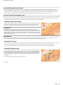
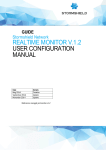
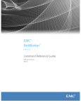
The entire software is modular and can reside on the same and/or separate computers depending on your
needs. Some administrators may have a dedicated CommServe computer and a dedicated MediaAgent
computer. Others may want to back up the file system data on the CommServe Server and therefore
install the client software on the CommServe computer as well. Still others may use the same computer
to serve as the CommServe, MediaAgent, and a client. The software supports any and all of these
configurations.
The illustration provides an example of CommCell Architecture.
Back to Top
Page 4 of 29
Pre-Installation Checklist
Network Requirements
TABLE OF CONTENTS
Overview
Domain Name Server (DNS) environment
Multi-Homed CommCell® Computers
WINS or other Non-DNS Environment
Reverse Lookup
Enabling Reverse Lookup
Internet Protocols
Important Considerations
OVERVIEW
All CommCell® computers (i.e., CommServe, MediaAgent, and Client computers) must be connected via a network configured with TCP/IP protocol. To ensure
each computer can resolve the names of other CommCell computer members and therefore communicate, we offer the following guidelines.
DOMAIN NAME SERVER (DNS) ENVIRONMENT
A DNS environment provides a centralized means of resolving computer names with their corresponding IP addresses. Refer to your operating system
documentation for information on how to establish and manage DNS.
MULTI-HOMED COMMCELL® COMPUTERS
A multi-homed computer is one that has two or more network interface cards (NICs). To ensure proper name/IP address resolution within the CommCell
computer, it is necessary to uniquely name each NIC in the DNS. For example, assume there is a computer whose computer name is amber and fully qualified
host names are amber1.company.com and amber2.company.com respectively. This computer has two NICs with the following IP addresses:
z
First NIC: 150.128.4.78
z
Second NIC: 150.128.6.32
To ensure that both interfaces can be resolved, define unique names within DNS, such as:
z
amber1.company.com 150.128.4.78
z
amber2.company.com 150.128 6.32
If a computer name resolves to multiple IP addresses, the software will automatically use the first IP address
resolved. However, if that first IP address becomes unreachable, the software will not be able to reach the computer
using the other IP addresses in the list. In such scenarios, it is recommended that a hosts file be created with all the
computer's reachable IP addresses included.
WINS OR OTHER NON-DNS ENVIRONMENT
If your network does not have DNS lookup or some other name resolution facility, the CommServe® manager will provide the names and IP addresses of all
the members in the CommCell® group. The fully qualified computer name and IP address of the CommServe manager is stored in the hosts file of each
CommCell member. The hosts file in the CommServe computer, in turn, stores the fully qualified computer name and IP addresses of all the members in the
CommCell, thereby providing the lookup facility to all the members in the CommCell group. Depending on the operating system on your computer, the hosts
file is located in one of the following directories:
z
On a Windows computer, the hosts file is located in %SystemRoot%\system32\drivers\etc directory. (%SystemRoot% is the Windows installation directory
on your system.)
z
On a computer with a Unix operating system, the hosts file is located in the /etc/inet directory.
During installation of each CommCell member, the install program attempts to resolve the name of the CommServe manager to an IP address. If the resolution
fails, the installation prompts you to enter the IP address of the CommServe computer.
Proper name/IP address resolution is essential to reliable network communications.
REVERSE LOOKUP
Prior to performing any installation, ensure that the hostname and the fully qualified domain name are reachable from the CommCell network, and the IP
Addresses/Host Names are resolved correctly using the DNS System.
Computers in a network use the Domain Name System to determine the IP address associated with a host/domain name. This process is also known as forward
DNS resolution. Reverse DNS lookup is the inverse process, the resolution of an IP address to its designated host/domain name. For a proper network
Page 5 of 29
Pre-Installation Checklist
communication, the IP Address to Host Name resolution and Host Name to IP address resolutions are essential.
If reverse DNS lookup is not enabled on a client computer, it will not be able to communicate with the remote computer by using the host name.
Use the following steps to perform a reverse lookup on an IP address:
1.
Logon to the client computer as an Administrator.
2.
Click Start, and then click Run.
3.
In the Open box, type cmd, and then click OK.
4.
From the command prompt, run the following command:
nslookup <remote_computer_ip_address>
Example:
C:\administrator.idclab\nslookup 172.xxx.xxx.244
Server: ingpdc01.gp.cv.company.com
Address: 172.16.xxx.xxx
Name: faraday.gp.cv.company.com
Address: 172.xxx.xxx.244
In the above example, the first section specifies the server and the IP address of that server that provided you with the domain name, and the second section
shows the host name associated with the IP address that you typed with nslookup command.
If the DNS service is not running on the setup, the above command returns one of the following error messages:
No Response from Server
Timed Out
No Records
Server Failure
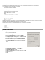
ENABLING REVERSE LOOKUP
Use the following steps to enable Reverse DNS lookup on a client computer:
1.
2.
z
Logon to the computer as an Administrator.
z
Click Start, click Control Panel and then select Network and Internet.
z
Click Network and Sharing Center.
z
Under Tasks, Select Manage network connections.
z
Right-click the Local Area Connection icon, and then click Properties.
z
On the Local Area Connection Properties dialog box, select Internet Protocol
Version4 (TCP/IPv4), and then click Properties.
z
If you have a DHCP Server in your network environment, then select Obtain DNS
server address automatically. Else, select Use the following DNS server
addresses and follow the below steps:
{
In the Preferred DNS server box, type the IP Address of the DNS server.
{
In the Alternate DNS server box, type the IP Address of the alternate DNS
server.
z
Click Advanced.
z
On the Advanced TCP/IP Settings dialog box, click the DNS tab.
z
Click Append these DNS suffixes (in order).
z
Click Add, in the Domain suffix box, type the Domain suffix, and then click Add.
Repeat this step to add all the DNS suffixes in order.
z
Click OK, and then click OK.
z
Click OK.
Page 6 of 29
Pre-Installation Checklist
In case the DNS is not configured or not supported, then the client computer will not be able to perform IP/Name resolution and will not be able to
communicate with the remote computers by using the host names. You can overcome this temporarily by adding the IP addresses and the fully qualified
domain names in the host file of the client computer. It is not recommended to add Hosts file entries as these create communications control points that may
impact other server operations and are difficult to maintain and manage. These should be used only as temporary solutions until the larger network or DNS
issues can be resolved. You can use the following steps to add entries to the host file of the client computer with Windows operating system:
1.
Logon to the computer as an Administrator.
2.
Click Start, and then click Run.
3.
In the Open box, type drivers, and then click OK.
4.
Double-click etc folder, open hosts file with Notepad, and then type the IP address, the fully qualified domain name and the host name of the remote
computer. You can add additional entries on separate lines. Save the hosts file after adding the entries.
Example:
172.32.xxx.xxx dbwin1.idclab.loc dbwin1
172.14.xxx.xxx dbwin2.idclab.loc dbwin2
Similarly, to enable reverse lookup on a remote computer, repeat step 1 through step 3 for adding IP address of the client computer in the hosts file of the
remote computer.
For more information, see: http://technet.microsoft.com/en-us/library/cc780585(WS.10).aspx
For a Unix computer, the entries should be added in the host file located under etc folder.
INTERNET PROTOCOLS
CommCell® computers can operate on the following Internet Protocol (IP) versions:
z
IPv4 on all Windows, Unix, and Novell client computers.
z
IPv6 on the following Windows and Unix computers (See Support below for more information.)
IMPORTANT CONSIDERATIONS
The CommServe® computer requires IPv4 to obtain permanent licenses. However, the CommServe® computer can have both IPv4 and IPv6 enabled using
multiple NIC cards. If the client computers in the CommCell® use the IPv6 protocol, the CommServe and MediaAgent must also use the IPv6 protocol.
CONFIGURATION
To enable CommCell® functionality for Windows computers on an IPv6 network, you must use the following registry keys:
z
nOverridePreferredIPFamily - This key provides the capability to install CommCell components on computers in an IPv6 environment. This key must be
manually created on each computer in the CommCell group prior to installing any software components.
Note that this key only provides IPv6 support for the duration of the software installation.
z
nPreferredIPFamily - This key is provided with the software and allows you to operate CommCell components in an IPv6 environment beyond the software
installation process. This key must be configured on each computer in the CommCell group after the software has been installed.
Page 7 of 29
Pre-Installation Checklist
To enable CommCell functionality for Unix computers on an IPv6 network, you must perform the following:
z
Add the following to the cvpkgadd command:
-display-interface-family [nPreferredIPFamily]
For example, if you wish to apply both IPv4 and IPv6 support, you would add the following to the cvpkgadd command:
-display-interface-family 0
Note that this key only provides IPv6 support for the duration of the software installation.
z
nPreferredIPFamily - This key is provided with the software and allows you to operate CommCell components in an IPv6 environment beyond the software
installation process. This key must be configured on each computer in the CommCell group after the software has been installed.
COMMCELL CONSOLE CONSIDERATIONS
z
If a CommServe server has both IPv4 and IPv6 protocols enabled, the CommCell® Console will always obtain an IPv4 address. If you wish to obtain and
connect with an IPv6 address, the following parameter must be added to the java/javaw command:
-Djava.net.preferIPv6Addresses=true
For example:
"C:\Program Files\Java\jre1.6.0\bin\javaw.exe" -jar cv.jar cranberry 8401 -oemid=1 -Djava.net.preferIPv6Addresses=true
Note that this configuration is supported for the CommCell Console as a stand-alone application only. If you are running the CommCell Console as a remote
web-based application, you will always obtain an IPv4 address.
z
To run the CommCell Console as a Remote Web-Based Application in an IPv6 environment, the web alias must include either the IPv6 address or a host
name that resolves to the IPv6 address.
MACINTOSH FILE SYSTEM CONSIDERATIONS
z
By default, the software installation program will not display IP addresses that are not reverse-resolvable to the a host name in the interface list. To display
such IP addresses, create the following empty file:
/tmp/cvpkgadd_unlock_ipaddress
OUTLOOK ADD-IN CONSIDERATIONS
z
To perform stub recalls using the Outlook Add-In in an IPv6 environment, the ipfamilypref registry key must be configured to accept the IPv6 protocol.
This key must be configured on each computer on which Outlook Add-In is installed.
FILE ARCHIVER CONSIDERATIONS
z
It has been seen that a Windows computer may crash with a blue screen when accessing a file under the following conditions:
{
the file resides on a Celerra file server
{
the file has offline attributes set
{
the services handling offline file restores is disabled or shut down
{
the client Windows computer has IPv6 installed and enabled
Therefore, it is recommended that the services handling stub file restores are running before accessing offline stub files on a Celerra file server from a
Windows computer with IPv6 enabled.
z
FPolicy with NetApp ONTAP is not supported with IPv6 on Microsoft Windows Server 2008 platforms.
z
If the File Archiver Agent is installed on a computer using the IPv4 protocol and the client computer is using the IPv6 protocol, it is recommended that the
nPreferredIPFamily registry key be created on the client computer with the value set to 1. This will ensure connections between the two computers are not
disrupted during stub recalls.
SUPPORT
IPv6 is not supported for the following:
z
1-Touch client recoveries
z
Command Line Interface
z
Content Indexing and Search
z
Data Classification on Unix platforms
z
NDMP Remote Server (when backup up a file server that does not support NDMP IPv6)
z
NetWare MediaAgent
z
NetWare File System iDataAgent
z
Novell Directory Services (NDS) iDataAgent
z
Novell GroupWise iDataAgent
Page 8 of 29
Pre-Installation Checklist
z
Unix computers running HP-UX 11.00
Additionally, consider the following:
z
IPv6 support for AIX 5.3 and above may require use the of /etc/hosts for IPv6 name resolution.
z
IPv6 support for Tru64 OSF1 Release 5.1A requires the use of /etc/ipnodes for IPv6 name resolution.
z
IPv6 support for HP-UX 11.11 requires the installation of the Transport Optional Upgrade Release (TOUR) 2.5 and OS patch PHCO29328.
z
For Linux computers, only varieties with a glibc of 2.3 or 2.4 are supported with IPv6.
z
For Solaris computers, only Solaris 9 and above are supported with IPv6.
z
For Windows computers, only Microsoft Windows Server 2003 varieties and above are supported with IPv6.
z
The Optimize for Concurrent LAN Backups option is not supported for AIX MediaAgents using the IPv6 protocol.
Back to Top
Page 9 of 29
Pre-Installation Checklist
General Hardware Configuration
TABLE OF CONTENTS
Overview
Libraries, Drives, and Media
SCSI Cabling and Adapters
OVERVIEW
You can avoid many installation problems by properly setting up your libraries and media drives. Read the appropriate sections before configuring your storage
libraries.
Each tape library and drive can be directly attached to one or more MediaAgents via SCSI buses or remotely connected via a Storage Area Network (SAN). In
addition, drives can be remotely accessed through a NetApp filer using the NDMP protocol. In any case, in order to manage the media changers and drives
within a CommCell® group, the MediaAgent must know the SCSI address or NetApp filer drive address of each device, the MediaAgent that controls the device,
and the library to which the device belongs.
You must configure libraries and drives when:
z
You install a new MediaAgent, library, or drive.
z
The existing SCSI configuration changes and the MediaAgent cannot reconfigure them automatically.
We strongly recommend you to verify and ensure that proper hardware zoning of tape drives be implemented,
especially when you have HBA failover implemented in your environment. For more information on zoning of HBA
failover, contact your HBA software vendor.
LIBRARIES, DRIVES AND MEDIA
Contact your software provider for a list of storage devices (libraries, drives, media and SAN devices) and compatible SCSI cards supported by MediaAgents.
If the storage devices are attached to NAS filers, or UNIX computers, (Solaris, HP-UX, AIX or Tru64) refer to the appropriate vendor documentation for a list of
compatible devices.
SCSI CABLING AND ADAPTERS
The software supports the use of the following general types of SCSI based devices:
z
Single-ended
z
Differential
z
LVD (low voltage differential)
z
HVD (high voltage differential)
Each type requires its own set of adapters, cabling, devices (i.e., media drives) and terminators. Because they are electrically incompatible with each other, you
must not mix them (e.g., by connecting a single-ended adaptor, cable, or terminator to a differential drive).
Back to Top
Page 10 of 29
Pre-Installation Checklist
Driver Configurations
TABLE OF CONTENTS
Overview
Windows
Solaris
HP-UX
AIX
Tru64
NetWare
Linux
OVERVIEW
Once you’ve cabled and configured the storage media, you must verify that the drivers are ready and working properly on the computer in which you wish to
install the MediaAgent. This is performed before installing the MediaAgent software. The following steps, although not conclusive, should help you to identify
most of the common configuration problems.
Ensure that all SCSI adapter and tape device drivers are installed.
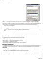
WINDOWS
The following steps explain common configuration problems for Windows 2000, Windows 2003 Server, and Windows 2008 Server.
You can access the Computer Management window using the following options from the Start menu –
Programs, Administrative Tools, Computer Management.
1.
2.
In the Computer Management window, make sure the attached media changer, tape or optical drives for the library are listed.
Expand tape or disk drives and select each drive, right click and select Properties to verify that the drive information is correct. Check the Device Status
and ensure that the device is working properly.
If drives are not listed, detect the device and install the appropriate driver. For more information on this task, refer
to the user manual provided by the manufacturer of your library and drive.
For devices using the iSCSI and Storport drivers make sure that the medium changer for the library is enabled in the Windows Computer Management
Page 11 of 29
Pre-Installation Checklist
window. For all other drivers we recommend that the media changer is disabled in the Windows Computer Management window.
1.
From the Computer Management window select Device Manager in the left window panel and expand Medium Changers in the right window panel.
2.
Right-click the library with the media changer and select Enable or Disable as appropriate.
If you are starting the computer for the first time after installing the MediaAgent, ensure that the Removable Storage Management (RSM) is disabled.
1.
Do one of the following:
{
Disable and stop RSM service from the Service pane.
{
If the RSM service cannot be disabled, verify that all targeted libraries and drives are absent from or disabled in the list under the storage/removable
storage/ physical locations folder.
SOLARIS
1.
Ensure that the appropriate drivers for the SCSI/HBA/FC card are installed and working properly.
2.
Ensure that all the devices (libraries and drives) are connected properly.
HP-UX
HP-UX MediaAgent requires the kernel modules stape, sctl and schgr to be loaded, in order to use tape libraries. Install these kernel modules using the
following steps:
1.
At the Unix prompt type sam.
2.
In the System Administration Manager dialog, select Kernel Configuration and press <Return>.
3.
In the Kernel configuration dialog, select Drivers and press <Return>.
4.
Select stape.
5.
From the ACTION menu choose add drivers to kernel.
6.
Repeat steps 4 and 5 to load sctl and schgr kernel modules.
7.
Choose Process New Kernel.
8.
At the prompt select the option to reboot the system.
AIX
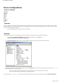
In AIX MediaAgents, you can view a list of SCSI devices and tape drives using either the smit or lsdev command. You can also use the wsm tool, which is a
graphical administrative tool.
USING SMIT
1.
At the Unix prompt type smit.
Viewing SCSI Adapters
2.
In the System Management Interface Tool dialog box, select Devices, SCSI Adapter and then List All SCSI Adapters.
A list of all SCSI adapters available in the system are displayed.
Viewing Tape Drives
3.
In the System Management Interface Tool dialog box, select Devices, Tape Drives and then List All Defined Tape Drives. A list of all the tape
drives attached to the system are displayed.
USING LSDEV
1.
At the Unix prompt type:
lsparent -C -k scsi
A list of all SCSI adapters available in the system are displayed.
2.
At the Unix prompt type lsdev -C -c tape.
A list of all the tape drives attached to the system are displayed.
TRU64
1.
Ensure that all the devices (libraries and drives) are connected properly.
Page 12 of 29
Pre-Installation Checklist
2.
Use the following command to list the devices attached to the system:
hwmgr -show scsi
3.
If you do not see the devices, use the following command to auto-detect the devices:
hwmgr -scan scsi
NETWARE
1.
2.
Ensure that all the devices (libraries and drives) are connected properly.
Use the following command to list the devices attached to the system:
list devices
A list of devices connected to the NetWare server are displayed.
If you do not see the devices, use the following command to detect the devices:
nwconfig
If you have a Qlogic card and use the /IGNCFG command to see the devices edit the load command for the Qlogic HAM with /IGNCFG in Startup.ncf file.
It is recommended that you unload any Custom Device modules (CDMs) that may be loaded, before configuring the
libraries. (e.g., nwtape.cdm)
Use the list storage adapters command to determine the CDMs that are loaded and then use the unload
command (e.g., unload nwtape.cdm) to unload these modules.
It is also recommended that the list of unload commands are included in the autoexec.ncf, to prevent these
modules from being loaded after subsequent reboots.
LINUX
In Linux MediaAgents, you can view a list of SCSI devices and tape drives using either the Hardware Browser or Terminal to view the attached devices.
Using the Hardware Browser
1.
Ensure that all the devices (libraries and drives) are connected properly.
2.
Install the necessary drivers for the SCSI devices.
For example, using GNOME, you can access the Hardware Browser using the following options: From the Start menu
– System, Hardware Browser.
3.
On a Linux computer you can view the libraries and drives from the Hardware Browser.
4.
Click on the SCSI devices to view a list of SCSI adapters available in the computer.
5.
Click on Tape Drives to view a list of tape drives attached to the computer.
Page 13 of 29
Pre-Installation Checklist
USING THE TERMINAL
1.
Ensure that all the devices (libraries and drives) are connected properly.
2.
Install the necessary drivers for the SCSI devices.
3.
Navigate to the following folder in the Terminal window:
/proc/scsi
The location of this file may vary in the various Linux Kernel versions.
4.
Open the following file:
scsi
5.
The SCSI devices attached to the computer should be listed.
Page 14 of 29
Pre-Installation Checklist
Hardware Configuration Guidelines - Direct-Attached Libraries
TABLE OF CONTENTS
Overview
SCSI Ports and SCSI Targets
Single SCSI Configuration Guidelines
Single Library Setup
Multiple SCSI Configuration Guidelines
Single Library, Two Stand-Alone Drives Setup
Single Library Setup
Multiple Library Setup
OVERVIEW
The sections that follow present guidelines for configurations in which libraries are physically attached to the MediaAgents that control them. For SAN
configuration guidelines, see Hardware Configuration Guidelines - Libraries Attached to a SAN.
SCSI PORTS AND SCSI TARGETS
When you install a MediaAgent that is attached to one or more tape libraries, the MediaAgent detects all attached media changers and media drives. Similarly,
when you attach a new library to one or more MediaAgents, the system maps the library and its drives. The system attempts to identify the library to which
each device belongs and the device’s physical address within that library. Drives belonging to a shared library whose media changer is controlled by another
MediaAgent are detected as stand-alone drives. You must manually map such drives to the correct library by using the Library and Drive Configuration
window.
To automate the detection process, the MediaAgent assumes that the SCSI configurations (i.e., SCSI port and target numbers) of media drives and media
changers are set in a certain manner. If they are set according to the convention, then the detection process correctly associates the SCSI target of each drive
to the drive’s physical position, provided that the MediaAgent that controls the drive also controls the media changer of the same library. If the SCSI
configuration is not set according to the convention, or if you are configuring drives and the related media changer is controlled by a different MediaAgent, you
may manually map the drives using the Library and Drive Configuration window or use exhaustive detection. (For information on using the Library and
Drive Configuration window, see Library and Drive Configuration.)
Most library and drive manufacturers strongly recommend against using the embedded SCSI controller on a server’s
system board to drive the media changer or drives. For this reason, all libraries and drives should be attached to the
MediaAgent computer via dedicated SCSI cards.
The following hardware configuration guidelines are intended to help you avoid the manual mapping process where possible. If you follow these guidelines, the
MediaAgent will detect drives in their physical order and associate them with their proper libraries. While other SCSI configurations can result in a properly
working system, we strongly recommend that you follow these guidelines and thus avoid common errors.
SINGLE SCSI CONFIGURATION GUIDELINES
Observe the following guidelines if your libraries and drives are connected to a MediaAgent via only one SCSI port.
When you install a new library, you must set a SCSI target of the media changer and each drive within the library.
See the manufacturer’s documentation for specific instructions.
z
If you plan to attach stand-alone drives, allocate the lowest targets to the stand-alone drives, reserving the higher target numbers for the media changers
and their related drives for regular libraries.
z
If you plan to attach a drive whose media changer is controlled by a different MediaAgent, see Hardware Configuration Guidelines - Direct-Attached Shared
Libraries.
z
It is recommended that the media changer have a target lower than the targets of its drives. Otherwise, drives may be associated with the wrong library or
incorrectly detected as stand-alone drives. (By convention we assign it to target 0 in single library setups, although a higher number is acceptable.)
Stand-alone drives do not have media changers.
z
When setting the SCSI targets, it is recommended that you assign SCSI target numbers in ascending order in accordance with the physical drive location.
The drive with the lowest physical address gets the lowest SCSI target. The drive with the highest physical address gets the highest SCSI target. Drives in
between are assigned sequentially. A good convention to use, when possible, is to set the library media changer to 0, the first drive to target 1, the second
drive to target 2 and so on. This can make it easier to identify the drives later.
Physical drive locations are numbered differently depending on the library. The first drive in one library may be 0
while in another library it may be 1. See the manufacturer’s documentation for details on your library.
Page 15 of 29
Pre-Installation Checklist
z
Do not assign SCSI target 7 to a drive as this is normally reserved for the SCSI adapter. For wide SCSI (68-pin) installations, 15 targets are available.
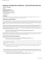
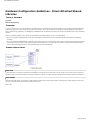
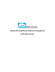
SINGLE LIBRARY SETUP
SCSI PORT
In this configuration, a single SCSI port (i.e., port 1) connects the MediaAgent to the library and its media drives, four in this case. The port number can vary
from system to system and depends on whether any other SCSI devices are already installed. For example, your system may have a CD-ROM drive assigned to
a target on SCSI port 0.
SCSI TARGET
When assigning SCSI targets, we started at target 0 and went in ascending order, matching the target number to the physical drive location. We could have
started at a higher number, provided we kept an ascending sequence (e.g., 2, 5, 6, 8, and 9).
MULTIPLE SCSI CONFIGURATION GUIDELINES
Observe the following guidelines if your libraries and drives are connected to a MediaAgent via two or more SCSI ports.
z
Observe all of the single SCSI configuration guidelines.
z
If you have two or more SCSI ports attached to your MediaAgent, try to assign unique SCSI targets to each device, even for devices on different SCSI ports.
z
Always associate the media changer with the lowest drive in its library.
z
You can attach two or more stand-alone drives to a MediaAgent. If you plan to attach stand-alone drives, allocate the lowest SCSI port numbers to those
Doing so can make it easier to identify the drives later, should that become necessary.
drives, reserving the higher port numbers for any libraries.
The following illustrations provide several scenarios that demonstrate each of these guidelines.
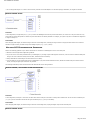
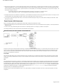
SINGLE LIBRARY, TWO STAND-ALONE DRIVES SETUP
SCSI PORT
In this configuration, SCSI port 1 connects to two stand-alone drives. SCSI port 2 connects to a library and its media drives. We use the lower numbered port
(i.e., port 1) for the stand-alone drives and the higher numbered port (i.e., port 2) for the library.
SCSI TARGET
When assigning SCSI targets, we started at target 0 and went in ascending order, keeping all targets unique across the SCSI ports.
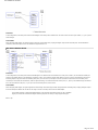
SINGLE LIBRARY SETUP
Page 16 of 29
Pre-Installation Checklist
SCSI PORT
In this configuration, two SCSI ports connect the MediaAgent to the library and its media drives. We must connect the lower port number (i.e., port 1) to the
media changer.
SCSI TARGET
When assigning SCSI targets, we started at target 0 and went in ascending order, keeping all targets unique across the SCSI ports. We maintained this
consistency across SCSI port 2 where we started the target numbers at 3.
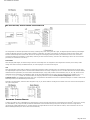
MULTIPLE LIBRARY SETUP
SCSI PORT
In this configuration, five SCSI ports connect the MediaAgent to two libraries with two media drives on each port. As before, we connected the lowest port
number to the media changer in the first library and drives 1 and 2. (We could have chosen either library to be first.) Then we connected the next ports in
ascending sequence by port number to ascending drive pairs: port 2 to drives 3,4 and port 3 to drives 5,6. When all the drives in the first library were
connected, we connected the second library. With two ports remaining, we connected the lower number port (i.e., port 4) to the media changer and drives 1
and 2. We connected the last port (i.e., port 5) to the two remaining drives, drives 3 and 4.
SCSI TARGET
When assigning SCSI targets, we again assigned the media changer the lowest target number and proceeded in ascending order, keeping all targets unique
across the SCSI ports. Notice that we did not use target 7 as this is normally reserved for the SCSI adapter.
This example assumes a wide SCSI implementation. If we had used narrow SCSI, which only has 7 available
targets, we would have restarted the target numbering sequence on Library 2 using targets 0 through 4.
Back to Top
Page 17 of 29
Pre-Installation Checklist
Hardware Configuration Guidelines - Direct-Attached Shared
Libraries
TABLE OF CONTENTS
Overview
Shared Library Setup
OVERVIEW
To help you get the most out of your tape libraries, the software allows you to attach the media changer and drives within a library to different MediaAgents
within the CommCell. The system creates a drive pool for all of the drives within a given library that are attached by a specific MediaAgent. (Although the
library's media changer is attached to one MediaAgent, all MediaAgents that are attached to the library have access to the media changer through centralized
software.)
Observe the following guidelines if your libraries are shared between and attached directly to two or more MediaAgents.
z
If you are configuring a MediaAgent that controls the media changer of a shared library, follow the guidelines described in Single SCSI Configuration
Guidelines.
z
If you are configuring a MediaAgent that is attached to drives within a library, but not the library's media changer, assign the lowest available SCSI targets
to these drives. We recommend that you assign SCSI targets in ascending order in accordance with drive position. If possible, the SCSI target numbers
should match the physical drive location. This will facilitate library and drive administration.
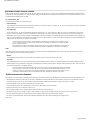
SHARED LIBRARY SETUP
SCSI PORT
In this configuration, one SCSI port connects the first MediaAgent to the library and its media drives. The port number can vary from system to system and
depends on whether any other SCSI devices are already installed. For example, your system may have internal disk drives assigned to targets on SCSI port 0.
SCSI TARGET
When assigning SCSI targets, we assigned the media changer the lowest target number and proceeded in ascending order, keeping all targets unique across
the library. The SCSI targets correspond to the physical drive number.
Back to Top
Page 18 of 29
Pre-Installation Checklist
Hardware Configuration Guidelines - Libraries Attached to a
SAN
TABLE OF CONTENTS
Overview
The Basic SAN Setup
SAN Addressing Overview
SCSI-LUN Mapping Guidelines for SAN Libraries
SCSI Target Guidelines
Fibre Channel LUN Guidelines
Single Router, Multiple Library Configuration
Multiple Router, Single Library Configuration
Avoiding Common Errors
Avoiding Dynamic Address Changes
SAN Configuration Summary
OVERVIEW
Storage Area Networks (SAN) present additional configuration issues, that are discussed in the following sections.
Stop and disable Removable Storage Management (RSM) service on all Windows 2000 on a SAN, which can detect the shared tape/optical drives
that are configured. These include other MediaAgents and even other machines which do not have any components installed. This is a very stringent
requirement as data corruption occurs if both RSM and MediaAgent running on any machine in the SAN access the same drive at the same time.
We strongly recommend that in a SAN based environment, hardware zoning of tape drives be implemented so that only the designated MediaAgents
can detect and control the devices. This will minimize unnecessary monitoring and access to the devices from non-designated machines.
THE BASIC SAN SETUP
A Storage Area Network (SAN) is a Fibre Channel network that is dedicated to carrying backup data. SAN enhances backup and restore performance and eases
congestion on an enterprise's Local Area Network (LAN), freeing it for normal business activities and communication. You can configure your SAN environment
to take advantage of the Dynamic Drive Sharing (DDS) feature to share drives among multiple MediaAgents in a CommCell® group within a SAN environment.
Basic SAN components include:
z
HOST BUS ADAPTER (HBA)
Each computer that is attached to a fibre network needs a special adapter, an HBA, that can send and receive signals across Fibre Channel cables.
z
BRIDGE, ROUTER OR GATEWAY
These pieces of equipment translate fibre signals to signals that can be understood by SCSI devices (fibre-to-SCSI communications) and vice versa. A
gateway can also communicate between a Fibre Channel network and native fibre devices (fibre-to-fibre communications). Bridges, routers, and gateways
are used to connect servers and storage devices to the SAN.
z
HUB
In a Fibre Channel Arbitrated Loop (FC-AL) (see below), the hub is the fault-tolerant center of the network to which servers and storage devices are
connected.
z
SWITCH
In the more complex network environment of switched fibre (see below), the switch is the center of the fabric, or infrastructure, of the network. Servers and
storage devices are connected to the switch, which is more intelligent and has more bandwidth than a hub.
There are two basic SAN configurations:
z
FIBRE CHANNEL ARBITRATED LOOP (FC-AL)
This configuration is logically equivalent to a logical ring of fibre to which all of the devices are connected. FC-AL is implemented by connecting devices to a
hub. Bandwidth and storage resources on the network are pooled and shared by all devices
Page 19 of 29
Pre-Installation Checklist
z
SWITCHED FIBRE
In a switched configuration, virtual loops are established between hosts and backup devices. Each host may have exclusive use of its virtually attached
storage devices.
SAN ADDRESSING OVERVIEW
In order for backup devices to be available to the MediaAgent, the system must know which physical device is mapped to a given SCSI address. When a
MediaAgent is directly attached to a storage device, the SCSI address is determined by the physical SCSI connection. SAN adds a Fibre Channel (FC) network
between the MediaAgent and the SCSI backup device. However, the MediaAgent and the backup device still use the SCSI protocol to communicate across the
FC network. Consequently, the MediaAgent still needs to be able to associate each physical device with a SCSI address.
A SCSI address includes three identifiers. The table below lists the components of a SCSI address and its counterparts in the switched fibre and FC-AL
addressing schemes.
SCSI
FIBRE CHANNEL ARBITRATED LOOP (FC-AL)*
SWITCHED FIBRE (FC-SW)*
Bus
Target
Logical Unit Number (LUN)
Loop
Arbitrated Loop Physical Address (AL_PA)
LUN
Fabric
Port_ID
LUN
* Conceptually, both a loop and fabric represent collections of addressable devices. In practice, this part of the address is generally the same as the port
number of the HBA that connects the host to the FC network.
SCSI-LUN MAPPING GUIDELINES FOR SAN LIBRARIES
See the hardware manufacturer’s documentation for instructions on setting SCSI targets for storage devices and
SCSI-to-FC address mapping for SAN routers.
LUN guidelines must be followed in order for the system to function properly. SCSI target guidelines are
recommendations that can make system administration easier, but they are not requirements.
SCSI TARGET GUIDELINES
Observe the following guidelines when assigning SCSI targets to storage devices attached to a SAN:
z
Assign each media changer to a SCSI target lower than the targets of its drives.
Page 20 of 29
Pre-Installation Checklist
z
When setting the SCSI targets, you should assign SCSI target numbers in ascending order in accordance with the physical drive location. The drive with the
lowest physical address (e.g., Drive 0) gets the lowest SCSI target. The drive with the highest physical address (e.g., Drive 4) gets the highest SCSI target.
Drives in between are assigned sequentially. A good convention to use, when possible, is to set the library media changer to 0, the first drive to target 1, the
second drive to target 2, and so on.
Physical drive locations are numbered differently depending on the library. The first drive in one library may be 0
while in another library it may be 1. See the manufacturer’s documentation for details on your library.
z
If multiple SCSI ports are to be attached to a single library, you should attach the SCSI ports in order of the physical device sequence. For example, connect
z
Try to assign a unique SCSI target to each device, even for devices on different SCSI ports. Doing so can make it easier to identify the drives later, should
the first SCSI port to the media changer and drives 1 and 2; the next SCSI port to drives 3 and 4, and so on.
that become necessary.
FIBRE CHANNEL LUN GUIDELINES
Observe the following guidelines when assigning fibre channel LUNs to storage devices attached to a SAN:
z
Assign each media changer to a LUN lower than the LUNs of its drives. Otherwise, drives may be associated with the wrong library or incorrectly detected as
z
For each router, assign LUNs starting with zero and continue in ascending sequence. Do not skip any numbers in the sequence.
stand-alone drives.
The following illustrations provide several scenarios that demonstrate these guidelines.
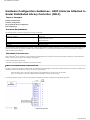
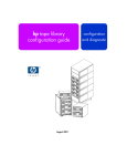
SINGLE ROUTER, MULTIPLE LIBRARY CONFIGURATION
Moving from left to right, the diagram depicts the following: A MediaAgent contains an HBA that connects it, via a fibre channel switch to a SAN router. Within
the fibre network, SAN devices are addressed by fibre channel LUNs, which are set through the LUN mapping interface provided by the manufacturer of the
router. The router is connected via SCSI buses and cables to two libraries. Within the libraries, each device has a SCSI target, which is set via the interface
provided by the manufacturer of the library.
SCSI TARGET
When assigning SCSI targets, target 0 is assigned first with the rest in ascending order. The lowest target within the library is assigned to the library’s media
changer. If the library has additional drives, target 7 would be skipped, because the SCSI controller uses SCSI ID 7 by default, and the assignments continue
with target 8.
LUN
When assigning fibre channel LUNs, we started at 0 and assigned contiguous LUNs in ascending order. The diagram only depicts those aspects of the SCSI and
FC addresses that are commonly configured by the user. The tables below show the complete address translations that are performed by the router between
SCSI addresses (Bus, Target, LUN) and fibre channel addresses (Loop, AL_PA, LUN), and the reverse translations that are performed by the MediaAgent’s HBA.
The left-most SCSI addresses are the ones by which the SAN devices are identified in the Library and Drive Configuration window. See Library and Drive
Configuration for additional information on configuring libraries and drives in the Library and Drive Configuration window. For details on SCSI and FC
addressing schemes, see SAN Addressing Overview above.
Note that values of zero have been assigned to Loop, AL _PA, and the SCSI bus and target in the address on the left. The actual values depend on the SAN
configuration.
Page 21 of 29
Pre-Installation Checklist
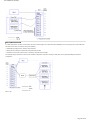
MULTIPLE ROUTER, SINGLE LIBRARY CONFIGURATION
This configuration can maximize performance for a library containing many drives. Moving from left to right, the diagram depicts the following: A MediaAgent
contains an HBA that connects it via a Fibre Channel network to a SAN switch. The switch is connected to two SAN routers. Within the fibre network, SAN
devices are addressed by Fibre Channel LUNs, which are set through the LUN mapping interface provided by the manufacturer of the router. The router is
connected via SCSI buses and cables to a single library containing six drives. Within the library, each device has a SCSI target, which is set via the interface
provided by the manufacturer of the library.
SCSI TARGET
When assigning SCSI targets, we started at target 0 and went in ascending order. We assigned the lowest target within the library to the library’s media
changer. Note that if the library had additional drives, we would skip target 7 and continue with target 8.
LUN
When assigning Fibre Channel LUNs, we started at 0 and assigned contiguous LUNs in ascending order. We restarted LUN numbering with the second router.
The diagram depicts only those aspects of the SCSI and FC addresses that are commonly configured by the user. The tables below show the complete address
translations that are performed by the router between SCSI addresses (Bus, Target, LUN) and Fibre Channel addresses (Loop, AL_PA, LUN), and the reverse
translations that are performed by the MediaAgent’s HBA. The left most SCSI addresses are the ones by which the SAN devices are identified in the Library
and Drive Configuration window. For more information on configuring SAN devices using the Library and Drive Configuration window from the
CommCell Console, see SAN-Attached Libraries. Each router is represented in the addresses on the left as a separate SCSI target. For details on SCSI and FC
addressing schemes, see SAN Addressing Overview above.
Note that in the tables below, values have been assigned to Loop, AL_PA, and the SCSI bus and target in the address on the left. The actual values depend on
the system configuration.
AVOIDING COMMON ERRORS
In setting up a SAN for use by a MediaAgent, the essential goal is to ensure that each physical device is represented in the CommCell® group by one, and only
one, SCSI address, (bus, target and LUN) and that this SCSI address remains consistent through all layers of the SAN, at all times. If a single device is
represented by multiple SCSI addresses, or if multiple instances of a single address for a device exist within the network, resource contention can occur as
different MediaAgents attempt to use the same drive simultaneously.
Page 22 of 29
Pre-Installation Checklist
AVOIDING DYNAMIC ADDRESS CHANGES
A fibre channel address can change at either the AL_PA/ Port_ID level or at the LUN level. In either case, the HBA translated SCSI address of affected devices
changes as well. If the SCSI address of a configured device changes, the MediaAgent will be unable to access the device. The sections that follow tell you how
to maintain address stability within your SAN.
AL_PAS AND PORT_IDS
AL_PAs and Port_IDs can be set in one of two ways:
z
Hard addressing
This addressing scheme requires that you manually set switches on a device to assign it a permanent AL_PA. (A Port_ID includes the AL_PA plus information
about the fabric port to which the device is attached.)
z
Soft addressing
If you use this scheme, AL_PAs are automatically assigned to fibre devices (e.g., routers, gateways, HBAs, etc.) when they are attached to the network.
However, if devices are added or removed, the addresses of other devices in the network may be reassigned, rendering these devices inaccessible to the
MediaAgent. If the AL_PA of a router changes, all attached libraries become inaccessible to the MediaAgent. Note that soft addresses may be assigned even
when you use hard addressing. If the switches on two devices are set for the identical AL_PA, then the first device detected by the network is assigned that
address, while the second device is assigned a soft address.
To ensure that AL_PAs won’t change, use hard addressing and make sure that each device is assigned a unique
AL_PA. To ensure that Port_IDs won’t change, follow the AL_PA guidelines. In addition, do not change the fabric
ports of configured devices.
Some gateways do not work well with fibre channel switches unless you enable soft addressing. Also some of the
SAN gateways do not allow you to disable soft addressing. Enable soft addressing in both these circumstances.
LUNS
Fibre channel LUNs are set by bridges, routers and gateways, which translate the SCSI addresses (SCSI port, target, and LUN) of attached devices to fibre
channel addresses. Routers have two addressing modes:
z
Manual
This addressing scheme requires that you manually set the LUN for each device that is attached to the router.
z
Automatic
In this addressing scheme, the router automatically assigns LUNs to attached devices. However, if devices are added or removed, the addresses of other
attached devices may be reassigned. Consequently, the MediaAgent is unable to access the device. Note that LUNs must start from zero. They must also be
sequential and contiguous (not skipping numbers).
To ensure that the LUNs of devices attached to a router won’t change, use manual addressing. Make sure that each
device is assigned a unique LUN, and that LUNs start from zero and are sequential and contiguous. When you first
configure your SAN, you may want to use automatic addressing to ensure that LUNs meet these criteria. You can
then switch to manual mode to set the same addresses that were automatically assigned by the router.
SAN CONFIGURATION SUMMARY
The following items summarize the SAN configuration issues that can impact the ability of the MediaAgent to successfully detect and use SAN storage devices:
z
All MediaAgents attached to a SAN must use the same or compatible brand and model HBA, and where possible, the same driver and firmware revisions;
this is also true for all routers. This ensures that the same fibre channel-to-SCSI address translation is used for all devices in the SAN.
z
The latest available version of firmware and device drivers must be used.
z
Use hard addresses rather than soft addresses to ensure that AL_PAs and Port_IDs will not change.
z
Make sure that each device is assigned a unique AL_PA.
z
Do not change the fabric port of configured devices that are attached to a switched network.
z
Be careful to preserve the sequential, contiguous order, starting at 0 (assumed by operating systems) when you set AL_PAs in manual mode.
z
Use manual addressing mode to prevent SAN routers from changing LUNs when the SCSI configuration changes.
z
For easier system administration, follow SCSI configuration guidelines above when setting SCSI targets for storage devices.
Back to Top
Page 23 of 29
Pre-Installation Checklist
Requirements for Configuring Optical Libraries
The Optical Library must be attached to a MediaAgent running on a Windows computer. The library can be connected through either an Adaptec or a Qlogic
ultra SCSI differential card. We recommend to connect no more than four drives per SCSI card. Observe the following guidelines while configuring this library:
z
The latest firmware version should be loaded to the library.
z
Use all optical drives with the same speed and optical cartridges of same capacity.
z
Do not set the data-protect tab on any cartridge. Setting the data-protect tab will fail all operations on the cartridge.
z
Disable RSM as described in Driver Configurations.
Page 24 of 29
Pre-Installation Checklist
Hardware Configuration Guidelines - STK Libraries Attached to
ACSLS Server
TABLE OF CONTENTS
Overview
Direct-Attached Library Configuration
Direct-Attached Library Configuration with SN6000
DDS Configuration
DDS Configuration with SN6000
OVERVIEW
StorageTek libraries controlled by an ACSLS Server can be configured. Such ACSLS controlled StorageTek libraries can be shared between:
z
Multiple MediaAgents in a CommCell® group
z
Multiple CommCell groups, or
z
CommCell groups and others applications like Vault 98, etc.
Note that the ACSLS server computer can also be a component (either a MediaAgent or an agent) of the CommCell group. The system can share a StorageTek
(STK) library with Vault98 or other applications that are accessing the STK library via ACSLS server.
SUPPORTED SOFTWARE VERSIONS
The following software versions are supported in the various components:
COMPONENT
SOFTWARE VERSION
ACSLS Server on Solaris
STK Library Manager on Windows
MediaAgents - Windows (including Cluster)
8.0, 8.2
2.0
Windows 2000
Windows 2003 Server (32 bit and 64 bit)
Windows 2008 Server
MediaAgents - Solaris (including Cluster)
See System Requirements - MediaAgent for information on the platforms supported by MediaAgents.
32 bit - 2.7 (Solaris 7), 2.8 (Solaris 8) 2.9 (Solaris 9) and Solaris 10
64 bit - 2.7 (Solaris 7), 2.8 (Solaris 8), 2.9 (Solaris 9) and Solaris 10
Solaris 8 32-bit and 64-bit Sun Cluster
Solaris 10 x64
Library Attach for Windows
See System Requirements - MediaAgent for information on the platforms supported by MediaAgents.
1.4.3
Within a CommCell group, depending on the environment, the MediaAgents can be configured to access the StorageTek library controlled by an ACSLS Server
using one of the following configurations:
z
Direct-attached library configuration.
z
Dynamic Drive Sharing (DDS) configuration in the SAN environment.
In both the cases you can also have storage virtualization hardware, such as StorageTek SN6000.
The following sections describe the hardware setup for each of these configurations.
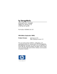
DIRECT-ATTACHED LIBRARY CONFIGURATION
In a direct-attached library configuration, the Windows or Solaris MediaAgents can be configured to use the StorageTek library controlled by ACSLS server: For
the Windows MediaAgent, you must install an instance of StorageTek’s Library attach for Windows program on the MediaAgent computer in which the
StorageTek library will be configured. (See Supported Software Versions for information on the supported versions.)
For the Sun Solaris MediaAgent, the ACSLS Client Service must be installed on the MediaAgent computer. This software is available in the Software Installation
Discs and can be installed during the MediaAgent installation. (See Install ACSLS Client Service on Solaris for more information on installing this software.)
The ACSLS server is connected to the library’s media changer with a direct SCSI. Each MediaAgent communicates with the ACSLS server through the TCP-IP
port. In addition, each MediaAgent must also be attached to the drive(s) in the library using SCSI ports.
Within the StorageTek libraries, some or all drives must be assigned to the MediaAgents for exclusive use by the
CommCell® group. The unassigned drives will be available for other applications or another CommCell® group.
Page 25 of 29
Pre-Installation Checklist
The following diagrams provide an overview of the hardware configuration required for configuring the StorageTek library using the ACSLS Server:
DIRECT-ATTACHED LIBRARY CONFIGURATION WITH SN6000
The ACSLS server is connected to the library’s media changer with a direct SCSI. Each MediaAgent communicates with the SN6000 through the TCP-IP port. In
addition, each MediaAgent must also be attached to SN6000 using Fibre Channel cables. The SN6000 is connected to all the drives in the library through
Bridge/Router using Fibre Channel cables.
The following diagram provides an overview of the hardware configuration required for configuring the StorageTek library using the ACSLS Server in the system
with StorageTek SN6000:
DDS CONFIGURATION
In a DDS configuration, all MediaAgents can be configured provided you have at least one of the Windows or Solaris MediaAgent. (See Supported Software
Versions for information on the supported versions.)
This primary MediaAgent must have the following software:
z
If the primary MediaAgent is a Windows MediaAgent, you must install an instance of StorageTek's Library attach for Windows program on the MediaAgent
computer.
z
If the primary MediaAgent is a Sun Solaris MediaAgent, the ACSLS Client Service must be installed on the MediaAgent computer. This software is available in
the Software Installation Discs and can be installed during the MediaAgent installation. (See Install ACSLS Client Service on Solaris for more information on
installing this software.)
The ACSLS server is connected to the library’s media changer with a direct SCSI. In addition, the primary MediaAgent must also be attached to the ACSLS
server through the TCP-IP port. Each MediaAgent in the CommCell® communicates with the drives in the library through the following:
z
MediaAgent to Bridge/ Router/ Gateway using SCSI ports.
Page 26 of 29
Pre-Installation Checklist
z
Bridge/ Router/ Gateway to a SAN switch using Fibre Channel cable.
z
SAN switch is connected to all the drives in the library using Fibre Channel cables.
The following diagram provides an overview of the hardware configuration required for sharing a StorageTek library among multiple MediaAgents with DDS
configuration.
DDS CONFIGURATION WITH SN6000
The ACSLS server is connected to the library's media changer with a direct SCSI. In addition, the primary MediaAgent must also be attached to the ACSLS
server and SN6000 through the TCP-IP port. Each MediaAgent in the CommCell® group communicates with the drives in the library through the following:
z
MediaAgent to Bridge/ Router/ Gateway using SCSI ports.
z
Bridge/ Router/ Gateway to SN6000 using Fibre Channel cable.
z
SN6000 to a SAN switch using Fibre Channel cable.
z
SAN switch is connected to all the drives in the library using Fibre Channel cables.
The following diagram provides an overview of the hardware configuration required for sharing a StorageTek library among multiple MediaAgents with DDS
configuration using SN6000.
Back to Top
Page 27 of 29
Pre-Installation Checklist
Hardware Configuration Guidelines - ADIC Libraries Attached to
Scalar Distributed Library Controller (SDLC)
TABLE OF CONTENTS
Software Requirements
Hardware Configuration
Direct-attached library configuration
DDS Configuration
SOFTWARE REQUIREMENTS
The following software versions are supported in the various components:
COMPONENT
SOFTWARE VERSION
MediaAgents - Windows
Windows 2000
Windows 2003 Server (32 bit)
Scalar Distributed Library Controller (SDLC)
DAS Client software
ADIC library
Windows 2008 Server
2.5
3.12
ADIC 1000 (or above)
The media changer should be attached to the computer in which the SDLC software is installed. Depending on your configuration some or all the drives may be
attached to this computer. If the library is shared among several MediaAgents, you must install the DAS Client software on all the MediaAgent computers in
which the library will be configured.
HARDWARE CONFIGURATION
Within a CommCell® group, depending on the environment, the MediaAgents can be configured to access the ADIC library controlled by a Scalar Distributed
Library Controller (SDLC) using one of the following configurations:
z
Direct-attached library configuration.
z
Dynamic Drive Sharing (DDS) configuration in the SAN environment.
DIRECT-ATTACHED LIBRARY CONFIGURATION
The SDLC is connected to the library’s media changer with a direct SCSI. Each MediaAgent communicates with SDLC through the TCP-IP port. In addition, each
MediaAgent must also be attached to the drive(s) in the library using SCSI ports.
Within the library, some or all drives must be assigned to the MediaAgents for exclusive use by the CommCell
group. The unassigned drives will be available for other applications or another CommCell group.
The following diagrams provide an overview of the hardware configuration required for configuring the ADIC library using SDLC:
Page 28 of 29
Pre-Installation Checklist
DDS CONFIGURATION
In a DDS configuration, the SDLC is connected to the library’s media changer with a direct SCSI. Each MediaAgent in the CommCell group communicates with
the SDLC and the drives in the library through the following:
z
MediaAgent to Bridge/ Router/ Gateway using SCSI ports
z
Bridge/ Router/ Gateway to a SAN switch using Fibre Channel cable.
z
SAN switch is connected to all the drives in the library using Fibre Channel cables.
The following diagram provides an overview of the hardware configuration required for sharing an ADIC library among multiple MediaAgents with DDS
configuration.
Back to Top
Page 29 of 29