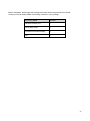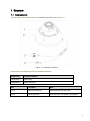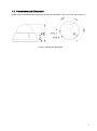
1
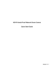
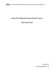
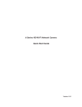
HD IR Vari-focal Dome Network Camera Quick Start Guide Model No. K-EF134L01E Version 1.0.0 Welcome Thank you for purchasing our Network camera! This user’s manual is designed to be a reference tool for your system. Please read the following safeguard and warnings carefully before you use this series product! Please keep this user’s manual well for future reference! Important Safeguards and Warnings 1.Electrical safety All installation and operation here should conform to your local electrical safety codes. Please check if the power supply is correct before operating the device. The power shall conform to the requirement in the SELV (Safety Extra Low Voltage) and the Limited power source is rated 12V DC, DC5V or AC24V in the IEC60950-1. (Power supply requirement is subject to the device label). Please install easy-to-use device for power off before installing wiring, which is for emergent power off when necessary. Please prevent the line cord from being trampled or pressed, especially the plug, power socket and the junction from the device. Note: Do not connect these two power supplying sources to the device at the same time; it may result in device damage! We assume no liability or responsibility for all the fires or electrical shock caused by improper handling or installation. We are not liable for any problems caused by unauthorized modification or attempted repair. 2.Environment Please don’t aim the device at strong light (such as lighting, sunlight and so on) to focus; otherwise it may cause overexposure (It is not the device malfunction), which will affect the longevity of CCD or CMOS. Please transport, use and store the device within the range of allowed humidity and temperature. Please don’t keep the device in a place which is wet, dusty, extremely hot, and extremely cold and with strong electromagnetic radiation or unstable lighting. Please do not allow water and other liquid falling into the camera in case that the internal components are damaged. Please do not allow rain or damp to the indoor device in case fire or lightning may occur. Please keep the sound ventilation in case of heat accumulation. Please pack the device with standard factory packaging or material with same quality when transporting the device. Heavy stress, violent vibration or water splash are not allowed during transportation, storage and installation. 3. Operation and Daily Maintenance Please do not touch the heat dissipation component of the device directly in order to avoid scald. i Please do not dismantle the device; there is no component which can be fixed by users themselves in the machine. It may cause water leakage or bad image for the device due to unprofessional dismantling. It is recommended to use the device with thunder proof device in order to improve thunder proof effect. The grounding holes of the product are recommended to be grounded to further enhance the reliability of the camera. Do not touch the CCD (CMOS) optic component directly. You can use the blower to clean the dust or dirt on the lens surface. Please use a dry cloth wetted by alcohol to wipe away the dust gently if it is necessary to clean. Always use the dry soft cloth to clean the device. If there is too much dust, please use the water to dilute the mild detergent first and then use it to clean the device. Finally use the dry cloth to clean the device. Don’t use volatile solvent like alcohol, benzene, thinner and etc or strong detergent with abrasiveness, otherwise it will damage the surface coating or reduce the working performance of the device. Dome cover is an optical device, please don’t touch or wipe cover surface directly during installation and use, please refer to the following methods to deal with once dirt is found: Stained with dirt Use oil-free soft brush or hair dries to remove it gently. Stained with grease or fingerprint Use soft cloth to wipe the water drop or oil gently to make it dry, then use oil-free cotton cloth or paper soaked with alcohol or detergent to wipe from the lens center to outward. It is ok to change the cloth and wipe several times if it is not clean enough. Warning Please use the standard accessories provided by manufacturer and make sure the device is installed and fixed by professional engineers. Please prevent the device surface from the radiation of laser beam when using laser beam device. Please do not provide two or more power supply modes for the device, otherwise it may cause damage to the device. Statement Please refer to the actual product for more details; the manual is just for reference. The manual will be regularly upgraded according to the product update; the upgraded content will be added in the manual without prior announcement. Please contact the supplier or customer service if there is any problem occurred when using the device. Please contact the customer service for the latest procedure and supplementary documentation. There may be deviation between the actual value of some data and the value provided in the manual due to the reasons such as the real environment is not stable and so on. Please refer to the company’s final explanation if there is any doubt or dispute. The company is not liable for any loss caused by the operation which is not followed by the manual. ii Before installation, please open the package and check all the components are included. Contact your local retailer ASAP if something is broken in your package. Accessory Name Amount Network Camera Unit 1 Quick Start Guide 1 Installation Accessories Bag 1 CD 1 iii Table of Contents 1 2 Structure ..................................................................................................................................... 1 1.1 Components .................................................................................................................. 1 1.2 Framework and Dimension ......................................................................................... 2 Device Installation ..................................................................................................................... 3 2.1 3 4 Installation Steps .......................................................................................................... 3 Quick Configuration Tool .............................................................................................. 5 3.1 Overview ........................................................................................................... 5 3.2 Operation .......................................................................................................... 5 Web Operation ............................................................................................................. 7 4.1 Network Connection .......................................................................................... 7 4.2 Login and Main Interface................................................................................... 7 iv 1 Structure 1.1 Components You can refer to the following figure for component structure. See Figure 1-1. Figure 1-1 Component structure Please refer to the following sheet for detailed information. Component Component Name Component 1 Dome body Component 2 Dome enclosure Port Port Name Note Port 3 Internet access port Network data in/out and PoE. Port 4 Power input port Connect to DC 12V power, input power. 1 1.2 Framework and Dimension Please refer to the following two figures for dimension information. The unit is mm. See Figure 1-2 Figure 1-2 Dimension illustration 2 2 Device Installation Important • Make sure that the installation area is strong enough to hold the product, such as a concrete ceiling. • Install the camera in the foundation area of the architecture or where sufficient strength is assured. • If a wall or ceiling board such as plasterboard is too weak to support the total weight, the area shall be sufficiently reinforced. Please see Figure 3-1 and Figure 3-2. 2.1 Installation Steps Figure 2-1 Please follow the steps listed below to install the device. Please refer to Figure 2-1 for reference. Step 1 Use inner hex wrench in the accessories bag to open dome enclosure by unfastening three inner hex screws on enclosure. Step 2 Please take the installation position map in the accessories bag, and then paste it on the ceiling or the wall according to your monitor area requirements and use a pen to mark the positions of the screws and cable mounting hole in the ceiling or wall. Note: If use pulls out cable from top of installation surface, you must dig an exit hole on installation surface according to the installation position map. 3 If user pulls out cable from side of cable channel, it must go through the U-shape channel on dome pedestal, and take out cable from the side exit hole on pedestal. Step3 Adjust the device installation pedestal to the proper position and then pull cable through the exit hole on Installation surface. Make direction of TOP sign same as it on installation position map. Remove the installation template label and attach the camera with 3 screws (locally procured). Fix dome body on installation surface. Step 4 Hold rotating bracket on both sides with hand, horizontally rotate bracket, adjusting lens horizontal direction to designated position. Loosen two hand screws on both sides of fixed rotating bracket. (Loosen only, do not take it down), hold the camera module body with hand, making lens rotate vertically. Adjust vertical direction of lens to appropriate angle, and fasten the M2 screw. Range of lens: vertical (0°~+75°), horizontal (0°~+355°). See Figure 2-2. Then, please adjust the viewing angle and focus. Notes: ・Viewing angle and focus adjustments shall be performed together with camera angle adjustment. ・Refer to the operation manual (included in the CD-ROM) for how to perform the zoom and focus settings from system menu. Figure 2-2 Step 5 Take dome enclosure, put it back on the camera properly regarding to screw and hole, and fasten the three inner hex screws with wrench. 4 3 Quick Configuration Tool 3.1 Overview Quick configuration tool can search current IP address, modify IP address. At the same time, you can use it to upgrade the device. Please note the tool only applies to the IP addresses in the same segment. 3.2 Operation Step 1 Double click the “ConfigTools.exe” icon; you can see an interface is shown as in Figure 3-. In the device list interface, you can view device IP address, port number, subnet mask, default gateway, MAC address and etc. Step 2 Select one IP address and then right click mouse, you can see an interface is shown as in Figure 3-1. Select the “Open Device Web” item; you can go to the corresponding web login interface. Figure 3-1 Search interface Figure 3-1 Search interface 2 5 Step 3 If you want to modify the device IP address without logging in the device web interface, you can go to the configuration tool main interface to set. In the configuration tool search interface (Figure 3-), please select a device IP address and then double click it to open the login interface. Or you can select an IP address and then click the Login button to go to the login interface. See Figure 3-3. In Figure 3-3, you can view device IP address, user name, password and port. Please modify the corresponding information to login. Please note the port information here shall be identical with the port value you set in TCP port in Web Network interface. Otherwise, you cannot login the device. If you are using device background upgrade port 3800 to login, other setups are all invalid. After you logged in, the configuration tool main interface is shown as below. See Figure 3-4. Figure 3-3 Login prompt Figure 3-4 Main interface For detailed information and operation instruction of the quick configuration tool, please refer to the Quick Configuration Tool User’s Manual included in the resources CD. 6 4 Web Operation This series network camera products support the Web access and management via PC. Web includes several modules: Monitor channel preview, system configuration, alarm and etc. 4.1 Network Connection Please follow the steps listed below for network connection. Make sure the network camera has connected to the network properly. Please set the IP address, subnet mask and gateway of the PC and the network camera respectively. Network camera default IP address is 192.168.0.10. Subnet mask is 255.255.255.0. Gateway is 192.168.0.1 Use order ping ***.***.***.***(* network camera address) to check connection is OK or not. 4.2 Login and Main Interface Open IE and input network camera address in the address bar. See Figure 4-1. Input your IP address here Figure 4-1 IP address The login interface is shown as below. See Figure 4-2. Please input your user name and password. Default factory name(ID) is admin and password(PWD) is 12345. Note: For security reasons, please modify your password after you first login. 7 Figure 4-2 Web login If it is your first time to log in, system pops up warning information to ask you whether install web plugin or not after you logged in for one minute. For detailed plug-in installation, please refer to the Web Operation Manual included in the resource CD. After you logged in, you can see the main window. Please refer to the Web Operation Manual included in the resource CD for detailed operation instruction. Note This quick start guide is for reference only. Slight difference may be found in user interface. All the designs and software here are subject to change without prior written notice. All trademarks and registered trademarks mentioned are the properties of their respective owners. If there is any uncertainty or controversy, please refer to the final explanation of us. 8