1
20-COMM-H RS-485 HVAC Adapter
Firmware Version 2.xxx
Modbus RTU
Metasys N2
Siemens Building Technologies P1 FLN
User Manual
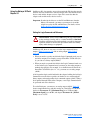
Important User Information
Solid state equipment has operational characteristics differing from those of
electromechanical equipment. Safety Guidelines for the Application,
Installation and Maintenance of Solid State Controls (Publication SGI-1.1
available from your local Rockwell Automation sales office or online at http://
www.rockwellautomation.com/literature) describes some important differences
between solid state equipment and hard-wired electromechanical devices.
Because of this difference, and also because of the wide variety of uses for solid
state equipment, all persons responsible for applying this equipment must
satisfy themselves that each intended application of this equipment is
acceptable.
In no event will Rockwell Automation, Inc. be responsible or liable for indirect
or consequential damages resulting from the use or application of this
equipment.
The examples and diagrams in this manual are included solely for illustrative
purposes. Because of the many variables and requirements associated with any
particular installation, Rockwell Automation, Inc. cannot assume responsibility
or liability for actual use based on the examples and diagrams.
No patent liability is assumed by Rockwell Automation, Inc. with respect to use
of information, circuits, equipment, or software described in this manual.
Reproduction of the contents of this manual, in whole or in part, without
written permission of Rockwell Automation, Inc. is prohibited.
Throughout this manual, when necessary we use notes to make you aware of
safety considerations.
!
WARNING: Identifies information about practices or
circumstances that can cause an explosion in a hazardous
environment, which may lead to personal injury or death, property
damage, or economic loss.
Important: Identifies information that is critical for successful application and
understanding of the product.
!
ATTENTION: Identifies information about practices or
circumstances that can lead to personal injury or death, property
damage, or economic loss. Attentions help you identify a hazard,
avoid a hazard, and recognize the consequences.
Shock Hazard labels may be located on or inside the equipment
(e.g., drive or motor) to alert people that dangerous voltage may be
present.
Burn Hazard labels may be located on or inside the equipment
(e.g., drive or motor) to alert people that surfaces may be at
dangerous temperatures.
PowerFlex, SMC Flex, DriveExplorer, DriveExecutive, DPI, DriveTools SP, and SCANport are either trademarks or registered trademarks
of Rockwell Automation, Inc.
Metasys is a trademark of Johnson Controls, Inc.
Modbus is a trademark of Schneider Automation.
P1 FLN is a trademark of Siemens Building Technologies.
Windows and Microsoft are registered trademarks of Microsoft Corporation.
20-COMM-H RS-485 HVAC Adapter User Manual
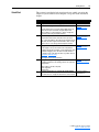
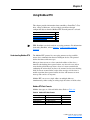
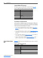
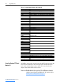
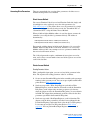
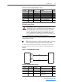
Summary of Changes
The information below summarizes the changes made to this manual since
its last release (March 2004):
Description of Changes
Reformatted document from half size (5.5 x 8.5 in.) to full size (8.5 x 11 in.)
Page
Throughout
manual
Added SMC Flex to the list of compatible products, and Metasys N2 is compatible with 1-2
PowerFlex 700VC drive.
Added new Adapter Modbus Register Map section.
4-2
Included information about using Modbus RTU mode to access 16-bit and 32-bit
4-10 and
parameters.
4-12
Added new Adapter Parameter Direct Access section.
4-13
Added new Metasys N2 Device Identity subsection.
5-1
Added new “Reference Setup Examples” subsection.
5-4
Added tip about configuring Analog Data Integers (ADIs).
5-9
Added Flashing Red/Green MOD status indicator information.
8-3
Added new Parameter 32 - [RTU Param Mode] to select the 16-bit default mode or
B-4
optional 32-bit mode in which the adapter operates.
20-COMM-H RS-485 HVAC Adapter User Manual
Publication 20COMM-UM009D-EN-P
soc-ii
Summary of Changes
20-COMM-H RS-485 HVAC Adapter User Manual
Publication 20COMM-UM009D-EN-P
Table of Contents
Preface
About This Manual
Related Documentation . . . . . . . . . . . . . . . . . . . . . . . . . . . . . . . . . . . . . . . . . . . . . . . . . . P-1
Rockwell Automation Support . . . . . . . . . . . . . . . . . . . . . . . . . . . . . . . . . . . . . . . . . . . . . P-2
Conventions Used in This Manual . . . . . . . . . . . . . . . . . . . . . . . . . . . . . . . . . . . . . . . . . . P-2
Chapter 1
Getting Started
Components. . . . . . . . . . . . . . . . . . . . . . . . . . . . . . . . . . . . . . . . . . . . . . . . . . . . . . . . . . . .
Features . . . . . . . . . . . . . . . . . . . . . . . . . . . . . . . . . . . . . . . . . . . . . . . . . . . . . . . . . . . . . . .
Compatible Products . . . . . . . . . . . . . . . . . . . . . . . . . . . . . . . . . . . . . . . . . . . . . . . . . . . . .
Required Equipment . . . . . . . . . . . . . . . . . . . . . . . . . . . . . . . . . . . . . . . . . . . . . . . . . . . . .
Safety Precautions . . . . . . . . . . . . . . . . . . . . . . . . . . . . . . . . . . . . . . . . . . . . . . . . . . . . . . .
Quick Start . . . . . . . . . . . . . . . . . . . . . . . . . . . . . . . . . . . . . . . . . . . . . . . . . . . . . . . . . . . .
Status Indicators . . . . . . . . . . . . . . . . . . . . . . . . . . . . . . . . . . . . . . . . . . . . . . . . . . . . . . . .
Chapter 2
Installing the Adapter
Preparing for an Installation . . . . . . . . . . . . . . . . . . . . . . . . . . . . . . . . . . . . . . . . . . . . . . .
Commissioning the Adapter . . . . . . . . . . . . . . . . . . . . . . . . . . . . . . . . . . . . . . . . . . . . . . .
Connecting the Adapter to the Drive. . . . . . . . . . . . . . . . . . . . . . . . . . . . . . . . . . . . . . . . .
Connecting the Adapter to the Network . . . . . . . . . . . . . . . . . . . . . . . . . . . . . . . . . . . . . .
Applying Power. . . . . . . . . . . . . . . . . . . . . . . . . . . . . . . . . . . . . . . . . . . . . . . . . . . . . . . . .
Chapter 3
1-1
1-2
1-2
1-3
1-3
1-5
1-6
2-1
2-1
2-3
2-6
2-7
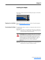
Configuring the Adapter
Configuration Tools. . . . . . . . . . . . . . . . . . . . . . . . . . . . . . . . . . . . . . . . . . . . . . . . . . . . . . 3-1
Using the PowerFlex 7-Class HIM . . . . . . . . . . . . . . . . . . . . . . . . . . . . . . . . . . . . . . . . . . 3-2
Setting the Node Address . . . . . . . . . . . . . . . . . . . . . . . . . . . . . . . . . . . . . . . . . . . . . . . . . 3-3
Setting the Network Data Rate . . . . . . . . . . . . . . . . . . . . . . . . . . . . . . . . . . . . . . . . . . . . . 3-3
Setting the Network Parity . . . . . . . . . . . . . . . . . . . . . . . . . . . . . . . . . . . . . . . . . . . . . . . . 3-4
Setting Stop Bits (Modbus RTU only) . . . . . . . . . . . . . . . . . . . . . . . . . . . . . . . . . . . . . . . 3-4
Setting the I/O Configuration . . . . . . . . . . . . . . . . . . . . . . . . . . . . . . . . . . . . . . . . . . . . . . 3-5
Setting a Network Time-out . . . . . . . . . . . . . . . . . . . . . . . . . . . . . . . . . . . . . . . . . . . . . . . 3-6
Setting a Fault Action . . . . . . . . . . . . . . . . . . . . . . . . . . . . . . . . . . . . . . . . . . . . . . . . . . . . 3-7
Resetting the Adapter . . . . . . . . . . . . . . . . . . . . . . . . . . . . . . . . . . . . . . . . . . . . . . . . . . . . 3-8
Viewing the Adapter Status Using Parameters . . . . . . . . . . . . . . . . . . . . . . . . . . . . . . . . . 3-9
Flash Updating the Adapter . . . . . . . . . . . . . . . . . . . . . . . . . . . . . . . . . . . . . . . . . . . . . . 3-10
Chapter 4
Using Modbus RTU
Understanding Modbus RTU . . . . . . . . . . . . . . . . . . . . . . . . . . . . . . . . . . . . . . . . . . . . . . 4-1
Adapter Modbus Register Map . . . . . . . . . . . . . . . . . . . . . . . . . . . . . . . . . . . . . . . . . . . . . 4-2
Using the Modbus RTU Point Map for I/O. . . . . . . . . . . . . . . . . . . . . . . . . . . . . . . . . . . . 4-4
Accessing Drive Parameters . . . . . . . . . . . . . . . . . . . . . . . . . . . . . . . . . . . . . . . . . . . . . . . 4-9
Using Broadcast Messages . . . . . . . . . . . . . . . . . . . . . . . . . . . . . . . . . . . . . . . . . . . . . . . 4-12
Adapter Parameter Direct Access . . . . . . . . . . . . . . . . . . . . . . . . . . . . . . . . . . . . . . . . . . 4-13
Chapter 5
Using Metasys N2
Understanding Metasys N2 . . . . . . . . . . . . . . . . . . . . . . . . . . . . . . . . . . . . . . . . . . . . . . . . 5-1
Using the Metasys N2 Point Map for I/O . . . . . . . . . . . . . . . . . . . . . . . . . . . . . . . . . . . . . 5-3
Using Metasys Configurable Objects to Access Parameters. . . . . . . . . . . . . . . . . . . . . . . 5-8
20-COMM-H RS-485 HVAC Adapter User Manual
Publication 20COMM-UM009D-EN-P
ii
Table of Contents
Chapter 6
Using Siemens Building Technologies P1 FLN
Understanding Siemens Building Technologies P1 FLN . . . . . . . . . . . . . . . . . . . . . . . . . 6-1
Using the P1 FLN Point Map for I/O . . . . . . . . . . . . . . . . . . . . . . . . . . . . . . . . . . . . . . . . 6-5
Using the P1 FLN Point Map to Access Parameters . . . . . . . . . . . . . . . . . . . . . . . . . . . . . 6-9
Chapter 7
Using Datalinks with All Protocols
Using Datalinks . . . . . . . . . . . . . . . . . . . . . . . . . . . . . . . . . . . . . . . . . . . . . . . . . . . . . . . . .
Using Datalinks with Modbus . . . . . . . . . . . . . . . . . . . . . . . . . . . . . . . . . . . . . . . . . . . . . .
Using Datalinks with Metasys N2 . . . . . . . . . . . . . . . . . . . . . . . . . . . . . . . . . . . . . . . . . . .
Using Datalinks with Siemens P1 FLN . . . . . . . . . . . . . . . . . . . . . . . . . . . . . . . . . . . . . . .
Chapter 8
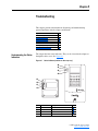
Troubleshooting
Understanding the Status Indicators . . . . . . . . . . . . . . . . . . . . . . . . . . . . . . . . . . . . . . . . .
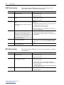
PORT Status Indicator . . . . . . . . . . . . . . . . . . . . . . . . . . . . . . . . . . . . . . . . . . . . . . . . . . . .
MOD Status Indicator . . . . . . . . . . . . . . . . . . . . . . . . . . . . . . . . . . . . . . . . . . . . . . . . . . . .
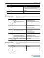
NET A Status Indicator . . . . . . . . . . . . . . . . . . . . . . . . . . . . . . . . . . . . . . . . . . . . . . . . . . .
NET B Status Indicator . . . . . . . . . . . . . . . . . . . . . . . . . . . . . . . . . . . . . . . . . . . . . . . . . . .
Viewing Adapter Diagnostic Items . . . . . . . . . . . . . . . . . . . . . . . . . . . . . . . . . . . . . . . . . .
Viewing and Clearing Events. . . . . . . . . . . . . . . . . . . . . . . . . . . . . . . . . . . . . . . . . . . . . . .
Appendix A
8-1
8-2
8-2
8-3
8-3
8-4
8-6
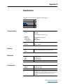
Specifications
Communications . . . . . . . . . . . . . . . . . . . . . . . . . . . . . . . . . . . . . . . . . . . . . . . . . . . . . . . .
Electrical . . . . . . . . . . . . . . . . . . . . . . . . . . . . . . . . . . . . . . . . . . . . . . . . . . . . . . . . . . . . . .
Mechanical. . . . . . . . . . . . . . . . . . . . . . . . . . . . . . . . . . . . . . . . . . . . . . . . . . . . . . . . . . . . .
Environmental . . . . . . . . . . . . . . . . . . . . . . . . . . . . . . . . . . . . . . . . . . . . . . . . . . . . . . . . . .
Regulatory Compliance . . . . . . . . . . . . . . . . . . . . . . . . . . . . . . . . . . . . . . . . . . . . . . . . . . .
Appendix B
7-1
7-3
7-4
7-5
A-1
A-1
A-1
A-1
A-2
Adapter Parameters
Parameter List . . . . . . . . . . . . . . . . . . . . . . . . . . . . . . . . . . . . . . . . . . . . . . . . . . . . . . . . . . B-1
Appendix C
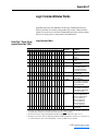
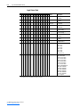
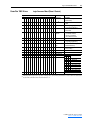
Logic Command/Status Words
PowerFlex 7-Class Drives (except PowerFlex 700S) . . . . . . . . . . . . . . . . . . . . . . . . . . . . C-1
PowerFlex 700S Drives . . . . . . . . . . . . . . . . . . . . . . . . . . . . . . . . . . . . . . . . . . . . . . . . . . . C-3
Glossary
Index
20-COMM-H RS-485 HVAC Adapter User Manual
Publication 20COMM-UM009D-EN-P
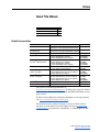
Preface
About This Manual
Topic
Related Documentation
Rockwell Automation Support
Conventions Used in This Manual
Page
P-1
P-2
P-2
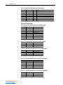
Related Documentation
For:
DriveExplorer™
Refer to:
http://www.ab.com/drives/driveexplorer, and
DriveExplorer online help (installed with the software)
DriveTools™ SP (includes
http://www.ab.com/drives/drivetools, and
DriveExecutive™)
DriveExecutive online help (installed with the software)
HIM
HIM Quick Reference
PowerFlex® 70/70EC Drive
PowerFlex 70 User Manual
PowerFlex 70/700 Reference Manual
PowerFlex 70EC/700VC Reference Manual
PowerFlex® 700/700VC Drive
PowerFlex 700 User Manual
PowerFlex® 700 Series B Drive
PowerFlex 700 Series B User Manual
PowerFlex 70/700 Reference Manual
PowerFlex 70EC/700VC Reference Manual
PowerFlex® 700H Drive
PowerFlex 700H Installation Instructions
PowerFlex 700H Programming Manual
PowerFlex® 700S Drive
PowerFlex 700S with Phase I Control User Manual
(Frames 1 through 6)
PowerFlex 700S with Phase II Control User Manual
PowerFlex 700S Reference Manual
PowerFlex® 700S Drive
PowerFlex 700S Installation Instructions
(Frames 9 and higher)
PowerFlex 700S with Phase I Control User Manual
PowerFlex 700S with Phase II Control User Manual
PowerFlex 700S Reference Manual
PowerFlex® 700L Drive
PowerFlex 700L User Manual
Modbus RTU Protocol Specification www.modicon.com/techpubs/TechPubNew
Publication
—
—
20HIM-QR001
20A-UM001
PFLEX-RM001
PFLEX-RM004
20B-UM001
20B-UM002
PFLEX-RM001
PFLEX-RM004
PFLEX-IN006
20C-PM001
20D-UM001
20D-UM006
PFLEX-RM002
PFLEX-IN006
20D-UM001
20D-UM006
PFLEX-RM002
20L-UM001
PI_MBUS_300.pdf
You can view or download publications at
www.literature.rockwellautomation.com. To order paper copies of technical
documentation, contact your local Rockwell Automation distributor or sales
representative.
To find your local Rockwell Automation distributor or sales representative,
visit www.rockwellautomation.com/locations.
For information such as firmware updates or answers to drive-related
questions, go to the Drives Service & Support web site at www.ab.com/
support/abdrives and click on the “Downloads” or “Knowledgebase” link.
20-COMM-H RS-485 HVAC Adapter User Manual
Publication 20COMM-UM009D-EN-P
P-2
About This Manual
Rockwell Automation
Support
Rockwell Automation, Inc. offers support services worldwide, with over 75
sales/support offices, over 500 authorized distributors, and over 250
authorized systems integrators located through the United States alone. In
addition, Rockwell Automation, Inc. representatives are in every major
country in the world.
Local Product Support
Contact your local Rockwell Automation, Inc. representative for:
•
•
•
•
Sales and order support
Product technical training
Warranty support
Support service agreements
Technical Product Assistance
For technical assistance, please review the information in Chapter 8,
Troubleshooting, first. If you still have problems, then access the
Allen-Bradley Technical Support web site at www.ab.com/support/abdrives
or contact Rockwell Automation, Inc.
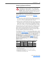
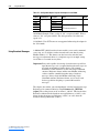
Conventions Used in This
Manual
The following conventions are used throughout this manual:
• Parameter names are shown in the format Parameter xx - [*]. The xx
represents the parameter number. The * represents the parameter name—
for example Parameter 01 - [DPI Port].
• Menu commands are shown in bold type face and follow the format
Menu > Command. For example, if you read “Select File > Open,” you
should click the File menu and then click the Open command.
• The firmware release is displayed as FRN X.xxx. The “FRN” signifies
Firmware Release Number. The “X” is the major release number. The
“xxx” is the minor update number.
• This manual provides information about the adapter and using it with
PowerFlex 7-Class (Architecture-Class) drives. The adapter can be used
with other products that support a DPI™ adapter, such as SMC™ Flex.
Refer to the documentation for your product for specific information
about how it works with the adapter.
20-COMM-H RS-485 HVAC Adapter User Manual
Publication 20COMM-UM009D-EN-P
Chapter 1
Getting Started
The adapter is a communication option intended for installation into a
PowerFlex 7-Class drive. It can also be used with other Allen-Bradley
products that support a DPI™ (Drive Peripheral Interface) adapter.
Topic
Components
Features
Compatible Products
Required Equipment
Safety Precautions
Quick Start
Status Indicators
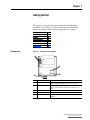
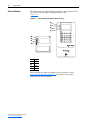
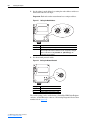
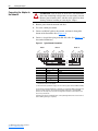
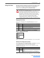
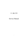
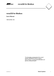
Components
Figure 1.1
Page
1-1
1-2
1-2
1-3
1-3
1-5
1-6
Components of the Adapter
➊
➍
➎
➌
Item
➊
Part
Status Indicators
➋
DPI Connector
➌
➍
➎
Terminal Block
Description
Four LEDs that indicate the status of the DPI, the adapter, and
network connection. Refer to Chapter 8, Troubleshooting.
A 20-pin, single-row shrouded male header. An Internal Interface
cable is connected to this connector and a connector on the
drive.
A 6-screw terminal block connects the adapter to the network.
Node Address Switches
Two switches set the node address.
Network Selector Switch
Switch selects the network protocol to which the adapter
operates.
20-COMM-H RS-485 HVAC Adapter User Manual
Publication 20COMM-UM009D-EN-P
1-2
Getting Started
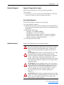
Features
The adapter features include:
• Typical mounting in a PowerFlex 7-Class drive using captive screws to
secure and ground the adapter to the drive.
• Compatibility with various configuration tools to configure the adapter
and connected drive. The tools include the PowerFlex HIM on the drive,
and drive-configuration software such as DriveExplorer (version 2.01 or
higher) or DriveExecutive (version 3.01 or higher).
• Status indicators that report the status of the drive communications, the
adapter, and network. They are visible when the drive cover is open or
closed.
• Parameter-configurable I/O (Logic Command/Reference and up to four
pairs of Datalinks) to meet application requirements.
• User-defined fault actions to determine how the adapter and PowerFlex
drive respond to communication disruptions on the network.
• Switches to allow setting a node address before applying power to the
drive. Alternatively, you can disable the switches and use a parameter to
configure the node address.
• A switch lets you select from the following three network protocols:
– Modbus™ RTU
– Metasys™ N2
– Siemens Building Technologies P1 FLN™
• Available read/write access to parameters, allowing parameter values to
be configured and monitored over the network.
• Support for DPI routing, enabling access to any networked PowerFlex
7-Class drive (with 20-COMM-H adapter) using DriveExplorer (version
2.01 or higher) to monitor and configure that drive and its connected
peripherals.
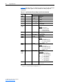
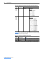
Compatible Products
DPI is a second generation peripheral communication interface. The adapter
is compatible with Allen-Bradley PowerFlex 7-Class drives and other
products that support DPI. At the time of publication, compatible products
include:
Network
Protocol
Modbus RTU
Metasys N2
Siemens P1 FLN
70
Compatible PowerFlex Drives
700EC 700VC 700H 700S
✔
7000
SMC
Flex
✔
✔
✔
✔
✔
✔
✔
✔
✔
✔
✔
✔
✔
✔
✔
✔
The PowerFlex 70/700 are used for examples in this manual. Refer to a DPI
Host product’s user manual for additional information.
20-COMM-H RS-485 HVAC Adapter User Manual
Publication 20COMM-UM009D-EN-P
Getting Started
Required Equipment
1-3
Equipment Shipped with the Adapter
When you unpack the adapter, verify that the package includes:
❑ One adapter
❑ A 2.54 cm (1 in.) and a 15.24 cm (6 in.) Internal Interface cable (only
one cable is needed to connect the adapter to the drive)
User-Supplied Equipment
To install and configure the adapter, you must supply:
❑ A small flathead screwdriver
❑ Network-specific cable to connect the adapter to the network. Refer to
the network-specific documentation for the cable recommendations and
requirements.
❑ Configuration tool, such as:
– PowerFlex 7-Class HIM (20-HIM-*)
– DriveExplorer (version 2.01 or higher)
– DriveExecutive stand-alone software (version 3.01 or higher) or
bundled with the DriveTools SP suite (version 1.01 or higher)
– Third-party network configuration software
❑ A PC connection to the network
Safety Precautions
Please read the following safety precautions carefully.
!
!
!
!
ATTENTION: Risk of injury or death exists. The PowerFlex
drive may contain high voltages that can cause injury or death.
Remove all power from the PowerFlex drive, and then verify
power has been discharged before installing or removing an
adapter.
ATTENTION: Risk of injury or equipment damage exists. Only
personnel familiar with drive and power products and the
associated machinery should plan or implement the installation,
start up, configuration, and subsequent maintenance of the
product using an adapter. Read and understand this entire manual
before proceeding. Failure to comply may result in injury and/or
equipment damage.
ATTENTION: Risk of equipment damage exists. The adapter
contains ESD (Electrostatic Discharge) sensitive parts that can be
damaged if you do not follow ESD control procedures. Static
control precautions are required when handling the adapter. If
you are unfamiliar with static control procedures, refer to
Guarding Against Electrostatic Damage (publication
8000-4.5.2).
ATTENTION: Risk of injury or equipment damage exists. If the
adapter is transmitting control I/O to the drive, the drive may fault
when you reset the adapter. Determine how your drive will
respond before resetting an adapter.
20-COMM-H RS-485 HVAC Adapter User Manual
Publication 20COMM-UM009D-EN-P
1-4
Getting Started
!
!
!
!
!
20-COMM-H RS-485 HVAC Adapter User Manual
Publication 20COMM-UM009D-EN-P
ATTENTION: Risk of injury or equipment damage exists.
Parameter 15 - [Comm Flt Action] lets you determine the
action of the adapter and connected drive if communications are
disrupted. By default, this parameter faults the drive. You can set
this parameter so that the drive continues to run. Precautions
should be taken to ensure that the setting of this parameter does
not create a risk of injury or equipment damage. When
commissioning the drive, verify that your system responds
correctly to various situations (for example, a disconnected
cable).
ATTENTION: Risk of injury or equipment damage exists.
Parameter 11 - [Network Timeout] lets you determine how
long it will take the adapter to detect network communication
losses. By default, this parameter sets the timeout to ten seconds.
It can be set so that the duration is shorter, longer, or disabled.
Take precautions to ensure that the setting does not create a risk
of injury or equipment damage. When commissioning the drive,
verify that your system responds correctly to various situations
(for example, a disconnected cable).
ATTENTION: Risk of injury or equipment damage exists. DPI
or SCANport host products must not be directly connected via
1202 cables. Unpredictable behavior due to timing and other
internal procedures can result if two or more hosts are connected
in this manner.
ATTENTION: Risk of injury or equipment damage exists.
When a system is configured for the first time, there may be
unintended or incorrect machine motion. Disconnect the motor
from the machine or process during initial system testing.
ATTENTION: Risk of injury or equipment damage exists. The
examples in this publication are intended solely for purposes of
example. There are many variables and requirements with any
application. Rockwell Automation, Inc. does not assume
responsibility or liability (to include intellectual property
liability) for actual use of the examples shown in this publication.
Getting Started
Quick Start
1-5
This section is provided to help experienced users quickly start using the
adapter. If you are unsure how to complete a step, refer to the referenced
chapter.
Step
1
2
3
Action
Review the safety precautions for the adapter.
Verify that the PowerFlex drive is properly installed.
Commission the adapter.
4
Select the network protocol using the adapter Network Selector
switch. Set a unique node address using the adapter Node
Address switches or set both switches to “0” and configure the
node address later using an adapter parameter.
Install the adapter.
5
6
Chapter 2,
Installing the Adapter
Verify that the PowerFlex drive and network are not powered.
Then, connect the adapter to the network using a network-specific
cable and to the drive using the Internal Interface cable. Use the
captive screws to secure and ground the adapter to the drive.
Apply power to the adapter.
Chapter 2,
Installing the Adapter
A. The adapter receives power from the drive. Verify that the
adapter and network are installed correctly and then turn on the
network and apply power to the drive. The status indicators
should be green. If they flash red, there is a problem. Refer to
Chapter 8, Troubleshooting.
B. Configure/verify key drive parameters.
Configure the adapter for your application.
Set adapter parameters for the following functions as required by
your application:
7
Refer to…
Throughout This Manual
Drive User Manual
Chapter 2,
Installing the Adapter
• Node address, data rate, and parity
• I/O configuration
• Fault actions
Set up the master device to communicate with the adapter.
Use a network tool to configure the master device on the network.
Chapter 3,
Configuring the Adapter
Instruction manual for
your network tool
20-COMM-H RS-485 HVAC Adapter User Manual
Publication 20COMM-UM009D-EN-P
1-6
Getting Started
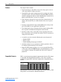
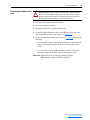
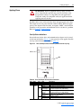
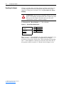
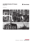
Status Indicators
The adapter uses four status indicators to report its operating status. They
can be viewed on the adapter or through the drive cover
(Figure 1.2).
Figure 1.2
Status Indicators (location on drive may vary)
➊
➋
➌
➍
➊
➋
➌
➍
Item Name
➊ PORT
➋
➌
➍
MOD
NET A
NET B
After installing the adapter and applying power to the drive, refer to
Start-Up Status Indications on page 2-7 for possible start-up status
indications and their descriptions.
20-COMM-H RS-485 HVAC Adapter User Manual
Publication 20COMM-UM009D-EN-P
Chapter 2
Installing the Adapter
This chapter provides instructions for installing the adapter in a PowerFlex
7-Class drive.
Topic
Preparing for an Installation
Commissioning the Adapter
Connecting the Adapter to the Drive
Connecting the Adapter to the Network
Applying Power
Page
2-1
2-1
2-3
2-6
2-7
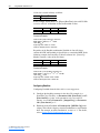
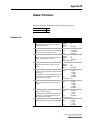
Preparing for an Installation Before installing the adapter, verify that you have all required equipment.
Refer to Required Equipment on page 1-3.
Commissioning the Adapter To commission the adapter, you must set a unique node address and select a
network protocol.
Important: New settings are recognized only when power is applied to the
adapter or it is reset. If you change a switch setting, cycle power
or reset the adapter to activate the changes.
!
ATTENTION: Risk of equipment damage exists. The adapter
contains ESD (Electrostatic Discharge) sensitive parts that can be
damaged if you do not follow ESD control procedures. Static
control precautions are required when handling the adapter. If
you are unfamiliar with static control procedures, refer to
Guarding Against Electrostatic Damage (publication
8000-4.5.2).
Important: To guard against device malfunction, it is recommended wear a
grounding wrist strap when installing the adapter.
20-COMM-H RS-485 HVAC Adapter User Manual
Publication 20COMM-UM009D-EN-P
2-2
Installing the Adapter
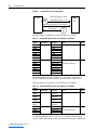
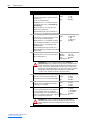
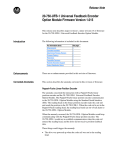
1. Set the adapter’s node address by rotating the node address switches to
the desired value for each digit.
Important: Each node on the network must have a unique address.
Figure 2.1
Setting the Node Address
2
2
3
4
1
0
5
9
6
7
8
Setting
01 – 99
00 (Default)
3
4
1
0
5
9
6
8
7
Description
Node address used by the adapter.
If network protocols are capable of handling a node address of 0 or node
addresses higher than 99, these addresses can be configured by setting the
switches to 00 and then setting Parameter 03 - [Net Addr Cfg] to the
desired network node address.
2. Set the network protocol switch.
Figure 2.2
Setting the Network Protocol
RTU
N2
P1
Setting
RTU (Default)
N2
P1
Description
Modbus RTU
Metasys N2
Siemens Building Technologies P1 FLN
The switch settings can be verified using a PowerFlex HIM, DriveExplorer
software, or DriveExecutive software, and viewing Diagnostic Device Item
numbers 40-42 (page 8-5).
20-COMM-H RS-485 HVAC Adapter User Manual
Publication 20COMM-UM009D-EN-P
Installing the Adapter
Connecting the Adapter to the
Drive
!
2-3
ATTENTION: Risk of injury or death exists. The PowerFlex
drive may contain high voltages that can cause injury or death.
Remove power from the drive, and then verify power has been
discharged before installing or removing the adapter.
1. Remove power from the drive and network.
2. Use static control precautions.
3. Remove the drive cover or open the drive door.
4. Connect the Internal Interface cable to the DPI port on the drive and
then to the DPI connector on the adapter (see Figure 2.3).
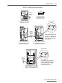
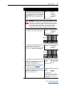
5. Secure and ground the adapter to the drive (see Figure 2.4) by doing the
following:
– On a PowerFlex 70 drive, fold the Internal Interface cable behind the
adapter and mount the adapter on the drive using the four captive
screws.
– On a PowerFlex 700, PowerFlex 700H or PowerFlex 700S drive,
mount the adapter on the drive using the four captive screws.
Important: Tighten all screws to properly ground the adapter.
Recommended torque is 0.9 N•m (8.0 lb•in).
20-COMM-H RS-485 HVAC Adapter User Manual
Publication 20COMM-UM009D-EN-P
2-4
Installing the Adapter
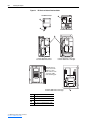
Figure 2.3
DPI Ports and Internal Interface Cables
20-COMM-H Adapter
➊
➋
➌
PowerFlex 70 - All Frames
➍
PowerFlex 700 Frames 0 and 1
PowerFlex 700S Frames 0 and 1
PowerFlex 700 Frames 2 and Larger
PowerFlex 700S Frames 2 through 6
HIM panel opens to
allow access to DPI
interface. To open
panel, remove screws
on left side of HIM
panel and swing open.
PowerFlex 700H Frames 9 and Larger
PowerFlex 700S Frames 9 and Larger
Item Description
➊ 15.24 cm (6 in.) Internal Interface cable
➋
➌
➍
20-COMM-H RS-485 HVAC Adapter User Manual
Publication 20COMM-UM009D-EN-P
DPI Connector
Ethernet cable
2.54 cm (1 in.) Internal Interface cable
X2
X1
➍
Installing the Adapter
Figure 2.4
2-5
Mounting and Grounding the Adapter
Drive
0.9 N•m
(8.0 lb•in)
4 Places
Adapter
Internal Interface Cable
folded behind the adapter
and in front of the drive.
Ground Tab Detail
PowerFlex 70 - All Frame Sizes
(Adapter mounts in drive.)
0.9 N•m
(8.0 lb•in)
4 Places
PowerFlex 700 Frames 0 and 1
PowerFlex 700S Frames 0 and 1
(Adapter mounts on door.)
Verify metal ground tab is bent 90°
and is under the adapter before
tightening screw. After tightening
the screw, verify continuity exists
between the head of the screw
and drive ground.
PowerFlex 700 Frames 2 and Larger
PowerFlex 700S Frames 2 through 6
(Adapter mounts in drive.)
Ground Tab Detail
X2
X1
0.9 N•m
(8.0 lb•in)
4 Places
PowerFlex 700H Frames 9 and Larger
PowerFlex 700S Frames 9 and Larger
(Adapter mounts behind HIM panel.)
Verify metal ground tab is bent 90° and
is under the adapter before tightening
screw. After tightening the screw, verify
continuity exists between the head of
the screw and drive ground.
20-COMM-H RS-485 HVAC Adapter User Manual
Publication 20COMM-UM009D-EN-P
2-6
Installing the Adapter
Connecting the Adapter to
the Network
ATTENTION: Risk of injury or death exists. The PowerFlex
drive may contain high voltages that can cause injury or death.
Remove power from the drive, and then verify power has been
discharged before installing or removing the adapter.
!
1. Remove power from the network and drive.
2. Use static control precautions.
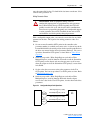
3. Connect an RS-485 cable to the network, and route it through the
bottom of the PowerFlex drive (Figure 2.4).
4. Connect a six-pin linear plug to the RS-485 cable. (See Figure 2.5 for
the terminal definitions.)
Typical Network Connections
Terminal
TERM
A
B
COM
SHIELD
GND
Signal
Termination (1)
Signal A
Signal B
Common
Shield
Ground (2)
O
M
SH
IE
G LD
N
D
C
B
Node "n"
TE
R
A M
O
M
SH
IE
G LD
N
D
C
TE
R
A M
Node 2
O
M
SH
IE
G LD
N
D
C
B
TE
R
A M
Node 1
B
Figure 2.5
Function
Signal RC Termination
TxRxDTxRxD+
Signal Common
Shield RC Termination
Shield GND Termination
(1)
Jumper terminals TERM and A on the adapter at end of the RS-485 network. This enables a built-in
RC termination network on the adapter.
(2)
The shield must be grounded at a single point on the network (jumper terminals SHIELD and GND).
A 3-wire network using Belden 3106A cable or equivalent is recommended for Modbus RTU applications
and shown in Figure 2.3 above. A 2-wire network using Belden 3105A cable or equivalent (COM
terminal is not connected) can also be used for most applications. However, a 3-wire network is more
robust in noisy environments.
For Metasys N2 or Siemens P1 FLN applications, refer to published guidelines from Johnson Controls or
Siemens Building Technologies respectively.
20-COMM-H RS-485 HVAC Adapter User Manual
Publication 20COMM-UM009D-EN-P
Installing the Adapter
Applying Power
2-7
ATTENTION: Risk of equipment damage, injury, or death
exists. Unpredictable operation may occur if you fail to verify
that parameter settings are compatible with your application.
Verify that settings are compatible with your application before
applying power to the drive.
!
Install the drive cover or close the drive door, and apply power to the drive.
The adapter receives its power from the connected drive. When you apply
power to the adapter for the first time, its topmost “PORT” status indicator
should be steady green after an initialization. If it is red, there is a problem.
Refer to Chapter 8, Troubleshooting.
Start-Up Status Indications
Status indicators for the drive and communications adapter can be viewed
on the front of the drive (Figure 2.6) after power has been applied. Possible
start-up status indications are shown in Table 2.A.
Figure 2.6
Drive and Adapter Status Indicators (location on drive may vary)
PORT
MOD
➋
NET A
NET B
➊
STS
Table 2.A Drive and Adapter Start-Up Status Indications
Item Name
Color
➊
Green
STS
(Status)
Yellow
Red
State
Description
Drive STS Indicator
Flashing
Drive ready but not running, and no faults are present.
Steady
Drive running, no faults are present.
Flashing,
An inhibit condition exists – the drive cannot be started.
Drive Stopped Check drive Parameter 214 - [Start Inhibits].
Flashing, Drive An intermittent type 1 alarm condition is occurring.
Running
Check drive Parameter 211 - [Drive Alarm 1].
Steady,
A continuous type 1 alarm condition exists. Check drive
Drive Running Parameter 211 - [Drive Alarm 1].
Flashing
A fault has occurred.
Steady
A non-resettable fault has occurred.
20-COMM-H RS-485 HVAC Adapter User Manual
Publication 20COMM-UM009D-EN-P
2-8
Installing the Adapter
Item Name
Color
➋
PORT
Green
MOD
Green
NET A
Green
NET B
Green
State
Description
Adapter Status Indicators
Flashing
Normal Operation. The adapter is establishing an I/O
connection to the drive. It will turn solid green or red.
Steady
Normal Operation. The adapter is properly connected
and communicating with the drive
Flashing
Normal Operation. The adapter is operating but is not
transferring I/O data.
Steady
Normal Operation. The adapter is operating and
transferring I/O data.
Flashing
Normal Operation. The adapter is properly connected
but does not have an I/O connection.
Steady
Normal Operation. The adapter is properly connected
and communicating on the network.
Off
Normal Operation. The adapter is properly connected
but is idle.
Flashing
Normal Operation. The adapter is properly connected
and transmitting data packets on the network.
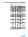
Configuring/Verifying Key Drive Parameters
The PowerFlex 7-Class drive can be separately configured for the control
and Reference functions in various combinations. For example, you could
set the drive to have its control come from a peripheral or terminal block
with the Reference coming from the network. Or you could set the drive to
have its control come from the network with the Reference coming from
another peripheral or terminal block. Or you could set the drive to have
both its control and Reference come from the network.
The following steps in this section assume that the drive will receive the
Logic Command and Reference from the network.
1. Use drive Parameter 090 - [Speed Ref A Sel] to set the drive speed
Reference to “22” (DPI Port 5).
2. If digital inputs are not used, change drive Parameters 361 - [Dig In1
Sel] through 366 - [Dig In6 Sel] to “0” (Not Used).
3. Verify that drive Parameter 213 - [Speed Ref Source] is reporting that
the source of the Reference to the drive is “22” (DPI Port 5). This
ensures that any Reference commanded from the network can be
monitored by using drive Parameter 002 - [Commanded Speed]. If a
problem occurs, this verification step provides the diagnostic capability
to determine whether the drive/adapter or the network is the cause.
20-COMM-H RS-485 HVAC Adapter User Manual
Publication 20COMM-UM009D-EN-P
Chapter 3
Configuring the Adapter
This chapter provides instructions and information for setting the
parameters in the adapter.
Topic
Configuration Tools
Using the PowerFlex 7-Class HIM
Setting the Node Address
Setting the Network Data Rate
Setting the Network Parity
Setting Stop Bits (Modbus RTU only)
Setting the I/O Configuration
Setting a Network Time-out
Setting a Fault Action
Resetting the Adapter
Viewing the Adapter Status Using Parameters
Flash Updating the Adapter
Page
3-1
3-2
3-3
3-3
3-4
3-4
3-5
3-6
3-7
3-8
3-9
3-10
For a list of parameters, refer to Appendix B, Adapter Parameters. For
definitions of terms in this chapter, refer to the Glossary.
Configuration Tools
The adapter stores parameters and other information in its own non-volatile
memory. You must, therefore, access the adapter to view and edit its
parameters. The following tools can be used to access the adapter
parameters:
Tool
PowerFlex HIM
DriveExplorer Software
(version 2.01 or higher)
DriveExecutive Software
(version 3.01 or higher)
Refer to…
page 3-2
http://www.ab.com/drives/driveexplorer, or
DriveExplorer online help (installed with the software)
http://www.ab.com/drives/drivetools, or
DriveExecutive online help (installed with the software)
20-COMM-H RS-485 HVAC Adapter User Manual
Publication 20COMM-UM009D-EN-P
3-2
Configuring the Adapter
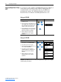
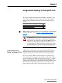
Using the PowerFlex 7-Class If your drive has either an LED or LCD HIM (Human Interface Module), it
can be used to access parameters in the adapter as shown below. It is
HIM
recommended that you read through the steps for your HIM before
performing the sequence. For additional information, refer to your
PowerFlex Drive User Manual or the HIM Quick Reference card.
Using an LED HIM
Step
1. Press ALT and then Sel (Device) to display
the Device Screen.
Key(s)
Example Screens
Device
ALT
2. Press the Up Arrow or Down Arrow to scroll
to the adapter. Letters represent files in the
drive, and numbers represent ports. The
adapter is usually connected to port 5.
Sel
or
3. Press the Enter key to enter your selection.
A parameter database is constructed, and
then the first parameter is displayed.
4. Edit the parameters using the same
techniques that you use to edit drive
parameters.
Using an LCD HIM
Step
1. In the main menu, press the Up Arrow or
Down Arrow to scroll to Device Select.
Key(s)
Example Screens
or
2. Press Enter to enter your selection.
3. Press the Up Arrow or Down Arrow to scroll
to the adapter (20-COMM-H).
4. Press Enter to select the adapter. A
parameter database is constructed, and
then the main menu for the adapter is
displayed.
5. Edit the parameters using the same
techniques that you use to edit drive
parameters.
or
F-> Stopped
Auto
0.00
Hz
Main Menu:
Diagnostics
Parameter
Device Select
Port 5 Device
20-COMM-H
Main Menu:
Diagnostics
Parameter
Device Select
NOTE: LCD HIM screens are shown throughout this chapter for example
configuration procedures.
20-COMM-H RS-485 HVAC Adapter User Manual
Publication 20COMM-UM009D-EN-P
Configuring the Adapter
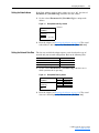
Setting the Node Address
3-3
If the Node Address switches on the adapter are set to “00,” the value of
Parameter 03 - [Net Addr Cfg] determines the node address.
1. Set the value of Parameter 03 - [Net Addr Cfg] to a unique node
address.
Figure 3.1
Example Net Addr Cfg 1 Screen
Default = 1
Port 5 Device
20-COMM-H
Parameter #: 03
Net Addr Cfg
1
0 <> 247
2. Reset the adapter (see Resetting the Adapter on page 3-8). The actual
node address is then displayed by Parameter 04 - [Net Addr Act].
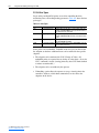
Setting the Network Data Rate
The data rate at which the adapter operates varies based on the type of
network and your network configuration. Refer to the following table.
Network
Modbus RTU
Metasys N2
Siemens Building Technologies P1 FLN
Possible Data Rates
4800, 9600, 19200, 38400
9600
4800, 9600
1. Set the value of Parameter 05 - [Net Rate Cfg] to the data rate at
which your network is operating.
Figure 3.2
Example Net Rate Cfg Screen
Port 5 Device
20-COMM-H
Parameter #: 05
Net Rate Cfg
1
9600
Value
0
1
2
3
Baud
4800
9600 (default)
19200
38400
2. Reset the adapter (see Resetting the Adapter on page 3-8). The actual
data rate is then displayed by Parameter 06 - [Net Rate Act].
20-COMM-H RS-485 HVAC Adapter User Manual
Publication 20COMM-UM009D-EN-P
3-4
Configuring the Adapter
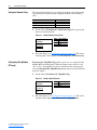
Setting the Network Parity
The parity that the adapter uses to verify data integrity varies based on the
type of network and your network configuration. Refer to the following
table.
Network
Modbus RTU
Metasys N2
Siemens Building Technologies P1 FLN
Possible Types of Parity
None, Even, or Odd
None
None
1. Set the value of Parameter 07 - [Net Parity Cfg] to the type of parity
that is used on the network.
Figure 3.3
Example Network Parity Screen
Port 5 Device
20-COMM-H
Parameter #: 07
Net Parity Cfg
0
None
Value
0
1
2
Type of Parity
None (default)
Odd
Even
2. Reset the adapter (see Resetting the Adapter on page 3-8). The actual
network parity is then displayed by Parameter 08 - [Net Parity Act].
Setting Stop Bits (Modbus
RTU only)
Parameter 30 - [Stop Bits Cfg] enables you to set 1 or 2 stop bits for the
Modbus RTU network protocol. When the adapter rotary switch is set to
“N2” or “P1,” the Stop Bits Cfg value is ignored and does not transfer to
read-only Parameter 09 - [Stop Bits Act] on power-up or reset (N2 and P1 are
fixed at 1 stop bit).
1. Set the value of Parameter 30 - [Stop Bits Cfg].
Figure 3.4
Example Stop Bits Screen
Port 5 Device
20-COMM-H
Parameter #: 30
Stop Bits Cfg
0
1-bit
Value
0
1
Type of Stop Bit
1-bit (default)
2-bits
2. Reset the adapter (see Resetting the Adapter on page 3-8). The actual
stop bits is then displayed by Parameter 09 - [Stop Bits Act].
20-COMM-H RS-485 HVAC Adapter User Manual
Publication 20COMM-UM009D-EN-P
Configuring the Adapter
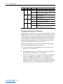
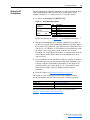
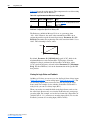
Setting the I/O
Configuration
3-5
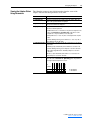
The I/O configuration determines the data that is sent to and from the drive.
Logic Command/Status, Reference/Feedback, and Datalinks may be
enabled or disabled. A “1” enables the I/O. A “0” disables the I/O.
1. Set the bits in Parameter 16 - [DPI I/O Cfg].
Figure 3.5
Example DPI I/O Cfg Screen
Port 5 Device
20-COMM-H
Parameter #: 16
DPI I/O Cfg
xxxxxxxxxxx0 0 0 0 1
Cmd/Ref
b00
Bit
0
1
2
3
4
5 - 15
Description
Logic Command/Reference (Default)
Datalink A
Datalink B
Datalink C (not used with Metasys N2
Datalink D (not used with Metasys N2
Not Used
Bit 0 is the right-most bit. In Figure 3.5, it is highlighted and equals “1.”
2. If Logic Command/Reference is enabled, configure the parameters in
the drive to accept the Logic Command and Reference from the adapter.
For example, set Parameter 90 - [Speed Ref A Sel] in a PowerFlex 70 or
700 drive to “22” (DPI Port 5) so that the drive uses the Reference from
the adapter. Also, verify that the mask parameters (for example,
Parameter 276 - [Logic Mask]) in the drive are configured to receive the
desired logic from the adapter. Refer to the documentation for your
drive for details.
3. If you enabled one or more Datalinks, configure parameters in the drive
to determine the source and destination of data in the Datalink(s). For
example, configure the Datalinks in PowerFlex 70 and 700 drives by
setting Parameters 300 - [Data In A1] to 317 - [Data Out D2]. Also,
ensure that this adapter is the only adapter using the enabled
Datalink(s).
4. Reset the adapter (see Resetting the Adapter on page 3-8).
The adapter is ready to send and receive I/O. The following chapters
provide information about basic data transfer for each type of protocol.
Network
Modbus RTU
Metasys N2
Siemens Building Technologies P1 FLN
Refer to…
Chapter 4, Using Modbus RTU
Chapter 5, Using Metasys N2
Chapter 6, Using Siemens Building Technologies P1 FLN
For details about using Datalinks for all types of networks, refer to
Chapter 7, Using Datalinks with All Protocols.
20-COMM-H RS-485 HVAC Adapter User Manual
Publication 20COMM-UM009D-EN-P
3-6
Configuring the Adapter
Setting a Network Time-out
The network timeout sets an interval within which the adapter must
communicate with its master. If this time is exceeded, the adapter
determines a loss of network communications has occurred and responds
with the action specified in Parameter 15 - [Comm Flt Action].
By default, the timeout is set to ten (10) seconds. You can increase or
decrease this value. Alternatively, you can set the value to zero (0) so that
the adapter does not detect communication losses.
!
ATTENTION: Risk of injury or equipment damage exists.
Parameter 11 - [Network Timeout] lets you determine how
long it will take your adapter to detect network communication
losses. By default, this parameter sets the timeout to ten (10)
seconds. You can set it so that the duration is shorter, longer, or
disabled. Take precautions to ensure that the setting does not
create a risk of injury or equipment damage. When
commissioning the drive, verify that your system responds
correctly to various situations (for example, a disconnected
cable).
Set the network timeout in Parameter 11 - [Network Timeout].
Figure 3.6
Example Network Timeout Screen
Port 5 Device
20-COMM-H
Parameter #: 11
Network Timeout
10
Sec
0 <> 180
Default = 10 seconds
Changes to this parameter take effect immediately. A reset is not required.
20-COMM-H RS-485 HVAC Adapter User Manual
Publication 20COMM-UM009D-EN-P
Configuring the Adapter
Setting a Fault Action
3-7
By default, when I/O communications are disrupted (for example, a cable is
disconnected), the drive responds by faulting if it is using I/O from the
network. You can configure a different response to disrupted I/O
communication using Parameter 15 - [Comm Flt Action].
ATTENTION: Risk of injury or equipment damage exists.
Parameter 15 - [Comm Flt Action] lets you determine the action
of the adapter and connected drive if I/O communications are
disrupted. By default, this parameter faults the drive. You can set
this parameter so that the drive continues to run. Precautions
should be taken to ensure that the setting of this parameter does
not create a risk of injury or equipment damage. When
commissioning the drive, verify that your system responds
correctly to various situations (for example, a disconnected cable).
!
Changing the Fault Action
Set the value of Parameter 15 - [Comm Flt Action] to the desired
response:
Value
0
1
2
Action
Fault
Stop
Zero Data
3
4
Hold Last
Send Flt Cfg
Figure 3.7
Description
The drive is faulted and stopped. (Default)
The drive is stopped, but not faulted.
The drive is sent 0 for output data. (The command word and Reference are
set to zero.) This does not command a stop.
The drive continues in its present state.
The drive is sent the data that you set in the fault configuration parameters
(Parameters 18 - [Flt Cfg Logic] through 27 - [Flt Cfg D2 In]).
Example Fault Action Screen
Port 5 Device
20-COMM-H
Parameter #: 15
Comm Flt Action
0
Fault
Changes to this parameter takes effect immediately. A reset is not required.
Setting the Fault Configuration Parameters
If you set Parameter 15 - [Comm Flt Action] to “Send Flt Cfg,” the values
in the following parameters are sent to the drive after an I/O
communications fault occurs. You must set these parameters to values
required by your application.
Parameter
25
26
27 – 34
Name
Flt Cfg Logic
Flt Cfg Ref
Flt Cfg x1 In
or
Flt Cfg x2 In
Description
A 16-bit value sent to the drive for Logic Command.
A 32-bit value (0 – 4294967295) sent to the drive as a Reference or
Datalink.
Important: If the drive uses a 16-bit Reference or 16-bit Datalinks, the most
significant word of the value must be set to zero (0) or a fault will occur.
Changes to these parameters take effect immediately. A reset is not required.
20-COMM-H RS-485 HVAC Adapter User Manual
Publication 20COMM-UM009D-EN-P
3-8
Configuring the Adapter
Resetting the Adapter
Changes to switch settings and some adapter parameters require that you
reset the adapter before the new settings take effect. You can reset the
adapter by cycling power to the drive or by using Parameter 14 - [Reset
Module].
!
ATTENTION: Risk of injury or equipment damage exists. If the
adapter is transmitting control I/O to the drive, the drive may fault
when you reset the adapter. Determine how your drive will
respond before resetting a connected adapter.
Set Parameter 14 - [Reset Module] to “1” (Reset Module).
Figure 3.8
Example Reset Module Screen
Port 5 Device
20-COMM-H
Parameter #: 14
Reset Module
1
Reset Module
Value
0
1
2
Description
Ready (Default)
Reset Module
Set Defaults
When you enter “1” (Reset Module), the adapter will be immediately reset.
When you enter “2” (Set Defaults), the adapter will set all adapter
parameters to their factory-default values. After performing a Set Defaults,
enter “1” (Reset Module) so that the new values take effect. The value of
this parameter will be restored to “0” (Ready) after the adapter is reset.
20-COMM-H RS-485 HVAC Adapter User Manual
Publication 20COMM-UM009D-EN-P
Configuring the Adapter
The following parameters provide information about the status of the
adapter. You can view these parameters at any time.
Parameter
04 - [Net Add Act]
06 - [Net Rate Act]
08 - [Net Parity Act]
09 - [Stop Bits Act]
Description
Displays the actual network address of the adapter.
Displays the network data rate actually used by the adapter. Only valid
values for the specified network are displayed.
Displays the actual network parity used by the adapter. Only valid values
for the specified network are displayed.
Displays the actual number of stop bits used by the selected protocol.
This value is network-dependent:
• ModBus RTU Protocol – The number of stop bits used depends on the
value set by Parameter 30 - [Stop Bits Cfg]). If the value is “0,” the
adapter uses 1 stop bit; otherwise, it uses 2 stop bits.
• Metasys N2 Protocol – Uses only 1 bit, so the adapter shows only this
value.
• Siemens Building Technologies P1 FLN Protocol – Uses only 1 bit, so
the adapter shows only this value.
10 - [Net Chksum Type] Displays the type of checksum used by the selected protocol. The values
are as follows:
• CRC16 (0) is Cyclic Redundancy Check with 0 as a seed value. The
Siemens Building Technologies P1 FLN protocol uses this checksum.
• RLC is Run Length Checksum. The Metasys N2 protocol uses this
checksum.
17 - [DPI I/O Act]
CRC16 (-1) is Cyclic Redundancy Check with -1 as a seed value. The
Modbus RTU protocol uses this checksum.
Displays the Reference/Feedback and Datalinks used by the adapter. This
value is the same as Parameter 16 - [DPI I/O Cfg] unless the parameter
was changed and the adapter was not reset.
Bit
Definition
Not Used
Not Used
Not Used
Datalink D
Datalink C
Datalink B
Datalink A
Cmd/Ref
Viewing the Adapter Status
Using Parameters
3-9
Default
Bit
x x x 0 0 0 0 1
7 6 5 4 3 2 1 0
0 = I/O disabled
1 = I/O enabled
20-COMM-H RS-485 HVAC Adapter User Manual
Publication 20COMM-UM009D-EN-P
3-10
Configuring the Adapter
Flash Updating the Adapter
The adapter can be flash updated over the network or serially through a
direct connection from a computer to the drive using a 1203-USB or
1203-SSS serial converter.
When flashing over the network, you can use the Allen-Bradley software
tool ControlFLASH, the built-in flash capability of DriveExplorer Lite or
Full, or the built-in flash capability of DriveExecutive.
When flashing through a direct serial connection from a computer to a
drive, you can use the same Allen-Bradley software tools described above,
or you can use HyperTerminal set to the X-modem protocol.
To obtain a flash update for this adapter, go to http://www.ab.com/support/
abdrives/webupdate. This site contains all firmware update files and
associated Release Notes that describe firmware update enhancements/
anomalies, how to determine the existing firmware version, and how to flash
update using DriveExplorer, DriveExecutive, ControlFLASH or
HyperTerminal.
20-COMM-H RS-485 HVAC Adapter User Manual
Publication 20COMM-UM009D-EN-P
Chapter 4
Using Modbus RTU
This chapter provides information about controlling a PowerFlex 7-Class
drive, setting its Reference, and accessing its parameters through
configurable objects when the Modbus RTU network protocol is selected.
Topic
Understanding Modbus RTU
Using the Modbus RTU Point Map for I/O
Accessing Drive Parameters
Using Broadcast Messages
Page
4-1
4-4
4-9
4-12
TIP: Datalinks can also be used for accessing parameters. For information
about using Datalinks, refer to Chapter 7, Using Datalinks with All
Protocols.
Understanding Modbus RTU
The Modbus RTU protocol is a messaging structure used to establish
master-slave communication between intelligent devices. The protocol
defines the format of the messages.
Messages from a master to a slave contain the address of the slave, a
function code defining the requested action, any data to be sent, and an
error-checking field. Messages from a slave to a master contain fields
confirming the action taken, any data to be returned, and an error-checking
field. If an error occurred in the receipt of the message or if the slave is
unable to perform the requested action, the slave will construct an error
message and send it as its response.
Modbus RTU can access a single address or multiple addresses
simultaneously, either reading or writing single-bit values or 16-bit values.
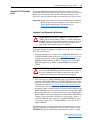
Modbus RTU Data Formats
Modbus data types are 1-bit and 16-bit values. Refer to Table 4.A.
Table 4.A Modbus RTU Data Formats
Modbus Type
Coil Status
Input Status
Holding Register
Input Register
Description
1-bit Discrete Output
1-bit Discrete Input
16-bit Output Register
16-bit Input Register
Reference
0x
1x
4x
3x
20-COMM-H RS-485 HVAC Adapter User Manual
Publication 20COMM-UM009D-EN-P
4-2
Using Modbus RTU
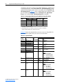
Supported Modbus RTU Commands
The adapter supports the Modbus RTU commands listed in Table 4.B.
Table 4.B Modbus RTU Commands Supported by RS-485 Adapter
Function Code
01
02
03
04
05
06
08
16
23
Description
Read Coil Status
Read Input Status
Read Holding Registers
Read Input Registers
Force Single Coil
Write Single Register
Diagnostics
Subfunction 00 Only - Return Query Data (loop back)
Write Multiple Registers
Read/Write 4x Registers
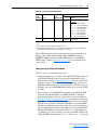
Data Addresses in Modbus Messages
All data addresses in Modbus messages are referenced to zero. That is, the
first occurrence of a data item is addressed as item number zero. Therefore,
when you create a message, you must address it to one less than the Modbus
address in the manual. The following are examples:
• Logic Command is Holding Register address 4x0001 in Table 4.F on
page 4-7, so you address it as register “0000” in the data address field of
the message.
• Feedback Hi is Input Register address 3x0003 in Table 4.H on page 4-8,
so you address it as register “0002” in the data address field of the
message.
• Start is Coil address 0x0002 in Table 4.E on page 4-6, so you address it
as coil “0001” in the data address field of the message.
• At Speed is Input address 1x0009 in Table 4.G on page 4-7, so you
address it as input “0008” in the data address field of the message.
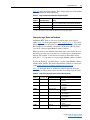
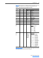
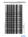
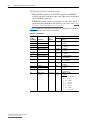
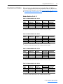
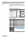
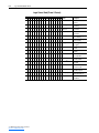
Adapter Modbus Register
Map
Table 4.C provides an overview of the Modbus register addresses and their
related functions.
Table 4.C Adapter Modbus Register Map
Modbus Register
0x0001
0x0002
0x0003
0x0004
0x0005
0x0006
0x0007
0x0008
20-COMM-H RS-485 HVAC Adapter User Manual
Publication 20COMM-UM009D-EN-P
Function
Write Product Command Word Bits
Stop
Start
Jog
Clear Faults
Direction
Local Control
MOP Increment
Using Modbus RTU
4-3
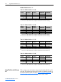
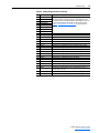
Table 4.C Adapter Modbus Register Map (Continued)
Modbus Register
0x0009
0x0010
0x0011
0x0012
0x0013
0x0014
0x0015
0x0016
1x0001
1x0002
1x0003
1x0004
1x0005
1x0006
1x0007
1x0008
1x0009
1x0010
1x0011
1x0012
1x0013
1x0014
1x0015
1x0016
3x0001
3x0002
3x0003
3x0004
3x0005
3x0006
3x0007
3x0008
3x0009
3x0010
3x0011
3x0012
3x0013
3x0014
3x0015
3x0016
3x0017
3x0018
3x0019
3x0020
3x0021
3x0022
3x0023
3x0024
3x0025
3x0026
3x0027
Function
Accel Rate
Decel Rate
Reference Select
MOP Decrement
Read Product Status Word Bits
Ready
Active
Command Direction
Actual Direction
Accel
Decel
Alarm
Fault
At Speed
Local Control
Reference
Read Various Input Registers
Product Status Word
Feedback Lo (Bits 0…15 of 32-bit Feedback)
Feedback Hi (Bits 16…31 of 32-bit Feedback or whole 16-bit Feedback)
Read USER IN 1
Read USER IN 2
Read USER IN 3
Read USER IN 4
Read USER IN 5
Read USER IN 6
Read USER IN 7
Read USER IN 8
Read Datalink A1 Out
Read Datalink A2 Out
Read Datalink B1 Out
Read Datalink B2 Out
Read Datalink C1 Out
Read Datalink C2 Out
Read Datalink D1 Out
Read Datalink D2 Out
20-COMM-H RS-485 HVAC Adapter User Manual
Publication 20COMM-UM009D-EN-P
4-4
Using Modbus RTU
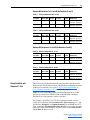
Table 4.C Adapter Modbus Register Map (Continued)
Modbus Register
4x0001
4x0002
4x0003
4x0004
4x0005
4x0006
4x0007
4x0008
4x0009
4x0010
4x0011
4x0012
4x0013
4x0014
4x0015
4x0016
4x0017
4x0018
4x0019
4x0020
4x0021
4x0022
4x0023
4x0024
4x0025
4x0026
4x0027
4x0028
4x0029
4x0030
4x0031
4x0032
4x0033
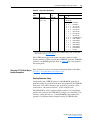
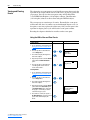
Using the Modbus RTU Point
Map for I/O
Function
Write Various Holding Registers
Product Logic Command
Reference Lo (Bits 0…15 of 32-bit Reference)
Reference Hi (Bits 16…31 of 32-bit Reference or whole 16-bit Reference)
Parameter # for USER IN1
Parameter # for USER IN2
Parameter # for USER IN3
Parameter # for USER IN4
Parameter # for USER IN5
Parameter # for USER IN6
Parameter # for USER IN7
Parameter # for USER IN8
Write USER OUT1
Write USER OUT2
Write USER OUT3
Parameter # for USER OUT1
Parameter # for USER OUT2
Parameter # for USER OUT3
Write Datalink A1 In
Write Datalink A2 In
Write Datalink B1 In
Write Datalink B2 In
Write Datalink C1 In
Write Datalink C2 In
Write Datalink D1 In
Write Datalink D2 In
4x0100 + param #
4x0100 + (param # x 2)
Direct Parameter Access
20-COMM-H Parameter Direct Access (with adapter in 16-bit mode)
20-COMM-H Parameter Direct Access (with adapter in 32-bit mode)
4x1000 + param #
4x1000 + (param # x 2)
Drive Parameter Direct Access (with adapter in 16-bit mode)
Drive Parameter Direct Access (with adapter in 32-bit mode)
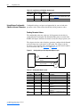
On Modbus, data transfers are used to transfer the I/O data that controls the
drive and sets its Reference. Note that output I/O is data that the master
device sends and the adapter receives. Input I/O is status data that the
adapter sends and the master device receives.
Important: In order for the drive to use the I/O and Reference from the
Modbus RTU network, you must set parameters in it and the
adapter to receive the I/O and Reference. For details, refer to
Setting the I/O Configuration on page 3-5.
20-COMM-H RS-485 HVAC Adapter User Manual
Publication 20COMM-UM009D-EN-P
Using Modbus RTU
4-5
Setting the Logic Command and Reference
!
ATTENTION: Select and use either the “Product Logic
Command Discrete Outputs (0x000x)” or the “Product Logic
Command Register Output (4x0001)” as a control method, but
not both. Conflicts caused from using both methods can result in
dangerous operation. Failure to observe this caution could cause
bodily injury and/or damage to equipment.
On Modbus RTU, there are two ways to set the logic command: discrete
outputs (Table 4.E on page 4-6) and register outputs (Table 4.F on
page 4-7).
• When you need to set only one bit in the logic command word, you can
use a discrete output. For example, to stop a PowerFlex 70/700 drive (bit
0), you can use a discrete output (Modbus Address 0x0001).
• When you need to set multi-bit fields in the logic status word or to set the
entire logic status word, you must use the register output to maintain data
integrity. For example, to set the direction of a PowerFlex 70/700 drive
(bits 4 and 5), you must use a register output (Modbus Address 4x0001).
A 16-bit product logic word is buffered in the adapter, holding the last logic
command sent to the drive regardless of whether it was sent through the
discrete outputs or through the product logic command register output.
When a bit is updated through the discrete outputs or the register output, a
new logic command is generated and sent to the drive.
To set the Reference, you must use a register output (Modbus Address 4x0002
and/or 4x0003 in Table 4.F on page 4-7). Remember that the Reference value
is a scaled value; it is not an engineering value. For example, in PowerFlex 70/
700 drives, the reference is scaled based on the value of Parameter 55 [Maximum Freq], but the commanded maximum speed can never exceed the
value of Parameter 82 - [Maximum Speed]. Table 4.D shows example
References and their results on a PowerFlex 70/700 drive that has its
Parameters 55 - [Maximum Freq] set to 130 Hz and 82 - [Maximum
Speed] set to 60 Hz.
Table 4.D Example Speed Reference and Feedback for a PowerFlex 70/700
Reference
Value
32767 (1)
16384
8192
0
(1)
(2)
(3)
Scale
Percent
100%
50%
25%
0%
Value
130 Hz
65 Hz
32.5 Hz
0 Hz
Output Speed
60 Hz (2)
60 Hz (2)
32.5 Hz
0 Hz
Feedback
Value
15123 (3)
15123 (3)
8192
0
A value of 32767 is equivalent to 100%. The effects of values greater than 32767 depend on
whether the DPI product uses a bipolar or unipolar direction mode. Refer to the
documentation for your DPI product.
The drive runs at 60 Hz instead of 130 Hz or 65 Hz because Parameter 82 - [Maximum
Speed] sets 60 Hz as the maximum speed.
The Feedback value is also scaled based on the value of Parameter 55 - [Maximum Freq],
For example, 60/130 = 0.46 so 32767 x 0.46 = 15123.
20-COMM-H RS-485 HVAC Adapter User Manual
Publication 20COMM-UM009D-EN-P
4-6
Using Modbus RTU
Table 4.E shows that there are 16 discrete points to represent the command
word bit by bit. These points can be used only for writing single-bit
commands.
Table 4.E Logic Command: Discrete Outputs (to Drive from Controller)
Modbus
Address
0x0001
0x0002
0x0003
0x0004
0x0005
0x0006
0x0007
0x0008
0x0009
0x0010
0x0011
0x0012
0x0013
0x0014
0x0015
0x0016
20-COMM-H RS-485 HVAC Adapter User Manual
Publication 20COMM-UM009D-EN-P
Logic Command PowerFlex 70/700 Example
Bit
Description
Values
0
Stop
0 = Not Stop
1 = Stop
1
Start (1) (2)
0 = Not Start
1 = Start
2
Jog
0 = Not Jog
1 = Jog
3
Clear Faults (2)
0 = Not Clear Faults
1 = Clear Faults
4
Direction
Modbus Address
5
06 05
0 0 = No Command
0 1 = Forward Command
1 0 = Reverse Command
1 1 = Hold Direction Control
6
Local Control
0 = No Local Control
1 = Local Control
7
MOP Increment
0 = Not Increment
1 = Increment
8
Accel Rate
Modbus Address
9
10 09
0 0 = No Command
0 1 = Accel Rate 1 Command
1 0 = Accel Rate 2 Command
1 1 = Hold Accel Rate
10
Decel Rate
Modbus Address
11
12 11
0 0 = No Command
0 1 = Decel Rate 1 Command
1 0 = Decel Rate 2 Command
1 1 = Hold Decel Rate
12
Reference Select
Modbus Address
13
15 14 13
14
0 0 0 = No Command
0 0 1 = Ref 1 (Ref A Select)
0 1 0 = Ref 2 (Ref B Select)
0 1 1 = Ref 3 (Preset 3)
1 0 0 = Ref 4 (Preset 4)
1 0 1 = Ref 5 (Preset 5)
1 1 0 = Ref 6 (Preset 6)
1 1 1 = Ref 7 (Preset 7)
15
MOP Decrement
0 = Not Decrement
1 = Decrement
(1)
A 0 = Not Stop condition (logic 0) must first be present before a 1 = Start condition will start the drive.
(2)
To perform this command, the value must change from “0” to “1.”
Using Modbus RTU
4-7
Table 4.F shows the register outputs. These outputs must be used for writing
multi-bit commands and the Reference.
Table 4.F Logic Command and Reference: Register Outputs
Modbus
Address
4x0001
Output Description
Product Logic Command
4x0002
Reference Lo
4x0003 (1) Reference Hi
(1)
Values
16-bit word. Bit definitions for PowerFlex 70/700 drives are in
Table 4.E. For other products, refer to their documentation.
Bit 0…15 of 32-bit reference.
Bit 16…31 of 32-bit reference or the whole 16-bit reference.
The reference value is sent only when accessing address 4x0003. If a 32-bit reference is used, the 32-bit value
will be merged together by register 4x0002 and 4x0003 when accessing address 4x0003.
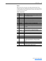
Viewing the Logic Status and Feedback
On Modbus RTU, there are two ways to view the logic status: discrete
inputs (Table 4.G) and register inputs (Table 4.H on page 4-8). You can use
discrete inputs when you need to view only one bit in the logic status word.
For example, to view whether a PowerFlex 70/700 drive is Ready (bit 0),
you can use a discrete input (Modbus Address 1x0001).
When you need to view multi-bit fields in the logic status word or to view
the entire logic status word, you must use a register input to maintain data
integrity. For example, to view the local control of a PowerFlex 70/700
drive (bits 9…11), you must use a register input (Modbus Address 3x0001).
To view the Feedback, you must also use a register input (Modbus Address
3x0002 and/or 3x0003). For details about how the feedback is scaled, refer
to the Setting the Logic Command and Reference on page 4-5.
Table 4.G shows that there are 16 discrete points to represent the status
word bit by bit. These points can be used only for reading single-bit status.
Table 4.G Logic Status: Discrete Inputs (to Controller from Drive)
Modbus
Address
1x0001
1x0002
1x0003
1x0004
1x0005
1x0006
1x0007
1x0008
1x0009
PowerFlex 70/700 Example
Logic Status Bit Description
Values
0
Ready
0 = Not Ready
1 = Ready
1
Active
0 = Not Running
1 = Running
2
Command Direction
0 = Reverse
1 = Forward
3
Actual Direction
0 = Reverse
1 = Forward
4
Accel
0 = Not Accelerating
1 = Accelerating
5
Decel
0 = Not Decelerating
1 = Decelerating
6
Alarm
0 = No Alarm
1 = Alarm
7
Fault
0 = No Fault
1 = Fault
8
At Speed
0 = Not At Reference
1 = At Reference
20-COMM-H RS-485 HVAC Adapter User Manual
Publication 20COMM-UM009D-EN-P
4-8
Using Modbus RTU
Table 4.G Logic Status: Discrete Inputs (to Controller from Drive) (Continued)
Modbus
Address
1x0010
1x0011
1x0012
1x0013
1x0014
1x0015
1x0016
PowerFlex 70/700 Example
Logic Status Bit Description
Values
9
Local Control
Modbus Address
10
12 11 10
11
0 0 0 = Port 0 (TB)
0 0 1 = Port 1
0 1 0 = Port 2
0 1 1 = Port 3
1 0 0 = Port 4
1 0 1 = Port 5
1 1 0 = Port 6
1 1 1 = No Local
12
Reference
Modbus Address
13
16 15 14 13
14
0 0 0 0 = Ref A Auto
15
0 0 0 1 = Ref B Auto
0 0 1 0 = Preset 2 Auto
0 0 1 1 = Preset 3 Auto
0 1 0 0 = Preset 4 Auto
0 1 0 1 = Preset 5 Auto
0 1 1 0 = Preset 6 Auto
0 1 1 1 = Preset 7 Auto
1 0 0 0 = Term Blk Manual
1 0 0 1 = DPI 1 Manual
1 0 1 0 = DPI 2 Manual
1 0 1 1 = DPI 3 Manual
1 1 0 0 = DPI 4 Manual
1 1 0 1 = DPI 5 Manual
1 1 1 0 = DPI 6 manual
1 1 1 1 = Jog Ref
Table 4.H shows the register inputs. These inputs must be used for reading
multi-bit status fields and the Feedback.
Table 4.H Logic Status and Feedback: Register Inputs
Modbus
Address
3x0001
Input Description
Product Status Word
3x0002
Feedback Lo
3x0003 (1) Feedback Hi
(1)
20-COMM-H RS-485 HVAC Adapter User Manual
Publication 20COMM-UM009D-EN-P
Values
16-bit word. Bit definitions for PowerFlex 70/700 drives are in
Table 4.G. For other products, refer to their documentation.
Bit 0…15 of 32-bit feedback
Bit 16…31 of 32-bit feedback or the whole 16-bit feedback.
The Feedback value is refreshed only when accessing address 3x0003. This is to maintain data integrity.
Using Modbus RTU
Accessing Drive Parameters
4-9
There are two methods for accessing drive parameters: the direct access
method and the pointer access method.
Direct Access Method
You can use Function Code 03 to read and Function Codes 06 (single) and
16 (multiple) to write, to directly access the drive parameters (see
Table 4.B on page 4-2). This allows direct access of parameters in a single
read or write as opposed to first having to write the “Param# for INx” or
“Param# for OUTx” using the Pointer Access Method.
When a 41000 or higher Modbus address is used, the adapter assumes the
controller is accessing the drive’s parameters directly. The address is
determined by:
16-bit Adapter Mode: Modbus Address = 41000 + (Drive Parameter #)
32-bit Adapter Mode: Modbus Address = 41000 + (Drive Parameter # x 2)
For example, with the adapter in 16-bit mode, Parameter 1 is accessed by
Modbus Address 41000. In the 32-bit mode, Parameter 1 is accessed by
Modbus Address 41002. Any attempts to access a parameter number that
does not exist will return an error.
The 32-bit adapter mode requires a minimum of two registers to read or
write, and is always an even number since two 16-bit registers are read for
each 32-bit data item.
Pointer Access Method
Reading Parameter Values
With a configurable input point, you can read any 16-bit parameter in the
drive. The sequence for reading parameter values is as follows:
1. Set one or more Param# for INx points in the controller to the parameter
number(s) that you want to read. You can set up to eight Param# for INx
points. Refer to Table 4.I on page 4-10.
2. Send a message with a Write Single Register (code 06) or Write
Multiple Register (code 16) function. You need to send the Param# for
INx point(s) to the adapter only one time per power cycle because,
when the adapter receives the Param# for INx point(s), it stores them in
its RAM. The adapter then continuously reads the values for the drive
parameters specified in the Param# for INx points.
3. Send a message with a Read Input Registers (code 04) function. The
adapter reads the drive parameter(s) that have been configured in the
Param# for IN point(s) and returns their values in the User INx point(s).
It can return up to eight User INx points. Refer to Table 4.I on
page 4-10. You can perform Read Input Registers continuously, if
desired.
20-COMM-H RS-485 HVAC Adapter User Manual
Publication 20COMM-UM009D-EN-P
4-10
Using Modbus RTU
Figure 4.1
Configurable Input Point Operations
Write Single Register (code 06)
or
Write Multiple Register (code 16)
Controller
Param#
for INx
Adapter
and
Drive
Read Input Registers (code 04) Request
Response Data
User
INx
With the adapter in 16-bit mode, 8 User IN items are available.
Table 4.I
Modbus
Address
3x0004
3x0005
3x0006
3x0007
3x0008
3x0009
3x0010
3x0011
4x0004
4x0005
4x0006
4x0007
4x0008
4x0009
4x0010
4x0011
Configurable Objects Inputs with Adapter in 16-bit Mode
Data Direction
Register Input
Description
User IN1
User IN2
User IN3
User IN4
User IN5
User IN6
User IN7
User IN8
Values
Depends on parameter selected
Register Output
Param # for IN1
Param # for IN2
Param # for IN3
Param # for IN4
Param # for IN5
Param # for IN6
Param # for IN7
Param # for IN8
0 = Not in use
- or 1 to maximum parameter #
User
Default
0
0
16-bit Mode Example: Write a value of “12” to register 4x0004. Read
register 3x0004 to read the 16-bit data value from drive parameter 12.
With the adapter in 32-bit mode, 4 User IN items are available.
Table 4.J Configurable Objects Inputs with Adapter in 16-bit Mode
Modbus
Address
3x0004
3x0005
3x0006
3x0007
3x0008
3x0009
3x0010
3x0011
4x0004
4x0005
4x0006
4x0007
Data Direction
Register Input
Description
User IN1 Lo
User IN1 Hi
User IN2 Lo
User IN2 Hi
User IN3 Lo
User IN3 Hi
User IN4 Lo
User IN4 Hi
Values
Depends on parameter selected
Register Output
Param # for IN1
Param # for IN2
Param # for IN3
Param # for IN4
0 = Not in use
- or 1 to maximum parameter #
User
Default
0
0
32-bit Mode Example: Write a value of “12” to register 4x0004. Read
register 3x0004 and store the returned 16-bit data. Read register 3x0005 and
20-COMM-H RS-485 HVAC Adapter User Manual
Publication 20COMM-UM009D-EN-P
Using Modbus RTU
4-11
store the returned 16-bit data. Use both 16-bit data items to make one 32-bit
value for drive parameter 12.
Writing Parameter Values
!
ATTENTION: Risk of equipment damage exists. If
configurable output points are programmed to write parameter
data to Non-Volatile Storage (NVS) frequently, the NVS will
quickly exceed its life cycle and cause the drive to malfunction.
Do not create a program that frequently uses configurable outputs
to write parameter data to NVS. Datalinks do not write to NVS
and should be used for frequently changed parameters.
With a configurable output point, you can write a new value for any 16-bit
parameter in the drive. The sequence for writing parameter values is as
follows:
1. Set one or more Param# for OUTx points in the controller to the
parameter number(s) to which you want to write. A value of zero in the
Param# field disables the writing of data for that specific point. Refer to
the drive user manual for the desired parameter number(s). You can set
up to three Param# for OUTx points at a time. Refer to Table 4.K on
page 4-12.
2. Send a message with a Write Single Register (code 06) or Write
Multiple Register (code 16) function. You need to send the Param# for
OUTx point(s) to the adapter only one time per power cycle because,
when the adapter receives the Param# for OUTx point(s), it stores them
in its RAM.
3. Set the values that you want to write to the parameters in the User
OUTx points. You can set up to three User OUTx points at a time. Refer
to Table 4.K on page 4-12.
4. Send a message with a Write Single Register (code 06) or Write
Multiple Register (code 16) function. Each time that the adapter
receives the values in the User OUTx points, it writes them to the drive
parameters.
Figure 4.2
Configurable Output Point Operations
Controller
Param#
for OUTx
User
OUTx
Write Single Register (code 06)
or
Write Multiple Register (code 16)
Adapter
and
Drive
Write Single Register (code 06)
or
Write Multiple Register (code 16)
20-COMM-H RS-485 HVAC Adapter User Manual
Publication 20COMM-UM009D-EN-P
4-12
Using Modbus RTU
Table 4.K Configurable Objects: Outputs with Adapter in 16-bit Mode
Modbus
Address
4x0012
4x0013
4x0014
4x0015
4x0016
4x0017
Data Direction
Register Output
Description
User OUT1
User OUT2
User OUT3
Param # for OUT1
Param # for OUT2
Param # for OUT3
Values
Depends on parameter selected
0 = Not in use
- or 1 to maximum parameter #
User
Default
0
0
16-bit Mode Example: Write a value of “101” to register 4x0015. Write a
value of “123” to register 4x0012. The drive parameter 101 value now
equals 12.3.
32-bit Mode: User OUT items are not supported when using the adapter in
the 32-bit mode.
Using Broadcast Messages
A Modbus RTU global broadcast feature enables you to send a command
(start, stop, etc.) to all drives on the network at the same time by using
Modbus Address “0.” This feature can also be used to write the same
message to each network drive via a single message, for example setting
Accel Time to 5 seconds in every drive.
Important: Every node capable of receiving a broadcast message will act
upon the message, so it is required that broadcast messages are
used only on networks of similar devices. For example,
PowerFlex 70 and 700 drives use the same Logic Command
structure, Reference format and the same Modbus addressing,
so these could be controlled together using a broadcast
message. Always check the Modbus addressing, Logic
Command structure, Reference format, etc. for every node
device type before designing a system with broadcast
messages.
The adapter also enables you to independently scale the broadcast message
Reference of its connected drive by using Parameter 31 - [RTU Ref.
Adjust]. The scaling factor can be set from 0…200.0%. This lets the drive
Reference either match the broadcast message Reference (= 100%), scale
below the broadcast message Reference (<100%), or scale above the
broadcast message Reference (>100%).
20-COMM-H RS-485 HVAC Adapter User Manual
Publication 20COMM-UM009D-EN-P
Using Modbus RTU
Adapter Parameter Direct
Access
4-13
Table 4.L provides an overview of the Modbus register addresses for
directly accessing the adapter parameters.
Table 4.L Adapter Parameter Direct Access Modbus Register Map
Modbus Register
4x0101
4x0102
4x0103
4x0104
4x0105
4x0106
4x0107
4x0108
4x0109
4x0110
4x0111
4x0112
4x0113
4x0114
4x0115
4x0116
4x0117
4x0118
4x0119
4x0120 (1)
4x0121
4x0122 (1)
4x0123
4x0124 (1)
4x0125
4x0126 (1)
4x0127
4x0128 (1)
4x0129
4x0130 (1)
4x0131
4x0132 (1)
4x0133
4x0134 (1)
4x0135
4x0136 (1)
4x0137
4x0138
4x0139 (1)
4x0140
4x0141
(1)
Parameter Description
DPI Port
DPI Data Rate
Net Addr Cfg
Net Addr Act
Net Rate Cfg
Net Rate Act
Net Parity Cfg
Net Parity Act
Stop Bits Act
Net Chksum Type
Network Timeout
Ref/Fdbk Size
Datalink Size
Reset Module
Comm Flt Action
DPI I/O Cfg
DPI I/O Act
Flt Cfg Logic
Flt Cfg Ref Lo
Flt Cfg Ref Hi
Flt Cfg A1 In Lo
Flt Cfg A1 In Hi
Flt Cfg A2 In Lo
Flt Cfg A2 In Hi
Flt Cfg B1 In Lo
Flt Cfg B1 In Hi
Flt Cfg B2 In Lo
Flt Cfg B2 In Hi
Flt Cfg C1 In Lo
Flt Cfg C1 In Hi
Flt Cfg C2 In Lo
Flt Cfg C2 In Hi
Flt Cfg D1 In Lo
Flt Cfg D1 In Hi
Flt Cfg D2 In Lo
Flt Cfg D2 In Hi
Clear Counters
N2 Ref Scale Lo
N2 Ref Scale Hi
Stop Bits Cfg
RTU Ref Adjust
A write access to this register triggers a store/update of this parameter value
to the internal adapter EEPROM as a 32-bit value.
20-COMM-H RS-485 HVAC Adapter User Manual
Publication 20COMM-UM009D-EN-P
4-14
Using Modbus RTU
Notes:
20-COMM-H RS-485 HVAC Adapter User Manual
Publication 20COMM-UM009D-EN-P
Chapter 5
Using Metasys N2
This chapter provides information about controlling a PowerFlex 7-Class
drive, setting its Reference, and accessing its parameters through
configurable objects when the Metasys N2 network protocol is selected.
Topic
Understanding Metasys N2
Using the Metasys N2 Point Map for I/O
Using Metasys Configurable Objects to Access Parameters
Page
5-1
5-3
5-8
TIP: Datalinks can also be used for accessing parameters. For information
about using Datalinks, refer to Chapter 7, Using Datalinks with All
Protocols.
Understanding Metasys N2
Metasys nodes are built up by the use of several virtual objects. The
Metasys N2 master performs read and write commands to these virtual
objects, and the adapter transfers/translates the data between these virtual
objects and the drive.
When a read or write command occurs to a certain dedicated virtual object,
data in the virtual objects is refreshed from or transferred to the drive.
The Metasys N2 master performs read and write commands to the virtual
objects one at a time. The data types that are used in the virtual objects are
binary input (BI), binary output (BO), analog input (AI), analog output
(AO), and internal integer (ADI), which is a 16-bit data value.
The Metasys master also performs cyclic polling of all the virtual objects.
Device Identity
The 20-COMM-H adapter must be configured in the master controller as a
Vendor device (VND) Code 10 hex.
Metasys N2 Virtual Objects
A Metasys N2 node may contain up to 256 virtual objects in each of its
seven different data types, called regions (Table 5.A).
20-COMM-H RS-485 HVAC Adapter User Manual
Publication 20COMM-UM009D-EN-P
5-2
Using Metasys N2
Table 5.A Description of the Regions of a Virtual Object
Region
Region 1
Region 2
Region 3
Region 4
Region 5
Region 6
Region 7
Type
Analog Input
Binary Input
Analog Output
Binary Output
Internal Float
Internal Integer
Internal Byte
Short
AI
BI
AO
BO
ADF
ADI
DB
Description
32-bit, IEEE-standard floats
1-bit
32-bit, IEEE-standard floats
1-bit
32-bit, IEEE-standard floats (Analog Data Float)
16-bit (Analog Data Integer)
8-bit (Analog Data Byte)
Metasys N2 Data Types
Table 5.B Internal Structure of Metasys N2 Analog Input (AI)
Attribute
1
2
3
8
9
10
11
12
Type
Byte
Byte
Float
Float
Float
Float
Float
Float
Description
Object Configuration
Object Status
Analog Input Value
Low Alarm Limit
Low Warning Limit
High Warning Limit
High Alarm Limit
Differential
Table 5.C Internal Structure of Metasys N2 Binary Input (BI)
Attribute
1
2
Type
Byte
Byte
Description
Object Configuration
Object Status
Table 5.D Internal Structure of Metasys N2 Analog Output (AO)
Attribute
1
2
3
Type
Byte
Byte
Float
Description
Object Configuration
Object Status
Current Value
Table 5.E Internal Structure of Metasys N2 Binary Output (BO)
Attribute
1
2
3
4
5
Type
Byte
Byte
Integer
Integer
Integer
Description
Object Configuration
Object Status
Minimum On-Time
Minimum Off-Time
Maximum Cycle/Hour
Table 5.F Internal Structure of Metasys N2 Internal Integer (ADI)
Attribute
1
2
20-COMM-H RS-485 HVAC Adapter User Manual
Publication 20COMM-UM009D-EN-P
Type
Byte
Integer
Description
Object Status
Current Value. Signed 16-bit.
Using Metasys N2
Using the Metasys N2 Point
Map for I/O
5-3
On Metasys N2, data transfers are used to transfer the I/O data that controls
the drive and sets its Reference. Note that Output I/O is data that the master
device sends and the adapter receives. Input I/O is status data that the
adapter sends and the master device receives.
Important: In order for the drive to use the I/O and Reference from the
Metasys N2 network, you must set parameters in it and the
adapter to receive the I/O and Reference. For details, refer to
Setting the I/O Configuration on page 3-5.
Setting the Logic Command and Reference
!
ATTENTION: Select and use either the point type Digital (BO)
or the word type Analog (AO) as a control method, but not both.
Conflicts caused from using both methods can result in dangerous
operation. Failure to observe this precaution could cause bodily
injury and/or damage to equipment.
On Metasys N2, there are two ways to set the logic command: binary
outputs (Table 5.L on page 5-5) and an analog output (Table 5.M on
page 5-6).
• When you need to set only one bit in the Logic Command word, you can
use binary outputs. For example, to stop a PowerFlex 70/700 drive (bit
0), you can use a binary output (BO#1).
• When you need to set multi-bit fields in the Logic Command word or to
set the entire Logic Command word, you must use the analog output to
maintain data integrity. For example, to set the Reference Selection of a
PowerFlex 70/700 drive (bits 12…14), you must use an analog output
(AO#1).
A 16-bit product logic word is buffered in the adapter, holding the last Logic
Command sent to the drive regardless of whether it was sent through the
binary outputs or through product logic command outputs (AO#1). When a
bit is updated through either of these outputs, a new Logic Command will
be generated and sent to the drive.
To set the Reference, you must use an analog output (AO#2). Table 5.G
shows example References and their results on a PowerFlex 70/700 drive
that has its Parameters 55 - [Maximum Freq] set to 70 Hz and 82 [Maximum Speed] set to 60 Hz, and adapter Parameter 29 - [N2 Ref
Scale] is set to 32,767.
20-COMM-H RS-485 HVAC Adapter User Manual
Publication 20COMM-UM009D-EN-P
5-4
Using Metasys N2
Table 5.G Example Speed Reference and Feedback for a PowerFlex 70/700 Drive
Reference (1)
Percent
100%
50%
25%
0%
Speed
70 Hz
35 Hz
17.5 Hz
0 Hz
Feedback (2)
Speed
60 Hz (3)
35 Hz
17.5 Hz
0 Hz
Percent
85.7%
50%
25%
0%
(1)
The actual value transmitted over the network is an engineering unit where
100% equals sending the value in the adapter Parameter 29 - [N2 Ref Scale],
and 0% equals sending a zero.
(2)
The Feedback percent value is also scaled based on the value of adapter
Parameter 29 - [N2 Ref Scale].
(3)
The drive runs at 60 Hz instead of 70 Hz because Parameter 82 - [Maximum
Speed] sets 60 Hz as the maximum speed.
Reference Setup Examples
Table 5.H PowerFlex 70EC and PowerFlex 700VC Default Example
Drive Parameters
Number
55 - [Maximum Freq]
82 - [Maximum Speed]
298 - [DPI Ref Sel]
(1)
20-COMM-H Parameter
Number
Value (1)
29 - [N2 Ref Scale]
15123
This value is calculated as follows: 60 ÷ 130 x 32767 = 15123.
Table 5.I
Maximum Freq = 70 Hz Example
Drive Parameters
Number
55 - [Maximum Freq]
82 - [Maximum Speed]
298 - [DPI Ref Sel]
(1)
Value
130
60
0 (Max Freq)
Value
70
60
0 (Max Freq)
20-COMM-H Parameter
Number
Value (1)
29 - [N2 Ref Scale]
28086
This value is calculated as follows: 60 ÷ 70 x 32767 = 28086.
Table 5.J Maximum Speed = 80 Hz Example
Drive Parameters
Number
55 - [Maximum Freq]
82 - [Maximum Speed]
298 - [DPI Ref Sel]
(1)
Value
130
80
0 (Max Freq)
20-COMM-H Parameter
Number
Value (1)
29 - [N2 Ref Scale]
20164
This value is calculated as follows: 80 ÷ 130 x 32767 = 20164.
Table 5.K DPI Reference Scaling = Max Speed Example
Drive Parameters
Number
55 - [Maximum Freq]
82 - [Maximum Speed]
298 - [DPI Ref Sel]
(1)
20-COMM-H RS-485 HVAC Adapter User Manual
Publication 20COMM-UM009D-EN-P
Value
130
60
1 (Max Speed)
20-COMM-H Parameter
Number
Value (1)
29 - [N2 Ref Scale]
32767
When drive parameter 298 - [DPI Ref Sel] = 1 (Max Speed), the Reference and Feedback scaling
is always defined as 32767, which will cause the drive to run at the value of drive parameter 82 [Maximum Speed]. In this example, the drive will run at 60 Hz.
Using Metasys N2
5-5
Table 5.L shows that there are 16 binary outputs to represent the command
word bit by bit. These outputs can be used only for writing single-bit
commands.
Table 5.L Logic Command: Binary Outputs (Inputs to a Drive)
PowerFlex 70/700 Example
Network Point Network Point Logic
Type (NPT)
Address (NPA) Command Bit Description Values
BO
1
0
Stop
0 = Not Stop
1 = Stop
BO
2
1
Start (1) (2)
0 = Not Start
1 = Start
BO
3
2
Jog
0 = Not Jog
1 = Jog
BO
4
3
Clear
0 = Not Clear Faults
Faults (2)
1 = Clear Faults
BO
5
4
Direction
Network Point Addresses
BO
6
5
06 05
0 0 = No Command
0 1 = Forward Command
1 0 = Reverse Command
1 1 = Hold Direction Control
BO
7
6
Local Control 0 = No Local Control
1 = Local Control
BO
8
7
MOP
0 = Not Increment
Increment
1 = Increment
BO
9
8
Accel Rate
Network Point Addresses
BO
10
9
10 09
0 0 = No Command
0 1 = Accel Rate 1
1 0 = Accel Rate 2
1 1 = Hold Accel Rate
BO
11
10
Decel Rate
Network Point Addresses
BO
12
11
12 11
0 0 = No Command
0 1 = Decel Rate 1
1 0 = Decel Rate 2
1 1 = Hold Decel Rate
BO
13
12
Reference
Network Point Addresses
Select
BO
14
13
15 14 13
BO
15
14
0 0 0 = No Command
0 0 1 = Ref 1 (Ref A Select)
0 1 0 = Ref 2 (Ref B Select)
0 1 1 = Ref 3 (Preset 3)
1 0 0 = Ref 4 (Preset 4)
1 0 1 = Ref 5 (Preset 5)
1 1 0 = Ref 6 (Preset 6)
1 1 1 = Ref 7 (Preset 7)
BO
16
15
MOP
0 = Not Decrement
Decrement
1 = Decrement
(1)
A 0 = Not Stop condition (logic 0) must first be present before a 1 = Start condition will start the drive.
(2)
To perform this command, the value must change from “0” to “1.”
20-COMM-H RS-485 HVAC Adapter User Manual
Publication 20COMM-UM009D-EN-P
5-6
Using Metasys N2
Table 5.M shows the analog outputs. These outputs must be used for writing
multi-bit commands and the Reference.
Table 5.M Logic Command and Reference: Analog Outputs
Network Point Network Point Parameter
Type (NPT)
Address (NPA) Description
AO
1
Product Logic
Command
AO
2
Reference
Range
16-bit word. Bit definitions for PowerFlex 70/700
drives are in Table 5.L. For other products, refer to
their documentation.
-100.0…100.0%
Additional Configuration Specific for Metasys N2
The Reference (AO#2) for Metasys N2 is set as a percentage from
-100…100%. However, the actual value transmitted over DPI is in an
engineering unit that equals the entered percentage. Parameter 29 - [N2
Ref Scale] determines the engineering unit value sent when AO#2 is set to
100%. The relationship is linear, where:
100%
0%
0
Pr. 29 Value
By default, Parameter 29 - [N2 Ref Scale] equals 32,767, which is the
maximum Reference value for PowerFlex 70/700 drives. Note that
additional scaling is performed in the PowerFlex 70/700 drive, where
32,767 equals the frequency selected in drive Parameter 55 - [Maximum
Freq]. For other DPI hosts, refer to the documentation of the specific DPI
host product.
Viewing the Logic Status and Feedback
On Metasys N2, there are two ways to view the Logic Status: binary inputs
(Table 5.N on page 5-7) and an analog input (Table 5.O on page 5-8). You
can use binary inputs when you need to view only one bit in the Logic
Status word. For example, to view whether a PowerFlex 70/700 drive is
ready (bit 0), you can use a binary input (BI 1).
When you need to view multi-bit fields in the Logic Status word, to view
the entire Logic Status word, or to view the Feedback word, you must use
an analog input. For example, to view the local control of a PowerFlex 70/
700 drive (bits 9…11), you must use an analog input (AI #1). To view the
Feedback, you must use an analog input (AI #2 or AI #3).
20-COMM-H RS-485 HVAC Adapter User Manual
Publication 20COMM-UM009D-EN-P
Using Metasys N2
5-7
Table 5.N shows that there are 16 binary inputs to represent the status word
bit by bit. These inputs can be used only for reading single-bit status.
Table 5.N Logic Status: Binary Inputs (Output from a Drive)
PowerFlex 70/700 Example
Network Point Network Point Logic
Type (NPT)
Address (NPA) Status Bit Description
Values
BI
1
0
Ready
0 = Not Ready
1 = Ready
BI
2
1
Active
0 = Not Running
1 = Running
BI
3
2
Command
0 = Reverse
Direction
1 = Forward
BI
4
3
Actual Direction 0 = Reverse
1 = Forward
BI
5
4
Accel
0 = Not Accelerating
1 = Accelerating
BI
6
5
Decel
0 = Not Decelerating
1 = Decelerating
BI
7
6
Alarm
0 = No Alarm
1 = Alarm
BI
8
7
Fault
0 = No Fault
1 = Fault
BI
9
8
At Speed
0 = Not At Reference
1 = At Reference
BI
10
9
Local Control
Network Point Addresses
BI
11
10
12 11 10
BI
12
11
0 0 0 = Port 0 (TB)
0 0 1 = Port 1
0 1 0 = Port 2
0 1 1 = Port 3
1 0 0 = Port 4
1 0 1 = Port 5
1 1 0 = Port 6
1 1 1 = No Local
Network Point Addresses
BI
13
12
Reference
(typically used 16 15 14 13
BI
14
13
when
BI
15
14
0 0 0 0 = Ref A Auto
commanding
BI
16
15
0 0 0 1 = Ref B Auto
drive speed
0 0 1 0 = Preset 2 Auto
from source
0 0 1 1 = Preset 3 Auto
other than
0 1 0 0 = Preset 4 Auto
Metasys)
0 1 0 1 = Preset 5 Auto
0 1 1 0 = Preset 6 Auto
0 1 1 1 = Preset 7 Auto
1 0 0 0 = Term Blk Manual
1 0 0 1 = DPI 1 Manual
1 0 1 0 = DPI 2 Manual
1 0 1 1 = DPI 3 Manual
1 1 0 0 = DPI 4 Manual
1 1 0 1 = DPI 5 Manual
1 1 1 0 = DPI 6 Manual
1 1 1 1 = Jog Ref
Table 5.O on page 5-8 shows the analog inputs. These inputs must be used
for reading multi-bit status fields and the Feedback.
20-COMM-H RS-485 HVAC Adapter User Manual
Publication 20COMM-UM009D-EN-P
5-8
Using Metasys N2
Table 5.O Logic Status and Feedback: Analog Inputs
Network Point Network Point Parameter
Type (NPT)
Address (NPA) Description
AI
1
Product Status
Word
AI
2
Feedback Lo
Range
16-bit word. Bit definitions for PowerFlex 70/700
drives are in Table 5.N. For other products, refer
to their documentation.
-100.0…100.0%
Configurable objects are inputs and outputs that let you read and write
Using Metasys Configurable
Objects to Access Parameters parameter values. These objects handle only 16-bit parameter values.
Reading Parameter Values
The configurable points may show any 16-bit parameter in the drive by
configuring the Param# point. The Param# for INx points are stored in the
RAM in the adapter and need to be written to only one time per power cycle.
The adapter reads the value of the drive parameter configured in the Param#
point and shows the result in the User INx point. The adapter reads the
parameter values from the drive continuously one at a time when Param# is
set to a non-zero value. See Figure 5.1 and Table 5.P.
Figure 5.1
Configurable Input Point Operation Objects Inputs
Controller
Drive
ADI
Param#
for INx
Request
Response Data
AI
User
INx
Table 5.P Configurable Objects: Inputs
20-COMM-H RS-485 HVAC Adapter User Manual
Publication 20COMM-UM009D-EN-P
Network Point
Type (NPT)
AI
AI
AI
AI
Network Point
Address (NPA)
3
4
5
6
ADI
1
ADI
2
ADI
3
ADI
4
Name
User IN1
User IN2
User IN3
User IN4
Description
User-defined Input 1
User-defined Input 2
User-defined Input 3
User-defined Input 4
Param # for IN1 0 (not in use), 1 to maximum # of drive
parameters
Param # for IN2 0 (not in use), 1 to maximum # of drive
parameters
Param # for IN3 0 (not in use), 1 to maximum # of drive
parameters
Param # for IN4 0 (not in use), 1 to maximum # of drive
parameters
Default
0
0
0
0
0
0
0
0
Using Metasys N2
5-9
Table 5.Q Example of Configurable Objects: Inputs
Network Point
Type (NPT)
AI
AI
AI
AI
Network Point
Address (NPA)
3
4
5
6
Name
Output Frequency
Output Current
Output Voltage
Output Power
Description
-400…400 Hz [0.1 Hz]
0.0 to Drive Related Amps [0.1 A]
0.0 to Drive Related Volts [0.1 VAC]
0.0 to Drive Related kW [0.1 kW]
Default
60.0
14.0
460.0
7.5
ADI
ADI
ADI
ADI
1
2
3
4
Param # for IN1
Param # for IN2
Param # for IN3
Param # for IN4
Integer # of drive parameter
Integer # of drive parameter
Integer # of drive parameter
Integer # of drive parameter
1
3
6
7
Writing Parameter Values
ATTENTION: Risk of equipment damage exists. If
configurable outputs are programmed to write parameter data to
Non-Volatile Storage (NVS) frequently, the NVS will quickly
exceed its life cycle and cause the drive to malfunction. Do not
create a program that frequently uses configurable outputs to
write parameter data to NVS. Datalinks do not write to NVS and
should be used for frequently changed parameters.
!
These outputs are written from the adapter each time the User OUT point is
written from the network.
TIP: Analog Data Integers (ADIs) are configured by first selecting
an Analog Output (AO) setpoint and then selecting the ADI.
A value of zero in the Param# field disables the writing of data for that
specific point. Refer to the drive user manual for the desired parameter
number.
Figure 5.2
Configurable Objects: Outputs
Controller
Drive
Param#
for OUTx
ADI
User
OUTx
AO
Table 5.R Configurable Objects: Outputs
Network Point
Type (NPT)
AO
AO
ADI
Network Point
Address (NPA)
3
4
5
ADI
6
Description
User OUT1
User OUT2
Param# for OUT1
Range
User-defined Output 1
User-defined Output 2
0 (not in use), 1 to maximum # of
drive parameters
Param# for OUT2 0 (not in use), 1 to maximum # of
drive parameters
Default
0
0
0
0
20-COMM-H RS-485 HVAC Adapter User Manual
Publication 20COMM-UM009D-EN-P
5-10
Using Metasys N2
Notes:
20-COMM-H RS-485 HVAC Adapter User Manual
Publication 20COMM-UM009D-EN-P
Chapter 6
Using Siemens Building Technologies P1 FLN
This chapter provides information about controlling a PowerFlex 7-Class
drive, setting its Reference, and accessing its parameters through points
when the Siemens Building Technologies P1 FLN network protocol is
selected.
Topic
Understanding Siemens Building Technologies P1 FLN
Using the P1 FLN Point Map for I/O
Using the P1 FLN Point Map to Access Parameters
Page
6-1
6-5
6-9
TIP: Datalinks can also be used for accessing parameters. For information
about using Datalinks, refer to Chapter 7, Using Datalinks with All
Protocols.
!
ATTENTION: Risk of injury or equipment damage exists. On
P1 FLN networks, 16-bit values are truncated to 15-bit values.
Unpredictable operation may result from using non-15-bit drive
parameters with the configurable points. Recognize the data
range limitation of P1 FLN and understand the data value ranges
of each parameter to be accessed over the network. Refer to the
drive user manual for information about drive parameter sizes.
P1 FLN nodes are built by the use of several points. The P1 FLN master
Understanding Siemens
Building Technologies P1 FLN controller performs read and write commands to these points, and the
adapter transfers/translates the data between these points and the drive.
All values (byte-sized, Boolean, and true integers) are represented in a
16-bit word over the network, where the sign bit is always positive. The
actual range allowed by P1 FLN, however, is always 15 bits: 0…32767 for
integers, 0…255 for bytes, and 0 or 1 for Boolean. The limit of 15 bits
prevents the use of the adapter’s P1 FLN mode with 32-bit DPI hosts, where
either Reference/Feedback or Datalink values are represented in 32-bit
format. 16-bit real values will be truncated to show only 15-bit values.
20-COMM-H RS-485 HVAC Adapter User Manual
Publication 20COMM-UM009D-EN-P
6-2
Using Siemens Building Technologies P1 FLN
P1 FLN Point Types
Logic analog and digital I/O points are used for controlling the drive,
monitoring status, and reading/writing parameters. Table 6.A shows the four
point types.
Table 6.A Point Types
Abbreviation Name
LDI
Logical Digital Inputs
LDO
LAI
LAO
Used for
Reading bit level points (0 or 1) such as drive status. For
example, FWD.REV MON (point 21) provides the status of
the rotation direction of the drive.
Logical Digital Outputs Writing bit-level points (0 or 1) such as drive commands. For
example, CMD RUN.STOP (Point 24) commands the drive
to run.
Logical Analog Inputs Reading word-level points such as FREQ OUTPUT (Point
03) and CURRENT (Point 06).
Logical Analog Outputs Writing word-level points such as REFERENCE (Point 92)
and acceleration (Point 31).
Some points can be unbundled. Unbundle means that you can characterize
the subpoint so that three additional items can be enabled for that specific
subpoint:
• The subpoint can be monitored for COV (Change of Value). All
unbundled points are reported for any change of value when a “Scan for
COV” command is issued. (Analog points may have COV limits defined
to reduce network traffic.)
• The subpoint can be overridden by the operator.
• Unbundling a point allows the operator to set up a virtual point in the
controller's database, which when commanded, can also affect the
subpoints in the device.
20-COMM-H RS-485 HVAC Adapter User Manual
Publication 20COMM-UM009D-EN-P
LAO
LAO
LAI
LAO
LAO
LAI
{32}
36
{37}
38
39
{44}
(4)
(3)
(2)
PARAM IN
USER IN
PARAM OUT
USER OUT
DLNK A1 OUT
DECEL TIME
READY
RUN ENABLE
DAY.NGT
CURRNT LIMIT
ACCEL TIME
Descriptor
CTRL ADDRESS
APPLICATION
FREQ OUTPUT
PCT OUTPUT
SPEED
CURRENT
TORQUE
POWER
DRIVE TEMP
DRIVE MWH
RUN TIME
DC BUS VOLT
OVRD TIME
FWD.REV MON
CMD FWD.REV
RUN.STOP MON
CMD RUN.STOP
1
1
1
1
1
0.1
1
1
1
0.1
0.1
English
Units
Slope
1
1
HZ
0.01
PCT
0.1
RPM
1
AMPS 0.1
PCT
0.1
KW
0.1
DEG C 0.1
MWH
0.1
HRS
0.1
VOLTS 0.1
1
1
1
1
1
0
0
0
0
0
0
0
0
0
0
0
Intercept
0
0
-163.83
0
0
0
-1638.3
0
-1638.3
0
0
0
0
0
0
0
0
0 – 32767
0 – 32767
0 – 32767
0 – 32767
0 – 32767
0 – 32767
0–1
0–1
0–1
0 – 255
0 – 32767
Range
0 – 255
0 – 32767
0 – 32767
0 – 32767
0 – 32767
0 – 32767
0 – 32767
0 – 32767
0 – 32767
0 – 32767
0 – 32767
0 – 32767
0 – 255
0–1
0–1
0–1
0–1
No
Yes
No
No
Yes
No
Yes
Yes
Yes
No
No
COV(4)
No
No
Yes
Yes
Yes
Yes
Yes
Yes
Yes
Yes
Yes
Yes
Yes
Yes
Yes
Yes
Yes
Description
Node address of this device.
Firmware application number.
Drive speed in frequency (Hertz).
Drive speed in percentage of max.
Drive speed in RPM.
Drive current consumption in amps.
Drive torque in percentage of max.
Drive power in kW.
Drive temperature in degree C.
Drive total power consumption in MWH.
Drive total run time in hours.
Drive DC bus voltage.
Not used by this application.
Monitor the rotation direction of the drive.
Command the rotation direction of the drive.
Monitor the Run/Stop status of the drive.
Command Run to the drive. A STOP issues a
momentary Stop command to the drive.
Monitor the Ready status of the drive.
Must be set to ENABLE to allow controlling the drive.
Not used by this application.
Current limit of the drive. Min value 0.9; max value 6.0
Acceleration time of the drive. Min value 0.1; max
value 3276.7
Deceleration time of the drive. Min value 0.1; max
value 3276.7
Parameter number to User In point.
User-defined input.
Parameter number to USER IN point.
User-defined output.
Bits 0-14 of Datalink Out A1.
COV indicates whether the points is able to support COVs and overrides.
Depends on DPI Host product connected to (PowerFlex 70, etc.) and HP size.
For a description of point types, refer to Table 6.A on page 6-2. Note that the outputs and inputs are from the network perspective, not the drive perspective. For example, an LAO is an output from the controller on
the network, but it is an input to the drive.
0
0
0
0
0
(3)
(3)
(3)
READY NOTRDY 0 (NOTRDY)
ENABLE STOP
0 (NO)
NIGHT DAY
0 (DAY)
ON Text OFF Text Default
99
2718
0
0
0
0
0
0
0
0
0
0
0
REV
FWD
0 (FWD)
REV
FWD
0 (FWD)
RUN
STOP
0 (STOP)
RUN
STOP
0 (NO)
Points not listed are not used in this application. Point numbers that appear in braces { } may be unbundled.
LDI
LDO
LDO
LAO
LAO
{25}
{26}
{29}
{30}
{31}
(1)
Point
Type(2)
LAO
LAO
LAI
LAI
LAI
LAI
LAI
LAI
LAI
LAI
LAI
LAI
LAO
LDI
LDO
LDI
LDO
Point
Number(1)
01
02
{03}
{04}
{05}
{06}
{07}
{08}
{09}
{11}
{12}
{13}
{20}
{21}
{22}
{23}
{24}
Table 6.B Siemens Building Technologies P1 FLN Point List
Using Siemens Building Technologies P1 FLN
6-3
Siemens Building Technologies P1 FLN Point Map
20-COMM-H RS-485 HVAC Adapter User Manual
Publication 20COMM-UM009D-EN-P
20-COMM-H RS-485 HVAC Adapter User Manual
Publication 20COMM-UM009D-EN-P
(3)
(2)
LOGIC STS LO
LOGIC STS HI
ERROR STATUS
Descriptor
DLNK A2 OUT
DLNK B1 OUT
DLNK B2 OUT
DLNK C1 OUT
DLNK C2 OUT
DLNK D1 OUT
DLNK D2 OUT
INPUT REF 1
INPUT REF 2
DLNK A1 IN
DLNK A2 IN
DLNK B1 IN
DLNK B2 IN
DLNK C1 IN
DLNK C2 IN
DLNK D1 IN
DLNK D2 IN
LOGIC CMD LO
LOGIC CMD HI
FEEDBACK
REFERENCE
OK.FAULT
RESET FAULT
1
1
1
English
Units
Slope
1
1
1
1
1
1
1
0.001
0.001
1
1
1
1
1
1
1
1
1
1
1
1
1
1
0
0
0
Intercept
0
0
0
0
0
0
0
-16.383
-16.383
0
0
0
0
0
0
0
0
0
0
0
0
0
0
0 – 255
0 – 255
0 – 255
Range
0 – 32767
0 – 32767
0 – 32767
0 – 32767
0 – 32767
0 – 32767
0 – 32767
0 – 32767
0 – 32767
0 – 32767
0 – 32767
0 – 32767
0 – 32767
0 – 32767
0 – 32767
0 – 32767
0 – 32767
0 – 255
0 – 255
0 – 32767
0 – 32767
0–1
0–1
Yes
Yes
Yes
COV(3)
Yes
Yes
Yes
Yes
Yes
Yes
Yes
Yes
Yes
Yes
Yes
Yes
Yes
Yes
Yes
Yes
Yes
Yes
Yes
Yes
Yes
Yes
Yes
Description
Bits 0-14 of Datalink Out A2.
Bits 0-14 of Datalink Out B1.
Bits 0-14 of Datalink Out B2.
Bits 0-14 of Datalink Out C1.
Bits 0-14 of Datalink Out C2.
Bits 0-14 of Datalink Out D1.
Bits 0-14 of Datalink Out D2.
Shows the Input Reference 1 parameter.
Shows the Input Reference 2 parameter.
Bits 0-14 of Datalink In A1.
Bits 0-14 of Datalink In A2
Bits 0-14 of Datalink In B1.
Bits 0-14 of Datalink In B2.
Bits 0-14 of Datalink In C1.
Bits 0-14 of Datalink In C2.
Bits 0-14 of Datalink In D1.
Bits 0-14 of Datalink In D2.
Lower 8 bits of Product Logic Command Word.
Higher 8 bits of Product Logic Command Word.
Feedback value bits 0-14 (absolute value).
Reference value bits 0-14.
Shows if the drive is faulted or not.
Resets the fault condition in the drive. Special point.
Will return to NORMAL (0) automatically.
Lower 8 bits of Product Logic Status Word.
Higher 8 bits of Product Logic Status Word.
Not used by this application.
COV indicates whether the points is able to support COVs and overrides.
For a description of point types, refer to Table 6.A on page 6-2. Note that the outputs and inputs are from the network perspective, not the drive perspective. For example, an LAO is an output from the controller on
the network, but it is an input to the drive.
0
0
0
ON Text OFF Text Default
0
0
0
0
0
0
0
0
0
0
0
0
0
0
0
0
0
0
0
0
0
FAULT OK
0 (OK)
RESET NORMAL 0 (NORMAL)
Points not listed are not used in this application. Point numbers that appear in braces { } may be unbundled.
LAI
LAI
LAO
{95}
{96}
{99}
(1)
Point
Type(2)
LAI
LAI
LAI
LAI
LAI
LAI
LAI
LAI
LAI
LAO
LAO
LAO
LAO
LAO
LAO
LAO
LAO
LAO
LAO
LAI
LAO
LDI
LDO
Point
Number(1)
{46}
{48}
{50}
{52}
{54}
{56}
{58}
{60}
{61}
{62}
{64}
{66}
{68}
{70}
{72}
{74}
{76}
{89}
{90}
{91}
{92}
{93}
{94}
Table 6.B Siemens Building Technologies P1 FLN Point List (Continued)
6-4
Using Siemens Building Technologies P1 FLN
Using Siemens Building Technologies P1 FLN
Using the P1 FLN Point Map
for I/O
6-5
On Siemens Building Technologies P1 FLN, data transfers are used to
transfer the I/O data that controls the drive and sets its Reference. Note that
Output I/O is data that the master device sends and the adapter receives.
Input I/O is status data that the adapter sends and the master device receives.
Important: In order for the drive to use the I/O and Reference from the P1
FLN network, you must set parameters in it and the adapter to
receive the I/O and Reference. For details, refer to
Setting the I/O Configuration on page 3-5.
Setting the Logic Command and Reference
!
ATTENTION: Select and use either the point type Digital
(LDO) or the word type Analog (LAO) as a control method, but
not both. Conflicts caused from using both methods can result in
dangerous operation. Failure to observe this precaution could
cause bodily injury and/or damage to equipment.
On Siemens Building Technologies P1 FLN, there are two ways to control a
drive and set its Reference.
• The more common way uses points such as CMD RUN.STOP (point 24)
and RUN ENABLE (point 26). Refer to Table 6.B on page 6-3 for a list
of points. For example, to start a PowerFlex 70/700 drive, you can set
CMD RUN.STOP (point 24) to “RUN.” To stop it, you can set CMD
RUN.STOP (point 24) to “STOP” or RUN ENABLE (point 26) to
“STOP.”
!
ATTENTION: LOGIC CMD LO (point 89) must be written
prior to LOGIC CMD HI (point 90) to maintain data integrity of
the Logic Command word. Failure to observe this precaution
could result in bodily injury and/or damage to equipment.
• The second way uses LOGIC CMD HI (point 90) and LOGIC CMD LO
(point 89). The LOGIC CMD LO and LOGIC CMD HI points are both
8-bit points. The adapter joins these two words together to make a 16-bit
command word. Refer to Appendix C, Logic Command/Status Words,
for definitions of the bits in the command word. The command word in
the adapter’s buffer is updated with the content of LOGIC CMD LO and
LOGIC CMD HI points. It is transferred to the drive when LOGIC CMD
HI is written. Therefore, to maintain data integrity of the command word,
LOGIC CMD LO must be written prior to writing LOGIC CMD HI. For
example, to start a PowerFlex 70/700 drive, you can write a value of “2”
to LOGIC CMD LO and a value of “0” to LOGIC CMD HI. To stop it,
you can write a value of “1” to LOGIC CMD LO and a value of “0” to
LOGIC CMD HI.
The Reference value is a 16-bit value in the drive but will only use 15 bits
due to the P1 FLN protocol limitation. You can send the reference using
REFERENCE (point 92). Remember that the Reference value is a scaled
20-COMM-H RS-485 HVAC Adapter User Manual
Publication 20COMM-UM009D-EN-P
6-6
Using Siemens Building Technologies P1 FLN
engineering value. For example, in PowerFlex 70/700 drives, the Reference
is scaled based on the value of Parameter 55 - [Maximum Freq], but the
commanded maximum speed can never exceed the value of Parameter 82 [Maximum Speed]. Table 6.C shows example References and their results
on a PowerFlex 70/700 drive that has its Parameters 55 - [Maximum
Freq] set to 130 Hz and 82 - [Maximum Speed] set to 60 Hz.
Table 6.C Example Speed Reference and Feedback for a PowerFlex 70/700
Reference
Value
32767
16384
8192
0
Scale
Percent
100%
50%
25%
0%
Value
130 Hz
65 Hz
32.5 Hz
0 Hz
Output Speed
60 Hz (1)
60 Hz (1)
32.5 Hz
0 Hz
Feedback
Value
15123 (2)
15123
8192
0
(1)
The drive runs at 60 Hz instead of 130 Hz because Parameter 82 - [Maximum Speed]
sets 60 Hz as the maximum speed.
(2)
The Feedback value is also scaled based on the value of Parameter 55 - [Maximum
Freq]. For example, 60/130 = 0.46 so 32767 x 0.46 = 15123.
Table 6.D shows the commands that you can execute on a PowerFlex 70/
700 drive and the point(s) that you can use to execute them.
Table 6.D Logic Commands
Point
Number(s)
24
26
89
24
89
89
20-COMM-H RS-485 HVAC Adapter User Manual
Publication 20COMM-UM009D-EN-P
PowerFlex 70/700 Example
Logic
Descriptio
Command Bit n
Values
0 = Not Stop
0
Stop (1)
1 = Stop (3)
Point
CMD RUN.STOP
RUN ENABLE
LOGIC CMD LO bit 0
CMD RUN.STOP
1
LOGIC CMD LO bit 0
LOGIC CMD LO bit 2 2
94
89
22
89
RESET FAULTS
3
LOGIC CMD LO bit 3
CMD FWD.REV
4 and 5
LOGIC CMD LO
bits 4, 5
89
LOGIC CMD LO bit 6 6
89
LOGIC CMD LO bit 7 7
90
LOGIC CMD HI
bits 0, 1
8 and 9
90
LOGIC CMD HI
bits 3, 2
10 and 11
Start (1) (2)
0 = Not Start
1 = Start
Jog
0 = Not Jog
1 = Jog
Clear
0 = Not Clear Faults
Faults(2)
1 = Clear Faults
Direction
Bits
05 04
0 0 = No Command
0 1 = Forward Command
1 0 = Reverse Command
1 1 = Hold Direction Control
Local
0 = No Local Control
Control
1 = Local Control
MOP
0 = Not Increment
Increment 1 = Increment
Accel Rate LOGIC CMD HI Bits
01 00
0 0 = No Command
0 1 = Accel Rate 1
1 0 = Accel Rate 2
1 1 = Hold Accel Rate
Decel Rate LOGIC CMD HI Bits
03 02
0 0 = No Command
0 1 = Decel Rate 1
1 0 = Decel Rate 2
1 1 = Hold Decel Rate
Using Siemens Building Technologies P1 FLN
6-7
Table 6.D Logic Commands (Continued)
Point
Logic
Number(s) Point
Command Bit
90
LOGIC CMD HI bits 12, 13, and 14
6, 5, 4
90
LOGIC CMD HI
bit 7
15
PowerFlex 70/700 Example
Descriptio
n
Values
Reference Bits
Select
06 05 04
0 0 0 = No Command
0 0 1 = Ref 1 (Ref A Select)
0 1 0 = Ref 2 (Ref B Select)
0 1 1 = Ref 3 (Preset 3)
1 0 0 = Ref 4 (Preset 4)
1 0 1 = Ref 5 (Preset 5)
1 1 0 = Ref 6 (Preset 6)
1 1 1 = Ref 7 (Preset 7)
MOP
0 = Not Decrement
Decrement 1 = Decrement
(1)
A 0 = Not Stop condition (Logic Command bit 0) must first be present before a 1 = Start condition will start the
drive.
(2)
To perform this command, the value must change from “0” to “1.”
(3)
Setting CMD RUN.STOP to STOP issues a momentary Stop command to the drive. Logic Command Bit 0 is
momentarily set to 1 (STOP) to initiate a Stop and then set to 0 (Not Stop).
The P1 FLN point map provides points to execute other commands on an
adapter or drive. These points include CTRL ADDRESS (point 01),
CURRENT LIMIT (point 30), ACCEL TIME (point 31), and DECEL
TIME (point 32). Refer to Table 6.E on page 6-8 for a description of the
various points.
Viewing the Logic Status and Feedback
There are two ways to determine drive status:
• The more common way uses points such as RUN.STOP MON (point 23)
and FWD.REV MON (point 21) that represent individual bits in the
Logic Status word. Refer to Table 6.B on page 6-3 for a list of points. For
example, to view if a PowerFlex 70/700 drive is running, you can read
RUN.STOP MON (point 23) to see if it is “RUN” or “STOP.” To view its
direction, you can read FWD.REV MON (point 21) to see if it is “FWD”
or “REV.”
• The second way uses LOGIC STS LO (point 95) and LOGIC STS HI
(point 96). The LOGIC STS LO and LOGIC STS HI are both 8-bit
points that the adapter can use to report its 16-bit status word. Refer to
Appendix C, Logic Command/Status Words, for definitions of the bits in
the status word. Since LOGIC STS LO gets updated only when LOGIC
STS HI is read, you must read LOGIC STS HI prior to reading LOGIC
STS LO to maintain the data integrity of the status word. For example, to
view if a PowerFlex 70/700 drive is running, you can read LOGIC STS
HI and LOGIC STS LO and determine if bit 1 is “0” (Not Running) or
“1” (Running). To view its direction, you can read LOGIC STS LO and
LOGIC STS HI and determine if bit 3 is “0” (Reverse) or “1” (Forward).
20-COMM-H RS-485 HVAC Adapter User Manual
Publication 20COMM-UM009D-EN-P
6-8
Using Siemens Building Technologies P1 FLN
The Feedback can also be viewed in two ways:
• FREQ OUTPUT (point 03), PCT OUTPUT (point 04), and SPEED
(point 05) report the feedback in values such as Hz, percent of maximum
speed, and RPM, respectively.
• FEEDBACK (point 91) reports the feedback as a scaled value. For an
explanation of how the Reference/Feedback is scaled, refer to the Setting
the Logic Command and Reference on page 6-5.
Table 6.E shows the status that you can view on a PowerFlex 70/700 drive
and the points that you can use to view them.
Table 6.E Logic Status
20-COMM-H RS-485 HVAC Adapter User Manual
Publication 20COMM-UM009D-EN-P
Logic
Status Bit
0
PowerFlex 70/700 Example
Descriptio
n
Values (1)
Ready
0 = Not Ready
1 = Ready
Point
Number(s)
25
95
23
95
95
Point Name
READY
LOGIC STS LO bit 0
RUN.STOP MON
1
LOGIC STS LO bit 1
LOGIC STS LO bit 2 2
21
95
95
FWD.REV MON
3
LOGIC STS LO bit 3
LOGIC STS LO bit 4 4
95
LOGIC STS LO bit 5 5
Decel
95
LOGIC STS LO bit 6 6
Alarm
93
95
96
OK.FAULT
7
LOGIC STS LO bit 7
LOGIC STS HI bit 0 8
Fault
96
LOGIC STS HI
bits 3, 2, 1
Active
0 = Not Running
1 = Running
Command
Direction
Actual
Direction
0 = Reverse
1 = Forward
0 = Reverse
1 = Forward
Accel
0 = Not Accelerating
1 = Accelerating
0 = Not Decelerating
1 = Decelerating
0 = No Alarm
1 = Alarm
0 = No Fault
1 = Fault
At Speed
9, 10, and 11 Local
Control
0 = Not At Reference
1 = At Reference
LOGIC STS HI Bits
03 02 01
0 0 0 = Port 0 (TB)
0 0 1 = Port 1
0 1 0 = Port 2
0 1 1 = Port 3
1 0 0 = Port 4
1 0 1 = Port 5
1 1 0 = Port 6
1 1 1 = No Local
Using Siemens Building Technologies P1 FLN
6-9
Table 6.E Logic Status (Continued)
Point
Number(s) Point Name
96
LOGIC STS HI
bits 7, 6, 5, 4
(1)
Logic
Status Bit
12, 13, 14,
and 15
PowerFlex 70/700 Example
Descriptio
n
Values (1)
Reference LOGIC STS HI Bits
07 06 05 04
0 0 0 0 = Ref A Auto
0 0 0 1 = Ref B Auto
0 0 1 0 = Preset 2 Auto
0 0 1 1 = Preset 3 Auto
0 1 0 0 = Preset 4 Auto
0 1 0 1 = Preset 5 Auto
0 1 1 0 = Preset 6 Auto
0 1 1 1 = Preset 7 Auto
1 0 0 0 = Term Blk Manual
1 0 0 1 = DPI 1 Manual
1 0 1 0 = DPI 2 Manual
1 0 1 1 = DPI 3 Manual
1 1 0 0 = DPI 4 Manual
1 1 0 1 = DPI 5 Manual
1 1 1 0 = DPI 6 Manual
1 1 1 1 = Jog Ref
The values in this column are for LOGIC STS LO (point 95) and LOGIC STS HI (point 96). For details about
other point values, refer to Table 6.B on page 6-3.
The P1 FLN point map provides points to monitor a number of other
features in the drive. These points include CURRENT (point 06), TORQUE
(point 07), and POWER (point 08). Refer to Table 6.E for a description of
the various points.
Using the P1 FLN Point Map to Drive parameters can be accessed using Configurable Points or Datalinks
(Chapter 7, Using Datalinks with All Protocols).
Access Parameters
Reading Parameter Values
Configurable points USER IN (point 37) and PARAM IN (point 36) are
points that enable any parameter in the drive to be monitored. The USER IN
shows only 15-bit values; therefore, only 16-bit drive parameters can be
used (however, only values between 0…32767 would be used).
The PARAM IN is used to configure which parameter is to be monitored,
and the value ends up in the USER IN. For example, for a PowerFlex 70 or
700 drive, writing the value of “1” into PARAM IN point (reading drive
parameter 1) would provide the Output Frequency in USER IN point.
20-COMM-H RS-485 HVAC Adapter User Manual
Publication 20COMM-UM009D-EN-P
6-10
Using Siemens Building Technologies P1 FLN
Writing Parameter Values
!
ATTENTION: Risk of equipment damage exists. If
configurable points are programmed to write parameter data to
Non-Volatile Storage (NVS) frequently, the NVS will quickly
exceed its life cycle and cause the drive to malfunction. Do not
create a program that frequently uses configurable points to write
parameter data to NVS. Datalinks do not write to NVS and should
be used for frequently changed parameters.
Configurable Points USER OUT (point 39) and PARAM OUT (point 38)
are points that enable write access to any parameter in the drive. However,
due to the 15-bit limitation, only 16-bit drive parameters should be
accessed.
For example, for a PowerFlex 70/700 drive, writing a value of “140” in
PARAM OUT (writing drive parameter 140) and the value of “200” in
USER OUT would set drive Parameter 140 - [Accel Time 1] to 20.0
seconds.
20-COMM-H RS-485 HVAC Adapter User Manual
Publication 20COMM-UM009D-EN-P
Chapter 7
Using Datalinks with All Protocols
This chapter provides information and examples showing how to use
Datalinks.
Topic
Using Datalinks
Using Datalinks with Modbus
Using Datalinks with Metasys N2
Using Datalinks with Siemens P1 FLN
Using Datalinks
Page
7-1
7-3
7-4
7-5
A Datalink is a mechanism used by PowerFlex drives to transfer data to and
from the controller. Datalinks “point” to specific drive parameters to be
accessed. When enabled, each Datalink occupies two 16-bit or two 32-bit
words in both the input and output image. Adapter Parameter 19 [Datalink Size] indicates whether the drive uses 16-bit or 32-bit words for
Datalinks.
Rules for Using Datalinks
• Each set of Datalink parameters in a PowerFlex drive can be used by
only one adapter. If more than one adapter is connected to a single drive,
multiple adapters must not try to use the same Datalink.
• Parameter settings in the drive determine the data passed through the
Datalink mechanism. Refer to the documentation for your drive.
• When you use a Datalink to change a value, the value is NOT written to
the Non-Volatile Storage (NVS). The value is stored in volatile memory
and lost when the drive loses power. Thus, use Datalinks when you need
to change a value of a parameter frequently.
32-Bit Parameters using 16-Bit Datalinks
This subsection only pertains to PowerFlex 70 (SC or EC), PowerFlex 700
(SC), and PowerFlex 700H drives which use 16-bit Datalinks. To read (and/
or write) a 32-bit parameter using 16-bit Datalinks, typically both Datalinks
of a pair (A, B, C, D) are set to the same 32-bit parameter. For example, to
read Parameter 10 - [Elapsed Run Time] in a PowerFlex 70 drive, both
Datalink A1 Out and Datalink A2 Out are set to “10.” Datalink A1 Out will
contain the least significant word (LSW) and Datalink A2 Out will contain
the most significant word (MSW).
20-COMM-H RS-485 HVAC Adapter User Manual
Publication 20COMM-UM009D-EN-P
7-2
Using Datalinks with All Protocols
32-bit data is stored in binary as follows:
MSW
LSW
231 through 216
215 through 20
In this example, the Parameter 10 - [Elapsed Run Time] value of 6553.9 Hrs
is read as “6553.9” in Datalink A1 Out and Datalink A2 Out.
Datalink
A1 Out
A2 Out
Word
LSW
MSW
Parameter
10
10
Data (Hex)
0003
0001
Conversion Example:
Parameter 010 - [Elapsed Run Time] = 6553.9 Hrs
MSW = 0001hex = 0001binary = 216 = 65536
LSW = 0003hex =3
Engineering Value = 65536 + 3 = 65539
Parameter 10 Displayed Value = 6553.9 Hrs
Regardless of the Datalink combination, Datalink x1 Out will always
contain the LSW and Datalink x2 Out will always contain the MSW. In the
following example, the PowerFlex 70 drive Parameter 242 - [Power Up
Marker] contains a value of 88.4541 hours.
Datalink
A2 Out
B1 Out
Word
MSW
LSW
Parameter
242
242
Data (Hex)
000D
7F3D
Conversion Example:
Parameter 242 - [Power Up Marker] = 88.4541 hours
MSW = 000Dhex = 1101binary = 219 + 218 + 216 = 851968
LSW = 7F3Dhex = 32573
Engineering Value = 851968 + 32573 = 884541
Parameter 242 Displayed Value = 88.4541 Hrs
Configuring Datalinks
Configuring Datalinks from the drive side is a two-step process:
1. Configure the datalink parameters in the drive. For example, in a
PowerFlex 70 or 700 drive, set Parameters 300 - [Data In A1] to 317 [Data Out D2] to “point” to the parameters to be accessed. For
instance, to read drive Parameter 1 - [Output Freq], set Parameter
310 - [Data Out A1] to “1.”
2. Enable the desired Datalinks in Parameter 16 - [DPI I/O Cfg] in the
adapter. This tells the adapter to transfer Datalink data to and from the
drive. For example, to enable Datalink A1, set bit 1 to “1.” For details,
refer to Setting the I/O Configuration on page 3-5.
20-COMM-H RS-485 HVAC Adapter User Manual
Publication 20COMM-UM009D-EN-P
Using Datalinks with All Protocols
Using Datalinks with Modbus
7-3
This section presents information about using Datalinks with Modbus
networks. For information about using Datalinks for Metasys N2 networks
or Siemens P1 FLN networks, refer to the Using Datalinks with Metasys N2
or Using Datalinks with Siemens P1 FLN sections in this chapter.
Modbus Datalinks Out: A…D
Table 7.A Modbus Datalinks Out - A1, A2
Modbus
Address
3x0012
3x0013 (1)
3x0014
3x0015 (2)
Data Direction
Register Input
Register Input
Register Input
Register Input
Parameter
Description
Datalink A1 Out
Datalink A1 Out
Datalink A2 Out
Datalink A2 Out
16-Bit Datalink
Not used
16-bit value
Not used
16-bit value
32-Bit Datalink
LSW of 32-bit
MSW of 32-bit
LSW of 32-bit
MSW of 32-bit
(1)
A read access to address 3x0013 initiates a refresh of Datalink A1 value before reading.
(2)
A read access to address 3x0015 initiates a refresh of Datalink A2 value before reading.
Table 7.B Modbus Datalinks Out - B1, B2
Modbus
Address
3x0016
3x0017 (1)
3x0018
3x0019 (2)
Data Direction
Register Input
Register Input
Register Input
Register Input
Parameter
Description
Datalink B1 Out
Datalink B1 Out
Datalink B2 Out
Datalink B2 Out
16-Bit Datalink
Not used
16-bit value
Not used
16-bit value
32-Bit Datalink
LSW of 32-bit
MSW of 32-bit
LSW of 32-bit
MSW of 32-bit
(1)
A read access to address 3x0017 initiates a refresh of Datalink B1 value before reading.
(2)
A read access to address 3x0019 initiates a refresh of Datalink B2 value before reading.
Table 7.C Modbus Datalinks Out - C1, C2
Modbus
Address
3x0020
3x0021 (1)
3x0022
3x0023 (2)
Data Direction
Register Input
Register Input
Register Input
Register Input
Parameter
Description
Datalink C1 Out
Datalink C1 Out
Datalink C2 Out
Datalink C2 Out
16-Bit Datalink
Not used
16-bit value
Not used
16-bit value
32-Bit Datalink
LSW of 32-bit
MSW of 32-bit
LSW of 32-bit
MSW of 32-bit
(1)
A read access to address 3x0021 initiates a refresh of Datalink C1 value before reading.
(2)
A read access to address 3x0023 initiates a refresh of Datalink C2 value before reading.
Table 7.D Modbus Datalinks Out - D1, D2
Modbus
Address
3x0024
3x0025 (1)
3x0026
3x0027 (2)
Data Direction
Register Input
Register Input
Register Input
Register Input
Parameter
Description
Datalink D1 Out
Datalink D1 Out
Datalink D2 Out
Datalink D2 Out
16-Bit Datalink
Not used
16-bit value
Not used
16-bit value
32-Bit Datalink
LSW of 32-bit
MSW of 32-bit
LSW of 32-bit
MSW of 32-bit
(1)
A read access to address 3x0025 initiates a refresh of Datalink D1 value before reading.
(2)
A read access to address 3x0027 initiates a refresh of Datalink D2 value before reading.
20-COMM-H RS-485 HVAC Adapter User Manual
Publication 20COMM-UM009D-EN-P
7-4
Using Datalinks with All Protocols
Modbus Datalinks In: A…D
Table 7.E Modbus Datalinks In - A1, A2
Modbus
Address
4x0018
4x0019 (1)
4x0020
4x0021 (2)
Data Direction
Register Output
Register Output
Register Output
Register Output
Parameter
Description
Datalink A1 In
Datalink A1 In
Datalink A2 In
Datalink A2 In
16-Bit Datalink
Not used
16-bit value
Not used
16-bit value
32-Bit Datalink
LSW of 32-bit
MSW of 32-bit
LSW of 32-bit
MSW of 32-bit
(1)
A write access to address 4x0019 initiates an update of the Datalink A1 field in the DPI I/O image.
(2)
A write access to address 4x0021 initiates an update of the Datalink A2 field in the DPI I/O image.
Table 7.F Modbus Datalinks In - B1, B2
Modbus
Address
4x0022
4x0023 (1)
4x0024
4x0025 (2)
Data Direction
Register Output
Register Output
Register Output
Register Output
Parameter
Description
Datalink B1 In
Datalink B1 In
Datalink B2 In
Datalink B2 In
16-Bit Datalink
Not used
16-bit value
Not used
16-bit value
32-Bit Datalink
LSW of 32-bit
MSW of 32-bit
LSW of 32-bit
MSW of 32-bit
(1)
A write access to address 4x0023 initiates an update of the Datalink B1 field in the DPI I/O image.
(2)
A write access to address 4x0025 initiates an update of the Datalink B2 field in the DPI I/O image.
Table 7.G Modbus Datalinks In - C1, C2
Modbus
Address
4x0026
4x0027 (1)
4x0028
4x0029 (2)
Data Direction
Register Output
Register Output
Register Output
Register Output
Parameter
Description
Datalink C1 In
Datalink C1 In
Datalink C2 In
Datalink C2 In
16-Bit Datalink
Not used
16-bit value
Not used
16-bit value
32-Bit Datalink
LSW of 32-bit
MSW of 32-bit
LSW of 32-bit
MSW of 32-bit
(1)
A write access to address 4x0027 initiates an update of the Datalink C1 field in the DPI I/O image.
(2)
A write access to address 4x0029 initiates an update of the Datalink C2 field in the DPI I/O image.
Table 7.H Modbus Datalinks In - D1, D2
Modbus
Address
4x0030
4x0031 (1)
4x0032
4x0033 (2)
Using Datalinks with Metasys
N2
20-COMM-H RS-485 HVAC Adapter User Manual
Publication 20COMM-UM009D-EN-P
Data Direction
Register Output
Register Output
Register Output
Register Output
Parameter
Description
Datalink D1 In
Datalink D1 In
Datalink D2 In
Datalink D2 In
16-Bit Datalink
Not used
16-bit value
Not used
16-bit value
32-Bit Datalink
LSW of 32-bit
MSW of 32-bit
LSW of 32-bit
MSW of 32-bit
(1)
A write access to address 4x0031 initiates an update of the Datalink D1 field in the DPI I/O image.
(2)
A write access to address 4x0033 initiates an update of the Datalink D2 field in the DPI I/O image.
This section presents information about using Datalinks with Metasys N2
networks. For information about using Datalinks for Modbus networks or
Siemens P1 FLN networks, refer to the Using Datalinks with Modbus and
Using Datalinks with Siemens P1 FLN sections in this chapter.
Using Datalinks with All Protocols
7-5
Metasys N2 Datalinks Out: A and B (No Datalinks C and D)
Table 7.I
Metasys N2 Datalinks Out - A1, A2
Network Point Network Point
Parameter
16-Bit
Type (NPT)
Address (NPA) Direction Description
Datalink
AI
7
Input
Datalink A1 Out 16-bit
value
AI
8
Input
Datalink A2 Out 16-bit
value
32-Bit Datalink
Limited to
-16,777,215…16,777,215
Limited to
-16,777,215…16,777,215
Table 7.J Metasys N2 Datalinks Out - B1, B2
Network Point Network Point
Parameter
16-Bit
Type (NPT)
Address (NPA) Direction Description
Datalink
AI
9
Input
Datalink B1 Out 16-bit
value
AI
10
Input
Datalink B2 Out 16-bit
value
32-Bit Datalink
Limited to
-16,777,215…16,777,215
Limited to
-16,777,215…16,777,215
Metasys N2 Datalinks In: A and B (No Datalinks C and D)
Table 7.K Metasys N2 Datalinks In - A1, A2
Network Point Network Point
Parameter
Type (NPT)
Address (NPA) Direction Description
AO
5
Output
Datalink A1 In
AO
6
Output
Datalink A2 In
16-Bit
Datalink
16-bit
value
16-bit
value
32-Bit Datalink
Limited to
-16,777,215…16,777,215
Limited to
-16,777,215…16,777,215
16-Bit
Datalink
16-bit
value
16-bit
value
32-Bit Datalink
Limited to
-16,777,215…16,777,215
Limited to
-16,777,215…16,777,215
Table 7.L Metasys N2 Datalinks In - B1, B2
Network Point Network Point
Parameter
Type (NPT)
Address (NPA) Direction Description
AO
7
Output
Datalink B1 In
AO
Using Datalinks with
Siemens P1 FLN
8
Output
Datalink B2 In
This section presents information about using Datalinks with Siemens P1
FLN networks. For information about using Datalinks for Modbus networks
or Metasys N2 networks, refer to the Using Datalinks with Modbus or
Using Datalinks with Metasys N2 sections in this chapter.
DLNK A1 OUT to DLNK D2 OUT contain the Datalink Out A1 to D2
parameters from the drive. DLNK A1 IN to DLNK D2 IN contain the
Datalink In A1 to D2 parameter values to the drive.
For example, a PowerFlex 70 or 700 drive enabling Datalink A for the
adapter and configuring drive Parameter 310 - [Data Out A1] to “1” will
provide drive Parameter 1 - [Output Frequency] at the DLNK A1 OUT
point. Configuring Parameter 300 - [Data In A1] to “140” in the drive will
transfer the value of the DLNK A1 IN point value to drive Parameter 140 [Accel Time 1] when accessed.
20-COMM-H RS-485 HVAC Adapter User Manual
Publication 20COMM-UM009D-EN-P
7-6
Using Datalinks with All Protocols
Note that certain drives may utilize 32-bit datalinks. In this case, Datalinks
are not supported by the adapter. The adapter will support only 15-bit
Datalink values.
!
ATTENTION: Risk of injury or equipment damage exists. On
P1 FLN networks, 16-bit values are truncated to 15-bit values.
Unpredictable operation may result from using non-16-bit drive
parameters with the configurable points. Recognize the data
range limitation of P1 FLN and understand the data value ranges
of each parameter to be accessed over the network. Refer to the
drive user manual for information about drive parameter sizes.
Siemens P1 FLN Datalinks Out: A…D
P1 FLN devices work only with 15-bit integer values; therefore, these
points only show 15-bit values. If an adapter is connected to a host using
32-bit Datalinks, the adapter will be prevented from using Datalinks. The
DPI host determines if 16- or 32-bit Datalink values are used.
Table 7.M Siemens P1 FLN Datalinks Out: A…D
Point
Number (1)
{44}
{46}
{48}
{50}
{52}
{54}
{56}
{58}
(1)
Point
Type
LAI
LAI
LAI
LAI
LAI
LAI
LAI
LAI
Descriptor
DLINK A1 OUT
DLINK A2 OUT
DLINK B1 OUT
DLNK B2 OUT
DLNK C1 OUT
DLNK C2 OUT
DLNK D1 OUT
DLNK D2 OUT
Factory
Default
0
0
0
0
0
0
0
0
Description
Bit 0…14 of Datalink Out A1
Bit 0…14 of Datalink Out A2
Bit 0…14 of Datalink Out B1
Bit 0…14 of Datalink Out B2
Bit 0…14 of Datalink Out C1
Bit 0…14 of Datalink Out C2
Bit 0…14 of Datalink Out D1
Bit 0…14 of Datalink Out D2
Point numbers that appear in braces { } may be unbundled at the field panel.
Siemens P1 FLN Datalinks In: A…D
P1 FLN devices work only with 15-bit integer values; therefore, these
points only show 15-bit values. If an adapter is connected to a host using
32-bit Datalinks, the adapter will be prevented from using Datalinks. The
DPI host determines if 16- or 32-bit Datalink values are used.
Table 7.N Siemens P1 FLN Datalinks In: A…D
Point
Number (1)
{62}
{64}
{66}
{68}
{70}
{72}
{74}
{76}
(1)
20-COMM-H RS-485 HVAC Adapter User Manual
Publication 20COMM-UM009D-EN-P
Point
Type
LAO
LAO
LAO
LAO
LAO
LAO
LAO
LAO
Descriptor
DLNK A1 IN
DLNK A2 IN
DLNK B1 IN
DLNK B2 IN
DLNK C1 IN
DLNK C2 IN
DLNK D1 IN
DLNK D2 IN
Factory
Default
0
0
0
0
0
0
0
0
Description
Bits 0…14 of Datalink In A1
Bits 0…14 of Datalink In A2
Bits 0…14 of Datalink In B1
Bits 0…14 of Datalink In B2
Bits 0…14 of Datalink In C1
Bits 0…14 of Datalink In C2
Bits 0…14 of Datalink In D1
Bits 0…14 of Datalink In D2
Point numbers that appear in braces { } may be unbundled at the field panel.
Chapter 8
Troubleshooting
This chapter provides information for diagnosing and troubleshooting
potential problems with the adapter and network.
Topic
Understanding the Status Indicators
PORT Status Indicator
MOD Status Indicator
NET A Status Indicator
NET B Status Indicator
Viewing Adapter Diagnostic Items
Viewing and Clearing Events
Understanding the Status
Indicators
Page
8-1
8-2
8-2
8-3
8-3
8-4
8-6
The adapter has four status indicators. They can be viewed on the adapter or
through the drive cover. See Figure 8.1.
Figure 8.1
Status Indicators (location on drive may vary)
➊
➋
➌
➍
➊
➋
➌
➍
Item
➊
➋
➌
➍
Status Indicator
PORT
Description
DPI Connection Status
Page
8-2
MOD
Adapter Status
8-2
NET A
Serial Communication Status
8-3
NET B
Serial Communication Traffic Status
8-3
20-COMM-H RS-485 HVAC Adapter User Manual
Publication 20COMM-UM009D-EN-P
8-2
Troubleshooting
PORT Status Indicator
This red/green bicolor LED indicates the status of the adapter’s DPI
connection to the drive as shown in the table below.
Status
Off
Cause
The adapter is not powered or is not properly
connected to the drive.
Corrective Action
• Securely connect the adapter to the drive using the Internal
Interface (ribbon) cable.
Flashing Red
The adapter is not receiving a ping message from
the drive.
• Apply power to the drive.
• Verify that cables are securely connected and not damaged.
Replace cables if necessary.
Steady Red
The drive has refused an I/O connection from the
adapter.
• Cycle power to the drive.
Important: Cycle power to the drive after making any of the following
corrections:
Another DPI peripheral is using the same DPI port
as the adapter.
• Verify that all DPI cables on the drive are securely connected and
not damaged. Replace cables if necessary.
• Verify that the DPI drive supports Datalinks.
• Configure the adapter to use a Datalink that is not already being
used by another peripheral.
Steady Orange The adapter is connected to a product that does not • Connect the adapter to a product that supports Allen-Bradley DPI
communications (for example, a PowerFlex 7-Class drive).
support Rockwell Automation DPI communications.
• Connect the adapter to a product that uses a 16-bit reference and
A connection to a host with a 32-bit reference or
16-bit Datalinks.
32-bit Datalinks is detected when the peripheral has
been configured to use the P1 FLN protocol. The
peripheral doesn’t support 32-bit devices when using
the P1 FLN network protocol.
Flashing Green The adapter is establishing an I/O connection to the • Verify the settings of Parameter 16 - [DPI I/O Cfg].
drive or I/O has been disabled.
• Normal behavior if all I/O is disabled in Parameter 16 - [DPI I/O
Cfg].
Steady Green The adapter is properly connected and is
No action required.
communicating with the drive.
MOD Status Indicator
This red/green bicolor LED indicates the status of the adapter as shown in
the table below.
Status
Off
Cause
The adapter is not powered or is not properly
connected to the drive.
Flashing Red
Bad CRC of adapter parameters or flash program;
other recoverable fault condition.
Corrective Action
• Securely connect the adapter to the drive using the Internal
Interface (ribbon) cable.
• Apply power to the drive.
• Clear faults in the adapter.
• Cycle power to the drive.
• If cycling power does not correct the problem, the adapter
parameter settings may have been corrupted. Reset defaults and
reconfigure the adapter.
Steady Red
The adapter has failed the hardware test.
• If resetting defaults does not correct the problem, flash the adapter
with the latest firmware release.
• Cycle power to the drive.
• Replace the adapter.
20-COMM-H RS-485 HVAC Adapter User Manual
Publication 20COMM-UM009D-EN-P
Troubleshooting
8-3
Status
Cause
Corrective Action
Flashing Green The adapter is operational, but is not transferring I/O • Place the scanner in RUN mode.
data.
• Program the controller to recognize and transmit I/O to the adapter.
• Configure the adapter for the program in the controller.
Flashing Red/
Green
Steady Green
• Normal behavior if all I/O has been disabled in Parameter 16 - [DPI
I/O Cfg].
The adapter has detected a framing error.
Check Parameter 09 -[Stop Bits Act] and Parameter 30 - [Stop Bits
Cfg].
The adapter is operational and transferring I/O data. No action required.
NET A Status Indicator
Status
Off
This red/green bicolor LED indicates the receive status of the adapter as
shown in the table below.
Cause
Corrective Actions
The adapter is not powered or is not properly connected • Securely connect the adapter to the drive using the
Internal Interface (ribbon) cable.
to the network.
The first incoming network command is not yet
recognized.
• Correctly connect the RS-485 cable to the connector.
• Apply power to the drive.
• Set the baud rate and/or parity to match the controller.
Flashing Red
A network connection has timed out.
• Set the correct network protocol.
• Set the timeout in Parameter 11 - [Network Timeout].
• Place the scanner in RUN mode.
Steady Red
The device has detected an error that has made it
incapable of communication on the network.
• Verify that there is not too much traffic on the network.
• Select the correct network protocol.
• Select correct data rate.
• Verify node address is correct.
Flashing Green Online to network, but not producing or consuming I/O.
Steady Green
If Parameter 11 - [Network Timeout] has not been set • Program the scanner to send messages to this specific
adapter within the specified timeout.
to “0” (zero), this indicates that the adapter has not
received any messages within the interval, but it has not
• Configure the adapter for the program in the controller.
yet timed out. The LED will turn steady green when
communication resumes.
The adapter is properly connected and communicating No action required.
on the network.
NET B Status Indicator
Status
Off
• Cycle power to apply changes.
• Place the scanner in RUN mode.
This green LED indicates the transmit status of the adapter as shown in the
table below.
Cause
Corrective Actions
The adapter is not powered or is not transmitting on the • Program a controller to recognize and transmit I/O to
network.
the adapter.
• Place the controller in RUN mode or apply power.
Steady Green
The adapter is transmitting data on the network.
• Configure the adapter for the program in the controller.
No action required.
20-COMM-H RS-485 HVAC Adapter User Manual
Publication 20COMM-UM009D-EN-P
8-4
Troubleshooting
Viewing Adapter Diagnostic If you encounter unexpected communications problems, the adapter’s
diagnostic items may help you or Rockwell Automation personnel
Items
troubleshoot the problem. Adapter diagnostic items can be viewed using an
LCD PowerFlex 7-Class HIM (Diagnostics/Device Items), DriveExplorer
software (version 2.01 or higher), or DriveExecutive software (version 1.01
or higher).
Using the HIM to View Adapter Diagnostic Items
Step
1. Access parameters in the adapter. Refer
to Using the PowerFlex 7-Class HIM on
page 3-2.
2. Press the Up Arrow or Down Arrow to
scroll to Diagnostics.
Keys
Example Screen
or
3. Press Enter to display the Diagnostics
menu in the adapter.
4. Repeat steps 2 and 3 to enter the Device
Items option.
5. Press the Up Arrow or Down Arrow to
scroll through the items.
or
Main Menu:
Diagnostics
Parameter
Device Select
Device Item #
Net Packet Rcvd
1022
27
Table 8.A Adapter Diagnostic Items
No. Name
1 Common Logic Cmd
20-COMM-H RS-485 HVAC Adapter User Manual
Publication 20COMM-UM009D-EN-P
2
Prod Logic Cmd
3
Reference
4
Common Logic Sts
5
Prod Logic Sts
6
Feedback
7
8
9
10
11
12
13
14
Datalink A1 In
Datalink A2 In
Datalink B1 In
Datalink B2 In
Datalink C1 In
Datalink C2 In
Datalink D1 In
Datalink D2 In
Description
The present value of the Common Logic Command being transmitted to
the drive by this adapter.
The present value of the Product Logic Command being transmitted to
the drive by this adapter.
The present value of the Reference being transmitted to the drive by this
adapter. Note that a 16-bit value will be sent as the Most Significant
Word of the 32-bit field.
The present value of the Common Logic Status being received from the
drive by this adapter.
The present value of the Product Logic Status being received from the
drive by this adapter.
The present value of the Feedback being received from the drive by this
adapter. Note that a 16-bit value will be sent as the Most Significant
Word of the 32-bit field.
The present value of respective Datalink In being transmitted to the
drive by this adapter. (If not using a Datalink, this parameter should have
a value of zero. Refer to Chapter 7, Using Datalinks with All Protocols for
information about Datalinks.)
Troubleshooting
8-5
Table 8.A Adapter Diagnostic Items (Continued)
No.
15
16
17
18
19
20
21
22
23
24
25
26
27
28
29
30
31
32
33
34
35
36
37
38
39
40
Name
Datalink A1 Out
Datalink A2 Out
Datalink B1 Out
Datalink B2 Out
Datalink C1 Out
Datalink C2 Out
Datalink D1 Out
Datalink D2 Out
Field Flash Cntr
DPI Rx Errors
DPI Tx Errors
Net Packet Sent
Net Packet Rcvd
Net Bad Packet
User IN 1
User IN 2
User IN 3
User IN 4
User IN 5
User IN 6
User IN 7
User IN 8
User OUT 1
User OUT 2
User OUT 3
Switch 1
41 Switch 2
42 Switch 3
Description
The present value of respective Datalink Out being received from the
drive by this adapter. (If the drive indicates a 16-bit datalink size, the
value appears in the least significant 16 bits of this diagnostic item, and
the most significant 16 bits of this diagnostic item are zero. Refer to
Chapter 7, Using Datalinks with All Protocols for information about
Datalinks.)
The number of times this device has been flash updated.
The present value of the DPI CAN Receive error counter.
The present value of the DPI CAN Transmit error counter.
Number of packets sent by the adapter.
Number of OK packets received by the adapter.
Number of BAD packets received by the adapter.
Current value of configurable point User IN 1 (RTU / N2 / P1 FLN).
Current value of configurable point User IN 2 (RTU / N2).
Current value of configurable point User IN 3 (RTU / N2).
Current value of configurable point User IN 4 (RTU / N2).
Current value of configurable point User IN 5 (RTU).
Current value of configurable point User IN 6 (RTU).
Current value of configurable point User IN 7 (RTU).
Current value of configurable point User IN 8 (RTU).
Current value of configurable point User OUT 1 (RTU / N2 / P1 FLN).
Current value of configurable point User OUT 2 (RTU / N2).
Current value of configurable point User OUT 3 (RTU).
Current value of Rotary Switch 1 (Protocol Select) which can be “1” =
RTU, “0” = N2, or “9” = P1.
Current value of Rotary Switch 2 (Node Address ones digit).
Current value of Rotary Switch 3 (Node Address tens digit).
20-COMM-H RS-485 HVAC Adapter User Manual
Publication 20COMM-UM009D-EN-P
8-6
Troubleshooting
Viewing and Clearing
Events
The adapter has an event queue to record significant events that occur in the
operation of the adapter. When such an event occurs, an entry is put into the
event queue. You can view the event queue using an LCD PowerFlex
7-Class HIM, DriveExplorer (2.01 or higher) software, DriveExecutive
(1.01 or higher) software or other clients using the DPI Fault object.
The event queue can contain up to 32 entries. Eventually the event queue
will become full, since its contents are retained through adapter resets. At
that point, a new entry replaces the oldest entry. Only an event queue clear
operation or adapter power cycle will clear the event queue contents.
Resetting the adapter to defaults has no effect on the event queue.
Using the HIM to View and Clear Events
Step
Viewing Events
Keys
Example Screen
1. Access parameters in the adapter. Refer
to Using the PowerFlex 7-Class HIM on
page 3-2.
2. Press the Up Arrow or Down Arrow to
scroll to Diagnostics.
or
3. Press Enter to display the Diagnostics
menu in the adapter.
4. Repeat steps 2 and 3 to enter the Events
option and then View Event Queue
option.
5. Press the Up Arrow or Down Arrow to
scroll through the events. The most
recent event is Event 1.
Main Menu:
Diagnostics
Parameter
Device Select
Event Q:
Ping Time Flt
1
or
Clearing Events
1. Access parameters in the adapter. Refer
to Using the PowerFlex 7-Class HIM on
page 3-2.
2. Press the Up Arrow or Down Arrow to
scroll to Diagnostics.
or
3. Press Enter to display the Diagnostics
menu in the adapter.
4. Repeat steps 2 and 3 to enter the Events
option and then the Clear Event option
or Clr Event Queue option. A message
will pop up to confirm that you want to
clear the message or queue.
5. Press Enter to confirm your request. If
Clr Event Queue was selected, all event
queue entries will then display “No
Event.”
20-COMM-H RS-485 HVAC Adapter User Manual
Publication 20COMM-UM009D-EN-P
Dgn: Events
View Event Queue
Clear Event
Clr Event Queue
E3
Troubleshooting
8-7
Events
Many events in the event queue occur under normal operation. If you
encounter unexpected communications problems, the events may help you
or Allen-Bradley personnel troubleshoot the problem. The following events
may appear in the event queue:
Table 8.B Adapter Events
Code Event
1
No Event
2
DPI Bus Off Flt
3
4
5
6
7
8
9
10
11
12
13
14
15
16
17
18
19
20
21
22
23
24
25
26
27
Description
Empty event queue entry.
A bus-off condition was detected on DPI. This event may be caused by
loose or broken cables or by noise.
Ping Time Flt
A ping message was not received on DPI within the specified time.
Port ID Flt
The adapter is not connected to a correct port on a DPI product.
Port Change Flt
The DPI port changed after start up.
Host Sent Reset
The drive sent a reset event message.
EEPROM Sum Flt The EEPROM in the adapter is corrupt.
Online @ 125kbps The adapter detected that the drive is communicating at 125 kbps.
Online @ 500kbps The adapter detected that the drive is communicating at 500 kbps.
Bad Host Flt
The adapter was connected to an incompatible product.
Dup Port Flt
Another peripheral with the same port number is already in use.
Type 0 Login
The adapter has logged in for Type 0 control.
Type 0 Time Flt
The adapter has not received a Type 0 status message within the
specified time.
DL Login
The adapter has logged into a Datalink.
DL Reject Flt
The drive rejected an attempt to log in to a Datalink because the
Datalink is not supported or is used by another peripheral.
DL Time Flt
The adapter has not received a Datalink message within the specified
time.
Control Disabled
The adapter has sent a “Soft Control Disable” command to the drive.
Control Enabled
The adapter has sent a “Soft Control Enable” command to the drive.
Message Timeout A Client-Server message sent by the adapter was not completed within
1 sec.
DPI Fault Msg
The drive has faulted.
DPI Fault Clear
The drive issued this because a fault was cleared.
Normal Startup
The adapter successfully started up.
Flt Cfg Error
The adapter detected a 32-bit fault configuration reference when the
drive supports only a 16-bit reference, or detected a 32-bit fault
configuration Datalink value when the drive supports only 16-bit
Datalinks.
Net Comm Flt
The adapter detected a communications fault on the network.
Net Detected
The adapter has detected network communication.
Net TImeout Flt
The adapter has detected a network timeout. The timeout period is
configured in Parameter 11- [Network Timeout].
Lang CRC Bad
The CRC of the language text file is incorrect.
20-COMM-H RS-485 HVAC Adapter User Manual
Publication 20COMM-UM009D-EN-P
8-8
Troubleshooting
Notes:
20-COMM-H RS-485 HVAC Adapter User Manual
Publication 20COMM-UM009D-EN-P
Appendix A
Specifications
Appendix A presents the specifications for the adapter.
Topic
Communications
Electrical
Mechanical
Environmental
Regulatory Compliance
Communications
Electrical
Mechanical
Environmental
Network
Protocols
Page
A-1
A-1
A-1
A-1
A-2
Modbus RTU
Metasys N2
Siemens Building Technologies P1 FLN
Data Rates
- Modbus RTU
- Metasys N2
- Siemens Building
Technologies P1 FLN
Drive
Protocol
Data Rates
DPI
125 kbps or 500 kbps
Consumption
Drive
Network
150 mA at 5 VDC supplied by the host (for example, drive)
None
Dimensions
Height
Length
Width
Weight
19 mm (0.75 inches)
86 mm (3.39 inches)
78.5 mm (3.09 inches)
85g (3 oz.)
Temperature
Operating
Storage
Relative Humidity
Atmosphere
4800, 9600, 19200, or 38400 baud
9600 baud
4800 or 9600 baud
-10…50°C (14…122°F)
-40…85°C (-40…185°F)
5…95% non-condensing
Important: The adapter must not be installed in an area where the
ambient atmosphere contains volatile or corrosive gas, vapors or dust.
If the adapter is not going to be installed for a period of time, it must be
stored in an area where it will not be exposed to a corrosive
atmosphere.
20-COMM-H RS-485 HVAC Adapter User Manual
Publication 20COMM-UM009D-EN-P
A-2
Specifications
Regulatory Compliance
Certification
UL
cUL
CE
CTick
Specification
UL508C
CAN / CSA C22.2 No. 14-M91
EN50178 and EN61800-3
EN61800-3
NOTE: This is a product of category C2 according to IEC 61800-3. In a
domestic environment this product may cause radio interference in which
case supplementary mitigation measures may be required.
20-COMM-H RS-485 HVAC Adapter User Manual
Publication 20COMM-UM009D-EN-P
Appendix B
Adapter Parameters
Appendix B provides information about the adapter parameters.
Topic
Parameter List
Page
B-1
Parameter List
Parameter
No. Name and Description
01 [DPI Port]
02
03
04
05
06
07
08
Details
Default:
Minimum:
Displays the port to which the adapter is connected.
Maximum:
This will usually be port 5.
Type:
Default:
[DPI Data Rate]
Displays the data rate used by the drive. This data rate Values:
is set in the drive and the adapter detects it.
Type:
Default:
[Net Addr Cfg]
Minimum:
Configures the network node address if the network
Maximum:
switches on the adapter are set to “00.”
Type:
Reset Required:
Default:
[Net Addr Act]
Minimum:
Displays the network address actually used by the
Maximum:
adapter.
Type:
Default:
[Net Rate Cfg]
Configures the network data rate at which the adapter Values:
5
0
7
Read Only
0 = 125 kbps
0 = 125 kbps
1 = 500 kbps
Read Only
1
0
247
Read/Write
Yes
1
0
247
Read Only
1 = 9600
0 = 4800
1 = 9600
communicates.
2 = 19200
The available values for this parameter depend on the
3 = 38400
network protocol selected. Only valid values for the
Type:
Read/Write
specified network are displayed.
Reset Required: Yes
Default:
1 = 9600
[Net Rate Act]
Values:
0
= 4800
Displays the network data rate actually used by the
1 = 9600
adapter.
2 = 19200
3 = 38400
Type:
Read Only
[Net Parity Cfg]
Default:
0 = None
Values:
0 = None
Configures the network parity.
1 = Odd
The available values for this parameter depend on the
2 = Even
network protocol selected. Only valid values for the
Type:
Read/Write
specified network are displayed.
Reset Required: Yes
[Net Parity Act]
Default:
0 = None
Values:
0
= None
Displays the actual network parity used by the adapter.
1 = Odd
2 = Even
Type:
Read Only
20-COMM-H RS-485 HVAC Adapter User Manual
Publication 20COMM-UM009D-EN-P
B-2
Adapter Parameters
Parameter
No. Name and Description
09 [Stop Bits Act]
Displays the actual number of stop bits used by the
selected protocol.
This value is network-dependent:
Details
Default:
Values:
Type:
0 = 1-bit
0 = 1-bit
1 = 2-bits
Read Only
• ModBus RTU Protocol – The number of stop bits
used depends on the value set by Parameter 30 [Stop Bits Cfg].
• Metasys N2 Protocol – Uses only 1 bit, so the
adapter shows only this value.
• Siemens Building Technologies P1 FLN Protocol –
Uses only 1 bit, so the adapter shows only this value.
Default:
10 [Net Chksum Type]
Values:
Displays the type of checksum used by the selected
protocol. The value is network dependent:
• Modbus RTU Protocol – Uses CRC16 (-1) which is
Cyclic Redundancy Check with -1 as a seed value.
Type:
0 = CRC16 (0)
0 = CRC16 (0)
1 = RLC
2 = CRC16 (-1)
Read Only
• Metasys N2 Protocol – Uses RLC which is Run
Length Checksum.
• Siemens Building Technologies P1 FLN – Uses
CRC16 (0) which is Cyclic Redundancy Check with 0
as a seed value.
Default:
11 [Network Timeout]
Minimum:
Configures the time in seconds to be used to detect
Maximum:
network communication loss.
Type:
Reset Required:
!
ATTENTION: Risk of injury or equipment damage exists. Parameter 11 [Network Timeout] lets you determine how long it will take your adapter to detect
network communication losses. By default, this parameter sets the timeout to ten
seconds. You can set it so that the duration is shorter, longer, or disabled. Take
precautions to ensure that the setting does not create a risk of injury or equipment
damage. When commissioning the drive, verify that your system responds
correctly to various situations (for example, a disconnected cable).
12 [Ref/Fdbk Size]
Displays the size of the Reference/Feedback. The
drive determines the size of the Reference/Feedback.
13 [Datalink Size]
Displays the size of each Datalink word. The drive
determines the size of Datalinks.
14 [Reset Module]
No action if set to “0” (Ready). Resets the adapter if set
to “1” (Reset Module). Restores the adapter to its
factory default settings if set to “2” (Set Defaults). This
parameter is a command. It will be reset to “0” (Ready)
after the command has been performed.
!
20-COMM-H RS-485 HVAC Adapter User Manual
Publication 20COMM-UM009D-EN-P
10 seconds
0 seconds
180 seconds
Read/Write
No
Default:
Values:
0 = 16-bit
0 = 16-bit
1 = 32-bit
Type:
Read Only
Default:
0 = 16-bit
Values:
0 = 16-bit
1 = 32-bit
Type:
Read Only
Default:
0 = Ready
Values:
0 = Ready
1 = Reset Module
2 = Set Defaults
Type:
Read/Write
Reset Required: No
ATTENTION: Risk of injury or equipment damage exists. If the adapter is
transmitting I/O that controls the drive, the drive may fault when you reset the
adapter. Determine how your drive will respond before resetting a connected
adapter.
Adapter Parameters
Parameter
No. Name and Description
15 [Comm Flt Action]
Details
Default:
Sets the action that the adapter will take if it detects a Values:
network failure because it has not communicated with
its master within the interval specified in Parameter 11
- [Network Timeout]. This action takes effect only if
I/O that controls the drive is transmitted through the
Type:
adapter.
Reset Required:
0 = Fault
0 = Fault
1 = Stop
2 = Zero Data
3 = Hold Last
4 = Send Flt Cfg
Read/Write
No
ATTENTION: Risk of injury or equipment damage exists. Parameter 15 - [Comm
Flt Action] lets you determine the action of the adapter and connected drive if I/O
communications are disrupted. By default, this parameter faults the drive. You can
set this parameter so that the drive continues to run. Precautions should be taken
to ensure that the setting of this parameter does not create a risk of injury or
equipment damage. When commissioning the drive, verify that your system
responds correctly to various situations (for example, a disconnected cable).
16 [DPI I/O Cfg]
Sets the I/O that is transferred through the adapter.
Default:
Bit Values:
xxx0 0001
0 = I/O disabled
1 = I/O enabled
Type:
Read/Write
Reset Required: Yes
Bit
Definition
Not Used
Not Used
Not Used
Datalink D*
Datalink C*
Datalink B
Datalink A
Cmd/Ref
!
B-3
Default
Bit
x x x 0 0 0 0 1
7 6 5 4 3 2 1 0
*Not used with Metasys N2.
17 [DPI I/O Act]
Default:
Bit Values:
Bit
Definition
Not Used
Not Used
Not Used
Datalink D*
Datalink C*
Datalink B
Datalink A
Cmd/Ref
Displays the I/O that the adapter is actively
transmitting. The value of this parameter will usually be
Type:
equal to the value of Parameter 16 - [DPI I/O Cfg].
xxx0 0001
0 = I/O disabled
1 = I/O enabled
Read Only
Default
Bit
x x x 0 0 0 0 1
7 6 5 4 3 2 1 0
*Not used with Metasys N2.
Default:
Sets the Logic Command data that is sent to the drive Minimum:
Maximum:
if Parameter 15 - [Comm Flt Action] is set to “4”
Type:
(Send Flt Cfg) and the adapter times out.
Reset Required:
The bit definitions will depend on the product to which
the adapter is connected. See Appendix C or the
documentation for the drive being used.
19 [Flt Cfg Ref]
Default:
Minimum:
Sets the Reference data that is sent to the drive if
Parameter 15 - [Comm Flt Action] is set to “4” (Send Maximum:
Type:
Flt Cfg) and the adapter times out.
Reset Required:
18 [Flt Cfg Logic]
0000 0000 0000 0000
0000 0000 0000 0000
1111 1111 1111 1111
Read/Write
No
0
0
4294967295
Read/Write
No
Important: If the drive uses a 16-bit
Reference, the most significant word of
this value must be set to zero (0) or a
fault will occur.
20-COMM-H RS-485 HVAC Adapter User Manual
Publication 20COMM-UM009D-EN-P
B-4
Adapter Parameters
Parameter
No. Name and Description
20 [Flt Cfg A1 In]
21 [Flt Cfg A2 In]
22 [Flt Cfg B1 In]
23 [Flt Cfg B2 In]
24 [Flt Cfg C1 In]
25 [Flt Cfg C2 In]
26 [Flt Cfg D1 In]
27 [Flt Cfg D2 In]
Details
Default:
Default:
Default:
Default:
Default:
Default:
Default:
Default:
Sets the data that is sent to the Datalink in the drive if Minimum:
Parameter 15 - [Comm Flt Action] is set to “4” (Send Maximum:
Type:
Flt Cfg) and the adapter times out.
Reset Required:
0
0
0
0
0
0
0
0
0
4294967295
Read/Write
No
Important: If the drive uses 16-bit
Datalinks, the most significant word of
this value must be set to zero (0) or a
fault will occur.
28 [Clear Counters]
Default:
0 = Ready
Values:
0
= Ready
Clears the network diagnostic counters.
1 = Clear
Type:
Read/Write
Reset Required: No
Default:
32767
29 [N2 Ref Scale]
Minimum:
0
Only used if Metasys N2 protocol is selected.
4294967295
Determines the engineering unit sent over DPI for the Maximum:
Type:
Read/Write
Reference when 100% is set for AO#2.
Reset Required: No
Default:
0 = 1 bit
30 [Stop Bits Cfg]
Values:
0
= 1 bit
Sets the number of stop bits used by the adapter when
1 = 2 bits
the network protocol switch is set to “Modbus RTU.”
Type:
Read/Write
When any other protocol is selected, this parameter
Reset Required: Yes
setting has no effect.
31 [RTU Ref Adjust]
Default:
Minimum:
Sets the percent scale factor for the Reference from
the network when the network protocol switch is set to Maximum:
Type:
“Modbus RTU,” and broadcast messages (Modbus
address “0”) are sent. This lets the drive’s Reference Reset Required:
either match the broadcast message Reference
(=100%), scale below it (<100%), or scale above it
(>100%). When any other protocol is selected, this
parameter setting has no effect.
!
ATTENTION: To guard against equipment damage and/or personal injury, note
that changes to Parameter 31 - [RTU Ref Adjust] take effect immediately. A drive
receiving a broadcast message Reference from the adapter will receive the newly
scaled Reference, resulting in a change of speed.
32 [RTU Param Mode]
Sets the mode in which the adapter operates.
20-COMM-H RS-485 HVAC Adapter User Manual
Publication 20COMM-UM009D-EN-P
100.0%
0.0%
200.0%
Read/Write
No
Default:
Values:
0 = 16-bit Mode
0 = 16-bit Mode
1 = 32-bit Mode
Type:
Read/Write
Reset Required: Yes
Appendix C
Logic Command/Status Words
Appendix D presents the definitions of the Logic Command and Logic
Status words that are used for some products that can be connected to the
adapter. If you do not see the Logic Command/Logic Status for the product
that you are using, refer to your product’s documentation.
PowerFlex 7-Class Drives
(except PowerFlex 700S)
Logic Command Word
Logic Bits
15 14 13 12 11 10 9
8
7
6
5
4
3
2
1
x
x
x
x
x
x
x
x
x
x
x
x
x
x
x
0
x
Command
Stop (1)
Description
0 = Not Stop
1 = Stop
Start (1)(2)
0 = Not Start
1 = Start
Jog
0 = Not Jog
1 = Jog
Clear Faults
0 = Not Clear Faults
1 = Clear Faults
Direction
00 = No Command
01 = Forward Command
10 = Reverse Command
11 = Hold Direction Control
Local Control
0 = No Local Control
1 = Local Control
MOP Increment 0 = Not Increment
1 = Increment
Accel Rate
00 = No Command
01 = Accel Rate 1 Command
10 = Accel Rate 2 Command
11 = Hold Accel Rate
Decel Rate
00 = No Command
01 = Decel Rate 1 Command
10 = Decel Rate 2 Command
11 = Hold Decel Rate
Reference
000 = No Command
Select (3)
001 = Ref. 1 (Ref A Select)
010 = Ref. 2 (Ref B Select)
011 = Ref. 3 (Preset 3)
100 = Ref. 4 (Preset 4)
101 = Ref. 5 (Preset 5)
110 = Ref. 6 (Preset 6)
111 = Ref. 7 (Preset 7)
MOP Decrement 0 = Not Decrement
1 = Decrement
(1)
A “0 = Not Stop” condition (logic 0) must first be present before a “1 = Start” condition will start the drive. The Start command acts as
a momentary Start command. A “1” will start the drive, but returning to “0” will not stop the drive.
(2)
This Start will not function if a digital input (parameters 361-366) is programmed for 2-Wire Control (option 7, 8 or 9).
(3)
This Reference Select will not function if a digital input (parameters 361-366) is programmed for “Speed Sel 1, 2 or 3” (option 15, 16
or 17). Note that Reference Select is “Exclusive Ownership” – see drive User Manual for more information.
20-COMM-H RS-485 HVAC Adapter User Manual
Publication 20COMM-UM009D-EN-P
C-2
Logic Command/Status Words
Logic Status Word
Logic Bits
15 14 13 12 11 10 9
8
7
6
5
4
3
2
1
x
x
x
x
x
x
x
x
x
x
(1)
x
x
x
x
x
See “Owners” in drive User Manual for further information.
20-COMM-H RS-485 HVAC Adapter User Manual
Publication 20COMM-UM009D-EN-P
0
x
Status
Ready
Description
0 = Not Ready
1 = Ready
Active
0 = Not Active
1 = Active
Command
0 = Reverse
Direction
1 = Forward
Actual Direction 0 = Reverse
1 = Forward
Accel
0 = Not Accelerating
1 = Accelerating
Decel
0 = Not Decelerating
1 = Decelerating
Alarm
0 = No Alarm
1 = Alarm
Fault
0 = No Fault
1 = Fault
At Speed
0 = Not At Reference
1 = At Reference
Local Control (1) 000 = Port 0 (TB)
001 = Port 1
010 = Port 2
011 = Port 3
100 = Port 4
101 = Port 5
110 = Port 6
111 = No Local
Reference
0000 = Ref A Auto
0001 = Ref B Auto
0010 = Preset 2 Auto
0011 = Preset 3 Auto
0100 = Preset 4 Auto
0101 = Preset 5 Auto
0110 = Preset 6 Auto
0111 = Preset 7 Auto
1000 = Term Blk Manual
1001 = DPI 1 Manual
1010 = DPI 2 Manual
1011 = DPI 3 Manual
1100 = DPI 4 Manual
1101 = DPI 5 Manual
1110 = DPI 6 Manual
1111 = Jog Ref
Logic Command/Status Words
PowerFlex 700S Drives
C-3
Logic Command Word (Phase II Control)
Logic Bits
15 14 13 12 11 10 9
8
7
6
5
4
3
2
1
x
x
x
x
x
x
x
x
x
x
x
x
x
x
x
0
x
Command
Normal Stop
Start (1)
Jog 1
Clear Fault (2)
Unipolar
Direction
Reserved
Jog 2
Current Limit
Stop
Coast Stop
Reserved
Reserved
Spd Ref Sel0
Spd Ref Sel1
Spd Ref Sel2
Description
0 = Not Normal Stop
1 = Normal Stop
0 = Not Start
1 = Start
0 = Not Jog using [Jog Speed 1]
1 = Jog using [Jog Speed 1]
0 = Not Clear Fault
1 = Clear Fault
00 = No Command
01 = Forward Command
10 = Reverse Command
11 = Hold Direction Control
0 = Not Jog using [Jog Speed 2]
1 = Jog using [Jog Speed 2]
0 = Not Current Limit Stop
1 = Current Limit Stop
0 = Not Coast to Stop
1 = Coast to Stop
Bits
14 13
0 0
0 0
0 1
0 1
1 0
1 0
1 1
1 1
12
0
1
0
1
0
1
0
1
=
=
=
=
=
=
=
=
Spd Ref A
Spd Ref B
Preset 2
Ref. 3 (Preset 3)
Ref. 4 (Preset 4)
Ref. 5 (Preset 5)
Ref. 6 (Preset 6)
Ref. 7 (Preset 7)
Reserved
(1)
A Not Stop condition (logic bit 0 = 0, logic bit 8 = 0, and logic bit 9 = 0) must first be present before a 1 = Start condition will start the drive.
(2)
To perform this command, the value must switch from “0” to “1.”
20-COMM-H RS-485 HVAC Adapter User Manual
Publication 20COMM-UM009D-EN-P
C-4
Logic Command/Status Words
Logic Status Word (Phase II Control)
Logic Bits
15 14 13 12 11 10 9
8
7
6
5
4
3
2
1
x
x
x
x
x
x
x
x
x
x
x
x
x
x
x
(1)
0
x
Status
Active
Running
Command
Direction
Actual Direction
Accel
Decel
Jogging
Fault
Alarm
Flash Mode
Run Ready
At Limit (1)
Tach Loss Sw
At Zero Spd
At Setpt Spd
Enable
Description
0 = Not Active
1 = Active
0 = Not Running
1 = Running
0 = Reverse
1 = Forward
0 = Reverse
1 = Forward
0 = Not Accelerating
1 = Accelerating
0 = Not Decelerating
1 = Decelerating
0 = Not Jogging
1 = Jogging
0 = No Fault
1 = Fault
0 = No Alarm
1 = Alarm
0 = Not in Flash Mode
1 = In Flash Mode
0 = Not Ready to Run
1 = Ready to Run
0 = Not At Limit
1 = At Limit
0 = Not Tach Loss Sw
1 = Tach Loss Sw
0 = Not At Zero Speed
1 = At Zero Speed
0 = Not At Setpoint Speed
1= At Setpoint Speed
0 = Not Enabled
1 = Enabled
See Parameter 304 - [Limit Status] in the PowerFlex 700S drive User Manual for a description of the limit status conditions.
20-COMM-H RS-485 HVAC Adapter User Manual
Publication 20COMM-UM009D-EN-P
Glossary
A
Adapter
Devices such as drives, controllers, and computers usually require an
adapter to provide a communication interface between them and a network.
An adapter reads data on the network and transmits it to the connected
device. It also reads data in the device and transmits it to the network.
The 20-COMM-H RS-485 HVAC adapter connects a PowerFlex 7-Class
drive to the network. Adapters are sometimes also called “cards,”
“embedded communication options,” “gateways,” “modules,” and
“peripherals.”
B
Bus Off
A condition that occurs when an abnormal rate of errors is detected in a
device. The bus off device cannot receive or transmit messages on the
network. This condition is often caused by corruption of the network data
signals due to noise or data rate mismatch.
C
ControlFLASH
An Allen-Bradley software tool that lets users electronically update
firmware on printed circuit boards. The tool takes advantage of the growing
use of flash memory (electronic erasable chips) across industrial control
products.
Controller
A controller, also called programmable logic controller, is a solid-state
control system that has a user-programmable memory for storage of
instructions to implement specific functions such as I/O control, logic,
timing, counting, report generation, communication, arithmetic, and data
file manipulation. A controller consists of a central processor, input/output
interface, and memory. See also Scanner.
D
Data Rate
The speed at which data is transferred on the network. Each device on a
network must be set to the same data rate.
Datalinks
A Datalink is a type of pointer used by some PowerFlex drives to transfer
data to and from the controller. Datalinks allow specified parameter value(s)
to be accessed or changed without using explicit messages. When enabled,
each Datalink consumes either four bytes or eight bytes in both the input
and output image table of the controller. The drive determines the size of
Datalinks.
DPI (Drive Peripheral Interface)
A second generation peripheral communication interface used by various
Allen-Bradley drives and power products, such as PowerFlex 7-Class
drives.
20-COMM-H RS-485 HVAC Adapter User Manual
Publication 20COMM-UM009D-EN-P
G-2
Glossary
DPI Peripheral
A device that provides an interface between DPI and a network or user.
Peripheral devices are also referred to as “adapters” or “modules.” The
20-COMM-H adapter and PowerFlex 7-Class HIMs (20-HIM-xxx) are
examples of DPI peripherals.
DPI Product
A device that uses the DPI communications interface to communicate with
one or more peripheral devices. For example, a motor drive such as a
PowerFlex 7-Class drive is a DPI product. In this manual, a DPI product is
also referred to as “drive” or “host.”
DriveExplorer Software
A tool for monitoring and configuring Allen-Bradley products and adapters.
It can be run on computers running various Microsoft Windows operating
systems. DriveExplorer (version 3.xx or higher) can be used to configure
this adapter and PowerFlex drive. Information about DriveExplorer
software and a free lite version can be accessed at http://www.ab.com/
drives/driveexplorer.
DriveTools SP Software
A software suite designed for running on various Microsoft Windows
operating systems. This software suite provides a family of tools, including
DriveExecutive, that you can use to program, monitor, control, troubleshoot,
and maintain Allen-Bradley products. DriveTools SP can be used with
PowerFlex drives. Information about DriveTools SP can be accessed at
http://www.ab.com/drives/drivetools.
F
Fault Action
A fault action determines how the adapter and connected drive act when a
communications fault (for example, a cable is disconnected) occurs.
Fault Configuration
When communications are disrupted (for example, a cable is disconnected),
the adapter and PowerFlex drive can respond with a user-defined fault
configuration. The user sets the data that is sent to the drive using specific
fault configuration parameters in the adapter. When a fault action parameter
is set to use the fault configuration data and a fault occurs, the data from
these parameters is sent as the Logic Command, Reference, and/or
Datalink(s).
Flash Update
The process of updating firmware in a device. The adapter can be flash
updated using various Allen-Bradley software tools. Refer to Flash
Updating the Adapter on page 3-10 for more information.
20-COMM-H RS-485 HVAC Adapter User Manual
Publication 20COMM-UM009D-EN-P
Glossary
H
G-3
HIM (Human Interface Module)
A device that can be used to configure and control a drive. PowerFlex
7-Class HIMs (20-HIM-xxx) can be used to configure PowerFlex 7-Class
drives and their connected peripherals.
Hold Last
When communication is disrupted (for example, a cable is disconnected),
the adapter and PowerFlex drive can respond by holding last. Hold last
results in the drive receiving the last data received via the network
connection before the disruption. If the drive was running and using the
Reference from the adapter, it will continue to run at the same Reference.
I
I/O Data
I/O data, sometimes called “ implicit messages” or “input/output,” is
time-critical data such as a Logic Command and Reference. The terms
“input” and “output” are defined from the controller’s point of view. Output
is produced by the controller and consumed by the adapter. Input is
produced by the adapter and consumed by the controller.
L
Logic Command/Logic Status
The Logic Command is used to control the PowerFlex 7-Class drive (for
example, start, stop, direction). It consists of one 16-bit word of output to
the adapter from the network. The definitions of the bits in this word depend
on the drive, and are shown in Appendix C.
The Logic Status is used to monitor the PowerFlex 7-Class drive (for
example, operating state, motor direction). It consists of one 16-bit word of
input from the adapter to the network. The definitions of the bits in this
word depend on the drive, and are shown in Appendix C.
N
Node Address
Each device on a network must have a unique node address to identify it. On
Modbus RTU, Metasys N2, and Siemens Building Technologies P1 FLN
networks, devices can have node addresses between 1 and 255 if the
network is set up to accommodate that number of devices.
NVS (Non-Volatile Storage)
NVS is the permanent memory of a device. Devices such as the adapter and
drive store parameters and other information in NVS so that they are not lost
when the device loses power. NVS is sometimes called “EEPROM.”
P
Parity Check
When the adapter uses a parity check, a non-data bit is added to each binary
word that it sends and receives. Devices on the network verify the data
integrity of the transmitted data by checking that the sum of the number of
ones in a word is always even or odd.
20-COMM-H RS-485 HVAC Adapter User Manual
Publication 20COMM-UM009D-EN-P
G-4
Glossary
Ping
A message that is sent by a DPI product to its peripheral devices. They use
the ping to gather data about the product, including whether it can receive
messages and whether they can log in for control.
PowerFlex 7-Class (Architecture Class) Drives
The Allen-Bradley PowerFlex 7-Class family of drives supports DPI and
includes the PowerFlex 70, PowerFlex 700, PowerFlex 700H, PowerFlex
700S, PowerFlex 700L, and PowerFlex 7000. These drives can be used for
applications ranging from 0.37…3000 kW (0.5…4000 HP).
R
Reference/Feedback
The Reference is used to send a setpoint (for example, speed, frequency,
torque) to the drive. It consists of one word of output to the adapter from the
network. The size of the word (either a 16-bit word or 32-bit word) is
determined by the drive.
Feedback is used to monitor the speed of the drive. It consists of one word
of input from the adapter to the network. The size of the word (either a
16-bit word or 32-bit word) is determined by the drive.
S
Scanner
A scanner is a separate module (of a multi-module controller) or a built-in
component (of a single-module controller) that provides communication
with adapters connected to a network. See also Controller.
Status Indicators
Status indicators are LEDs that are used to report the status of the adapter,
network, and drive. They are on the adapter and can be viewed on the front
cover of the drive when the drive is powered.
20-COMM-H RS-485 HVAC Adapter User Manual
Publication 20COMM-UM009D-EN-P
T
Type 0/Type 1/Type 2 Control
When transmitting I/O, the adapter can use different types of messages for
control. The Type 0, Type 1, and Type 2 events help Allen-Bradley
personnel identify the type of messages that an adapter is using.
Z
Zero Data
When communications are disrupted (for example, a cable is disconnected),
the adapter and drive can respond with zero data. Zero data results in the
drive receiving zero as values for Logic Command, Reference, and Datalink
data. If the drive was running and using the Reference from the adapter, it
will stay running but at zero Reference.
Index
A
adapter
applying power, 2-7
commissioning, 2-1
compatible products, 1-2
components, 1-1
configuration tools, 3-1
configuring I/O for, 3-5
connecting to a drive, 2-3
connecting to the network, 2-6
definition, G-1
features, 1-2
flash updating, 3-10
grounding, 2-5
installation, 2-1 to 2-8
mounting on the drive, 2-5
parameters, B-1 to B-4
resetting, 3-8
selecting operating mode, B-4
specifications, A-1
viewing its status, 3-9
ControlFLASH, G-1
controller, G-1
D
data rate
definition, G-1
setting, 3-3
data transfers
advanced (all protocols), 7-1 to 7-6
Metasys N2, 5-1 to 5-9
Modbus RTU, 4-1 to 4-13
Siemens Building Technologies P1 FLN, 6-1
to 6-10
Datalink Size parameter, B-2
applying power to the adapter, 2-7
Datalinks
definition, G-1
Metasys N2, 7-4
Modbus RTU, 7-3 to 7-4
Siemens Building Technologies P1 FLN, 7-5
to 7-6
using with all protocols, 7-1 to 7-6
attentions, 1-3
diagnostic items, 8-4
dimensions, A-1
B
baud rate, see data rate
bit definitions of Logic Command/Status word for
PowerFlex 70/700/700H drives, C-1
PowerFlex 700S drives, C-3
bus off, G-1
DPI
connector on adapter, 1-1
data rates, A-1
definition, G-1
Internal Interface cable, 2-3, 2-4
peripheral, G-2
products, 1-2, G-2
DPI Data Rate parameter, B-1
C
cables
DPI Internal Interface, 2-3, 2-4
network, 2-6
Clear Counters parameter, B-4
Comm Flt Action parameter, B-3
DPI I/O Act parameter, B-3
DPI I/O Cfg parameter, B-3
DPI Port parameter, B-1
DriveExecutive software
adapter configuration tool, 3-1
definition/web site, G-2
compatible products, 1-2
DriveExplorer software
adapter configuration tool, 3-1
definition/web site, G-2
free lite version, G-2
components of the adapter, 1-1
drives, see PowerFlex drives
configuration tools, 3-1
DriveTools SP software, G-2
commissioning the adapter, 2-1
communications module, see adapter
connecting adapter to the
network, 2-6
connecting adapter to the drive, 2-3
connector on adapter, 1-1
E
EEPROM, see Non-Volatile Storage (NVS)
20-COMM-H RS-485 HVAC Adapter User Manual
Publication 20COMM-UM009D-EN-P
Index-2
environmental specifications, A-1
equipment required, 1-3
events
clearing/viewing, 8-6
list of, 8-7
Internal Interface cables
connecting to the adapter, 2-4
connecting to the drive, 2-4
illustration, 2-4
L
F
fault action
configuring the adapter for, 3-7
definition, G-2
fault configuration
configuring the adapter for, 3-7
definition, G-2
faults, see events
features, 1-2
firmware release, P-2
flash update
definition, G-2
guidelines, 3-10
Flt Cfg A1-D2 In parameters, B-4
Flt Cfg Logic parameter, B-3
Flt Cfg Ref parameter, B-3
G
grounding the adapter, 2-5
H
HIM (Human Interface Module)
accessing parameters with, 3-2
definition, G-3
LCD model, 3-2
LED model, 3-2
hold last
configuring the adapter for, 3-7
definition, G-3
I
I/O
configuring the adapter for, 3-5
definition, G-3
installation
applying power to the adapter, 2-7
connecting to the drive, 2-3
connecting to the network, 2-6
preparing for, 2-1
20-COMM-H RS-485 HVAC Adapter User Manual
Publication 20COMM-UM009D-EN-P
LCD HIM, 3-2
LED HIM, 3-2
LEDs, see status indicators
Logic Command/Status
bit definitions for
PowerFlex 70/700/700H drives, C-1
PowerFlex 700S drives, C-3
definition, G-3
on Metasys N2, 5-3 to 5-6
on Modbus RTU, 4-7 to 4-8
on Siemens Building Technologies P1 FLN,
6-5 to 6-9
M
manual
conventions, P-2
related documentation, P-1
web site, P-1
mechanical dimensions, A-1
Metasys N2
data transfers, 5-1 to 5-9
Datalinks, 7-4
point map, 5-3 to 5-6
selecting with a switch, 2-2
MOD status indicator
locating, 1-6
troubleshooting with, 8-2
Modbus RTU
accessing drive parameters, 4-9
broadcast messages, 4-12
data transfers, 4-1 to 4-13
Datalinks, 7-3 to 7-4
point map, 4-4 to 4-8
selecting with a switch, 2-2
mounting the adapter, 2-5
N
N2 Ref Scale parameter, B-4
NET A status indicator
locating, 1-6
troubleshooting with, 8-3
Index-3
Net Addr Act parameter, B-1
power consumption, A-1
Net Addr Cfg parameter, B-1
NET B status indicator
locating, 1-6
troubleshooting with, 8-3
PowerFlex drives
compatible with adapter, 1-2
definition, G-4
HIM, 3-2
Net Chksum Type parameter, B-2
preparing for an installation, 2-1
Net Parity Act parameter, B-1
processor, see controller
Net Parity Cfg parameter, B-1
programmable logic controller, see controller
Net Rate Act parameter, B-1
Net Rate Cfg parameter, B-1
Q
network
cable, 2-6
data rates, A-1
protocols
Metasys N2, 5-1
Modbus RTU, 4-1
selecting with a switch, 2-2
Siemens Building Technologies P1 FLN,
6-1
quick start, 1-5
Network Timeout parameter, B-2
Reset Module parameter, B-2
node address
definition, G-3
setting with a parameter, 3-3
setting with switches, 2-2
ribbon cable, see Internal Interface cable
Non-Volatile Storage (NVS)
definition, G-3
in adapter, 3-1
R
Ref/Fdbk Size parameter, B-2
Reference/Feedback, G-4
regulatory compliance, A-2
related documentation, P-1
RTU Param Mode parameter, B-4
RTU Ref Adjust parameter, B-4
S
safety precautions, 1-3
scanner, G-4
O
operating mode selection for adapter, B-4
P
parameters
accessing, 3-1
convention, P-2
list of, B-1 to B-4
restoring to factory-default settings, 3-8
parity check, G-3
parity setting, 3-4
ping, G-4
point map
Metasys N2, 5-3 to 5-6
Modbus RTU, 4-4 to 4-8
Siemens Building Technologies P1 FLN, 6-3
PORT status indicator
locating, 1-6
troubleshooting with, 8-2
selecting adapter operating mode, B-4
Siemens Building Technologies P1 FLN
data transfers, 6-1 to 6-10
Datalinks, 7-5 to 7-6
selecting with a switch, 2-2
specifications for the adapter, A-1
status indicators
definition, G-4
locating, 1-6
MOD, 1-6, 8-2
NET A, 1-6, 8-3
NET B, 1-6, 8-3
normal operation, 2-7
PORT, 1-6, 8-2
troubleshooting with, 8-2 to 8-3
understanding, 8-1
Stop Bits Act parameter, B-2
Stop Bits Cfg parameter, B-4
switches
network protocol, 2-2
node address, 2-2
20-COMM-H RS-485 HVAC Adapter User Manual
Publication 20COMM-UM009D-EN-P
Index-4
T
technical support, P-2
tools required, 1-3
troubleshooting, 8-1 to 8-7
Type 0/Type 1/Type 2 control, G-4
U
update, see flash update
W
web site
DriveExecutive software, G-2
DriveExplorer software, G-2
DriveTools SP software, G-2
manuals, P-1
wiring, see cables
Z
zero data
configuring the adapter for, 3-7
definition, G-4
20-COMM-H RS-485 HVAC Adapter User Manual
Publication 20COMM-UM009D-EN-P
U.S. Allen-Bradley Drives Technical Support - Tel: (1) 262.512.8176, Fax: (1) 262.512.2222, Email: [email protected], Online: www.ab.com/support/abdrives
www.rockwellautomation.com
Power, Control and Information Solutions Headquarters
Americas: Rockwell Automation, 1201 South Second Street, Milwaukee, WI 53204 USA,Tel: (1) 414.382.2000, Fax: (1) 414.382.4444
Europe/Middle East/Africa: Rockwell Automation, Vorstlaan/Boulevard du Souverain 36, 1170 Brussels, Belgium,Tel: (32) 2 663 0600, Fax: (32) 2 663 0640
Asia Pacific: Rockwell Automation, Level 14, Core F, Cyberport 3, 100 Cyberport Road, Hong Kong,Tel: (852) 2887 4788, Fax: (852) 2508 1846
Publication 20COMM-UM009D-EN-P – September, 2009
Supersedes 20COMM-UM009C-EN-P – March, 2004
Copyright © 2009 Rockwell Automation, Inc. All rights reserved. Printed in USA.