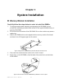
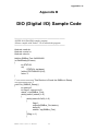
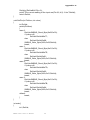
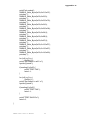
1
KEEX-2030 Industrial 3.5" Embedded SBC with Intel® Atom N270 User’s Guide KEEX-2030 User’s Manual I Contact Info: Quanmax Inc. 5F, No. 415, Ti-Ding Blvd. Sec. 2, NeiHu District, Taipei, Taiwan 114 Tel: +886-2-2799-2789 Fax: +886-2-2799-7399 Visit our site at: www.quanmax.com © 2008 Quanmax Inc. All rights reserved. The information in this user’s guide is provided for reference only. Quanmax does not assume any liability arising out of the application or use of the information or products described herein. This user’s guide may contain or reference information and products protected by copyrights or patents and does not convey any license under the patent rights of Quanmax, nor the rights of others. Quanmax is a registered trademark of Quanmax. All trademarks, registered trademarks, and trade names used in this user’s guide are the property of their respective owners. All rights reserved. This user’s guide contains information proprietary to Quanmax. Customers may reprint and use this user’s guide in other publications. Customers may alter this user’s guide and publish it only after they remove the Quanmax name, cover, and logo. Quanmax reserves the right to make changes without notice in product or component design as warranted by evolution in user needs or progress in engineering or manufacturing technology. Changes which affect the operation of the unit will be documented in the next revision of this user’s guide. Revision Date Edited by Changes 1.0 10/02/2008 SLee Initial Release 1.1 10/28/2008 SLee JP2 Correction 1.2 11/07/2008 SLee COM2/3/4 Correction 1.3 04/21/2009 SLee Table 12 updated 1.4 12/16/2009 SLee Correct RS232/422/485 pin assignment 1.5 01/26/2010 SLee Updated LVDS pin-out 1.6 06/29/2010 Zack Update Appendix DIO and Watchdog Timer Sample Code 1.7 07/13/2010 Zack Update DIO sample Code 1.8 10/21/2010 Zack Update Table 4 Default Setting 1.9 01/29/2011 Zack Add Remark on Table 3 about clear CMOS setting. KEEX-2030 User’s Manual II Content Content ....................................................... 3 Figures ....................................................... 4 Tables ........................................................ 5 Safety Instructions ............................................... 7 Before You Begin ...................................................................................... 7 When Working Inside a Computer ............................................................ 7 Preventing Electrostatic Discharge ........................................................... 8 Preface ...................................................... 10 How to Use This Guide........................................................................... 10 Unpacking .............................................................................................. 10 Regulatory Compliance Statements ....................................................... 10 Warranty Policy ...................................................................................... 11 Maintaining Your Computer .................................................................... 12 Chapter 1 Introduction .......................................... 15 Overview ................................................................................................ 15 Product Specifications ............................................................................ 16 System Block Diagram ........................................................................... 17 Mechanical Dimensions.......................................................................... 18 Chapter 2 Hardware Settings ..................................... 19 Overview ................................................................................................ 19 Jumper Settings and Pin Definitions ....................................................... 20 Jumper Settings ..................................................................................... 21 Rear Panel Pin Assignments .................................................................. 22 Main Board Pin Assignments .................................................................. 24 Chapter 3 System Installation ..................................... 32 Memory Module Installation .................................................................... 32 Chapter 4 AMI BIOS Setup ...................................... 34 Overview ................................................................................................ 34 Main Menu.............................................................................................. 35 Advanced Menu ..................................................................................... 36 Boot Menu .............................................................................................. 40 Chipset Menu ......................................................................................... 41 Power Menu ........................................................................................... 43 Security Menu ........................................................................................ 44 Exit Menu ............................................................................................... 45 Chapter 5 Driver Installation………………………………………………………………………………………………….…45 Appendix A System Resources……………………………………………………………………………………………………48 Appendix B DIO Sample Code ……………………………………………………………………………………………………52 Appendix C Watchdog Timer Sample Code ………………………………………………………………………56 KEEX-2030 User’s Manual 3 Figures Figure 1 Block Diagram ............................................................................................ 17 Figure 2 Mechanical Dimensions ............................................................................. 18 Figure 3 Jumper Connector...................................................................................... 19 Figure 4 Jumper and Connector Locations .............................................................. 20 Figure 5 Align the SO-DIMM Memory Module with the onboard socket ................... 32 Figure 6 Press down on the SO-DIMM Memory Module to lock it in place............... 32 KEEX-2030 User’s Manual 4 Tables Table 1 KEEX-2030 Specification ............................................................................. 16 Table 2 Jumper List .................................................................................................. 21 Table 3 JP1 Clear CMOS Selection.......................................................................... 21 Table 4 JP2 Power Mode Selection .......................................................................... 21 Table 5 JP3 Backlight & Panel Power Selection ....................................................... 21 Table 6 JP4 Backlight Enable Selection ................................................................... 21 Table 7 JP5 KB/MS Connector Selection ................................................................. 22 Table 8 JP6 USB POWER SELECT ......................................................................... 22 Table 9 Rear Panel Connector Descriptions ............................................................ 22 Table 10 USB1 2-Stack USB2.0 Type A Connector .................................................. 22 Table 11 LAN1 10/100/1000 Ethernet RJ-45 Connector........................................... 22 Table 12 COM1 RS-232/422/485 DB-9 Connector ................................................... 23 Table 13 CN7 PS/2 KB/MS Mini-DIN Connector ...................................................... 23 Table 14 CN2 DVI-I Connector ................................................................................. 23 Table 15 Connector List............................................................................................ 24 Table 16 ATX1 +12V Power Input Connector ........................................................... 24 Table 17 CFD1 CF Type II Connector ...................................................................... 25 Table 18CN1 Panel Backlight Wafer ........................................................................ 26 Table 19 CN3,4 Audio AMP Output Wafer ................................................................ 26 Table 20 CN5 Digital Input / Output Pin Header ....................................................... 26 Table 21 CN6 IrDA Connector .................................................................................. 26 Table 22 FP1 Front Panel 1 Pin Header ................................................................... 27 Table 23 FP2 Front Panel 2 Pin Header ................................................................... 27 Table 24 LVDS1 LVDS Panel Connector .................................................................. 27 Table 25 PCIE1 PCIE x 4 Slot .................................................................................. 28 Table 26 SATA2: SATA Connector ............................................................................ 28 Table 27 SATA1 Serial ATA & HDD Power Connector .............................................. 29 Table 28 USB2 USB2.0 Port 2, 3 Pin Header........................................................... 29 Table 29 USB3 USB2.0 Port 4, 5 Pin Header........................................................... 29 Table 30 USB4 USB2.0 Port 6, 7 Pin Header........................................................... 30 Table 31 COM2 RS-232 Port B Wafer ...................................................................... 30 Table 32 COM3 RS-232 Port B Wafer ...................................................................... 30 Table 33 COM4 RS-232 Port B Wafer ...................................................................... 31 Table 34 AUDIO1 Audio Output Wafer ..................................................................... 31 KEEX-2030 User’s Manual 5 Table 35 BIOS Main Menu ....................................................................................... 35 Table 36 IDE Device Setting Menu ........................................................................... 35 Table 37 System Information .................................................................................... 36 Table 38 Advanced Menu ......................................................................................... 36 Table 39 Onboard I/O Configuration ......................................................................... 37 Table 40 OnBoard Peripherals Configuration Settings ............................................. 38 Table 41 Trusted Computing .................................................................................... 39 Table 42 Hardware Health Configuration.................................................................. 39 Table 43 Boot Menu ................................................................................................. 40 Table 44 Chipset Menu ............................................................................................. 41 Table 45 Video Function Configuration..................................................................... 42 Table 46 Power Menu............................................................................................... 43 Table 47 Security Menu ............................................................................................ 44 Table 48 Exit Menu ................................................................................................... 45 KEEX-2030 User’s Manual 6 Safety Instructions Before You Begin Before handling the product, read the instructions and safety guidelines on the following pages to prevent damage to the product and to ensure your own personal safety. Refer to the “Advisories” section in the Preface for advisory conventions used in this user’s guide, including the distinction between Warnings, Cautions, Important Notes, and Notes. Always use caution when handling/operating a computer. Only qualified, experienced, authorized electronics service personnel should access the interior of a computer. The power supplies produce high voltages and energy hazards, which can cause bodily harm. Use extreme caution when installing or removing components. Refer to the installation instructions in this user’s guide for precautions and procedures. If you have any questions, please contact Quanmax Post-Sales Technical Support. WARNING High voltages are present inside the chassis when the unit’s power cord is plugged into an electrical outlet. Turn off system power, turn off the power supply, and then disconnect the power cord from its source before removing the chassis cover. Turning off the system power switch does not remove power to components. When Working Inside a Computer Before taking covers off a computer, perform the following steps: 1. Turn off the computer and any peripherals. 2. Disconnect the computer and peripherals from their power sources or subsystems to prevent electric shock or system board damage. This does not apply when hot swapping parts. KEEX-2030 User’s Manual 7 3. 4. Follow the guidelines provided in “Preventing Electrostatic Discharge” on the following page. Disconnect any telephone or telecommunications lines from the computer. In addition, take note of these safety guidelines when appropriate: To help avoid possible damage to system boards, wait five seconds after turning off the computer before removing a component, removing a system board, or disconnecting a peripheral device from the computer. When you disconnect a cable, pull on its connector or on its strain-relief loop, not on the cable itself. Some cables have a connector with locking tabs. If you are disconnecting this type of cable, press in on the locking tabs before disconnecting the cable. As you pull connectors apart, keep them evenly aligned to avoid bending any connector pins. Also, before connecting a cable, make sure both connectors are correctly oriented and aligned. CAUTION Do not attempt to service the system yourself except as explained in this user’s guide. Follow installation and troubleshooting instructions closely. Preventing Electrostatic Discharge Static electricity can harm system boards. Perform service at an ESD workstation and follow proper ESD procedure to reduce the risk of damage to components. Quanmax strongly encourages you to follow proper ESD procedure, which can include wrist straps and smocks, when servicing equipment. You can also take the following steps to prevent damage from electrostatic discharge (ESD): When unpacking a static-sensitive component from its shipping carton, do not remove the component’s antistatic packing material until you are ready to install the component in a computer. Just before unwrapping the antistatic packaging, be sure you are at an ESD workstation or grounded. This will discharge any static electricity that may have built up in your body. When transporting a sensitive component, first place it in an antistatic container KEEX-2030 User’s Manual 8 or packaging. Handle all sensitive components at an ESD workstation. If possible, use antistatic floor pads and workbench pads. Handle components and boards with care. Don’t touch the components or contacts on a board. Hold a board by its edges or by its metal mounting bracket. Do not handle or store system boards near strong electrostatic, electromagnetic, magnetic, or radioactive fields. KEEX-2030 User’s Manual 9 Preface How to Use This Guide This guide is designed to be used as step-by-step instructions for installation, and as a reference for operation, troubleshooting, and upgrades. NOTE Driver downloads and additional information are available under Downloads on our web site: www.quanmax.com. Unpacking When unpacking, follow these steps: 1. 2. 3. After opening the box, save it and the packing material for possible future shipment. Remove all items from the box. If any items listed on the purchase order are missing, notify Quanmax customer service immediately. Inspect the product for damage. If there is damage, notify Quanmax customer service immediately. Refer to “Warranty Policy” for the return procedure. Regulatory Compliance Statements This section provides the FCC compliance statement for Class A devices. FCC Compliance Statement for Class A Devices The product(s) described in this user’s guide has been tested and found to comply with the limits for a Class A digital device, pursuant to Part 15 of the FCC Rules. These limits are designed to provide reasonable protection against harmful KEEX-2030 User’s Manual 10 interference when the equipment is operated in a commercial environment. This equipment generates, uses, and can radiate radio frequency energy and, if not installed and used in accordance with the user’s guide, may cause harmful interference to radio communications. Operation of this equipment in a residential area (domestic environment) is likely to cause harmful interference, in which case the user will be required to correct the interference (take adequate measures) at their own expense. Changes or modifications not expressly approved by Quanmax could void the user's authority to operate the equipment. NOTE The assembler of a personal computer system may be required to test the system and/or make necessary modifications if a system is found to cause harmful interference or to be noncompliant with the appropriate standards for its intended use. Warranty Policy Limited Warranty Quanmax Inc.’s detailed Limited Warranty policy can be found under Support at www.quanmax.com. Please consult your distributor for warranty verification. The limited warranty is void if the product has been subjected to alteration, neglect, misuse, or abuse; if any repairs have been attempted by anyone other than Quanmax or its authorized agent; or if the failure is caused by accident, acts of God, or other causes beyond the control of Quanmax or the manufacturer. Neglect, misuse, and abuse shall include any installation, operation, or maintenance of the product other than in accordance with the user’s guide. No agent, dealer, distributor, service company, or other party is authorized to change, modify, or extend the terms of this Limited Warranty in any manner whatsoever. Quanmax reserves the right to make changes or improvements in any product without incurring any obligation to similarly alter products previously purchased. Return Procedure For any Limited Warranty return, please contact Support at www.quanmax.com and KEEX-2030 User’s Manual 11 login to obtain a Return Material Authorization (RMA) Number. If you do not have an account, send an email to [email protected] to apply for one. All product(s) returned to Quanmax for service or credit must be accompanied by a Return Material Authorization (RMA) Number. Freight on all returned items must be prepaid by the customer who is responsible for any loss or damage caused by common carrier in transit. Returns for Warranty must include a Failure Report for each unit, by serial number(s), as well as a copy of the original invoice showing the date of purchase. To reduce risk of damage, returns of product must be in a Quanmax shipping container. If the original container has been lost or damaged, new shipping containers may be obtained from Quanmax Customer Service at a nominal cost. Quanmax owns all parts removed from repaired products. Quanmax uses new and reconditioned parts made by various manufacturers in performing warranty repairs and building replacement products. If Quanmax repairs or replaces a product, its warranty term is not extended. Shipments not in compliance with this Limited Warranty Return Policy will not be accepted by Quanmax. Limitation of Liability In no event shall Quanmax be liable for any defect in hardware, software, loss, or inadequacy of data of any kind, or for any direct, indirect, incidental, or consequential damages in connection with or arising out of the performance or use of any product furnished hereunder. Quanmax’s liability shall in no event exceed the purchase price of the product purchased hereunder. The foregoing limitation of liability shall be equally applicable to any service provided by Quanmax or its authorized agent. Maintaining Your Computer Environmental Factors Temperature The ambient temperature within an enclosure may be greater than room ambient temperature. Installation in an enclosure should be such that the amount of air flow required for safe operation is not compromised. Consideration should be given to the maximum rated ambient temperature. Overheating can cause a variety of problems, including premature aging and failure of chips or mechanical failure of devices. KEEX-2030 User’s Manual 12 If the system has been exposed to abnormally cold temperatures, allow a two-hour warm-up period to bring it up to normal operating temperature before turning it on. Failure to do so may cause damage to internal components, particularly the hard disk drive. Humidity High-humidity can cause moisture to enter and accumulate in the system. This moisture can cause corrosion of internal components and degrade such properties as electrical resistance and thermal conductivity. Extreme moisture buildup inside the system can result in electrical shorts, which can cause serious damage to the system. Buildings in which climate is controlled usually maintain an acceptable level of humidity for system equipment. However, if a system is located in an unusually humid location, a dehumidifier can be used to maintain the humidity within an acceptable range. Refer to the “Specifications” section of this user’s guide for the operating and storage humidity specifications. Altitude Operating a system at a high altitude (low pressure) reduces the efficiency of the cooling fans to cool the system. This can cause electrical problems related to arcing and corona effects. This condition can also cause sealed components with internal pressure, such as electrolytic capacitors, to fail or perform at reduced efficiency. Power Protection The greatest threats to a system’s supply of power are power loss, power spikes, and power surges caused by electrical storms, which interrupt system operation and/or damage system components. To protect your system, always properly ground power cables and one of the following devices. Surge Protector Surge protectors are available in a variety of types and usually provide a level of protection proportional with the cost of the device. Surge protectors prevent voltage spikes from entering a system through the AC power cord. Surge protectors, however, do not offer protection against brownouts, which occur when the voltage drops more than 20 percent below the normal AC line voltage level. KEEX-2030 User’s Manual 13 Line Conditioner Line conditioners go beyond the overvoltage protection of surge protectors. Line conditioners keep a system’s AC power source voltage at a fairly constant level and, therefore, can handle brownouts. Because of this added protection, line conditioners cost more than surge protectors. However, line conditioners cannot protect against a complete loss of power. Uninterruptible Power Supply Uninterruptible power supply (UPS) systems offer the most complete protection against variations on power because they use battery power to keep the server running when AC power is lost. The battery is charged by the AC power while it is available, so when AC power is lost, the battery can provide power to the system for a limited amount of time, depending on the UPS system. UPS systems range in price from a few hundred dollars to several thousand dollars, with the more expensive unit s allowing you to run larger systems for a longer period of time when AC power is lost. UPS systems that provide only 5 minutes of battery power let you conduct an orderly shutdown of the system, but are not intended to provide continued operation. Surge protectors should be used with all UPS systems, and the UPS system should be Underwriters Laboratories (UL) safety approved. KEEX-2030 User’s Manual 14 Chapter 1 Introduction Overview The KEEX-2030 is an 3.5” Form Factor embedded single board computer (SBC) that combines the high performance and low power consumption of the Intel® Atom™ processor with Intel® 945GSE/ ICH7M chipset and supports DDR2 400/533 SODIMM up to 2GB. This SBC offers the latest performance, features and I/O interfaces at an extremely attractive price/performance ratio and measures 102mm x 146mm, a 75 percent space reduction over micro-ATX boards. The KEEX-2030 features DVI and 18-bit dual channel LVDS panel support, SATA, RS-232/422/485 serial port, Digital I/O, Gb/s Ethernet, USB 2.0, keyboard/mouse, and AC97” audio. PCIe x4 support provides expansion capability. Checklist SATA cable Y cable for keyboard & mouse Driver/ Manual CD Quick Installation Guide KEEX-2030 3.5” motherboard Features Intel® Atom Processor N270 Intel® 945GSE / ICH7-M DDR2 SO-DIMM Socket, total up to 2 GB SATA, PCIe x4 slot, CompactFlash socket Gb/s Ethernet, 8x USB 2.0 ports, 4x COM ports, DVI-I supported Watchdog Timer, Hardware Monitor, TPM 1.2 KEEX-2030 User’s Manual 15 Product Specifications CPU Support Intel® Atom™ N270 Chipset Intel® 945GSE + ICH7-M Memory 1x DDR2 400/533 SO-DIMM Socket, up to 2GB BIOS AMI Plug & Play BIOS – 8Mb SPI ROM Integrated on Intel® 945GSE Chipset Display 18-bit Dual channel LVDS support 1x DVI-I LAN Audio 1x RJ-45, Gigabit Ethernet (Realtek 8110SC Controller for KEEX-2030) 1x RJ-45, Fast Ethernet (Realtek 8100SC Controller for KEEX-2031) AC’97 ALC655 Codec with 2W Audio Amplifier Supports Line-in, Line-out & Microphone 2x SATA (one with onboard power connector) 1x CompactFlash socket Peripheral 8x USB 2.0 Support 4x COMs with Power Selection 4x DI/DO 1x Mini-Din PS/2 KB/ MS TPM Power Connector Expansion Watchdog Timer Hardware Monitor Dimensions Environmental Factors Certifications TPM 1.2 ATX-4P 1x PCIe x4 slot 1-255 step, can be set with software on Super I/O Operating voltage, CPU temperature and fan speed 3.5” Embedded Board (102 x 146 mm) Operation Temp: 0ºC - 60ºC Storage Temp.: -10ºC - 85ºC Humidity: 0% - 90% CE, FCC Class A Table 1 KEEX-2030 Specification KEEX-2030 User’s Manual 16 System Block Diagram Figure 1 Block Diagram KEEX-2030 User’s Manual 17 Mechanical Dimensions Figure 2 Mechanical Dimensions KEEX-2030 User’s Manual 18 Chapter 2 Hardware Settings Overview This chapter provides the definitions and locations of jumpers, headers, and connectors. Jumpers The product has several jumpers which must be properly configured to ensure correct operation. Figure 3 Jumper Connector For a three-pin jumper (see figure above), the jumper setting is designated “1-2” when the jumper connects pins 1 and 2. The jumper setting is designated “2-3” when pins 2 and 3 are connected and so on. You will see that one of the lines surrounding a jumper pin is thick, which indicates pin No.1. To move a jumper from one position to another, use needle-nose pliers or tweezers to pull the pin cap off the pins and move it to the desired position. KEEX-2030 User’s Manual 19 Jumper Settings and Pin Definitions For jumper and connector locations, please refer to the diagrams below. Figure 4 Jumper and Connector Locations KEEX-2030 User’s Manual 20 Jumper Settings To ensure correct system configuration, the following section describes how to set the jumpers to enable/disable or change functions. For jumper descriptions, please refer to the table below. Table 2 Jumper List Label JP1 JP2 JP3 JP4 JP5 JP6 Function Clear CMOS Selection Power Mode Selection Backlight & Panel Power Selection Backlight Enable Selection KB/MS Connector Selection USB POWER SELECT Table 3 JP1 Clear CMOS Selection Jumper Open Short 1 2 Status Normal Operation (Default) Clear CMOS Pitch:2.54mm [YIMTEX 3321*02SAGR(6T)] Remark: You must go to BIOS EXIT menu to do “Load Optimal Defaults” after clear CMOS. Please refer to table 48. Table 4 JP2 Power Mode Selection Jumper Open Short Status ATX Mode (Default) AT Mode Pitch:2.54mm [YIMTEX 3321*02SAGR(6T)] Remark: Please remove jumper if you are using ATX mode. Table 5 JP3 Backlight & Panel Power Selection Jumper 1 2 Setting 1-3 3-5 2-4 4-6 Status Backlight Power = +12V (Default) Backlight Power = +5V Panel Power = +3.3V (Default) Panel Power = +5V Pitch:2.54mm [YIMTEX 3362*03SAGR] Table 6 JP4 Backlight Enable Selection 1 2 3 Jumper 1-2 2-3 Status Active High (Default) Active Low Pitch:2.0mm [YIMTEX 3291*03SAGR(6T)] KEEX-2030 User’s Manual 21 Table 7 JP5 KB/MS Connector Selection Pin 1 3 5 7 9 Signal +5VSB KBCLK_SIO KBCLK_CN7 MSCLK_SIO MSCLK_CN7 Pin 2 4 6 8 10 Signal GND KBDAT_ SIO KBDAT_CN7 MSDAT_SIO MSDAT_CN7 Pitch:2.54mm [YIMTEX 3322*05SAGR(6T] Table 8 JP6 USB POWER SELECT Jumper 1-2 2-3 1 2 3 Status +5VSB (Default) +5V Pitch:2.0mm [YIMTEX 3291*03SAGR(6T)] Rear Panel Pin Assignments Table 9 Rear Panel Connector Descriptions Label USB1 LAN1 COM1 CN7 CN2 Function USB2.0 Port 0, 1 Type A Connector 10/100/1000 Ethernet RJ-45 Connector RS-232/422/485 Port A DB-9 Connector PS/2 KB/MS Mini-DIN Connector DVI Connector Table 10 USB1 2-Stack USB2.0 Type A Connector Pin 1 2 3 4 Signal Name +5V USB1USB1+ GND Pin 5 6 7 8 Signal Name +5V USB0USB0+ GND USB DIP 4*2P 90D 1~3u [KUON YI KS-002-ANB-L] Table 11 LAN1 10/100/1000 Ethernet RJ-45 Connector Pin 1 2 3 4 Signal Tx+ TxRx+ NC Pin 5 6 7 8 Signal NC RxNC NC RJ45+TFM+LED 10/100/1000 14P DIP 90° [Speed Tech P26@P0C-4AM7(XA)] KEEX-2030 User’s Manual 22 Table 12 COM1 RS-232/422/485 DB-9 Connector Pin RS232 RS422 (COM1*) 1 2 3 4 5 6 7 8 9 DCD, Data carrier detect RXD, Receive data TXD, Transmit data DTR, Data terminal ready GND, ground DSR, Data set ready RTS, Request to send CTS, Clear to send RI, Ring indicator TXRX+ TX+ RXGND N/A N/A N/A N/A RS485 Half Duplex (COM1*) DATAN/A DATA+ N/A GND N/A N/A N/A N/A D-SUB 9MR 9P MALE [SM1001P01012PN] Table 13 CN7 PS/2 KB/MS Mini-DIN Connector Pin 1 2 3 4 5 6 Signal KBDAT MSDAT GND +5V KBCLK MSCLK MINI DIN DIP 6P RIGHT ANGLE FEMALE BLACK METAL SHIELD [Kuon Yi DN-508I-6B3-L ] Table 14 CN2 DVI-I Connector Pin 1 3 5 7 9 11 13 15 17 19 21 23 Signal Name TX2N GND TX5P SD_DATA TX1N GND TX4P VGA_EN TX0N GND TX6P TCLP Pin 2 4 6 8 10 12 14 16 18 20 22 24 Signal Name TX2P TX5N SD_CLK VSYNC TX1P TX4N VGA_PWR HPD TX0P TX6N GND TXLN DVI 29P DIP (F) 90D H/D CONNECTOR WHITE [WIN WIN WDVI-29ABNW11U] KEEX-2030 User’s Manual 23 Main Board Pin Assignments Table 15 Connector List Label ATX1 CFD1 CN1 CN3,4 CN5 CN6 DIMM1 FP1 FP2 LVDS1 PCIE1 SATA1 SATA2 USB2 USB3 USB4 COM2 COM3 COM4 AUDIO1 Function +12V Power Input Connector CF Type II Connector Panel Backlight Wafer Audio AMP Output Wafer Digital Input / Output Pin Header IR Pin Header DDR2 Memory SO-DIMM Socket Front Panel 1 Pin Header Front Panel 2 Pin Header LVDS Panel Connector PCIE x 4 Slot Serial ATA & HDD Power Connector Serial ATA Connector USB2.0 Port 2, 3 Pin Header USB2.0 Port 4, 5 Pin Header USB2.0 Port 6, 7 Pin Header RS-232 Port B With Power Wafer RS-232 Port C With Power Wafer RS-232 Port D With Power Wafer AUDIO OUT Wafer Table 16 ATX1 +12V Power Input Connector Pin Signal Name 1 GND 2 GND 3 +12V 4 +12V [YIMTEX 576MWA2*02STR] KEEX-2030 User’s Manual 24 Table 17 CFD1 CF Type II Connector Pin Signal Name Pin Signal Name 1 GND 26 GND 2 IDE Data 3 27 IDE Data 11 3 IDE Data 4 28 IDE Data 12 4 IDE Data 5 29 IDE Data 13 5 IDE Data 6 30 IDE Data 14 6 IDE Data 7 31 IDE Data 15 7 IDE Chip select 1# 32 IDE Chip select 3# 8 GND 33 GND 9 GND 34 IDEIOR# 10 GND 35 IDEIOW# 11 GND 36 +5V 12 GND 37 IDEIRQ 13 +5V 38 +5V 14 GND 39 PCSEL 15 GND 40 NC 16 GND 41 Reset IDE 17 GND 42 IDEIORDY 18 SDA2 43 DREQ 19 IDE Address 1 44 DACK# 20 IDE Address 0 45 IDE activity 21 IDE Data 0 46 PDIAG# 22 IDE Data 1 47 IDE Data 8 23 IDE Data 2 48 IDE Data 9 24 IOIS16# 49 IDE Data 10 25 GND 50 GND CF1A-71041-00E01 KEEX-2030 User’s Manual 25 Table 18 CN1 Panel Backlight Wafer Pin Signal Name 1 NC 2 BL_ADJ 3 GND 4 +5V / +12V ** 5 +5V / +12V ** 6 GND 7 BL_EN / BL_EN# * *Selected by JP4 ** Selected by JP3 Pitch:1.25mm [YIMTEX 501MW1*07MTRR] Table 19 CN3,4 Audio AMP Output Wafer Pin Signal Name 1 Speaker+ 2 Speaker- Pitch=2.0mm WAFER [YIMTEX 503PW1*02STR] Table 20 CN5 Digital Input / Output Pin Header Pin Signal Pin Signal 1 Digital Output 0 2 Digital Input 0 3 Digital Output 1 4 Digital Input 1 5 Digital Output 2 6 Digital Input 2 7 Digital Output 3 8 Digital Input 3 9 +5V 10 GND Pitch:2.0mm [YIMTEX 3292*05SAGR(6T)] Table 21 CN6 IrDA Connector Pin Signal Name 1 +5V 2 NC 3 RXDB 4 GND 5 TXDB Pitch:2.54mm [YIMTEX 3321*05SAGR-02] KEEX-2030 User’s Manual 26 Table 22 FP1 Front Panel 1 Pin Header RSTBTN HLED + 1 2 + - SPKR + - 8 7 - Pin Signal Pin Signal 1 Reset Button + 2 Speaker + 3 Reset Button - 4 NC 5 HDD LED + 6 NC 7 HDD LED - 8 Speaker - Pitch:2.54mm [YIMTEX 3322*04SAGR(6T)] Table 23 FP2 Front Panel 2 Pin Header + 1 PLED 2 + - PWRBTN KLOCK SMD + - 9 10 SMC Pin Signal Pin Signal 1 Power LED + 2 Power Button + 3 NC 4 Power Button - 5 Power LED - 6 NC 7 Keyboard Lock 8 SMBus Data 9 GND 10 SMBus Clock Pitch:2.54mm [YIMTEX 3322*05SAGR(6T] Table 24 LVDS1 LVDS Panel Connector Pin Signal Name Pin Signal Name 1 LVDS_A0- 16 LVDS_B1+ 2 LVDS_A0+ 17 GND 3 LVDS_A1- 18 LVDS_B2- 4 LVDS_A1+ 19 LVDS_B2+ 5 LVDS_A2- 20 LVDSBCLK- 6 LVDS_A2+ 21 LVDS_BCLK+ 7 GND 22 NC 8 LVDS_ACLK- 23 NC 9 LVDS_ACLK+ 24 GND 10 NC 25 DCC_DAT 11 NC 26 VDDEN 12 LVDS_B0- 27 DCC_CLK 13 LVDS_B0+ 28 +3.3V / +5V * 14 GND 29 +3.3V / +5V * 15 LVDS_B1- 30 +3.3V / +5V * * Selected by JP3 Pitch:1mm [JAE FI-X30SSL-HF] KEEX-2030 User’s Manual 27 Table 25 PCIE1 PCIE x 4 Slot PIN A32 A31 A30 A29 A28 A27 A26 A25 A24 A23 A22 A21 A20 A19 A18 A17 A16 A15 A14 A13 A12 A11 A10 A9 A8 A7 A6 A5 A4 A3 A2 A1 SIGNAL RESERVED GND PERN3 PERP3 GND GND PERN2 PERP2 GND GND PERN1 PERP1 GND RESERVED GND PERN0 PERP0 GND REFCLK+ REFCLKGND PERST# +3.3V +3.3V JTAG5 JTAG4 JTAG3 JTAG2 GND +12V +12V PRSNT1# PIN B32 B31 B30 B29 B28 B27 B26 B25 B24 B23 B22 B21 B20 B19 B18 B17 B16 B15 B14 B13 B12 B11 B10 B9 B8 B7 B6 B5 B4 B3 B2 B1 SIGNAL GND PRSNT2# RESERVED GND PETN3 PETP3 GND GND PETN2 PETP2 GND GND PETN1 PETP1 GND PRSNT2# GND PETN0 PETP0 GND RESERVED WAKE# +3.3VAUX JTAG1 +3.3V GND SMDATA SMCLK GND RESERVED +12V +12V PCI 32*2P EXPRESS 180D(F) [WIN WIN WPES-064AN43B22UWS] Table 26 SATA2: SATA Connector Pin Signal Name 1 GND 2 TX+ 3 TX- 4 GND 5 RX- 6 RX+ 7 GND 7P 180D SATA CONNECTOR BLUE [FOXCONN LD1807V-S52U] KEEX-2030 User’s Manual 28 Table 27 SATA1 Serial ATA & HDD Power Connector Pin S1 Signal Name GND Pin P5 Signal Name GND S2 TX+ P6 GND S3 TX- P7 +5V S4 GND P8 +5V S5 RX- P9 +5V S6 RX+ P10 GND S7 GND P11 GND P1 +3.3V P12 GND P2 +3.3V P13 +12V P3 +3.3V P14 +12V P4 GND P15 +12V 7P+15P MALE 180D SATA CONNECTOR BLACK [WIN WIN WATH-22DLBGU4] Table 28 USB2 USB2.0 Port 2, 3 Pin Header Pin Signal Name Pin Signal Name 1 +5V 2 +5V 3 USB2- 4 USB3- 5 USB2+ 6 USB3+ 7 GND 8 GND 9 KEY 10 GND Pitch:2.54mm [YIMTEX 3322*05SAGR(6T) -09] Table 29 USB3 USB2.0 Port 4, 5 Pin Header Pin Signal Name Pin Signal Name 1 +5V 2 +5V 3 USB4- 4 USB5- 5 USB4+ 6 USB5+ 7 GND 8 GND 9 KEY 10 GND Pitch:2.54mm [YIMTEX 3322*05SAGR(6T) -09] KEEX-2030 User’s Manual 29 Table 30 USB4 USB2.0 Port 6, 7 Pin Header Pin Signal Name Pin Signal Name 1 +5V 2 +5V 3 USB6- 4 USB7- 8 5 USB6+ 6 USB7+ 10 7 GND 8 GND 9 KEY 10 GND 1 2 3 4 5 6 7 Pitch:2.54mm [YIMTEX 3322*05SAGR(6T) -09] Table 31 COM2 RS-232 Port B Wafer Pin Signal 1 DCD, Data carrier detect 2 DSR, Data set ready 3 RXD, Receive data 4 RTS, Request to send 5 TXD, Transmit data 6 CTS, Clear to send 7 DTR, Data terminal ready 8 RI, Ring indicator 9 GND, ground 10 +5V Pitch: 1.25mm WAFER [YIMTEX 501MW1*10STR] Table 32 COM3 RS-232 Port B Wafer Pin Signal 1 DCD, Data carrier detect 2 DSR, Data set ready 3 RXD, Receive data 4 RTS, Request to send 5 TXD, Transmit data 6 CTS, Clear to send 7 DTR, Data terminal ready 8 RI, Ring indicator 9 GND, ground 10 +5V Pitch: 1.25mm WAFER [YIMTEX 501MW1*10STR] KEEX-2030 User’s Manual 30 Table 33 COM4 RS-232 Port B Wafer Pin Signal 1 DCD, Data carrier detect 2 DSR, Data set ready 3 RXD, Receive data 4 RTS, Request to send 5 TXD, Transmit data 6 CTS, Clear to send 7 DTR, Data terminal ready 8 RI, Ring indicator 9 GND, ground 10 +5V Pitch: 1.25mm WAFER [YIMTEX 501MW1*10STR] Table 34 AUDIO1 Audio Output Wafer Pin Signal 1 LOUT_R 2 GND 3 LOUT_L 4 LIN_R 5 MIC 6 LIN_L Pitch:2.5mm WAFER [YIMTEX 510XW1*06STR] KEEX-2030 User’s Manual 31 Chapter 3 System Installation Memory Module Installation Carefully follow the steps below in order to install the DIMMs: 1. 2. 3. To avoid generating static electricity and damaging the SO-DIMM, ground yourself by touching a grounded metal surface or use a ground strap before you touch the SO-DIMM. Do not touch the connectors of the SO-DIMM. Dirt or other residue may cause a malfunction. Hold the SO-DIMM with its notch aligned with the memory socket of the board and insert it at a 30-degree angle into the socket. Figure 5 Align the SO-DIMM Memory Module with the onboard socket 4. 5. Fully insert the module into the socket until a “click” is heard. Press down on the SO-DIMM so that the tabs of the socket lock on both sides of the module Figure 6 Press down on the SO-DIMM Memory Module to lock it in place KEEX-2030 User’s Manual 32 Removing a DIMM: To remove the SO-DIMM, use your fingers or a small screwdriver to carefully push away the tabs that secure either side of the SO-DIMM. Lift it out of the socket. Make sure you store the SO-DIMM in an anti-static bag. The socket must be populated with memory modules of the same size and manufacturer. KEEX-2030 User’s Manual 33 Chapter 4 AMI BIOS Setup Overview This chapter provides a description of the AMI BIOS. The BIOS setup menus and available selections may vary from those of your product. For specific information on the BIOS for your product, please contact Quanmax. NOTE: The BIOS menus and selections for your product may vary from those in this chapter. For the BIOS manual specific to your product, please contact Quanmax AMI's ROM BIOS provides a built-in Setup program, which allows the user to modify the basic system configuration and hardware parameters. The modified data will be stored in a battery-backed CMOS, so that data will be retained even when the power is turned off. In general, the information saved in the CMOS RAM will not need to be changed unless there is a configuration change in the system, such as a hard drive replacement or when a device is added. It is possible for the CMOS battery to fail, which will cause data loss in the CMOS only. If this happens you will need to reconfigure your BIOS settings. KEEX-2030 User’s Manual 34 Main Menu The BIOS Setup is accessed by pressing the DEL key after the Power-On Self-Test (POST) memory test begins and before the operating system boot begins. Once you enter the BIOS Setup Utility, the Main Menu will appear on the screen. The Main Menu provides System Overview information and allows you to set the System Time and Date. Use the “<” and “>” cursor keys to navigate between menu screens. Table 35 BIOS Main Menu BIOS SETUP UTILITY Main Advanced Boot Chipset System Date System Time Power [Mon 01/21/2008] [10:18:15] > Primary IDE Master :[Not Detected] > Secondary IDE Master :[Not Detected] Exit Use [ENTER], [TAB] or [SHIFT-TAB] to select a field. Use [+] or [-] to configure system Time. :[Not Detected] > Primary IDE Slave Security <> Select Screen ↑↓ Select Item +- Change Field Tab Select Field F1 General Help F10 Save and Exit ESC Exit > System Information V02.61 (C)Copyright 1985-2006, American Megatrends, Inc. Below table is described for Primary IDE Master, Primary IDE Slave, Secondary IDE Master, Secondary IDE Slave setting. Table 36 IDE Device Setting Menu BIOS SETUP UTILITY Main Advanced Primary Master Device Boot Chipset Security [Auto] [Auto] [Auto] <> Select Screen ↑↓ Select Item +- Change Field Tab Select Field F1 General Help F10 Save and Exit ESC Exit V02.61 (C)Copyright 1985-2006, American Megatrends, Inc. KEEX-2030 User’s Manual Exit Disable: Disables LBA Mode. Auto: Enables LBA Mode if the device supports it and the device is not already formatted with LBA Mode disabled. :Not Detected LBA/ Large Mode DMA Mode S.M.A.R.T Power 35 LBA/ Large Mode Enables or disables the LBA (Logical Block Addressing)/ Large mode. Setting to Auto enables the LBA mode if the device supports this mode, and if the device was not previously formatted with LBA mode disabled. Options: Disabled, Auto DMA Mode Options: Auto, SWDMA, MWDMA, UDMA mode S.M.A.R.T SMART stands for Smart Monitoring, Analysis, and Reporting Technology. It allows AMIBIOS to use the SMART protocol to report server system information over a network. Options: Auto, Disabled, Enabled Table 37 System Information BIOS SETUP UTILITY Main Advanced AMIBIOS Version Build Date: Boot Chipset Power Security Exit : 1.0 :08/20/08 <> Select Screen ↑↓ Select Item +- Change Field Tab Select Field F1 General Help F10 Save and Exit ESC Exit Processor Genuine Intel® CPU N270 @ 1.60GHz Speed :1600MHz Count :1 System Memory Size :1016MB V02.61 (C)Copyright 1985-2006, American Megatrends, Inc. Advanced Menu Table 38 Advanced Menu BIOS SETUP UTILITY Main Advanced Boot Chipset Power Security Advanced Settings Warning: Setting wrong values in below sections may cause system to malfunction. <> Select Screen ↑↓ Select Item +- Change Field Tab Select Field F1 General Help F10 Save and Exit ESC Exit > I/O Configuration > OnBoard Peripherals Configuration > Trusted Computing > Hardware Health Configuration V02.61 (C)Copyright 1985-2006, American Megatrends, Inc. Press <Enter> to select a sub-menu for detailed options. KEEX-2030 User’s Manual 36 Exit Table 39 Onboard I/O Configuration BIOS SETUP UTILITY Main Advanced Boot Onboard I/O Configuration COM1 Address COM1 IRQ COM1 Function Type COM1 Pin9 Voltage COM2 Address COM2 IRQ COM2 Pin9 Voltage COM3 Address COM3 IRQ COM3 Mode COM3 Pin9 Voltage COM4 Address COM4 IRQ COM4 Mode COM4 Pin9 Voltage Chipset Power Security [3F8] [4] [RS232] [Normal] [2F8] [4] [Normal] [3E8] [11] [Normal] [Normal] [2E8] [11] [Normal] [Normal] <> Select Screen ↑↓ Select Item +- Change Field Tab Select Field F1 General Help F10 Save and Exit ESC Exit V02.61 (C)Copyright 1985-2006, American Megatrends, Inc. COM1 Address Options: Disabled, 3F8, 3E8, 2E8 COM1 IRQ Options: 3, 4, 10, 11 COM1 Function Type Options: RS232, RS422, RS485 COM1 Pin9 Voltage Options: Normal, 5V, 12V COM2 Address Options: Disabled, 2F8, 3E8, 2E8 COM 2 IRQ Options: 3, 4, 10, 11 COM2 Pin9 Voltage Options: Normal, 5V, 12V COM3 Address Options: Disabled, 3F8, 2F8, 3E8, 2E8, 2F0, 2E0 COM3 IRQ Options: 3, 4, 10, 11 COM3 Mode Options: Normal, IrDA, ASK IR, Smart Card Reader COM3 Pin9 Voltage Options: Normal, 5V, 12V COM4 Address Options: Disabled, 3F8, 2F8, 3E8, 2E8, 2F0, 2E0 KEEX-2030 User’s Manual Exit Allow BIOS to Select Serial Port1 Base Address. 37 COM4 IRQ Options: 3, 4, 10, 11 COM4 Mode Options: Normal, IrDA, ASK IR, Smart Card Reader COM4 Pin9 Voltage Options: Normal, 5V, 12V Table 40 OnBoard Peripherals Configuration Settings BIOS SETUP UTILITY Main Advanced Boot OnBoard Peripherals Configuration Settings USB Controller USB Device Legacy Support Audio Controller Onboard LAN Controller Onboard LAN OPTROM Chipset Power Security Options [Enable] [Enable] [Enable] [Enable] [Enable] Disabled Enabled <> Select Screen ↑↓ Select Item +- Change Field Tab Select Field F1 General Help F10 Save and Exit ESC Exit V02.61 (C)Copyright 1985-2006, American Megatrends, Inc. USB Controller Options: Enabled, Disabled USB Device Legacy Support Options: Enabled, Disabled, Auto Audio Controller Options: Enabled, Disabled Onboard LAN Controller Options: Enabled, Disabled Onboard LAN OPTROM Options: Enabled, Disabled KEEX-2030 User’s Manual 38 Exit Table 41 Trusted Computing BIOS SETUP UTILITY Main Advanced Boot Trusted Computing TCG/TPM SUPPORT Chipset Power Security Exit Enable/ Disable TPM TCG (TPM 1.1/1.2) supp in BIOS [NO] <> Select Screen ↑↓ Select Item +- Change Field Tab Select Field F1 General Help F10 Save and Exit ESC Exit V02.61 (C)Copyright 1985-2006, American Megatrends, Inc. TCG/TPM SUPPORT Options: No, Yes Table 42 Hardware Health Configuration BIOS SETUP UTILITY Main Advanced Hardware Health Configuration CPU Warning Temperature CPU Shutdown Temperature Temperature Sensor #1 Temperature Sensor #1 +VCORE +1.05V +3.3V +5V +12V +1.8v +VCC RTC Boot Chipset Power Security [Disabled] [Disabled] :89°C/ 192°F :54°C/ 129°F :1.136 V :1.040 V :3.166 V :4.958 V :11.182 V :1.758 V :3.365 V <> Select Screen ↑↓ Select Item +- Change Field Tab Select Field F1 General Help F10 Save and Exit ESC Exit V02.61 (C)Copyright 1985-2006, American Megatrends, Inc. KEEX-2030 User’s Manual 39 Exit Boot Menu Table 43 Boot Menu BIOS SETUP UTILITY Main Advanced Boot Chipset Power Boot Settings > Quick Boot > Bootup Num-Lock > Wait For ’F1’ If Error > Hit ’DEL’Message Display [Enabled] [ON] [Enabled] [Enabled] Security Exit Allow BIOS to Skip certain tests while booting. This will decrease the time needed to boot the system. <> Select Screen ↑↓ Select Item +- Change Field Tab Select Field F1 General Help F10 Save and Exit ESC Exit V02.61 (C)Copyright 1985-2006, American Megatrends, Inc. Quick Boot Enabling this item allows BIOS to skip some Power On Self Tests (POST) while booting to decrease the time needed to boot the system. When set to [Disabled], BIOS performs all the POST items. Options: Disabled, Enabled Bootup Num-Lock [On] Allow you to select the power-on state for the NumLock. Options: Off, On Wait for ‘F1’ If Error [Enabled] When set to Enabled, the system waits for F1 key to be pressed when error occurs. Options: Disabled, Enabled Hit ‘DEL’ Message Display [Enabled] When set to Enabled, the system displays the message ‘Press DEL to run Setup’ during POST. Options: Disabled, Enabled KEEX-2030 User’s Manual 40 Chipset Menu Table 44 Chipset Menu BIOS SETUP UTILITY Main Advanced Boot Chipset Power Security Exit Options Chipset Settings DRAM Frequency [Auto] Boots Graphic Adapter Priority Internal Graphics Mode Select Hyper Threading Technology [PEG/PCI] [Enabled, 8MB] [Enabled] > Video Function Configuration Auto 400 MHz 533 MHz <> Select Screen ↑↓ Select Item +- Change Field Tab Select Field F1 General Help F10 Save and Exit ESC Exit V02.61 (C)Copyright 1985-2006, American Megatrends, Inc. DRAM Frequency Options: Auto, 400 MHz, 533MHz Boots Graphic Adapter Priority Select which graphics controller to use as the primary boot device. Options: IGD, PCI/IGD, PCI/PEG, PEG/IGD, PEG/PCI Internal Graphics Mode Select Select the amount of system memory used by the Internal graphics device. Options: Disabled, Enabled 1MB, Enabled 8M Hyper Threading Technology Options: Disabled, Enabled KEEX-2030 User’s Manual 41 Video Function Configuration Table 45 Video Function Configuration BIOS SETUP UTILITY Main Advanced Boot Power Chipset Security Options Video Function Configuration DVMT Mode Select DVMT/FIXED Memory [DVMT Mode] [128M] Boot Display Device Flat Panel Type Local Flat Panel Scaling Panel BackLight Voltage [Auto] [800x600 [Auto] [0.0] Fixed Mode DVMT Mode Combo Mode 18Bit 1C] <> Select Screen ↑↓ Select Item +- Change Field Tab Select Field F1 General Help F10 Save and Exit ESC Exit V02.61 (C)Copyright 1985-2006, American Megatrends, Inc. DVMT Mode Select Options: Fixed Mode, DVMT Mode, Combo Mode DVMT/FIXED Memory Options: 64MB, 128MB, Maximum DVMT Boot Display Device Options: VGA, DVI, LVDS, VGA+LVDS Flat Panel Type Options: 640x480 18Bit 1CH, 800x600 18Bit 1CH, 1024x768 18Bit 1CH, 1280x800 18Bit 1Ch Local Flat Panel Scaling Options: Auto, Forced Scaling, Disabled Panel BackLight Voltage Options: Min 0.0V, Max: 5.0V KEEX-2030 User’s Manual 42 Exit Power Menu Table 46 Power Menu BIOS SETUP UTILITY Main Advanced Power Management Setting ACPI Function Suspend mode Repost Video on S3 Resume Suspend Time Out Restore on AC Power Loss Resume By USB Device Resume On PME# Resume On RTC Alarm Boot Chipset [Enabled] [S1 (POS)] [No] [Disabled] [Last State] [Disabled] [Disabled] [Disabled] Power Security Exit Select the ACPI state used for System Suspend <> Select Screen ↑↓ Select Item +- Change Field Tab Select Field F1 General Help F10 Save and Exit ESC Exit V02.61 (C)Copyright 1985-2006, American Megatrends, Inc. ACPI Function Enable/ Disable ACPI support for Operating System. ENABLE: If OS supports ACPI, DISABLE: IF OS Does not support ACPI. Suspend mode Options: S1 (POS), S3 (STR) Repost Video on S3 Resume Determines whether to invoke VGA BIOS post on S3/STR resume. Options: No, Yes Suspend Time Out Options: Disabled, 1 Min, 2 Min, 4 Min, 8 Min, 10 Min, 20 Min, 30 Min, 40 Min, 50 Min, 60 Min Restore on AC Power Loss Options: Power OFF, Power ON, Last State Resume By USB Device Options: Disabled, Enabled Resume On PME# Options: Disabled, Enabled Resume On RTC Alarm Options: Disabled, Enabled KEEX-2030 User’s Manual 43 Security Menu Table 47 Security Menu BIOS SETUP UTILITY Main Advanced Boot Chipset Power Security Exit Install or Change the password. Security Setting Supervisor Password :Not Installed User Password :Not Installed <> Select Screen ↑↓ Select Item +- Change Field Tab Select Field F1 General Help F10 Save and Exit ESC Exit Change Supervisor Password Change User Password V02.61 (C)Copyright 1985-2006, American Megatrends, Inc. Change Supervisor Password Select this item to set or change the supervisor password. The Supervisor Password item on top of the screen displays the default Not Installed. After you have set a password, this item displays Installed. Change User Password Select this item to set or change the user password. The User Password item on top of the screen displays the default Not Installed. After you have set a password, this item displays Installed. KEEX-2030 User’s Manual 44 Exit Menu Table 48 Exit Menu BIOS SETUP UTILITY Main Advanced Boot Chipset Power Security Exit Exit Setting Exit System Setup after saving Save Changes and Exit the changes. Discard Changes and Exit Discard Changes F10 key can be used for this operation. Load Optimal Defaults Load Failsafe Defaults <> Select Screen ↑↓ Select Item +- Change Field Tab Select Field F1 General Help F10 Save and Exit ESC Exit V02.61 (C)Copyright 1985-2006, American Megatrends, Inc. Save Changes and Exit Exit system setup after saving the changes. Once you are finished making your selections, choose this option from the Exit menu to ensure the values you selected are saved to the CMOS RAM. The CMOS RAM is sustained by an onboard backup battery and stays on even when the PC is turned off. When you select this option, a confirmation window appears. Select [Yes] to save changes and exit. Discard Changes and Exit Exit system setup without saving any changes. Select this option only if you do not want to save the changes that you made to the Setup program. If you made changes to fields other than system date, system time, and password, the BIOS asks for a confirmation before exiting. Discard Changes Discards changes done so far to any of the setup values. This option allows you to discard the selections you made and restore the previously saved values. After selecting this option, a confirmation appears. Select [Yes] to discard any changes and load the previously saved values. Load Optimal Defaults Load Optimal Default values for all the setup values. This option allows you to load optimal default values for each of the parameters on the Setup menus, which will provide the best performance settings for your system. The F9 key can be used for this operation. KEEX-2030 User’s Manual 45 Load Failsafe Defaults Load Optimal Default values for all the setup values. This option allows you to load failsafe default values for each of the parameters on the Setup menus, which will provide the most stable performance settings. The F8 key can be used for this operation. KEEX-2030 User’s Manual 46 Chapter 5 Driver Installation If your KEEX-2030 does not come with an operating system pre-installed, you will need to install an operating system and the necessary drivers to operate it. After you have finished assembling your system and connected the appropriate power source, power it up using the ATX Power Switch and install the desired operating system. You can download the drivers for the KEEX-2030 from the Quanmax website at www.quanmax.com and install as instructed there. For other operating systems, please contact Quanmax. NOTE When the system reboots without connecting the CRT, there might be no image on screen when you insert the CRT/VGA cable. Please pressing <Ctrl>+<Alt>+<F3> simultaneously to show the image on screen. KEEX-2030 User’s Manual 47 Appendix A Appendix A System Resources Interrupt Request (IRQ) Lines IRQ # Used For 0 Timer0 1 keyboard controller 2 Cascade 3 COM2 4 COM1 5 Free 6 Floppy disk controller 7 Free 8 Real Time Clock 9 ACPI-Compliant System 10 Free 11 COM3&4 12 PS/2 Mouse 13 Floating point unit (FPU / NPU / Math coprocessor) 14 Primary IDE channel 15 Secondary IDE channel Comment Note (1) Note (1) Note (1) Note (1) Note (1) Note (1) Note (1) Note: If the “Used For” device is disabled in setup, the corresponding interrupt is available for other devices. KEEX-2030 User’s Manual 48 Appendix A DMA Channels DMA # 0 1 2 3 Used For Memory Refresh Sound Floppy disk controller free Comment Note (1) Note (1) Unavailable if LPT used in ECP mode. 4 Cascade 5 Sound Note (1) 6 free 7 free Note: If the "Used For" device is disabled in setup, the corresponding interrupt is available for other devices. Memory Mapping Upper Memory C0000h - CBFFFh CC000h - CFFFFh CD000h - CDFFFh E0000h - FFFFFh PCI Devices PCI Device LAN Comment No Yes System BIOS No PCI Interrupt INTA PCI Express Devices PCIe Device PCIe x1 Slot 1 Inter-IC Bus (I2C) I2C Address A0h Used For VGA BIOS LAN Option ROM PCIe Interrupt INTC Comment AD20 Comment Used For DDR2-RAM DIMM Socket 0 Address KEEX-2030 User’s Manual 49 Comment Appendix A I/O Address Map I/O Address 00h – 0Fh C0h – DFh 20h, 21h 2Eh, 2Fh A0h, A1h 40h – 43h (XT/AT) 44h – 47h (PS/2) 60h – 64h 90h – 96h F0h – FFh 170h – 177h 1F0h – 1F7h 200h – 22Fh 220h – 22Fh 279h, A79h A15h, A16h 2E8h – 2EFh 2F8h – 2FFh 378h – 37Ah 3B0h – 3BFh 3C0h – 3CFh 3D4h – 3D9h 3F0h – 3F7h 3F6h, 3F7h 3E8h – 3EFh 3F8h – 3FFh 0CF8h 0CFCh ISA I/O Port I2C Address 2Eh 2Eh Used For 8237DMA Controller 8259A PIC SuperIO Access Port 8259A PIC 8254PIT KeyBoard Controller PS/2 P OS Math Co-Processor, X87 Unit Secondary IDE Primary IDE GAME I/O Sound Blaster / AD Lib Plug and Play Configuration Register HW Monitor Access Port COM4 COM2 Parallel Printer Port MDA / MGA EGA / VGA CGA/CRT Register, Controller and Palette Register Floppy Diskette Enhanced IDE COM3 COM1 PCI Configuration Register/address PCI Configuration Register/data Used For Super I/O WatchDog Timer Comment Reference register in Super I/O Hardware Monitor Parameters IT8781F Pin Voltage/Temperature Name VIN0 +VCORE KEEX-2030 User’s Manual Comment 50 Function/Comments Processor core voltage Appendix A VIN1 VIN2 VIN3 VIN4 VIN5 VIN6 5VSB SYS_TEMP CPU_TEMP PRDCHOT# +1.05V +3.3V +5V +12V Chip core 1.5V DDR 1.8V 5VSB System Temperature CPU Temperature CPU over temperature shutdown output Beep function for hardware monitor BEEP KEEX-2030 User’s Manual +/- 5% +/- 5% +/- 5% +/- 5% +/- 5% +/- 5% +/- 5% 51 Appendix A Appendix B DIO (Digital I/O) Sample Code //============================================ //KEEX-2030 DOS DIO sample program //Please compile with Turbo C 3.0 to utilized the program //============================================ #include <stdio.h> #include <conio.h> #include <dos.h> #define SMBus_Port 0x00000400 int WaitReady(int base) { int STATUS; do{ STATUS= inp(base); }while((STATUS&0x01)!=0); return 1; } /* =============== This Routine is Check the SMBus is Ready =============== */ void Chk_SMBUS_Ready() { int status=0; int flag=0, errorcount=0; status = inp(SMBus_Port); while((status | status) != 0) { while((status & 0x04) != 0) { flag=1; outportb(SMBus_Port,status); delay(5); status = inp(SMBus_Port); } if(flag == 1) { KEEX-2030 User’s Manual 52 Appendix A printf(" The Error Code is 0x00E0 !!! \n"); break; } else { delay(25); outportb(SMBus_Port,status); errorcount++; if(errorcount > 10) { printf("CHECK SMBUS ERROR\n"); break; } } status = inp(SMBus_Port); } } int SMBUS_Read_Byte(int offset,int DEVID) { int RetVal=0; outportb(SMBus_Port,0x0fe); outportb(SMBus_Port+0x04,DEVID+1); outportb(SMBus_Port+0x03,offset+0); outportb(SMBus_Port+0x02,0x48); delay(200); if(WaitReady(SMBus_Port)) { RetVal = inp(SMBus_Port+0x05); } return RetVal; } /* =============== This Routine is Write the Device Reg Value =============== */ void SMBUS_Write_Byte(int Dev_id,int Reg_index,int Value) { outportb(SMBus_Port+0x04,Dev_id); delay(5); Chk_SMBUS_Ready(); outportb(SMBus_Port+0x03,Reg_index); delay(5); outportb(SMBus_Port+0x05,(Value & 0xFF)); delay(5); outportb(SMBus_Port+0x02,0x48); delay(25); Chk_SMBUS_Ready(); } int reading(){ int RetVal=0; RetVal=SMBUS_Read_Byte(0,0x30); KEEX-2030 User’s Manual 53 Appendix A RetVal=((RetVal&0x78)>>3); printf("The current reading of the input are(Pin 8,6,4,2): %x\n",RetVal); return RetVal; } void SetPin(int PinNum, int value) { int RetVal; switch(PinNum) { case 0: RetVal=SMBUS_Read_Byte(0x09,0x30); if (value==0) RetVal=RetVal&0xF7; else RetVal=RetVal|0x08; SMBUS_Write_Byte(0x30,0x09,RetVal); break; case 1: RetVal=SMBUS_Read_Byte(0x01,0x30); if (value==0) RetVal=RetVal&0xFE; else RetVal=RetVal|0x01; SMBUS_Write_Byte(0x30,0x01,RetVal); break; case 2: RetVal=SMBUS_Read_Byte(0x01,0x30); if (value==0) RetVal=RetVal&0xFD; else RetVal=RetVal|0x02; SMBUS_Write_Byte(0x30,0x01,RetVal); break; case 3: RetVal=SMBUS_Read_Byte(0x01,0x30); if (value==0) RetVal=RetVal&0xFB; else RetVal=RetVal|0x04; SMBUS_Write_Byte(0x30,0x01,RetVal); break; default: break; } } int main() { int i,RetVal; KEEX-2030 User’s Manual 54 Appendix A printf("init smbus"); SMBUS_Write_Byte(0x30,0x01,0x07); putchar('.'); SMBUS_Write_Byte(0x30,0x02,0); putchar('.'); SMBUS_Write_Byte(0x30,0x03,0x78); putchar('.'); SMBUS_Write_Byte(0x30,0x04,0); putchar('.'); SMBUS_Write_Byte(0x30,0x09,0x08); putchar('.'); SMBUS_Write_Byte(0x30,0x0A,0); putchar('.'); SMBUS_Write_Byte(0x30,0x0B,0); putchar('.'); SMBUS_Write_Byte(0x30,0x0C,0); putchar('.'); SMBUS_Write_Byte(0x30,0x12,0xFF); putchar('.'); SMBUS_Write_Byte(0x30,0x13,0x3F); putchar('.'); SMBUS_Write_Byte(0x30,0x14,0x80); putchar('.'); for (i=0;i<=3;i++) SetPin(i,0); printf("Set Output to all 0 \n"); system("pause"); if(reading()!=0x00) { printf("TEST FAIL"); return 1; } for (i=0;i<=3;i++) SetPin(i,1); printf("Set Output to all 1 \n"); system("pause"); if(reading()!=0x0f) { printf("TEST FAIL"); return 1; } printf("TEST OKAY!!\n"); return 0; } KEEX-2030 User’s Manual 55 Appendix C WatchDog Timer Sample Code //============================================ //KEEX-2030 DOS Watchdog sample program //Please compile with Turbo C 3.0 to utilized the program //============================================ int main() { //Initialized the WDT program outp(0x2e,0x87); outp(0x2e,0x01); outp(0x2e,0x55); outp(0x2e,0x55); //Setting Logical Device Number to 0x07 outp(0x2e,0x07); outp(0x2f,0x07); //Set Timer Value(0x73 is LSB while 0x74 is MSB) outp(0x2e,0x73); outp(0x2f,0x14);//set to 20 sec (0x14) //Set Timer Unit to Second/Minute(Bit 7 equal to 1 is second/0 is minute) //Enable WDT (Bit 6 equal to 1 is enable/0 is disable) outp(0x2e,0x72); outp(0x2f,0xC0);//The unit is set as second return 0; } KEEX-2030 User’s Manual 56