1
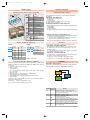
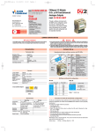
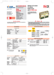
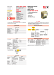
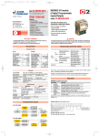
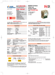
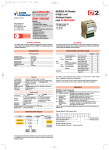
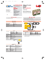
DO-32TS-uso-e
11-10-2011
16:32
Pagina 1
mod. IO-CB/DO-32TS-00
M.U. IO-CB/DO-32TS-2/07.07
Cod. J30-478-1ADO-32TS E
ISO9001 Certified
User
manual
Ascon Tecnologic S.r.l.
via Indipendenza 56,
27029 - Vigevano (PV), Italia
Tel.: +39 0381 69871,
Fax: +39 0381 698730
www.ascontecnologic.com
Contents
- Characteristics
- Functional Block Diagram
- PDOs used by the module
- Hardware Set-up
- Parameter configuration
- Commands
- Emergency messages
- Parameter Store/Restore
- Object Dictionary
E
CANopen I/O module
32 Digital
Outputs
mod. IO-CB/DO-32TS
32 digital outputs
Each of the output terminals can be
programmed as standard optoisolated
output with polarity control and filtering
APPLICABLE STANDARDS
WARNING
The DO-32TS module is suited for the CiA DS301 protocol [1] and implements the CiA
DS 401 standard Device Profile [2].
1) The product described in this manual should only be installed, operated and maintained by
qualified application programmers and software engineers who are familiar with automation
safety concepts and applicable national standards.
2) This product supports the Parameter defaults indicated by CiA standards, in addition, some parameters have a factory set (value present in the module when comes from the factory). The default
values can be loaded with the restore command, but after the restore, factory set values are lost.
Characteristics
Functional Block Diagram
Technical data
Change
polarity
Receive
Number of channels
Polarity (high side)
Output voltage
Output current
Total continuous output current max.
ON/OFF delay
32
Source (PNP)
24 Vdc (nominal)
0.5 A
16 A
<5 ms
Error
mode
Switch
if 0h
Block
filter
Device
failure
Error
value
PDOs used by the module
General
3 way isolation
Power supply
Power consuption
Overvoltage protection
Dimensions
Weight
Safety regulations
EN61010-1
CE marking
Channel to Channel
Channel to Logic
Logic to Serial Bus
Power Supply to Logic
24 Vdc; -15...+25%
3W
40 Vdc
L: 152; H: 110; W: 65
350 g
Isolation class II (50Vrms)
Installation cathegory II
Pollution degree 2
EN61131-2
No
800 Vp
800 Vp
800 Vp
3 way isolation
diagram
RPD0
RPDO 1
Fieldbus
Logic
Output
channels
1 - 16
Output
channels
17 - 32
800Vp
Environment
Mounting
Protection
Vibrations
(3 axes)
Shock (3 axes)
Operating
-10...+65°C
5...95% non condensing
Appropriate measures must
be taken against humidity
>85%
Vertical, free air
IP20
10...57Hz 0.0375mm
57...150Hz 0.5g
15g, 11ms half sine
Mapped objects
DigOutput 8_1
COBID: 200h+ NodeID
DigOutput 8_2
Transmission Type: 01h * DigOutput 8_3
DigOutput 8_4
Index
6200h
6200h
6200h
6200h
Sub-index
01h
02h
03h
04h
Note: * The Transmission Type is configurable:
01h is the factory set (value present in the modules when come from the factory);
FFh is the default value.
Power supply
Temperature
Relative
Humidity
Properties
Storage
-40...+85°C
5...95% non condensing
For a short period, slight
condensation may appear
on the housing
DO-32TS-uso-e
11-10-2011
16:32
Pagina 2
Hardware Set-up
Parameter configuration
Hexadecimal rotary switches, service and I/O LEDs
Configuring the Output Channels
Negative screw-driver
0.4 x 2.5 mm
Top view
Service Status
LEDs
ON
RUN Blinking
Single flash
OFF
ON
Single flash
ERR Double flash
Triple flash
OFF
ON
ST Blinking
Single flash
OFF
PWR ON
OFF
•
Hi
Lo
Fro
i
nt s
de
•
•
•
Meaning
Operational
Pre-operational (CANopen)
STOPPED
Device in RESET state
BUS OFF
Warning limit reached
Error Control Event
Sync Error (CANopen)
No error. Device working
DIAG Error
INIT and DIAG running
Baud rate setting
Module OK and ready
Module Power Supply ON
Module Power Supply OFF
I/O LEDs
Status Meaning
OUT 1...32 ON
Output active
OFF Output inactive
•
The Output functional block diagram is consistent with the standard profile
CiA DS401 [2].
Index 6200h – Write Output 8-bit
This object writes a group of 8 outputs:
1 = output active,
1 = output not active.
The output signalling from a CAN message is processed first.
Two preprocess items are performed:
• Polarisation Index 6202h – Polarity Output 8-bit
This object defines the polarity of a group of 8 output lines. Output polarity can be
inverted individually:
1 = output inverted,
0 = output not inverted.
If the object is not supported, the device behaves according to the default value.
• Masking Index 6208h – Filter Mask Output 8-bit
This object defines an additional output filter mask configurable for 4 outputs.
1 = output is set to the received output value
0 = do not care, the received output value is neglected for the corresponding output channel and the old output value is kept.
If the object is not supported, the device behaves according to the default value.
Bit Rate and Node ID configuration
Bit rate
In error mode, the outputs behave according to the following two entries:
Node ID
Baud rate
Lo switch
kbps
1
20
2
50
3
100
4
125
5
250
6*
500
7
800
8
1000
Bus length
m
2500
1000
500
500
250
100
50
25
Hi
Lo
switch switch
0
1
0
2
7
F
Error mode
Index 6206h – Error Mode Output 8-bit:
Valid ID Node
01h (address 1)
02h (address 2)
7Fh (address 127D) *
Notes: * Default value
This object indicates, whether an output is set to a pre-defined error value
(see 6207h object) in the event of an internal device failure or of a 'Stop
Remote Node' status.
1 = output value takes the pre-defined condition specified in object 6207h
0 = output value is kept if an error occurs
Index 6207h – Error Value Output 8-bit:
On condition that the corresponding Error Mode is active, device failures set
the outputs to the value configured by this object.
0 = Output is set to ‘0’ in case of fault, if object 6206h is enabled
1 = Output is set to ‘1’ in case of fault, if object 6206h is enabled.
Commands
Procedure for Node ID and Bit Rate configuration
The HI and LO hexadecimal rotary swithches set the module’s Bit Rate and CAN Node ID.
During the configuration, the module must be off line and the CAN bus must be physically
disconnected.
To configure the module, follow the procedure:
1 Turn the Power OFF
2 Set the HI switch to “F”
3 Select the desired Bit Rate value by setting the LO switch following the table
(e.g. “8” for 1 Mbps)
4 Turn the Power ON
5 Shift the HI switch to “E” (all the module service LEDs should flash)
6 Turn the Power OFF. Now configure Node ID
7 Set the HI and LO switches to the desired valid Node ID following the table
8 Turn the Power ON.
Alternatively, at step 7 set the value 00h. Then, at the next Power ON, the last valid stored
value will be resumed as Node ID.
Default values:
Bit Rate = 20 kbps, Node ID = 127D
Factory set values: Bit Rate = 500 kbps, Node ID = 127D
Index 200Ch – Operating mode:
the device has its own internal state machine. It is possible to move through this by
sending appropriate values to the Index 200Ch, following the table below.
4
Ready
1
3
2
Run
Error
3
Transition Operating
Storage
mode value
Init
At Power-Up, the Device is in the “ready” state.
Transition 1 is also executed if Index 200Ch - Operating
Mode contains the default value 1
1
01h
Operating mode “RUN” is activated
Return to the initialisation “ready” state.
The transition is performed:
2
00h
• following an operator’s command
The “error” state is automatically assigned by the device
3
FFh
(and the operating mode value is read only) when:
• an attempt is made to execute an unexpected command
This value causes an exit from the “error” state, after
4
00h
the error condition is acknowledged. The only transition
is to the “ready” state
DO-32TS-uso-e
11-10-2011
16:32
Pagina 3
Emergency messages
SDO Messages
The module automatically sends emergency messages including error codes. The
communication errors are descrided in CiA DS301 [1]. The error codes are expressed
as a DEVICE SPECIFIC ERROR type of code, one for each channel: 0xFF01 for channel
1 and 0xFF02 for channel 2. The codes indicating a specific condition are also inserted, following the table below:
Error code Error
0000000000 No error –This code is generated when exiting an error contidion,
to notify the end of one of the error states
0000000007 Error Wrong Command – An attempt to execute a command from an
illegal state
The entries of a device Object Dictionary are accessed trough SDO (Service Data Object)
messages. The basic SDO messages are as follows, as based on the Client – Server
request and response model:
0
Emergency 01h
Message
1
FFh
2
3
4
5
21h
00h
00h
00h
COB – ID = [entry 1014h] + NodeID
6
00h
7
0yh
Error code
Byte
Read request
Read response
Write request
Write response
0
40h
4xh *
22h
60h
2
3
4
5
6
Sub-Index
Reserved
COB – ID = 600h + NodeID
Index
Sub-Index
Data
COB – ID = 580h + NodeID
Index
Sub-Index
Data
COB – ID = 600h + NodeID
Index
Sub-Index
Reserved
COB – ID = 580h + NodeID
Index
* This code is type dependant.
Please refer to the CIA DS301 Profile for more details.
Reference documents
Parameter Store/Restore
This module allows parameters to be saved in a non volatile memory. In order to
avoid storing parameters by mistake, storage is only executed when a specific
signature is written to the appropriate subindex. The signature is “save”.
Similarly, the default values of parameters, according to the communication or
device profile, are restored. On receipt of the correct signature in the appropriate
subindex, the device restores the default parameters and then confirms the SDO
transmission. The signature is “load”.
The new configuration becomes active after a reset, i.e. after a “Power
OFF/Power ON cycle” or an NMT “Reset Node” message.
Byte
0
1
2
3
4
5
6
7
22h
10h
10h
73h
61h
76h
65h
01h
Store
Parameter
s
a
v
e
COB – ID = 600h + NodeID
22h
11h
10h
6Ch
6Fh
61h
64h
01h
Restore
Parameter
l
o
a
d
COB – ID = 600h + NodeID
1
List of CiA documents to which the user should refer
[1] CiA DS301 - CANopen Application Layer and Communication Profile
[2] CiA DS401 - CANopen Device Profile for generic I/O Modules
Accessories, Spare Parts and Warranty
Power Supply 45W 24Vdc 2A
Power Supply 120W 24Vdc 5A
Additional Terminal Block 2x11
Female Plug 11 Screw clamp
Female Plug 11 Spring clamp
RJ45 terminated cable 14cm
RJ45 terminated cable 22cm
CAN termination Adapter
AP-S2/AL-DR45-24
AP-S2/AL-DR120-24
AP-S2/TB-211-1
AP-S2/SPINA-V11
AP-S2/SPINA-M11
AP-S2/LOCAL-BUS76
AP-S2/LOCAL-BUS152
AP-S2/TERM-CAN
Warranty: 3 years excluding defects due to improper use
7
DO-32TS-uso-e
11-10-2011
16:32
Pagina 4
Object Dictionary (with default values)
A
In order to configure the module, it is necessary to connect it to a PC with the CAN interface and the superivisory software installed. The configuration can be obtained by
writing the desired values to the module’s variables listed in the Object Dictionary.
Object Dictionary structure
Index Sub
(hex) Index
1000
1001
1003
1005
1006
1007
1008
1009
100A
100C
100D
1010
00h
01h
1011
00h
01h
1014
1015
1017
1018
00h
01h
1200
00h
01h
02h
1400
00H
01h
02h
1600
00h
01h
02h
03h
04h
200C
3000
3001
Object
Name
VAR
VAR
ARRAY
VAR
VAR
VAR
VAR
VAR
VAR
VAR
VAR
ARRAY
VAR
VAR
ARRAY
Device Type
Error Register
Predefined error field
COB-ID SYNC
Communication cycle period
Synchrounous window length
Manufacturer Device Name
Manufacturer Hardware Version
Manufacturer Software Version
Guard Time
Life Time Factor
Store Parameters
Largest subindex supported
Save all parameters
Restore Default Parameters
VAR
VAR
VAR
VAR
VAR
RECORD
VAR
VAR
RECORD
VAR
VAR
VAR
RECORD
VAR
VAR
VAR
RECORD
VAR
VAR
VAR
VAR
VAR
VAR
VAR
VAR
Largest subindex supported
Restore all default parameters
COB-ID EMCY
Inhibit Time EMCY
Producer heartbeat time
Identity Object
Number of entries
Vendor ID
Server SDO Parameters
Number of entries
COB-ID Client -> Server
COB-ID Server -> Client
1st Receive PDO Comm Param.
Largest subindex supported
COB-ID used
Transmission type
1st Receive PDO Mapping
No. of mapped application obj.
DigOutput8_1
DigOutput8_2
DigOutput8_3
DigOutput8_4
Operating Mode
Node Address
Node Baudrate
Default
[hex]
00020191
00
00000000
00000080
00000000
00000000
“32TS”
“1.00”
“1.00”
0000
00
01
03
01
01
80+NodeID
0000
0000
01
000000E9
Type
UNSIGNED32
UNSIGNED8
UNSIGNED32
UNSIGNED32
UNSIGNED32
UNSIGNED32
Vis-String
Vis-String
Vis-String
UNSIGNED16
UNSIGNED8
UNSIGNED32
UNSIGNED8
UNSIGNED32
UNSIGNED32
UNSIGNED8
UNSIGNED32
UNSIGNED32
UNSIGNED16
UNSIGNED16
Identity (23h)
UNSIGNED8
UNSIGNED32
02
UNSIGNED8
600+NodeID UNSIGNED32
580+NodeID UNSIGNED32
PDO CommPar (20h)
02
UNSIGNED8
200+NodeID UNSIGNED32
FF *
UNSIGNED8
PDO Mapping (21h)
04
UNSIGNED8
62000108 UNSIGNED32
62000208 UNSIGNED32
62000308 UNSIGNED32
62000408 UNSIGNED32
01
UNSIGNED8
7F
UNSIGNED8
06
UNSIGNED8
Acc. MO
Attr.
RO
M
RO
M
RO
O
RW
O
RW
O
RW
O
const O
const O
const O
RW
O
RW
O
O
RO
RW
RW
O
RO
RW
RW
RW
RW
O
O
O
M
Index Sub
(hex) Index
6200
00h
01h
02h
03h
04h
6202
00h
01h
02h
03h
04h
6206
00h
01h
02h
03h
04h
6207
00h
01h
02h
03h
04h
RO
RO
RO
RO
RO
O
6208
00h
01h
02h
03h
04h
M
RO
RW
RW
Object Name
ARRAY
VAR
VAR
VAR
VAR
VAR
ARRAY
VAR
VAR
VAR
VAR
VAR
ARRAY
VAR
VAR
Write Output 8 - bit
Number of entries
DigOutput 8_1
DigOutput 8_2
DigOutput 8_3
DigOutput 8_4
Polarity Output 8 - bit
Number of entries
Polarity 8_1
Polarity 8_2
Polarity 8_3
Polarity 8_4
Error Mode Output 8 - bit
Number of entries
ErrorMode 8_1
VAR
VAR
VAR
ARRAY
VAR
VAR
VAR
VAR
VAR
ARRAY
VAR
VAR
VAR
VAR
VAR
ErrorMode 8_2
ErrorMode 8_3
ErrorMode 8_4
Error Value Output 8 - bit
Number of entries
ErrorValue 8_1
ErrorValue 8_2
ErrorValue 8_3
ErrorValue 8_4
Filter Mask Output 8 - bit
Number of entries
FilterMask 8_1
FilterMask 8_2
FilterMask 8_3
FilterMask 8_4
Default
[hex]
04
00
00
00
00
04
00
00
00
00
04
FF
FF
FF
FF
04
00
00
00
00
04
FF
FF
FF
FF
Type
UNSIGNED8
UNSIGNED8
UNSIGNED8
UNSIGNED8
UNSIGNED8
UNSIGNED8
UNSIGNED8
UNSIGNED8
UNSIGNED8
UNSIGNED8
UNSIGNED8
UNSIGNED8
UNSIGNED8
UNSIGNED8
UNSIGNED8
UNSIGNED8
UNSIGNED8
UNSIGNED8
UNSIGNED8
UNSIGNED8
UNSIGNED8
UNSIGNED8
UNSIGNED8
UNSIGNED8
UNSIGNED8
UNSIGNED8
UNSIGNED8
UNSIGNED8
UNSIGNED8
UNSIGNED8
M
RO
RO
RO
RO
RO
RW
RO
RO
O
O
O
*
The factory set (value present in the modules when new) for the
transmission type is: 01h.
Acc. MO
Attr.
M
RO
RW
RW
RW
RW
O
RO
RW
RW
RW
RW
O
RO
RW
RW
RW
RW
O
RO
RW
RW
RW
RW
O
RO
RW
RW
RW
RW