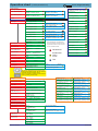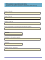
1
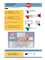
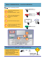
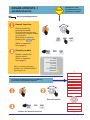
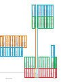
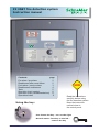
FX 3NET fire detection system
Instruction manual
Contents:
page
Fire alarm / pre-alarm
Disablement after reset failure
Fault alarm / service alarm
Disablement/ enablement
Tests
Operation chart (seeing)
Operation chart (visible/standalone)
Operational data
Using the key:
2
2
3
4
5
6
8
11
NOTE!
Read the instructions
carefully before using
the fire detection system.
Keep the instruction
manual close to
the control panel.
Use: Insert the key - turn to the right.
Normal status: Turn key to the left remove the key
66571774GB0
46-2011
FIRE ALARM/
pre-alarm
Only for firemen!
Key in operating position!
Buzzer silence
Silence the panel buzzer by
pressing the
“BUZZER SILENCE” - button
Silence /
Re-sound
Silence the alarm devices by
pressing the
“SILENCE/RE-SOUND" - button
More alarms
Scroll fire alarm objects
or
Press for as long as the signal
is heard, whereupon the
system returns to normal state.
Reset
Fire
Prealarm
Extinguisher activated
Buzzer silence
Smoke vents activated
Fire routing activated
Silence /
Re-sound
More alarms
Reset
EN 54-2
Fault
Maintenance
Fault routing activated
SS 3654
Alarm devices deactivated
Evacuation
Technical alarm
Test
Day mode
System fault
Fire routing
Alarm devices
Fire outputs delayed
Disablement
EN 54-4
Power supply
Battery use
Disable /
Enable
Test
1
2
Disablement of addresses, after reset to normal state has failed:
Press the "DISABLE"
button when the address is
shown on the display.
66571774GB0
Disable /
Enable
2
Test
46-2011
FAULT INDICATION / service indication
Key in operating position!
Buzzer silence
Silence the panel buzzer by
pressing the
“BUZZER SILENCE” - button
Silence /
Re-sound
Silence the alarm devices by
pressing the "SILENCE" button
More alarms
Scroll fault indication objects.
or
Press for as long as the signal is
heard, whereupon the
system returns to normal state.
Reset
Fire
Prealarm
Extinguisher activated
Buzzer silence
Smoke vents activated
Fire routing activated
Silence /
Re-sound
More alarms
Reset
EN 54-2
SS 3654
Power supply
Battery use
Fault
Maintenance
Fault routing activated
Alarm devices deactivated
Evacuation
Technical alarm
Test
Day mode
System fault
Fire routing
Alarm devices
Fire outputs delayed
Disablement
EN 54-4
Disable /
Enable
Test
1
2
Disablement of address or fault monitoring:
Press the "DISABLE"-button
when the fault or service indication
is shown on the display.
Note! Disablement can not be
done in all situations.
Refer to operation chart page 8
66571774GB0
NOTE!
Disable /
Enable
Test
If a fault occurs
always contact
your supplier's service!
3
46-2011
DISABLEMENTS /
enablements
NOTE!
Remember that
disablements may
prevent an alarm!
Key in operating position!
Search function
kli
Enter the menu by
pressing the wheel.
Go to the desired point by
scrolling the selection wheel
on the menu.
Move back in menu by
pressing the
key.
ck
Disable /
Enable
Test
(Refer to operation
chart page 6)
Disable/enable
Disable /
Enable
Disable / enable the
desired object.
(Refer to operation
chart page 8)
Test
Fault
Maintenance
Fault routing activated
System fault
Fire routing
When something has been
disabled: the "DISABLEMENT"
signal light is lit.
Alarm devices
Fire outputs delayed
Disablement
input interfaces
output interfaces
Scrolling disablements and enabling
from the disablement register
active disablements
active prealarms
active faults
kl
ic k
active technical alarms
active tests
event register
Search function
printings
Disable /
Enable
current access level: X
Test
system test
Enable the desired function
66571774GB0
4
46-2011
TESTS
Key in operating position!
kli
Search function
ck
Enter the menu by
pressing the wheel.
Go to the desired point by
scrolling the selection wheel
on the menu.
(Refer to operation
chart page 8)
Start test
Disable /
Enable
Test
Technical alarm
Test
Day mode
follow the advice on
the display
Finish test
Disable /
Enable
Technical alarm
Test
Day mode
Test
loops / address points
Monthly test
Test of alarm transmission
to regional alarm center.
/FX system test
Inform the regional alarm
center of the test to be
performed.
After the test, check with the
regional alarm center that
the information was received.
controls
monitorings
Technical alarm
Test
Day mode
input interfaces
output interfaces
active disablements
active prealarms
Disable /
Enable
Test
active faults
active technical alarms
active tests
event register
printings
Display test
current access level: X
Disable /
Enable
system test
Test
alarm transmission test
set time
hh:mm dd.mm.yyyy
66571774GB0
5
46-2011
66571774GB0
6
46-2011
controls
loops / address points
monitorings
Test
Enablement/
Verify/
Finish
Disablement
The disablement, enablement and test markers
mean that the respective function can be used in
the marked context.
The chart is activated by
turning the key and
pressing the selection
wheel. You can scroll up
and down using the
selection wheel.
Move to next level by
pressing the wheel.Move
back by pressing the
arrow key.
fire panels
zones / address points
loops / address points
Activate submenu by pressing
wheel ->
loop xx
xxx address points
controls
loop xx addresses
Address xx.xxx
Select zone number 0001
zones / address points
(seeing)
zone xxxx
xx address points
change primary/
secondary language
Operation chart
power inputs monitor
extinguisher monitor
fault routing monitor
fire routing monitor
earth leagage monitor
power outputs monitor
alarm devices monitor
power supply monitor
disablement outputs
maintenance outputs
fault warning device control
fault outputs
fault routing control
technical alarm outputs
prealarm outputs
fire routing activated led outputs
delay T2 outputs
delayed fire outputs
extinguisher control
fire door control
fire outputs
alarm devices control
fire routing control
normal fire routing func.
(access level 3)
zone xxxx
xx address points
loop xx
xxx address points
all controls enabled
to disable all controls press "disable"
zone xxxx addresses
address xx.xxx
Fire routing monitor
fire routing fault input UNIT X IN X
Alarm devices monitor
fault routing fault input UNIT X IN X
Extinguisher monitor
extinguisher fault input UNIT X IN X
Alarm devices monitor
UNIT X alarm devices line x mon.
Power outputs monitor
UNIT X power output PO X mon.
zone xxxx addresses
Address xx.xxx
loop xx addresses
Address xx.xxx
Don't forget the key!
disablement outputs
maintenance outputs
fault warning device control
fault outputs
fault routing control
technical alarm outputs
prealarm outputs
fire routing activated led outputs
delay T2 outputs
delayed fire outputs
extinguisher control
fire door control
fire outputs
alarm devices control
fire routing control
normal fire routing func.
all controls enabled
to disable all controls press "disable"
(access level 3)
66571774GB0
7
46-2011
alarm transmission test
set time: hh:mm
dd:mm:yyyy
software versions
-------------------------------------MC
v x.xx dd.mm.yyyy
alarm transmission
test
set time hh:mm
dd.mm.yyyy
software versions
change language
(access level 3)
(access level 3)
analyze loop
communications
(access level 3) press “enable”
loop xx
Esmi / Intellia
xxx address points
loop xx
Esmi / SystemSensor
xxx address points
“language"
press: "enable”
system test
system test
Main menu
report dirty detectors
change to access level 3
current access level: X
printings
event register
FX fire panel PP
"point”
active tests
FX fire panel PP
"point”
active faults
FX fire panel PP
"point”
FX fire panel PP
Zone xxxx Address xx.xxx
active prealarms
active technical alarms
FX fire panel PP
"point" disabled
active disablements
software versions
------------------------------------------MC
v x.xx dd.mm.yyyy
Connections
xx/xx
connection to panel PP
Not in use
press: "enable”
Printer (ASCII)
press: "enable”
INFO protocol
press: "enable”
Loop communications
address point xx.xxx polled xxx times
Loop communications
address point xx.xxx polled xxx times
RS-232 usage
(access level 3)
connections
software versions
fire alarm conditions count xxx
to clear the counter press wheel
alarm counter
(access level 4)
alarm transmission test
UNIT X IN X
"type"
UNIT X output X
"type"
Disablement
xxx/xxx
"point" disabled
Fire
xxx/xxx
Zone xxxx Address xx.xxx
Prealarm
xxx/xxx
Zone xxxx Address xx.xxx
Technical alarm
xxx/xxx
"point”
Fault
xxx/xxx
"point”
Test
xxx/xxx
"point”
alarm transmission test
active tests
active faults
active technical alarms
active prealarms
active fires
active disablements
output interfaces
input interfaces
set events xxx-xxx
start printing by pressing enable
set disablements xxx-xxx
start printing by pressing enable
set test alarms xxx-xxx
start printing by pressing enable
set technical alarms xxx-xxx
start printing by pressing enable
set prealarms xxx-xxx
start printing by pressing enable
set fires xxx-xxx
start printing by pressing enable
set faults xxx-xxx
start printing by pressing enable
set loops xx-xx
start printing by pressing enable
set zones / addresses xxxx-xxxx
start printing by pressing enable
clear by pressing "enable”
Event register clearing
(access level 3)
events xxx-xxx ->
start printing by pressing enable
disablements xxx-xxx ->
start printing by pressing enable
test alarms xxx-xxx ->
start printing by pressing enable
technical alarms xxx-xxx ->
start printing by pressing enable
prealarms xxx-xxx ->
start printing by pressing enable
fires xxx-xxx ->
start printing by pressing enable
faults xxx-xxx ->
start printing by pressing enable
loops xx-xx ->
start printing by pressing enable
zones / addresses xxxx-xxxx ->
start printing by pressing enable
event date HH:MM
DD.MM.YYYY
Event register browsing
Operation chart
Don't forget the key!
(visible/standalone)
change primary/
secondary language
all controls enabled
to disable all controls press "disable"
zones / address points
loops / address points
(access level 3)
zone xxxx
enabled xx address points
zone xxxx addresses
xx/xx
Address xx.xxx enabled
normal fire routing func.
loop xx
enabled xxx address points
loop xx addresses
xx/xx
Address xx.xxx enabled
fire routing control
controls
alarm devices control
monitorings
fire outputs
power supply monitor
Alarm devices monitor
xx/xx
UNIT X alarm devices line x mon.
Power outputs monitor
xx/xx
UNIT X power output PO X mon.
alarm devices monitor
power outputs monitor
fire door control
extinguisher control
delayed fire outputs
earth leagage monitor
Fire routing monitor
xx/xx
fire routing fault input UNIT X IN X
Alarm devices monitor
xx/xx
fault routing fault input UNIT X IN X
Extinguisher monitor
xx/xx
extinguisher fault input UNIT X IN X
fire routing monitor
fault routing monitor
extinguisher monitor
delay T2 outputs
fire routing activated led outputs
prealarm outputs
technical alarm outputs
power inputs monitor
The disablement, enablement
and test markers mean that the
respective function can be used
in the marked context.
input interfaces
UNIT X IN X
"type”
xx/xx
output interfaces
UNIT X output X
"type"
active disablements
Disablement
"point"
active prealarms
Prealarm
Zone xxxx
active faults
Fault
"point”
active technical alarms
Technical alarm
"point”
active tests
Test
"point”
event register
Event register browsing
Event
xxx/xxx
event date HH:MM DD.MM.YYYY
Event register clearing
clear by pressing "enable”
xx/xx
fault routing control
fault outputs
fault warning device control
xxx/xxx
Disablement
xxx/xxx
Address xx.xxx
Enablement/
Verify/
Finish
xxx/xxx
maintenance outputs
disablement outputs
xxx/xxx
Test
xxx/xxx
(access level 3)
The chart is activated by turning the key and
pressing the selection wheel. You can scroll up
and down using the selection wheel.
Move to next level by pressing the wheel.Move
back by pressing the arrow key.
events xxx-xxx ->
start printing by pressing enable
disablements xxx-xxx ->
start printing by pressing enable
test alarms xxx-xxx ->
start printing by pressing enable
technical alarms xxx-xxx ->
start printing by pressing enable
prealarms xxx-xxx ->
start printing by pressing enable
fires xxx-xxx ->
start printing by pressing enable
faults xxx-xxx ->
start printing by pressing enable
loops xx-xx ->
start printing by pressing enable
zones / addresses xxxx-xxxx ->
start printing by pressing enable
printings
current access level: X
change to access level 3: 0000
system test
system test
alarm transmission test
alarm transmission test
set time
hh:mm dd.mm.yyyy
set time: hh:mm dd:mm:yyyy
alarm counter
software versions
connections
fire alarm conditions count xxx
to clear the counter press wheel
(access level 4)
software versions
--------------------------------------MC
v x.xx dd.mm.yyyy
Connections
xx/xx
connection to panel PP
set events xxx-xxx
start printing by pressing enable
set disablements xxx-xxx
start printing by pressing enable
set test alarms xxx-xxx
start printing by pressing enable
set technical alarms xxx-xxx
start printing by pressing enable
set prealarms xxx-xxx
start printing by pressing enable
set fires xxx-xxx
start printing by pressing enable
set faults xxx-xxx
start printing by pressing enable
set loops xx-xx
start printing by pressing enable
set zones / addresses xxxx-xxxx
start printing by pressing enable
report dirty detectors
(access level 3) press: 'enable’
analyze loop communications loop xx
Esmi / Intellia
(access level 3)
xxx address points
loop xx
Esmi / SystemSensor
xxx address points
change language
“language"
press: "enable”
RS-232 usage
Not in use
press: "enable"
Printer (ASCII)
press: "enable”
INFO protocol
press: "enable"
(access level 3)
(access level 3)
66571774GB0
Loop communications
address point xx.xxx polled xxx times
Loop communications
address point xx.xxx polled xxx times
8
46-2011
66571774GB0
9
46-2011
66571774GB0
10
46-2011
FX system operational data
(filled in by the system operator in connection with start-up)
Owner of the site
Name of the site
Address of the site
Person responsible for operating the fire detection system
Telephone
Substitute for the system operator
Telephone
Supplier's service, telephone
66571774GB0
11
46-2011
Manufacturer:
Pelco Finland Oy
P.O.Box 415, FIN-02601 Espoo
www.pelco.fi
66571774GB0
46-2011