1
1. Short description
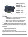
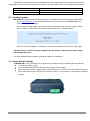
TCW122B-CM is an Ethernet controller, based on TCW122 hardware. It has 2 digital and 2 analog
inputs, 1-Wire interface for up to 2 temperature/humidity sensors and 2 relays with NO/NC contacts.
The relays can be activated either remotely (WEB, SNMP etc.) or locally - from status of monitored
parameter (temperature, humidity, analog voltage and dry contact). Only one parameter can manage
the relay at the same time, but for every parameter can be sent e-mail/SNMP trap for alert conditions.
TCW122B-CM is suitable for environmental monitoring and local control of heater/coolers,
industrial and building automation, data acquisition systems, general remote control and monitoring.
2. Features
10 Mb Ethernet connectivity;
Password protected, web based configuration and control;
2 digital inputs with " dry contact" and "logic level" modes;
2 analog inputs with 0 to 60VDC range;
2 relays with NO and NC contacts;
Long 1-Wire support for up to 2 temperature (TST1XX) or temperature/humidity (TSH2xx)
sensors;
SNMP v.1 support;
SNMP traps and/or e-mail sending for alert conditions;
SMTP with authentication (SSL is not supported);
HTTP and SNMP port changing;
HTTP and XML API commands;
Remote firmware update.
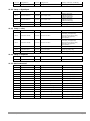
3. Technical parameters
Supply voltage, VDC
Maximum current consumption (with both relays ON), mA
Weight, g
Dimensions, mm
Operating temperature, °C
Maximum humidity in 0 to 31°C range, %RH
Maximum humidity at 40°C (linear slope between 31-40°C), %RH
Minimum high level input voltage for digital inputs, VDC
Maximum low level input voltage for digital inputs, VDC
Maximum input voltage for digital inputs, VDC
Supply voltage for 1-wire bus (VDD), VDC
Maximum output current for 1-wire bus (VDD), A
Analog inputs range, VDC
Maximum switchable current for relay contacts, А
Maximum switchable voltage for relay contacts, VAC/VDC
TCW122B-CM_R3 - June 2014
12±2
200
110
107 x 72 x 32
0 to +40
80
50
+2.5
+0.8
+5.5
5.3 ± 0.2
0.2
0 to +60
3
30/24
Page 2
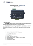
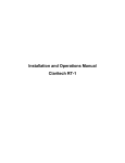
4. Connectors
Inputs and outputs locations are shown below:
Connector 1 – Power - central positive
Connector 2, Pin1 - Digital input 1 (Din1)*
Connector 2, Pin2 - Digital input 2 (Din2)*
Connector 2, Pin3 - Ground
Connector 2, Pin4 - Analog input 1 (Ain1)
Connector 2, Pin5 - Analog input 2 (Ain2)
Connector 2, Pin6 - Ground
Connector 2, Pin7 – 1-Wire data
Connector 2, Pin8 – 1-Wire power supply
Connector 3 – Ethernet - RJ45
Connector 4, Pin1 – NC Relay1
Connector 4, Pin2 – COM Relay1
Connector 4, Pin3 – NO Relay1
Connector 5, Pin1 – NC Relay2
Connector 5, Pin1 – COM Relay2
Connector 5, Pin1 – NO Relay2
* Operating mode is selected by jumper DI1/DI2 - closed for “dry contact” and open for “logic
level”. By default jumpers are closed.
5. LED indicators
The following indicators show the status of the controller:
Relay1/Relay2 (green) – these LEDs are illuminated whenever the corresponding relay is
activated (the NO contact is closed and the NC contact is open);
Sts (red) – flashes when the main program of controller is executed;
Log (yellow) – indicates that somebody is logged via WEB interface;
Link (green) – on Connector 3, indicates that the device is connected to the network;
Act (yellow) – on Connector 3, flashes when activity is detected on the network.
6. Powering
TCW122B-CM is designed to be supplied by adapter SYS1421-0612-W2E or similar, intended for
use in the conditions of overvoltage category II, and priorly assessed for compliance with safety
requirements. The power supply equipment shall be resistant to short circuit and overload in secondary
circuit.
When in use do not position the equipment so that it is difficult to disconnect the device from
the power supply.
7. Installation
This device must be installed by qualified personnel.
This device must not be installed directly outdoors.
Installation consists of mounting the device, connecting to an IP network, connecting inputs and
outputs, providing power and configuring via a web browser.
TCW122B-CM can be wall or flat, not flammable surface mounted, in a clean and dry location
room. Ventilation is recommended for installations where ambient air temperature is expected to be
high.
TCW122B-CM_R3 - June 2014
Page 3
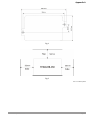
Mount the device to a wall by using two plastic dowels 8x60mm (example Würth GmbH 0912
802 002) and two dowel screws 6x70mm (example Würth GmbH 0157 06 70). Attach the screws to the
surface vertically. See Appendix-A, fig. 1 for mechanical details.
Maintain spacing from adjacent equipment. Allow 50 mm of space on all sides, as shown on fig.2
in Appendix A, this provides ventilation and electrical isolation.
8. Configuration
Please follow the steps below for proper installation :
1. Mount the controller in a dry and ventilated place.
2. Connect the Ethernet port to a 10/100MB Ethernet network. For direct connection to a PC use
a “crossover” cable.
3. Connect the I/O pins of the controller according to the required application.
4. Connect the power supply.
If the red LED (STS) blinks, the main program of controller is executed. By default TCW122B-CM
comes with the following network settings:
IP address: 192.168.1.2, Subnet Mask: 255.255.255.0, Default Gateway: 192.168.1.1
Communication with TCW122B-CM can be established by assigning a temporary IP address to the
computer. This address should be in the same network (for example 192.168.1.3). To get access to the web
interface, you should type http://192.168.1.2 into the browser.
If the network settings are correct, the “Login” page will appear.
The web based interface allows configuration, monitoring and control. Recommended browser is
Internet Explorer at 1024x768 resolutions.
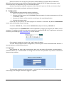
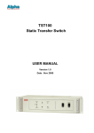
8.1 Login page
After opening the Login page, authorization data must be entered (by default username=admin ,
password=admin). It is recommended to change the username and password to prevent unauthorized
access to the controller.
The controller supports one active session – only one user can operate the device. If another user
tries to login, the message “Someone’s logged in” appears:
TCW122B-CM_R3 - June 2014
Page 4
The active session will be terminated automatically, if the current user stays inactive for 2 minutes.
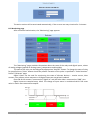
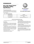
8.2 Monitoring page
After successful authorization, the “Monitoring” page appears:
The “Monitoring” page provides information about the state of the relays and digital inputs, values
of analog voltages (applied on analog inputs), temperature and humidity.
The state of the relay can be changed by appropriate “ON/OFF” button. To change the state of relay
for specified time “Pulse” button should be pressed. Duration of the pulse is specified in “Pulse Duration”
field of “I/O Setup” page.
Digital inputs can be used for monitoring the state of discrete devices – motion sensor, door
contact, relay contact, alarm output etc. All digital inputs are not galvanic isolated.
One side of the contact is connected to “Digital In” and the other side is connected to “GND” pins.
Digital inputs are sampled every 10mS. The change of input status is considered valid if the same
value is read in two consecutive samples.
TCW122B-CM_R3 - June 2014
Page 5
8.3 Network Setup page
The Network parameters are set on this page. The following parameters can be changed:
IP configuration – IP Address can be static or dynamic (DHCP server should be present in the
network);
IP address, Subnet mask , Default gateway – these fields are active if IP address is static;
DNS – these fields is mandatory, if domain names are used instead of IP addresses. By default
DNS has the same Ip address as Default gateway;
Time Server and Time Zone – these fields are not mandatory, they are used when e-mail must
be sent;
Host Name – up to 16 symbols, it appears as a “Subject” in sent e-mails;
MAC – device MAC address.
The good practice is to change the default IP address of controller immediately after first power-on.
This will avoid collisions if many devices are used in the same network. It may be necessary to clear the arp
cache, each time you connect a new device to the network. This is done by typing arp -d in the command
prompt window of computer.
To use e-mail alerts following fields should be completed:
Mail server type – either “custom” or “tcw gateway”.
“Custom” – public or private mail server without SSL should be used.
Important! TCW122B-CM does not support Secure Socket Layer (SSL);
“Tcw gateway” - dedicated mail server is used.
Important! The service is free and not guaranteed.
Mail server [IP:port] – domain or IP address and port of SMTP mail server;
Sender E-mail – sender e-mail;
Username and Password – authentication details for mail server;
Recipient e-mail.
TCW122B-CM_R3 - June 2014
Page 6
Username and password for WEB access to TCW122B-CM can be changed in the Web Access
section. Setting the authentication to “disabled” will provide access to monitoring page without entering
user name and password. The HTTP port can be changed also in this section.
XML/HTTP API section controls the access to XML file and HTTP commands. Detailed information
can be found in chapter “XML and HTTP API commands”.
8.4 SNMP Setup page
TCW122B-CM supports SNMP v.1. This enables the device to be part of large monitoring and
control networks. The possible settings for “SNMP” section are:
SNMP Configuration – enable/disable SNMP;
SNMP Port – allows standard port changing;
Write/Read community – performs client authentication;
SNMP Traps – enable/disable SNMP trap messages;
IP address – IP address of the receiving host;
Community string – performs client authentication;
Trap Interval - time interval in seconds for SNMP trap messages;
Max. Traps number – maximum number of SNMP trap messages sent, if trap condition is
present.
SNMP traps are sent if:
event occurs (status change) on Digital Input 1 or Digital Input 2;
measured voltage on Analog Input 1 or Analog Input 2 goes outside the range;
measured temperature goes outside the range;
measured humidity goes outside the range;
restart condition.
TCW122B-CM_R3 - June 2014
Page 7
8.5 I/O setup page
I/O settings can be made here. For temperature, humidity and analog value MIN, MAX and
HISTERESYS values can be set. These values define the thresholds for all monitored parameters.
When the measured value goes out of range SNMP trap or e-mail (if enabled) will be sent. Leaving
range is considered when the parameter goes lower than MIN values or higher than MAX. Coming back in
the range is considered when the parameter goes higher than (MIN + HISTERESYS) or lower than (MAX –
HISTERESYS).
TCW122B-CM_R3 - June 2014
Page 8
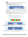
Example:
TCW122B-CM, TST100 and appropriate heater are used to control the room temperature.
The wanted minimum temperature is 19°C. The initial temperature is 17°C.
TST100 is assigned on the first position for 1-Wire sensors.
For Relay1 local activation from Sensor1 is set.
Following parameters are set for Sensor1: Min=19, Max=100 and Hys=0.5.
When the controller is switched on, Relay1 is immediately activated because the
monitored temperature is out of range. This switches the heater on. The temperature is
going higher.
When temperature reaches 19.5°C (19.0 + 0.5) it goes in range (trigger condition) and
Relay1 is deactivated. The heater is switched off.
The temperature falls and when it reached 19°C it goes out of range (trigger and alert
conditions). The relay is activated (heater is switched on) and e-mail is sent.
For digital inputs, conditional e-mail sending can be arranged by following part of the page:
Relays can be activated automatically depends of value of monitored parameter (humidity,
temperature, analog voltage and changes on digital inputs) or manually. Only one parameter can be
assigned for relay activation, at the same time:
When manual activation is selected, “Pulse” and “ON/OFF” buttons on “Monitoring” page are
active. The duration of pulse for relay activation can be set from 1 to 253 seconds.
TCW122B-CM_R3 - June 2014
Page 9
For every sensor, analog input, digital input and relay description with length of 11 characters can
be set.
Temperature units can be changed between Fahrenheit and Celsius.
Automatic monitoring page refresh interval can be set from 1 to 253 second. If 0 is chosen – the
monitoring page will not refresh automatically.
8.6 Update page
For details see chapter - 16. Firmware update.
9. Application examples
The examples and diagrams in this manual are included solely for illustrative purposes. Because
of the many variables and requirements associated with any particular installation, Teracom Ltd. cannot
assume responsibility or liability for actual use based on the examples and diagrams.
9.1.
Temperature and humidity control
TCW122B-CM supports 1-Wire temperature and humidity sensors, which makes it suitable for
use in heating and cooling systems.
TCW122B-CM_R3 - June 2014
Page 10
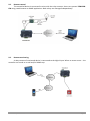
9.2.
Remote control
The controlled device is connected in series with the relay contacts. Users can operate TCW122BCM using a web browser or SNMP application. Both relays are managed independently.
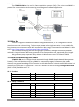
9.3.
Remote monitoring
A relay contact of monitored device is connected to the digital input. When an event occurs – the
controller can sends an e-mail and/or SNMP trap.
TCW122B-CM_R3 - June 2014
Page 11
9.4.
Data acquisition
The TCW122B-CM can be used in Data Acquisition Systems (DAQ). The device uses SNMP v.1
protocol for communication with monitoring and management software applications.
10.1-Wire Bus
1-Wire is a registered trademark of Maxim Integrated Products, Inc. It is designed to connect
several sensors over a short wiring. The bus carries power and a single data wire. It is not suitable for
long distances or environments with EMC interference. We strongly recommend to read Maxim’s 1-Wire
tips at http://www.maxim-ic.com/app-notes/index.mvp/id/148.
We recommend keeping the total wiring length under 60m, although functionality has been
achieved in longer distance. We cannot guarantee error-free operation over mentioned wiring length.
We guarantee proper operation only with our 1-Wire sensors series TST1XX and TSH2XX.
11.Control and monitoring using SNMP
TCW122B-CM can be configured and monitored through SNMP (Simple Network Management
Protocol). This could be done using every SNMP v.1 compatible program. Parameters that can be
changed, are grouped according to their functions in the tables below. To obtain a valid OID number it is
necessary to replace the “x” symbol with ”1.3.6.1.4.1.38783”. To save the changes configurationSaved
(OID x.3.13.0) should be set to "1".
11.1. Product
OID
Name
Access
Description
Syntax
x.1.1.0
name
read-only
Device name
String
x.1.2.0
version
read-only
Firmware version
String
x.1.3.0
date
read-only
Release date
String
Description
Syntax
11.2. Setup -> network
OID
Name
Access
x.2.1.1.0
deviceIPAddress
read-write Device IP address
IpAddress
x.2.1.2.0
subnetMask
read-write Subnet Mask
IpAddress
x.2.1.3.0
gateway
read-write Gateway
IpAddress
x.2.1.4.0
deviceMACAddress
read-write Device MAC Address
OCTET STRING (SIZE(6))
x.2.1.5.0
dhcpConfig
read-write DHCP configuration ON/OFF
INTEGER { off(0), on(1) }
x.2.1.6.0
dns
read-write Domain Name Server address
IpAddress
TCW122B-CM_R3 - June 2014
Page 12
x.2.1.7.0
Hostname
read-write Device hostname
String (SIZE (0..38))
Syntax
11.3. Setup -> snmpSetup
OID
Name
Access
Description
x.2.4.1.0
snmpConfiguration
read-write SNMP Configuration
INTEGER { disabled(0), enabled(1) }
x.2.4.2.0
trapEnabled
read-write TRAP messages ENABLED/DISABLED
INTEGER { no(0), yes(1) }
x.2.4.3.0
trapReceiverIPAddress
read-write TRAP receiver IP address
IpAddress
x.2.4.4.0
trapCommunity
read-write TRAP community
String (SIZE (0..13))
x.2.4.5.0
trapInterval
read-write TRAP messages interval
INTEGER (1..253)
x.2.4.6.0
maxNumberOfTraps
read-write Maximum number SNMP traps
INTEGER (1..253)
11.4. Setup -> oneWireSensor1 -> temperature1
OID
Name
Access
Description
Syntax
x.2.5.1.1.0
temperature1Min
read-write Temperature1 range (min. value)
INTEGER (-400..1250)
x.2.5.1.2.0
temperature1Max
read-write Temperature1 range (max. value)
INTEGER (-400..1250)
x.2.5.1.3.0
temperature1Hyst
read-write Hysteresis
INTEGER (0..1250)
x.2.5.1.4.0
temperature1Action
read-write Temperature1 action
INTEGER { noAction(0), sendMail(1) }
11.5. Setup -> oneWireSensor1 -> humidity1
OID
Name
Access
Description
Syntax
x.2.5.2.1.0
humidity1Min
read-write Humidity1 range (min. value)
INTEGER (0..1000)
x.2.5.2.2.0
humidity1Max
read-write Humidity1 range (max. value)
INTEGER (0..1000)
x.2.5.2.3.0
humidity1Hyst
read-write Hysteresis
INTEGER (0..1000)
x.2.5.2.4.0
humidity1Action
read-write Temperature1 action
INTEGER { noAction(0), sendMail(1) }
11.6. Setup -> oneWireSensor2 -> temperature2
OID
Name
Access
Description
Syntax
x.2.6.1.1.0
temperature2Min
read-write Temperature2 range (min. value)
INTEGER (-400..1250)
x.2.6.1.2.0
temperature2Max
read-write Temperature2 range (max. value)
INTEGER (-400..1250)
x.2.6.1.3.0
temperature2Hyst
read-write Hysteresis
INTEGER (0..1250)
x.2.6.1.4.0
temperature2Action
read-write Temperature2 action
INTEGER { noAction(0), sendMail(1) }
11.7. Setup -> oneWireSensor2 -> humidity2
11.8.
11.9.
OID
Name
Access
Description
Syntax
x.2.6.2.1.0
humidity2Min
read-write Humidity2 range (min. value)
INTEGER (0..1000)
x.2.6.2.2.0
humidity2Max
read-write Humidity2 range (max. value)
INTEGER (0..1000)
x.2.6.2.3.0
humidity2Hyst
read-write Hysteresis
INTEGER (0..1000)
x.2.6.2.4.0
humidity2Action
read-write Temperature2 action
INTEGER { noAction(0), sendMail(1) }
Setup -> analogInput -> input1
OID
Name
Access
Description
Syntax
x.2.7.1.1.0
voltage1Min
read-write Voltage1 alarm range (min. value)
INTEGER (0..1000)
x.2.7.1.2.0
voltage1Max
read-write Voltage1 alarm range (max. value)
INTEGER (0..1000)
x.2.7.1.3.0
voltage1Hyst
read-write Voltage1 hysteresis
INTEGER (0..1000)
x.2.7.1.4.0
voltage1Action
read-write Voltage1 action
INTEGER { noAction(0), sendMail(1) }
x.2.7.1.5.0
voltage1Description
read-write Voltage 1 description
DisplayString (SIZE (0..11))
Setup -> analogInput -> input2
OID
Name
Access
x.2.7.2.1.0
voltage2Min
read-write Voltage2 alarm range (min. value)
INTEGER (0..1000)
x.2.7.2.2.0
voltage2Max
read-write Voltage2 alarm range (max. value)
INTEGER (0..1000)
x.2.7.2.3.0
voltage2Hyst
read-write Voltage2 hysteresis
INTEGER (0..1000)
TCW122B-CM_R3 - June 2014
Description
Syntax
Page 13
x.2.7.2.4.0
voltage2Action
read-write Voltage2 action
INTEGER { noAction(0), sendMail(1) }
x.2.7.2.5.0
voltage2Description
read-write Voltage 2 description
DisplayString (SIZE (0..11))
Syntax
11.10. Setup -> digitalinput
OID
Name
Access
Description
x.2.8.1.0
digitalinput1Action
read-write Digital Input1 action
x.2.8.2.0
digitalinput2Action
read-write Digital Input2 action
x.2.8.3.0
digitalInput1Description
read-write Digital Input 1 description
DisplayString (SIZE (0..11))
x.2.8.4.0
digitalInput2Description
read-write Digital Input 2 description
DisplayString (SIZE (0..11))
Access
Syntax
INTEGER { noAction(0),
mailIfOpenToClosed(1),
mailIfClosedToOpen(2) }
INTEGER { noAction(0),
mailIfOpenToClosed(1),
mailIfClosedToOpen(2) }
11.11. Setup -> relay
OID
Name
Description
INTEGER { manual(0), temperature1(1),
humidity1(2), analogInput1(3),
digitalInput1(4), temperature2(5),
humidity(6), analogInput2(7),
digitalInput2(8) }
INTEGER { manual(0), temperature1(1),
humidity1(2), analogInput1(3),
digitalInput1(4), temperature2(5),
humidity(6), analogInput2(7),
digitalInput2(8) }
x.2.9.1.0
relay1ControlledBy
read-write Relay1 control item
x.2.9.2.0
relay2ControlledBy
read-write Relay2 control item
x.2.9.3.0
relayPulseWidth
read-write Digital Inputs mail recipient
INTEGER{ 1..253 }
x.2.9.4.0
relay1Description
read-write Relay 1 description
DisplayString (SIZE (0..11))
x.2.9.4.0
relay2Description
read-write Relay 2 description
DisplayString (SIZE (0..11))
Syntax
11.12. Setup -> recipients
OID
Name
Access
Description
x.2.10.1.0
recipient1EmailAddress
read-write Recipient1 e-mail
String (SIZE (0..38))
11.13. Monitor&control
OID
Name
Access
Description
Syntax
x.3.1.0
digitalInput1State
read-only
Digital Input1 state
INTEGER { closed(0), open(1) }
x.3.2.0
digitalInput2State
read-only
Digital Input2 state
INTEGER { closed(0), open(1) }
x.3.3.0
relay1State
read-write Relay1 state
INTEGER { off(0), on(1) }
x.3.4.0
relay1Pulse
read-write Relay1 pulse
INTEGER { off(0), on(1) }
x.3.5.0
relay2State
read-write Relay2 state
INTEGER { off(0), on(1) }
x.3.6.0
relay2Pulse
read-write Relay2 pulse
INTEGER { off(0), on(1) }
x.3.7.0
voltage1x10Int
read-only
Voltage1 x10 in integer format
INTEGER{ 0..1000 }
x.3.8.0
voltage2x10Int
read-only
Voltage2 x10 in integer format
INTEGER{ 0..1000 }
x.3.9.0
temp1x10Int
read-only
Temperature1 x10 in integer format
INTEGER{ -400..1250 }
x.3.10.0
temp2x10Int
read-only
Temperature2 x10 in integer format
INTEGER{ -400..1250 }
x.3.11.0
humi1x10Int
read-only
Humidity1 x10 in integer format
INTEGER{ 0..1000 }
x.3.12.0
humi2x10Int
read-only
Humidity2 x10 in integer format
INTEGER{ 0..1000 }
x.3.13.0
configurationSaved
read-write Configuration save status
INTEGER { unsaved(0), saved(1) }
x.3.14.0
restartDevice
read-write Restart device
INTEGER { cancel(0), restart(1) }
TCW122B-CM_R3 - June 2014
Page 14
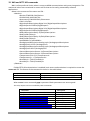
12. XML and HTTP API commands
XML is often preferred choice when it comes to M2M communication and system integration. The
monitored values are transmitted in status.xml file that can be easily processed by software
applications.
Below is the structure of the status.xml file :
<Monitor>
<Device>TCW122B-CM</Device>
<ID>00:04:A3:AA:0F:B6</ID>
<Hostname>TCW122B-CM2</Hostname>
<FW>2.12</FW>
<DigitalInput1Description>Digital In1</DigitalInput1Description>
<DigitalInput1>CLOSED</DigitalInput1>
<DigitalInput2Description>Digital In2</DigitalInput2Description>
<DigitalInput2>CLOSED</DigitalInput2>
<Relay1Description>Relay 1</Relay1Description>
<Relay1>ON</Relay1>
<Relay2Description>Relay 2</Relay2Description>
<Relay2>ON</Relay2>
<pusleWidth>1</pusleWidth>
<AnalogInput1Description>Analog Inp1</AnalogInput1Description>
<AnalogInput1>12.5V</AnalogInput1>
<AnalogInput2Description>Analog Inp2</AnalogInput2Description>
<AnalogInput2>0.3V</AnalogInput2>
<Sensor1Description>Sensor 1</Sensor1Description>
<Sensor2Description>Sensor 2</Sensor2Description>
<Temperature1>31.2°C</Temperature1>
<Temperature2>---</Temperature2>
<Humidity1>---%RH</Humidity1>
<Humidity2>---%RH</Humidity2>
</Monitor>
If XML/HTTP API authentication is enabled, basic access authentication is required to access the
status.xml file. The format of the command is shown in the table below:
XML/HTTP API authentication
enabled
disabled
Format
http://device.ip.address/status.xml?a= uuuu:pppp
http://device.ip.address/status.xml
Where uuuu is user name and pppp is password. Both parameters are unencrypted.
The relay outputs can be controlled by HTTP commands:
Command
http://device.ip.address/status.xml?r1=1
http:// device.ip.address/status.xml?r1=0
http://device.ip.address/status.xml?r2=1
http://device.ip.address/status.xml?r2=0
http://device.ip.address/status.xml?tg1=1
http://device.ip.address/status.xml?pl1=1
http://device.ip.address/status.xml?r1=1&r2=1
http://device.ip.address/status.xml?r1=0&r2=0
TCW122B-CM_R3 - June 2014
Description
Turn Relay 1 ON
Turn Relay 1 OFF
Turn Relay 2 ON
Turn Relay 2 OFF
Toggle Relay 1 state
Pulse Relay 1
Turn both relays ON
Turn both relays OFF
Page 15
If XML/HTTP API authentication is enabled, basic access authentication is required to send HTTP
commands. The format of the commands is shown in the table below (user name=admin, pass=admin):
XML/HTTP API authentication
enabled
disabled
Format
http://device.ip.address/ status.xml?a= admin:admin&r1=1
http://device.ip.address/status.xml?r1=1
13. Firmware update
TCW122B-CM supports remote firmware update. To update the device follow the steps below:
- Go to www.teracom.cc and download the latest firmware version file (v2.XX.cod) from
TCW122B-CM product page;
- Go to the device login page, enter user name and password and press the “Login” button;
- Go to “Update” menu, select the update .cod file and press “upload” button;
-
-
After the firmware update is completed, you will be forwarded to the device Login page.
Attention! Don’t turn off the power supply during the update. Turning off the power supply
will damage the device.
For some updates factory default settings procedure is mandatory.
14. Factory default settings
TCW122B-CM can be restored to its original factory default settings, following the steps below:
Turn off the power supply;
Press and hold the RESET button then turn on the power supply;
After turning the power supply release the RESET button. The LED’s STS and LOG will flash 14
times, after that only the STS LED will continue to blink. The controller is restored to its default
settings.
TCW122B-CM_R3 - June 2014
Page 16
The factory default settings are:
User Name (Admin)
Password (Admin)
IP Address
Subnet Mask
Default Gateway
SNMPConfiguration
readCommunity
writeCommunity
admin
admin
192.168.1.2
255.255.255.0
192.168.1.1
disabled
public
private
15. Over voltage protection
If the power supply voltage goes higher than 16VDC, the over voltage protection is activated.
In this mode there is a warning message on the monitoring page, the relays are inactive (OFF) and
status of LED’s is:
Sts (red) – turns ON;
Log (yellow) – flashes fast.
16. Environment information
This equipment is intended for use in a Pollution Degree 2 environment, at altitudes up to 2000
meters.
When the controller is a part of a system, the other elements of the system shall comply with the
EMC requirements and shall be intended for use in the same ambient conditions.
17. Safety
This device must not be used for medical, life saving purposes or for any purpose where its
failure could cause serious injury or the loss of life.
To reduce the risk of fire, only flexible stranded wire, with cross section 0.5mm² or larger for
wiring of digital and analog inputs and relay output of the device should be used.
To avoid electric shock and fire hazard, do not expose this product to liquids, rain, or moisture.
Objects filled with liquids, such as vases, should not be placed on this device.
There is a risk of overheating (damage) of controller, if recommended free spaces to adjacent
devices are not ensured. Joint part with external component shall have space for attachment/removal of
the cable after installation.
Teracom does not guarantee successful operation of the product if the product was used under
conditions deviating from the product specifications.
To ensure that the device works correctly follow the steps below:
ensure that the device is installed correctly, refer this user manual;
log in to the devices via browser program;
make proper set up;
set up the digital inputs to work in “dry contact” mode;
short the “Din1” and “GND”;
install sensor TSH1XX or TST1XX on 1-Wire bus;
go to “Monitoring page” of WEB interface – proper parameters value should be displayed
in the same time flashing “STS” led should indicate the proper operation.
If the equipment is used in a manner not specified by the manufacturer, the protection provided
by the equipment may be impaired.
TCW122B-CM_R3 - June 2014
Page 17
In no event will Teracom Ltd. be responsible or liable for indirect or consequential damages
resulting from the use or application of this equipment.
18. Maintenance
Upon completion of any service or repairs to the device or once per year, safety check must be
perform to determine that this product is in proper operating condition.
Clean the device only with dry cloth. Do not use a liquid cleaner or an aerosol cleaner. Do not use
a magnetic/static cleaning device (dust remover) or any kind of abrasive materials to clean the device.
TCW122B-CM_R3 - June 2014
Page 18
Appendix A
Fig.1
Fig.2
Rev.2 – February 2013
TCW122B-CM_R3 - June 2014
Page 19