1
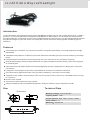
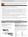
Security&Signal Equipment Engineer
Senken Group Co.,Ltd
160,West Yue Le Street,WenZhou
Phone:+86-577-88090011
Fox:+86-577-88098159
Sales E-mail:[email protected]
http://www.senken.com.cn
User Manual and Installation Instruction
LL120 Hide A Way Led Headlight
Introduction
LL120 LED Hide A-way light adopts high power Gen LEDs as light sources with unique appearance, compact
structure, convenient operation and diversified flash patterns. With superior circuit design,its characteristics
are high brightness, low working current, easy installationand long service time. it is specially designed to assist
all typed of emergency vehicles. Users can easily find out and confirm the flashing mode needed by special
indication.
Features
Ultra small, self-contained, for internal mount within composite head lamps, cornering lamps and tail light
assemblies.
selectable flash patterns, includes synchronize feature for alternating and synchronous flashing of multiple
lamps.
Flange kit options for surface mounting anywhere on your vehicle,not only a hideway mounting.
New lens technology enhances light distribution for optimum dispersion and intensity of the warning signal
at critical angles.
Aluminum base and advanced thermal heat management system is designed for endless years of trouble
free service.
Lamp and in-line lamp driver are fully encapsulated for moisture and vibration resistance.
Omni-directional lighthead mounts in any position (orientation), vertically or horizontally.
Available in red, amber, white and blue. LED color must match color of the lens it is installed behind, except
for clear lens
No RFI noise emitted.
Two screws hold the lamp securely in place.
Simple installation with no separate lamp drivers, flashers, ballast or power supplies to install.
Technical Data
Size
Units=mm
18 +_ 1
_ 0.3
31.5 +
Working voltage DC10V-DC30V
Lighting power: 10W
Colour options: Red Blue
Flash pattern: 14
Mounting Permanent
Amber
White
Installation & Operations:
This light utilizes High-intensity LED Lamps.DO NOT stare directly into the light while
it is on.As momentary blindness and/or permaent eye damage may result.
WARNING!
IMPORTANT
Please read all of the following instructions before Installing your new light.
Proper installation of this product requires the installer to have a good understanding of automotive electronics, systems
and procedures.
If mounting this product requires drilling holes, the installer MUST be sure that no vehicle components or other vital parts
could be damaged by the drilling process. Check both sides of the mounting surface before drilling begins. Also de-burr
any holes and remove any metal shards or remnants. Install grommets into all wire passage holes.
Do not install this product or route any wires in the deployment area of your air bag. Equipment mounted or located in the
air bag deployment area will damage or reduce the effectiveness of the air bag, or become a projectile that could cause
serious personal injury or death. Refer to your vehicle owner's manual for the air bag deployment area.
The User/Installer assumes full responsibility to determine proper mounting location, based on providing ultimate safety
to all passengers inside the vehicle.
For this product to operate at optimum efficiency, a good electrical connection to chassis ground must be made. The
recommended procedure requires the product ground wire to be connected directly to theNEGATIVE (-) battery post.
If this product uses a remote device to activate or control this product, make sure that this control is located in an area that
allows both the vehicle and the control to be operated safely in any driving condition.
Do not attempt to activate or control this device in a hazardous driving situation.
Use only soap and water to clean the outer lens. Use of other chemicals could result in premature lens cracking (crazing)
and discoloration. Lenses in this condition have significantly reduced effectiveness and should be replaced immediately.
Inspect andoperate this product regularly to confirm its proper operation and mounting condition.
FAILURE TO FOLLOW THESE PRECAUTIONS AND INSTRUCTIONS COULD RESULT IN DAMAGE TO THE
PRODUCT OR VEHICLE AND/OR SERIOUS INJURY TO YOU AND YOUR PASSENGERS!
Installation
Wiring&Operation:
Select the mounting location for the LL120LED headlight, keeping in mind the following:
LL120 HIDE-A-WAY LED is powered & controlled by the 4-wire cable coming from the light
assembly. Their functions are as follows:
RED: POSITIVE-Extend the REDwire to a +12VDC power source.
BLACK:GROUND- Extend BLACK wire to negative terminal of battery.
GREEN:SYNC- Connect GREEN wire to other SYNC capable lights tosynchronize output.
Cap this wire off if it is not used.
WHITE:PATTERN-Extend theWHTwire to a customer supplied momentary switch.
1.Choose a surface in the rear or bottom of the housing which is as flat as possible. Using a
hole saw, cut a 25mm hole in the housing and de-burr the hole.
2. Insert the LED lamp assembly into the reflector housing. Mark the location for the two
mounting holes . Remove the lamp assembly and drill the holes.
3. Install the lamp assembly and gasket using the two provided metal screws and
secure the lamp to the reflector assembly.
4. Remount both Lighthead assemblies to the vehicle and route the connector cables to their
designated control switches.
5. Mounting the lamp driver using the two provided metal screws.
In order to program flash patterns, the lighthead must be on. With the appropriat
lighthead(s) activated:
TO CHANGE PATTERNS:To advance to the next available pattern apply +12VDC to the
WHT wire for less than 1 second and release. To cycle back to the previous pattern apply
+12VDC to the WHT wire for more than 1 second and release.
Mounting Schematic
TO CHANGE THE DEFAULT PATTERN:When the desired pattern is displayed, allow it
to runfor more than 5 seconds. The lighthead will now display this pattern when initially
activated.
1
2
TO RESTORE THE FACTORY DEFAULT PATTERN:This will reset all patterns back to their
default settings. With the light turned off, apply power to the WHT wire. With power applied to
theWHTwire, turn light on. Allow the unit to run for 3 seconds before removing power from the
WHTwire.
A normally open momentary switch should be used to control PATTERN operation.
4
3
1.Mounting Furface
2.Gasket
3.Lighthead
4.Lamp Driver
Flash Patterns / SYNC
BLK-GROUND
RED-POWER
GRN-SYNC
WHT-PATTERN
Connect to other SYNC
capable product or cap off wire
Normally Open
Momentary Switch
SPST
Switch
1.Quad flash and Single flash
(T=710ms)
2.Quad flash
(T=710ms)
3.Double flash
(T=710ms)
4.Single flash
(T=710ms)
5.Double flash and Single flash
(T=710ms)
6.Five consecutive flash
(T=710ms)
7.Single flash 1 and Single flash 2
(T=710ms)
8.Single flash
(T=1000ms)
9.Single flash
(T=400ms)
10.Single flash
(T=200ms)
11.Single flash
(T=800ms)
12.Single flash
(T=800ms)
13.slow Single flash and Quick single flash
(T=279ms)
14.slow Single flash and Quick single flash
(T=1180ms)