1
US008306639B2
(12) Umted States Patent
(10) Patent N0.:
Diehl et al.
(54)
US 8,306,639 B2
(45) Date of Patent:
HOME AUTOMATION GROUP SELECTION
Nov. 6, 2012
FOREIGN PATENT DOCUMENTS
BY COLOR
JP
2001-307505 A
(75) Inventors: William Diehl, Dove Canyon, CA (US);
11/2001
(Continued)
Sonny Windstrup, Copenhagen (DK);
(73)
Karl Jonsson, Rancho Santa Margarita,
CA (Us)
AssigneeZ Greenwave Reality, Pte, Ltd‘,
OTHER PUBLICATIONS
Hart, G. W, Nonintrusive appliance load monitoring, Porceedings of
the IEEE, vol. 80, No. 12, Dec. 1, 1992, pp. 1870-1891, IEEE, New
Singapore (SG)
( * ) Notice:
York’ NY’ Us‘
Subject to any disclaimer, the term of this
(Connnued)
gage? 11Ssizgilgilejog disgusted under 35
' i
i
Primary Examiner * Kidest Bahta
i
(74) Attorney, Agent, or Firm * Bruce A. Young
(21) Appl. N0.: 12/795,381
(57)
(22)
A networked device is disclosed comprising means for con
Filed:
Jun‘ 7’ 2010
(65)
Prior Publication D at a
ABSTRACT
trolling a state of the networked device, means for connecting
to a network, means for allow1ng a user to select a color from
Us 2011/0098831 A1
. . Related
(60)
51
(
)
APL 28’ 2011
a plurality of colors, the plurality of colors having at least one
_
_
locking color and one or more non-locking colors, and means
Apphcatlon Data
for generating a selected color code corresponding to the
PrOVlSlOnéll appllcatlon NO. 61/254,709, ?led O11 00125, 2009-
color selected by the user, each color of the plurality of colors
having a corresponding color code. The networked device
I
submits the selected color code over the network for use by
the network controller in con? urin the device and chan es
Cl
nt'
'
(52)
G06F 19/00
(2011 01)
'
U,' S ' Cl ' """ "I """ ", """"" " 700/90‘’ 307/38‘’ 315/307
(58)
Field of Classi?cation Search .................. .. 715/38,
715/734’ 751; 341/176’ 23’ 34; 345/173’
S
1-
fth
0
selected by the user. In some embodiments, the networked
device further comprises means for allowing the user enter a
local control command wherein the means for controlling the
networked device changes the state of the networked device
in response to the local control command only if the color
US. PATENT DOCUMENTS
8/1989 Hart et al.
4/1990 Markkula et al.
11/1993 Pawlick
5,301,122 A
4/1994 Halpern
5,483,153 A
1/1996 Leeb et al.
1 k.
1
I
b d.
t
e one ormore non- 00 mg co ors. 11 some em 0 1men s
thte
networketd dev1te1ee als?
reslpondis to riequestts {Ere statlus
1n orma 1on rom
ne wor 1n epen en 0
co or
15 Dry
References Cited
4,858,141 A
4,918,690 A
5,258,656 A
selected by the user is one of the one or more non-locking
colors. And in some embodiments that means for controlling
the networked device controls the On/ Off state.
21 Claims, 9 Drawing Sheets
(Continued)
100
f/
101
Num
g
p
?l f
e or Comp e e Seam
g
from the network only if the color selected by the user is one
3 4 5 /1 5 6; 700/90;
315/307;
307/8
1 t
h h- t
'
t-
ee app 10a 1on
(56)
g
the state of the networked device in res onse to a command
102
104
103
1 05
106
Computer Colors
Print Colors
M%
‘(D/n
R
G
50
50
5o
O
O
0
100
O
O
31
21
5O
O
O
O
100
O
227
100
O
255
O
O
132
0
250
O
75
O
255
O
255
B
O
US 8,306,639 B2
Page 2
U.S. PATENT DOCUMENTS
5,519,878
5,650,771
5,717,325
5,754,963
6,038,523
6,160,551
6,476,729
6,492,897
A
A
A
A
A
A
B1
B1
5/1996
7/1997
2/1998
5/1998
3/2000
12/2000
11/2002
12/2002
6,501,463 B1 *
6,987,444 B2
Dolin, Jr.
Lee
Leeb et al.
Nunneley et a1.
Akahane et al.
Naughton et al.
Liu
Mowery
12/2002 Dahley et al. ............... .. 345/173
1/2006 Bub et al.
6,993,417 B2
1/2006 Osann, Jr.
7,355,523 B2 *
4/2008
2006-525640
2008-123727
10-2002-0034855
03-026358
2003026358
2003077100
2005039144
2009084016
al'
Bejean et a1‘
A
A
A
A1
A1
A1
A1
A2
11/2006
5/2008
5/2002
3/2003
3/2003
9/2003
4/2005
7/2009
WO
2009097400 A1
8/2009
WO
2011050224 A1
4/2011
Sid ............................. .. 340/916
gains:
>$<
FOREIGN PATENT DOCUMENTS
JP
JP
KR
WO
WO
WO
WO
WO
OTHER PUBLICATIONS
Jiang et al., Design and Implementation of a High-FidelityAC Meter
‘‘‘‘‘‘‘‘‘‘‘‘‘‘‘‘‘“
Network
709, San Francisco,
13-16,
, San Fran
7,g76,255 B2 *
1/2011 Conway et a1, ,,,,,,,,,,,,, ,, 341/176
cisco, CA, USA ACM 978-1-60558-371-6/09/04.
7,835,917 B2
7,956,546 B2
2/2011 Kuhns et a1,
6/2011 Hasnain
7,961,111 B2
7,970,542 B2
8,013,545 B2
6/2011 Tinaphong et al.
6/2011 Bent et al.
9/2011 Jonsson
Non-Final Of?ce Action for U.S. Appl. No. 13/195,655, USPTO,
Jun. 21, 2011.
K. Jonsson, “Modular Networked Light Bulb,” GWRPID-002A,
Unpublished U.S. Appl. No. 12/795,395, ?led Jun. 7, 2010.
“Lamp Module Receiver PLM03 User Manual,” X10, Inc. 2008,
8,049,655 B2 *
2002/0152045 A1 *
2003/0025840 A1 *
2003/0050737 A1
11/2011 Conway et al. ............. .. 341/176
10/2002 Dowling et al.
. 702/107
2/2003 Arling ......................... .. 348/734
3/2003 ()Sann
http://www.X10pro.com/pro/pdf/plm03.pdf retrieved on May 25,
2010.
W. Diehl, “Networked Light Bulb with Color Wheel for Con?gura
tion,” GWRPID-OOZB, Unpublished U.S. Appl. No. 12/795,406,
2003/0197772 A1*
10/2003
Iwatsuki et al. ............ .. 347/104
?led Jun 7 , 2010
2006/0202557
2006/0271544
2007/0135973
2007/02971 12
Zoos/0094210
9/2006
11/2006
6/2007
12/2007
4/2008
Menas et 31,
Devarakonda et a1‘
Petite
Gilben
Paradiso et a1‘
K. Jonsson, “Networked Device with Power Usage Estimation,”
GWRPID-002C, Unpublished U.S. Appl. No. 12/795,417, ?led Jun.
7, 2019
K. Jonsson, “Power Node for Energy Management,” GWRPID-006,
Unpublished U.S. Appl. No. 12/777,229, ?led May 10, 2010.
A1
A1
A1
A1
A1
Zoos/0201268 A1>x<
8/2008 Duncan “““““““““““““ “ 705/80
Zoos/0270937 A1>l< lo/zoog poulet et a1‘ ““““““““ “ 715/810
K. Jonsson, “Automated Load Assessment Device and Method,”
GWRPID-001A, Unpublished U.S. Appl. No. 12/795,629, ?led Jun.
2009/0059603 A1
3/2009 Recker et al.
7, 2010
2009/0202250 A1 *
g/2009 Dizechi et a1, ,,,,,,,,,,,,,, ,, 398/107
A. Pudenzi, A Neuron Nets Based Procedure for Identifying Domes
2009/0234512 A1
2009/0236909 A1
2009/0237006 A1
9/2009 Ewing et a1,
9/2009 Aldag et al.
9/2009 Champion et al.
tic Appliances Pattern of Use from Energy Recordings at Meter
Panel, IEEE, 2002
Non-Final Of?ce Action for U.S. Appl. No. 12/795,629, USPTO,
2009/0267540 A1
2009/0322159 A1
10/2009 Chemel et al.
12/2009 DuBose et al.
Oct. 24, 2011.
Notice ofAllowance for U.S. Appl. No. 12/795,395, USPTO, Jul. 22,
2010/0005331 A1
1/2010 Somasundaram et al.
2011.
2010/0084992
2010/0090542
2010/0141153
2010/0145542
2010/0191487
2011/0031819
2011/0062874
201 l/0098867
4/2010
4/2010
6/2010
6/2010
7/2010
2/2011
3/2011
4/20ll
Notice of Allowance for U.S. Appl. No. 12/777,229, USPTO, Nov.
26, 2011.
Notice of Allowance for U.S. Appl. No. 12/795,629, USPTO, Mar.
29, 2012,
Notice ofAllowance for U.S. Appl. No. 12/795,629, USPTO,Apr. 18,
2012,
International Search Report and Written Opinion for PCT/US2010/
53641, European patent Office, Mar‘ 4, 2011‘
A1
A1
A1
A1
A1
A1
A1
Al
2011/0309735 A1
2012/0126699 A1
Valois et al.
Johnson et al.
Recker et 81.
Chapel et al.
Rada er :11
Gunwall
Knapp
Jonsson et al.
12/2011 Parker et a1.
5/2012 Zittel et al.
* cited by examiner
US. Patent
Nov. 6, 2012
Sheet 1 of9
US 8,306,639 B2
100
101
102
103
104
Print Colors
FIG. 1
C 0m
410. DU5m
106
C 0 wrS
Fill
US. Patent
Nov. 6, 2012
Sheet 2 of9
US 8,306,639 B2
// 220
221
f/ 200
213
203
214
210
202
202
204
W205
206 A
1
1
=2
i
\\/v
208
207
US. Patent
Nov. 6, 2012
Sheet 3 of9
300
304
301
FIG. 3
US 8,306,639 B2
US. Patent
Nov. 6, 2012
Sheet 4 of9
US 8,306,639 B2
407
403
+V
R1
l
401
\
§7 //
400
+V
R2?
l
V\?reless
NetWOrk
Adapter
Controller ‘
Power
Supply
406
304
305
H
I
FIG. 4
US. Patent
515
NOV. 6, 2012
Sheet 5 (69
US 8,306,639 B2
501
Incoming state
_
I
502
/
Turn control
electronics “On”
504
|nitia|ized/
Wait for user to
In I d d’)
Press physical sync
Cu 9
button.
-
516
505
Send Selected
Broadcast Inclusion
group (color)
packet
508
506
Yes
Enable Monitoring
Receive
Initialization
Info?
509
ls Color
Selector
White?
Yes
510
511
Receive Device
State Control
Turn device on
and ignore all
state changes
512
Turn
Device On?
FIG. 5
513
514
Turn Device Off
Turn Device On
No
US. Patent
Nov. 6, 2012
Sheet 6 of9
US 8,306,639 B2
603
610
611
612 613
614 615
616 617
618 619
// 600
602
603
640
\\
642
630
603
609
614
602
606
607
609
FIG. 6
641
643
US. Patent
NOV. 6, 2012
Sheet 7 669
US 8,306,639 B2
// 700
740
FIG. 7
US. Patent
Nov. 6, 2012
Sheet 8 of9
US 8,306,639 B2
802
801
803
814
812
811
FIG. 8B
804
FIG. 8A
823
I
822
/
\
821
831
FIG. 8C
/833
832
\
FIG. 8D
8
US. Patent
Nov. 6, 2012
Sheet 9 of9
900
US 8,306,639 B2
901
902
911
910
I On/Off
ISync
Color
903
904 905 906
FIG. 9
US 8,306,639 B2
1
2
HOME AUTOMATION GROUP SELECTION
BY COLOR
electrical contacts With encoded bit pattern stored in an optics
holder. The passive storage may include passive RFID.
X10 markets a series of home automation control modules
such as the PLM03 Lamp Module Receiver. Many X10 mod
CROSS-REFERENCE TO RELATED
APPLICATIONS
ules include tWo rotary control dials that the user can set at
installation to alloW each separate module to be indepen
dently controlled. One dial is for the “House Code” and canbe
This application claims the bene?t of US. Provisional
Patent Application Ser. No. 61/254,709 entitled “HYBRID
LIGHT” and ?led on Oct. 25, 2009, then entire contents of
set to a letter ranging from “A” to “P” While the other dial is
for the “Unit Number” Which can be set to a number ranging
from 1 to 16.
Which is hereby incorporated by reference.
It should be noted that neither the system described by
BACKGROUND
Chemel et al. nor X10 devices address simplifying the Way
that the user can identify the location or other parameters of a
1. Technical Field
The present subject matter relates to home automation
networking. It further relates to initialiZation and setup of
netWorked home automation devices.
device.
It therefore is important to provide a neW method for the
user to very easily con?gure a netWorked device for the home.
The method should be very easy to remember and provide a
simple means to con?gure at least the location or other basic
2. Description of Related Art
Providing home automation functionality using netWork
ing means is Well knoWn in the art. Control of lighting and
parameter important to the netWorking of the device.
20
appliances can be accomplished using systems from many
SUMMARY
different companies such as X10, lnsteon® and Echelon.
These systems all require some kind of initialiZation and
setup of the devices to communicate properly on the netWork.
Various embodiments of the present subject matter dis
close methods and apparatus for con?guring a netWorked
device. One disclosed method comprises generating a
In some cases some of the initialiZation and setup is pre 25
de?ned in the device With no mechanism for the user to easily
selected color code corresponding to a color selected from a
plurality of colors, each color of the plurality of colors having
con?gure the device for their particular installation. But in
many cases, a Way for the user to con?gure the device at the
a corresponding color code and sending the selected color
time of installation is required.
US Pat. App. No. 2009/0237006 ?led Mar. 18, 2008 by
code over a netWork. In some embodiments, the plurality of
30 colors have at least one locking color and one or more non
locking colors and the netWorked device changes a state of the
inventors Champion et al. shoWs a method and apparatus for
identifying a group of devices Where a controller receives a
networked device in response to a command received over the
netWork only if the color selected is one of the one or more
color identifying value over a communication channel from a
management netWork and then combines the light emitted by
the at least tWo LEDs into an identifying color that identi?es
a group of devices. In US. Pat. No. 4,918,690 issues on Apr.
17, 1990, the inventors Markkula et al. describe a netWork for
non-locking colors. In at least one embodiment, the command
35
of the netWork device being changed is an On/Off state. In
some embodiments the state of the netWorked device is set to
sensing, communicating and controlling Where each cell in
the netWork is assigned a group identi?cation number.
Inventor Dolin describes an apparatus and method for net
Work node identi?cation and netWork con?guration in US.
Pat. No. 5,519,878 issued on May 21, 1996. In Dolin’s sys
tem, each device in the home automation netWork contains a
unique ID that is obtained at the time of installation and then
received over the netWork is an On/ Off command and the state
On if the color selected is the at least one locking color. And
in some embodiments the netWorked device responds to a
40
request for status information from the netWork independent
of the color selected. In another embodiment the netWorked
light bulb receives a local control action and changes the state
of the netWorked lighting apparatus in response to the local
control action only if the color selected is one of the one or
placed on a machine readable medium such as a bar code 45 more non-locking colors. In some embodiments the local
sticker. The bar code stickers for each device are then placed
on paper ?oor plan to shoW the physical location of that
device. The paper ?oor plan With the stickers is then read by
an automatic con?guration device to determine the physical
location of each device for future use.
control command is an On/ Off command and the state of the
netWork device being changed by the local control command
is an On/Off state.
50
One embodiment is a netWorked device comprising means
for controlling a state of the netWorked device, means for
HoWever, neither Champion et al., Markkula et al. nor
connecting to a netWork, means for alloWing a user to select a
Dolin address the ability of a user to set the netWork group or
color from a plurality of colors, the plurality of colors having
other parameters using a control mechanism on the device
itself.
In US Pat. App. No. 2009/0267540, inventors Chemel at al.
at least one locking color and one or more non-locking colors,
55
shoW an intelligent LED lighting system With mesh netWork
ing connectivity. Chemel et al. describe a poWer management
module (PMM) With light module identi?cation. Each light
module may have identifying information programmed into
it, and can communicate that information to the PMM, Which
60 color selected by the user is one of the one or more non
locking colors. In some embodiments the netWorked device
also responds to requests for status information from the
netWork independent of the color selected by the user. In
some embodiments, the netWorked device further comprises
can in turn store and communicate that information to a user
or installer to aid in replacement or commissioning. The
information may be stored in a nonvolatile memory onboard
the light module, and communicated via a digital bus to the
PMM. The information may be stored passively on the light
module, such as via a series of jumpers or dip sWitches, and
can be read by the PMM. The passive storage may include
and means for generating a selected color code corresponding
to the color selected by the user, each color of the plurality of
colors having a corresponding color code. In that embodi
ment the netWorked device submits the selected color code
over the netWork but changes the state of the netWorked
device in response to a command from the netWork only if the
65
means for alloWing the user enter a local control command
Wherein the means for controlling the netWorked device
changes the state of the netWorked device in response to the
US 8,306,639 B2
3
4
local control command only if the color selected by the user is
axis. In some embodiments the color wheel may also include
one of the one or more non-locking colors. And in some
visible tactilely recogniZable symbols.
embodiments that means for controlling the networked
device controls the On/Off state.
In another embodiment, a networked device is comprised
BRIEF DESCRIPTION OF THE DRAWINGS
The accompanying drawings, which are incorporated in
and constitute part of the speci?cation, illustrate various
embodiments of the invention. Together with the general
description, the drawings serve to explain the principles of the
invention. In the drawings:
of a controller, a network adapter communicatively coupled
to the controller, and a color selection mechanism communi
catively coupled to the controller. The color selection mecha
nism allows a user to select a color from a plurality of colors,
the plurality of colors having at least one locking color and
FIG. 1 shows a table of color de?nitions used in this dis
one or more non-locking colors. The color selection mecha
closure;
nism communicates information corresponding to the color
FIG. 2 shows an embodiment of a of color selection mecha
selected by the user to the controller and the controller con
nism;
verts the information communicated by the color selection
FIG. 3 shows a networked single outlet AC power socket;
FIG. 4 shows a block diagram of the electronics for one
mechanism to a color code corresponding to the color
selected by the user. The controller communicates the color
embodiment;
code to the network adapter and the network adapter sends the
color code out over the network. If the network adapter
receives a message from the network to change a state of the
networked device it is communicated to the controller, but the
controller changes the state of the networked device in
response to the message to change the state of the networked
FIG. 5 is a ?owchart describing how the color selection
means is used in the con?guration of a networked home
20
FIG. 6 shows an alternative embodiment of a of color
selection mechanism;
FIG. 7 shows a different alternative embodiment of a of
device communicated by the network adapter only if the color
selected by the user is one of the one or more non-locking 25
colors.
In some embodiments, the network adapter connects to a
wireless network such as Wi-Fi, Z-wave or Zigbee and in
some embodiments the controller and the network adapter are
integrated on a single integrated circuit. In other embodi
ments, the network adapter receives a status request message
over the network and communicates it to the controller; and
the controller responds to the status request message by com
municating a response message to the network adapter to send
out over the network, the controller responding independent
of the color selected by the user. Yet another embodiment
includes a local control interface communicatively coupled to
the controller, the local control interface allows the user to
enter a local control command to request a change to the state
of the networked device and the controller changes the state of
the networked device in response to the local control com
mand only if the color selected by the user is one of the one or
more non-locking colors.
In some embodiments the color selection mechanism may
be a graphical user interface. In some embodiments the color
selection mechanism may have a rotary switch with a rotat
color selection mechanism;
FIGS. 8A, 8B, 8C and 8D show additional embodiments of
color selection mechanism; and
FIG. 9 shows an embodiment using a touch sensitive
graphical user interface.
30
DETAILED DESCRIPTION
In the following detailed description, numerous speci?c
details are set forth by way of examples in order to provide a
thorough understanding of the relevant teachings. However, it
35
should be apparent to those skilled in the art that the present
teachings may be practiced without such details. In other
instances, well known methods, procedures and components
40
have been described at a relatively high-level, without detail,
in order to avoid unnecessarily obscuring aspects of the
present concepts. A number of descriptive terms and phrases
are used in describing the various embodiments of this dis
closure. These descriptive terms and phrases are used to con
45
vey a generally agreed upon meaning to those skilled in the art
unless a different de?nition is given in this speci?cation.
Some descriptive terms and phrases are presented in the fol
lowing paragraphs for clarity.
able shaft and an output communicatively coupled to the
The term “network” refers to a bidirectional communica
tion medium and protocol to allow a plurality of devices to
communicate with each other.
controller and a color wheel having a center, an edge and a
colored area, the center of the color wheel coupled to the shaft
of the rotary switch and the colored area divided into sections,
each section imprinted with a section color selected from the
plurality of colors. As the color wheel is rotated by user
manipulation of the edge, the colored area of the color wheel
and the rotatable shaft of the rotary switch also rotate and the
output of the rotary switch communicates current rotational
automation device;
50
The term “networked device” refers to any device that can
communicate over a network.
Reference now is made in detail to the examples illustrated
in the accompanying drawings and discussed below.
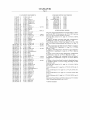
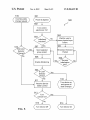
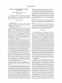
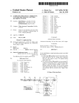
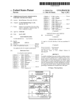
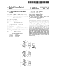
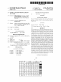
FIG. 1 is a table 100 indicating some embodiments of the
55
position information corresponding to the color selected by
colors that could be used with the subject of the present
disclosure. The ?rst column 101 contains reference numbers
the user to the controller. The position of the color wheel may
0-9 to be used to referring to each color. Some embodiments
be indicated by a selection mark in close physical proximity
may use fewer than 10 colors while others may use more than
10 colors. The second column 102 contains symbols that may
to the section of the colored area of the color wheel imprinted
the user at the current position. In other embodiments, the
optionally be imprinted on top of the color to help people who
may have dif?culty distinguishing between different colors.
position of the color wheel may be indicated by the color of
In this embodiment, the ?rst color has no symbol, the next 8
section of the colored area that is visible through an aperture
in an outer housing of the networked device and the color
wheel is mounted so that a portion of the edge protrudes from
the outer housing of the networked device allowing the user is
able to manipulate the edge to rotate the color wheel about the
colors use an Arabic numeral as the symbol, and the ?nal
with the section color corresponding to the color selected by
60
symbol is a padlock. Other symbols may be used in other
65
embodiments. The third column 103 contains the color names
for the colors of this embodiment. Other colors could be used
in other embodiments. The next four columns 104, entitled
US 8,306,639 B2
5
6
“Print Colors”, give one possible set of colors to be mixed for
4-color printing processes. The four columns 104 represent
the percentage of the maximum amount of ink for the cyan (C
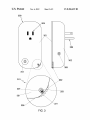
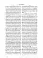
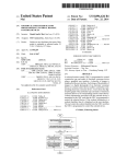
netWorked device 300 is a controllable single outletAC poWer
socket but other embodiments may implement the disclosed
%), magenta (M %), yellow (Y %), and black (K %) and can
to, a multi-outlet poWer strip, a kitchen appliance such as a
coffee maker, a garage door opener, an audio-video compo
subject matter in other appliances including, but not limited
range from 0% to 100%. Other mixes might be used for some
embodiments depending on the speci?c inks, print stock and
nent, a computer peripheral, a lighting ?xture, an electric
heater, a fan, or any type of electrical device, either AC or
exact desired color. The next three columns 105, entitled
“Computer Colors”, give a possible representation for the
battery poWered. The netWorked device 300 of this embodi
indicated colors for use on a computer screen. The three
ment has a front beZel 301, a rear case 302, a poWer sWitch
columns 105 represent a color value for each of red (R), green
(G) and blue (B) and range from 0 to 255 to alloW the value for
each component color to be stored in a single 8 bit storage
location as is common in computer systems. The ?nal (right
303, a sync button 309, a socket 304 and a plug 305. Circuitry
is inside the netWorked device 300 including a controller, a
netWork adapter, and a thyristor (not shoWn) that is able to
control Whether or not AC poWer from the plug 3 05 is alloWed
to pass to the socket 304. The color selection mechanism 220
is located at the bottom right of the netWorked device 300 and
most) column 106, entitled “Fill”, gives a cross-hatch pattern
to be used in the following black and White ?gures to indicate
is shoWn in greater detail in the enhanced vieW 310. The edge
202 of the color Wheel 221 protrudes beyond the outer rim
the color that Would ?ll a particular area.
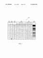
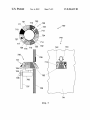
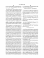
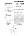
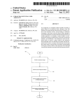
FIG. 2 shoWs one particular embodiment of a color selec
tion mechanism 220 to alloW a user to select a color. Top vieW
200 shoWs the color Wheel 221 from the top and side vieW 201
shoWs the color Wheel 221 from the side With some associated
structure that has been omitted from the top vieW 200 for
clarity. The color selection mechanism 220 has color Wheel
221 With an edge 202 and a hub 204. The edge 202 may be
knurled or textured to give better grip as it is rotated by the
user. A colored area 203 is included on the color Wheel 221. In
this embodiment, the colored area 203 is implemented as a
306 of the beZel 301 and case 302 of the netWorked device
300. This alloWs the user to apply a rotational force to the
20
color Wheel 221. As the color Wheel 221 rotates, different
25
visible through an aperture 307 in the beZel 301. In FIG. 3, the
current position of the color Wheel 221 is such that White
(locked) section of the colored area 203 is visible. The color
selection mechanism 220 may be designed to provide a detent
sections of the colored area 203 of the color Wheel 221 are
at each section of the colored area 203 to make it clear What
color is currently selected.
label attached to the top of the color Wheel 221 With adhesive
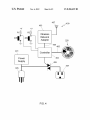
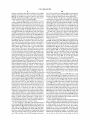
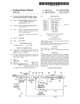
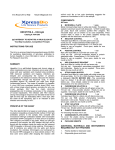
FIG. 4 shoWs a block diagram of the control electronics 400
so that the center of the colored area 203 is coincident With the
center of the color Wheel 221. The colored area 203 is divided
into sections 210-219, each section imprinted With a different
color as de?ned in FIG. 1. In this embodiment, section 210 is
imprinted With color 0 and no identifying symbol. In this
embodiment, color 0 is black. Section 211 is imprinted With
color 1 and the symbol “1”. Section 212 is imprinted With
color 2 and the symbol “2”. Section 213 is imprinted With
color 3 and the symbol “3”. Section 214 is imprinted With
color 4 and the symbol “4”. Section 215 is imprinted With
color 5 and the symbol “5”. Section 216 is imprinted With
color 6 and the symbol “6”. Section 217 is imprinted With
color 7 and the symbol “7”. Section 218 is imprinted With
color 8 and the symbol “8”. Section 219 is imprinted With
30
used in the netWorked device 300. The plug 305 provides AC
poWer to the poWer supply 401 Which generates the necessary
poWer for the rest of the electronics. A Wireless netWork
adapter 403 receives radio frequency signals through antenna
35
407 and is connected to controller 402 by a digital bus 404. In
some embodiments, the Wireless netWork adapter may con
nect to a Z-Wave, Zigbee (802.15) or Wi-Fi (802.11)Wireless
netWork. Other embodiments may use a Wired or poWer line
netWork adapter instead of a Wireless netWork adapter. In
some embodiments, the controller 402 is implemented as a
microcontroller and in some embodiments, the controller,
40
Wireless netWork adapter, and digital bus may be integrated
onto a single chip such as the Zensys ZM3102. A user inter
color 9 and the symbol of a padlock. In this embodiment color
face is provided through several locally manipulatable con
9 is White. The colors imprinted on the colored area 203
trols. In this embodiment, a poWer button 408 is connected to
a voltage source through a resistor 402 and a sync button 409
is connected to a voltage source through a resistor R2. Both
buttons 408 and 409 are connected to the controller 402. A
color selection device 220 is also connected to the controller
represent nine non-locking colors 0-8 and one locking color 9
Which is White. Other embodiments may use more or less than 45
ten colors. The color Wheel hub 204 is attached to the shaft
205 of a rotary dip sWitch 206 that may be mounted on a
printed circuit board 207. As the color Wheel 221 is turned, it
turns the shaft 205 of the rotary dip sWitch 206 Which gener
ates a color code depending on the rotational angle of the shaft
205. The color code is then available on the pins 208 (not all
402 providing rotational position information through con
50
selected by the user. In other embodiments the user interface
may be provided using other means such as a graphical user
pins are shoWn) of the rotary dip sWitch 206. The pins 208
may be connected to pull-up resistors and a controller located
on the same printed circuit board (or elseWhere in the net
Worked device). In one embodiment the rotary dip sWitch is a
BCD encoder that generates 4 bits of output that can either be
interface on a display or a keypad or any other device or
55
connected to ground or left as an open circuit so that as each
output is connected to a pull-up resistor, the output represents
a binary number betWeen 0000 and 1010. Other methods of
encoding the angular position of the color Wheel 221 could
nection 405. The controller 402 converts the rotational posi
tion information to the color code corresponding to the color
60
combination of devices that alloWs the user to provide input to
the controller 402. The controller 402 can control a thyrister
406 to determine Whether or not the socket 304 is poWered.
Other embodiments may use a relay or other controllable
poWer sWitch.
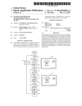
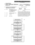
FIG. 5 shoWs a How chart 500 for the operation of the
netWorked device 300 of the current subject matter. The exact
also be used such as individual sWitch outputs for each rotary
order of operations and details shoWn in this How chart 500
position, an analog to digital converter measuring a voltage
may differ betWeen embodiments but one skilled in the art can
across a potentiometer, an optical shaft encoder, a magnetic
detector, tWo-axis hall-effect sensors or other Well-knoWn
methods of detecting the angular position of a disk or shaft.
FIG. 3 shoWs the color selection mechanism 220 imple
mented in a netWorked device 300. In this embodiment the
see hoW the concepts presented herein Would still apply. After
poWer is applied 501, the netWorked device 300 turns 400 the
65
control electronics on. The controller 402 then checks 503 to
see if the device has been previously initialized and included
into the netWork. If the device has not yet been initialized and
US 8,306,639 B2
7
8
included into the network, it Waits 504 until the user presses
the sync button 409. Once the sync button 409 has been
pressed, the controller 402 broadcasts 505 an inclusionpacket
color has changed 516, the controller 402 sends the neW color
out over the netWork to let the netWork controller knoW that
the user has changed the color code on the device. The con
troller then proceeds through the same set of steps 508-514 as
described in the initial poWer-up sequence. If the color has not
changed 516, there is no need to rebroadcast the color code or
recheck to see if the color is White, so the controller simply
over the netWork to let a netWork controller knoW that there is
a neW device on the netWork that needs to be initialiZed and
con?gured. The controller 402 then Waits 506 for some period
of time to receive initialiZation information from the netWork
controller. If no initialiZation information is received, the
controller rebroadcasts 505 an inclusion packet and Waits
receives 511 the control packet and takes appropriate action
512-514.
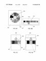
FIG. 6 shoWs an alternative embodiment of a color selec
tion mechanism 600 to alloW a user to select a color. Top vieW
620 shoWs the color Wheel from the top and side vieW 630
shoWs the color Wheel from the side With some associated
structure that has been omitted from the top vieW 620 for
clarity. The color Wheel mechanism 600 has a color Wheel
again, repeating this process until initialiZation information is
received 506. Once initialization information has been
received, the controller 402 generates the color code from
information received from the color selection mechanism 220
and sends 507 the color code out to the netWork controller.
The netWork controller uses the color code to help further
con?gure the device and create a more user-friendly user
interface for the entire network. One Way the netWork con
troller may use the color code is to alloW the user to assign a
particular color to a room and set all the netWorked devices
located in that room to the same color. An alternative use is to
differentiate all similar devices using a different color so that
the user can easily tell Which device is Which as they interact
With the netWork controller. In yet another use, the color can
be used to group devices together that interact such as all the
audio-visual devices. In some embodiments, a speci?c color,
such as black, may be interpreted by the netWork controller as
meaning that the device is not assigned to a particular group
With a raised disc 601, an edge 602 extending out beyond the
raised disc, and a hub 604. The edge 602 may be knurled or
textured to give better grip as it is rotated by the user. A
20
that is Wrapped around the raised disc 601 and attached With
adhesive. The colored area 603 is divided into sections 610
619, each section imprinted With a different color as de?ned
25
and the controller can ask the user Which group the device
should be assigned to. In other embodiments that require
more than 8 distinct color assignments, the netWork controller
may alloW the user to select from a plurality of additional
30
colors, beyond the colors directly available from the color
selection mechanism of the device, so that the user can have
a larger choice of colors available for device assignment.
After the color code has been transmitted 507, the control
ler 402 may enable monitoring 508 of the status of the device.
35
A netWorked device may alloW the netWork controller or
other netWork devices to query its current state, current poWer
usage, current condition of its consumables used by the net
Worked device, diagnostic information or other information
colored area 603 is included on the color Wheel. In this
embodiment, the colored area 603 is implemented as a label
40
in FIG. 1. In this embodiment, section 610 is imprinted With
color 0, section 611 is imprinted With color 1, section 612 is
imprinted With color 2, section 613 is imprinted With color 3,
section 614 is imprinted With color 4, section 615 is imprinted
With color 5, section 616 is imprinted With color 6, section
617 is imprinted With color 7, section 618 is imprinted With
color 8, and section 619 is imprinted With color 9. In this
embodiment, no symbols are included With the colors
although other similar embodiments may include visible or
tactilely recogniZable symbols on one or more of the sections
610-619. The colors imprinted on the colored area 603 rep
resent nine non-locking colors 0-8 and one locking color 9
Which is White. The color Wheel hub 604 is attached to the
shaft 605 of a rotary dip sWitch 606 that may be mounted on
a printed circuit board 607. As the color Wheel is turned, it
turns the shaft 605 of the rotary dip sWitch 606 Which gener
ates a set of open or closed sWitches depending on the rota
available to the netWorked device that other devices on the
tional angle of the shaft 605. The color code is then available
netWork might ?nd useful. The controller 402 then deter
mines 509 if the color selected is the locking color, in this case
White. If the locking color has been selected, the controller
then turns (or leaves) the device in an operating “on” state but
ignores 510 all control requests that may come in over the
netWork. In some embodiments, the controller may also
ignore all local control requests such as the user pressing the
poWer button 408 if the locking color has been selected.
If the color selected 509 on the color selection mechanism
420 is not White, the controller 402 then is enabled to receive
511 control packets over the netWork. If the control packet
tells the controller 402 to turn the device On 512, the control
ler 402 controls the thyristor 406 to alloW the socket 304 to be
energiZed 514. If the control packet tells the controller 402 to
turn the device Off 512, the controller 402 controls the thy
ristor 406 to isolate the socket 304 from electrical poWer,
turning it off 513. Depending on the capability of the net
Worked device, many states other than the On/ Off state may
be controlled. On occasion neW incoming state change
requests may be received 515. Those state change requests
on the pins 608 (not all pins are shoWn) of the rotary dip
sWitch 606. The pins 608 may be connected to pull-up resis
tors and a controller located on the same printed circuit board
45
output that can either be connected to ground or left as an
open circuit so that as each output is connected to a pull-up
50
sWitch outputs for each rotary position, an analog to digital
converter measuring a voltage across a potentiometer, an
optical shaft encoder, a magnetic detector, tWo-axis hall-ef
55
fect sensors or other Well-knoWn methods of detecting the
angular position of a disk or shaft.
A cross section of a Wall 609 of the netWorked device
shoWs the edge 602 protruding through the Wall and a portion
60
local user interface on the device. Whenever a neW state
of the colored area 603 visible through an opening in the Wall
609. Exterior vieW 640 shoWs the outside of the netWorked
device With the Wall 641 having an opening 642. In this
embodiment, the opening 642 has a Wider section at the
bottom to alloW the edge 602 to protrude from the Wall 641
While keeping the upper portion of the opening 642 narroWer
change request is received 515, the controller 402 checks to
device 220 has changed 516. In some embodiments, the act of
changing the color may generate a state change request. If the
resistor, the output represents a binary number betWeen 0000
and 1010. Other methods of encoding the angular position of
the color Wheel could also be used such as such as individual
may come over the netWork or they may be received from a
see if the color selected by the user on the color selection
(or elseWhere in the netWorked device). In one embodiment
the rotary dip sWitch is a BCD encoder that generates 4 bits of
65
so that can be mostly ?lled With one section of the color
Wheel. In the position shoWn, section 614 is ?lling most of
opening 642. To help make it even clearer Which color is
US 8,306,639 B2
9
10
selected, an indicator arrow 643 is included on the Wall 641
color. The color selection mechanism 700 may be designed to
provide a detent at each section 710-717 to make it easy for
the user to center the desired section in the opening 742.
FIGS. 8A, 8B, 8C and 8D shoW additional alternative
pointing at the current color. The color selection mechanism
600 may be designed to provide a detent at each section
610-619 of the colored area 603 to make it easy for the user to
center the desired section. in the opening 642.
embodiments of a color selection mechanism. FIG. 8A shoWs
a netWorked device 801 With a non-moveable color Wheel 802
FIG. 7 shoWs another alternative embodiment of a color
selection mechanism 700 to alloW a user to select a color. Top
imprinted or a?ixed to the netWorked device 801. A rotatable
selector 803 can be turned by the user to select a color. The
section 804 of the non-moveable color Wheel 802 With the
color “5” is selected at the current position of the rotatable
vieW 720 shoWs the color Wheel from the top and side vieW
730 shoWs the color Wheel from the side With some associated
structure that has been omitted from the top vieW 720 for
clarity. The color Wheel mechanism 700 has a color Wheel
With an angled side 701, an edge 702 at the outermost part of
the angled side 701, and a hub 704. The angle of the angled
side 701 may range from 0 (parallel With the axis) to nearly 90
degrees (nearly ?at as shoWn in FIG. 2). The edge 702 may be
knurled or textured to give better grip as it is rotated by the
selector 803. Means to convert the angular position of the
rotatable selector 803 to a color code Would also be included.
FIG. 8B shoWs a linear color selector. NetWorked device
811 has a color label 812 af?xed. Sliding selector 813 can be
moved back and forth by the user to select a color. A linear
slide sWitch moved by the sliding selector 813 can be used to
generate a color code.
FIG. 8C shoWs a netWorked device With a cylindrical ele
ment 821. Rotating color sleeve 822 can be rotated about the
user. A plurality of colored sections 710-717 are included on
the angled side 701. The colored sections 710-717 may be
immediately adjacent to each other or may have some space
With a neutral color betWeen them as is shoWn in this embodi
ment. This embodiment has eight sections, each section a
different color as de?ned in FIG. 1. In this embodiment,
section 710 is color 0, section 711 is color 1, section 712 is
color 2, section 713 is color 3, section 714 is color 4, section
715 is color 5, section 716 is color 6, and section 717 is color
20
section 824. FIG. 8D also shoWs a netWorked device With a
25
9. In this embodiment, visible and tactilely recogniZable sym
bols are also included on some of the sections. Section 711
has the braille symbol for one 721, section 712 has the braille
symbol for tWo 722, section 713 has the braille symbol for
three 723, section 714 has the braille symbol for four 724,
section 715 has the braille symbol for ?ve 725, section 716
has the braille symbol for six 726, and section 717 has a raised
padlock symbol 727. Other embodiments may use other tac
tilely recogniZable symbols. Yet other embodiments may not
include tactilely recogniZable symbols. In other embodi
ments the tactilely recogniZable symbols may not be readily
visible and other visible symbols may or may not be included.
The colors on the angled edge 701 represent seven non
locking colors 0-6 and one locking color 9 Which is White. The
color Wheel hub 704 is attached to the shaft 705 of a rotary dip
sWitch 706 that may be mounted on a printed circuit board
707. As the color Wheel is turned, it turns the shaft 705 of the
30
One embodiment may use multicolored LEDs, a set or red,
35
40
45
50
connected to a pull-up resistor, the output represents a binary
number betWeen 000 and l l l . Other methods of encoding the
55
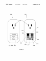
The netWorked device 900 on the left shoWs the look of the
GUI at one point in time Where it alloWs the user to turn the
poWer on/off if a ?rst section 904 of the screen is touched. If
a second section 905 of the screen is touched, the netWorked
device 900 tries to connect to the netWork. And if a third
section 906 of the screen is touched, a second level of menu is
shoWn on the touch sensitive display 903. The vieW of the
netWorked device 901 on the right shoWs the second level of
menu that is used to select the color. Nine different sections
910-918 of the touch sensitive display 903 are created, each
With a different color. Some may have visible symbols as
Well. If the user touches one of the sections 910-918, the color
of that section is taken as the user selected color. A controller
can then convert the information about Which section Was
potentiometer, an optical shaft encoder, a magnetic detector,
tWo-axis hall-effect sensors or other Well-knoWn methods of
detecting the angular position of a disk or shaft.
A cross section of a Wall 709 of the netWorked device
to detect the color being spoken, or a video camera could be
used and a color sample put into the vieW of the video camera.
Any method for the user to enter a color selection could be
used in some embodiments.
FIG. 9 shoWs a netWorked device 900, 901 With a touch
sensitive display 903 used for a graphic user interface (GUI).
ground or left as an open circuit so that as each output is
angular position of the color Wheel could also be used such as
such as individual sWitch outputs for each rotary position, an
analog to digital converter measuring a voltage across a
color chosen to the user. The user may push a button to cycle
betWeen the different colors or a capacitive sensing sWitch or
other proximity or touch device could be used to select a
color. In other embodiment, voice recognition might be used
pull-up resistors and a controller located on the same printed
circuit board (or elseWhere in the netWorked device). In one
embodiment the rotary dip sWitch is an octal encoder that
generates 3 bits of output that can either be connected to
cylindrical element 831. Rotating selector sleeve 835 With a
selector indicator 833 can be rotated about the cylindrical
element 831. Fixed color ring 832 is a?ixed to the cylindrical
element 831 adjacent to the rotating selector sleeve 835.
Selection indicator 833 points at the currently selected color
on the ?xed color sleeve 832. In FIG. 8D the currently
selected color is color “1”, the color of section 834.
green and blue LEDs, or other colored lights to indicate the
rotary dip sWitch 706 Which generates information depending
on the rotational angle of the shaft 705. The information is
then available on the pins 708 (not all pins are shoWn) of the
rotary dip sWitch 706. The pins 708 may be connected to
cylindrical element 821. Selection indicator 823 points at the
currently selected color on the rotating color sleeve 822. The
currently selected color in FIG. 8C is color “3”, the color of
60
shoWs the edge 702 protruding through the Wall and a portion
of the angled side 701 visible through an opening in the Wall
touched to the appropriate color code.
Unless otherWise indicated, all numbers expressing quan
tities of elements, optical characteristic properties, and so
forth used in the speci?cation and claims are to be understood
as being modi?ed in all instances by the term “about.”
Accordingly, unless indicated to the contrary, the numerical
parameters set forth in the preceding speci?cation and
709. Exterior vieW 740 shoWs the outside of the netWorked
device With the Wall 741 having an opening 742. In the posi
attached claims are approximations that can vary depending
make it even clearer Which color is selected, and indicator
upon the desired properties sought to be obtained by those
skilled in the art utiliZing the teachings of the present inven
arroW 743 is included on the Wall 741 pointing at the current
tion. At the very least, and not as an attempt to limit the
tion shoWn, section 713 is ?lling most of opening 742. To help
65
US 8,306,639 B2
11
12
the local control command only if the color selected by
application of the doctrine of equivalents to the scope of the
claims, each numerical parameter should at least be construed
the user is one of the one or more non-locking colors.
in light of the number of reported signi?cant digits and by
applying ordinary rounding techniques. Notwithstanding that
the numerical ranges and parameters setting forth the broad
5
5. The netWorked device of claim 4 in Which the means for
controlling the state of the netWorked device controls an
On/Off state of the netWorked device.
6. A netWorked device comprising:
scope of the invention are approximations, the numerical
values set forth in the speci?c examples are reported as pre
a controller;
cisely as possible. Any numerical value, hoWever, inherently
a netWork adapter communicatively coupled to the control
contains certain errors necessarily resulting from the standard
deviations found in their respective testing measurements.
The recitation of numerical ranges by endpoints includes
all numbers subsumed Within that range (eg 1 to 5 includes
a color selection mechanism communicatively coupled to
the controller, the color selection mechanism alloWing a
ler; and
user to select a color from a plurality of colors, the
plurality of colors having at least one locking color and
1, 1.5, 2, 2.75, 3, 3.80, 4, and 5).
As used in this speci?cation and the appended claims, the
singular forms “a”, “an”, and “the” include plural referents
one or more non-locking colors; Wherein
unless the content clearly dictates otherWise. Thus, for
the color selection mechanism communicates information
corresponding to the color selected by the user to the
example, reference to an element described as “an LED” may
refer to a single LED, tWo LEDs or any other number of
the controller converts the information communicated by
LEDs. As used in this speci?cation and the appended claims,
the term “or” is generally employed in its sense including
“and/or” unless the content clearly dictates otherWise.
As used herein, the term “coupled” includes direct and
indirect connections. Moreover, Where ?rst and second
devices are coupled, intervening devices including active
devices may be located there betWeen.
Any element in a claim that does not explicitly state
“means for” performing a speci?ed function, or “step for”
performing a speci?ed function, is not to be interpreted as a
“means” or “step” clause as speci?ed in 35 U.S.C. §112, 11 6.
In particular the use of “step of” in the claims is not intended
controller;
the color selection mechanism to a color code corre
20
adapter,
the netWork adapter sends the color code out over a net
Work,
25
the netWork adapter receives a message from the netWork
to change a state of the netWorked device and commu
nicates it to the controller, and
the controller changes the state of the netWorked device in
response to the message to change the state of the net
30
to invoke the provision of 35 U.S.C. §112, 11 6.
Worked device communicated by the netWork adapter
only if the color selected by the user is one of the one or
The description of the various embodiments provided
above is illustrative in nature and is not intended to limit the
invention, its application, or uses. Thus, variations that do not
depart from the gist of the invention are intended to be Within
sponding to the color selected by the user,
the controller communicates the color code to the netWork
more non-locking colors.
7. The netWorked device of claim 6 in Which the netWork
utiliZes communication over an AC poWer line.
35
8. The netWorked device of claim 6 in Which the netWork
the scope of the embodiments of the present invention. Such
utiliZes radio frequency communication.
variations are not to be regarded as a departure from the
9. The netWorked device of claim 6 in Which the controller
and the netWork adapter are integrated on a single integrated
circuit.
10. The netWorked device of claim 6 in Which the state of
the netWorked device being controlled is an On/Off state of
the netWorked device.
11. The netWorked device of claim 6 in Which
intended scope of the present invention.
What is claimed is:
1. A netWorked device comprising:
means for controlling a state of the netWorked device;
40
means for connecting to a network;
the netWork adapter receives a status request message over
means for alloWing a user to select a color from a plurality
of colors, the plurality of colors having at least one
45
locking color and one or more non-locking colors; and
means for generating a selected color code corresponding
communicating a response message to the netWork
adapter to send out over the netWork, the controller
to the color selected by the user, each color of the plu
rality of colors having a corresponding color code;
Wherein
the means for connecting to the netWork sends the selected
color code over the netWork; and
the means for controlling the state of the netWorked device
changes the state of the netWorked device in response to
a message from the netWork only if the color selected by
50
55
state of the netWorked device; Wherein
the controller changes the state of the netWorked device in
response to the local control command only if the color
selected by the user is one of the one or more non
locking colors.
60
netWork independent of the color selected by the user.
4. The netWorked device of claim 1 further comprising:
means for alloWing the user enter a local control command;
Wherein
the means for controlling the state of the netWorked device
changes the state of the netWorked device in response to
responding independent of the color selected by the user.
12. The netWorked device of claim 6 further comprising:
a local control interface communicatively coupled to the
controller, the local control interface alloWing the user to
enter a local control command to request a change to the
the user is one of the one or more non-locking colors.
2. The netWorked device of claim 1 in Which the means for
controlling the state of the netWorked device controls an
On/Off state of the netWorked device.
3. The netWorked device of claim 1 in Which the netWorked
device responds to a request for status information from the
the netWork and communicates it to the controller; and
the controller responds to the status request message by
65
13. The netWorked device of claim 12 in Which the state of
the netWorked device to Which the local control command
requests a change is an On/ Off state of the netWorked device.
14. The netWorked device of claim 6 in Which the color
selection mechanism is a graphical user interface.
15. The netWorked device of claim 6, the color selection
mechanism comprising:
an electrical component With a rotatable shaft and an out
put communicatively coupled to the controller; and
US 8,306,639 B2
14
13
a color Wheel having a center, an edge and a colored area,
section color corresponding to the color selected by the
the center of the color Wheel coupled to the rotatable
shaft of the electrical component and the colored area
divided into sections, each section imprinted With a sec
19. The netWorked device of claim 15 further comprising
tion color selected from the plurality of colors; such that
as the color Wheel is rotated by user manipulation of the
edge, the colored area of the color Wheel and the rotat
able shaft of the electrical component also rotate; and
the output of the electrical component With a rotatable shaft
communicates current rotational position information
corresponding to the color selected by the user to the
controller.
16. The netWorked device of claim 15 Wherein the electri
cal component With a rotatable shaft is a rotary sWitch.
17. The netWorked device of claim 15 Wherein the electri
cal component With a rotatable shaft is a potentiometer and
the controller further comprising an analog to digital con
user at the current rotational position.
5
a portion of the edge of the color Wheel protrudes from
the outer housing of the netWorked device, Whereby
10
of the potentiometer rotates.
18. The netWorked device of claim 15, the color selection
mechanism further comprising:
a selection mark in close physical proximity to the section
of the colored area of the color Wheel imprinted With the
the user is able to manipulate the edge to rotate the
color Wheel about its center;
a portion of the colored area is visible through the aper
ture in the outer housing of the netWorked device; and
a majority of the portion of the colored area visible
through the aperture in the outer housing of the net
Worked device is the section of the colored area
imprinted With the section color corresponding to the
color code selected by the user at the current rota
tional position.
20. The netWorked device of claim 15 in Which at least one
section of the colored area is also imprinted With a visible
verter, the input of the analog to digital converter electrically
connected to a voltage divider circuit that changes as the shaft
an outer housing With an aperture; Wherein
the color Wheel is mounted in the netWorked device so that,
20
symbol.
21. The netWorked device of claim 15 in Which at least one
section of the colored area has a tactilely recogniZable sym
bol.