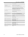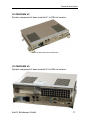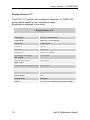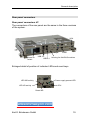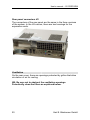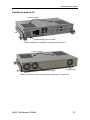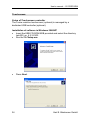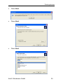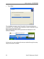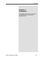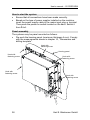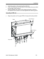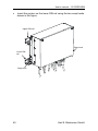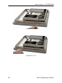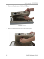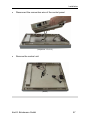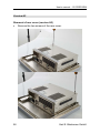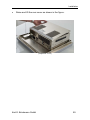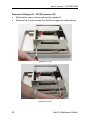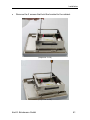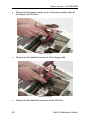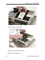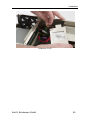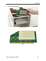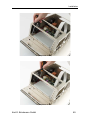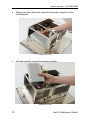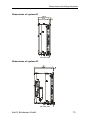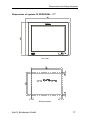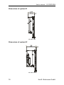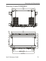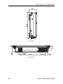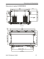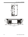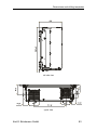
1
COMBICONTROL
C6
GB Instruction Manual
PERFORM IPC‘s
12.1“…17“
Mat.No.
00C6NEB-AB00
Rev.
1B
The information in this manual is subject to change and is in no way binding upon KEB (Karl E. Brinkmann GmbH).
KEB is not responsible for technical errors or other omissions in the manual, and shall not accept any
responsibility deriving from its use.
All brands and product names mentioned in this manual are trade-marks of their respective owners.
The products of the familiy C6 ECON are compliant with European Directive 2004/108/EC concerning
electromagnetic compatibility and Directive 2006/95/EC concerning the safety of electrical products,
and subsequent variations.
Instructions on disposal
Summary
Chapter 1 Preliminary operations ......................................................5
List of material provided..................................................................6
Prior to installation...........................................................................6
Notes on the guarantee ..................................................................6
Chapter 2 General description...........................................................7
Presentation ....................................................................................8
General technical specifications .....................................................9
C6 PERFORM H1 .....................................................................11
C6 PERFORM H3 .....................................................................11
C6 PERFORM ...........................................................................12
Options H1 H3...............................................................................13
Options H1.................................................................................13
Options H3.................................................................................13
Front panel C6 PERFORM ...........................................................14
Display ..........................................................................................15
Display quality TFT-LCD ...........................................................15
Display features 12.1” ...............................................................16
Display features 15.0” ...............................................................17
Display features 17”...................................................................18
Rear panel connectors..................................................................19
Rear panel connectors H1.........................................................19
Rear panel connectors H3.........................................................20
Ventilation .....................................................................................20
Ventilation module H1 ...............................................................21
Ventilation module H3 ...............................................................22
Procedure for cleaning fan filters H1 .........................................23
Procedure for cleaning fan filters H3 .........................................26
Characteristics of power suppliers ................................................30
Magnetic units ...............................................................................31
H1 ..............................................................................................31
H3 ..............................................................................................31
Compact Flash ..........................................................................32
Chapter 3 Pointing devices..............................................................33
Touchscreen .................................................................................34
Setup of Touchscreen controller ...............................................34
Installation of software in Windows 2000/XP ............................34
Chapter 4 Installation.......................................................................37
How to start the system ................................................................38
Panel assembly.............................................................................38
Assembly of DIN rail......................................................................39
Access to internal parts.................................................................41
Version H1 ....................................................................................41
Removal of rear cover (version H1) ..........................................41
Removal of hard disk (version H1) ............................................43
Removal of RAM (version H1-H3).............................................45
Removal of heatsink (version H1) .............................................46
Removal of microprocessor (version H1) ..................................47
Removal of power supplier (version H1) ...................................48
Removal of front panel (Versions H1, H3) ................................51
Version H3 ....................................................................................58
Removal of rear cover (version H3) ..........................................58
Removal of floppy kit - CD HD (version H3)..............................60
Removal of Hd 2.5” (Version H3) ..............................................63
Removal of backplane (H3).......................................................66
Removal of power supplier........................................................68
Chapter 5 Dimensions and drilling templates...................................71
Dimensions of system C6 PERFORM – 12.1” ..........................72
Dimensions of system H1 ......................................................73
Dimensions of system H3 ......................................................73
Dimensions of system C6 PERFORM - 15” .............................74
Dimensions of system H1 ......................................................75
Dimensions of system H3 ......................................................75
Dimensions of system C6 PERFORM -- 17”.............................77
Dimensions of system H1 ......................................................78
Dimensions of system H3 ......................................................78
Dimensions of system C6 PERFORM H1 .................................79
Dimensions of system C6 PERFORM H3 .................................81
Chapter 6 Connectors pin-out ..........................................................84
Parallel port connector ..................................................................85
Keyboard connector PS/2 .............................................................85
Serial interface connector DB9 .....................................................86
Mouse connector PS/2..................................................................86
Serial interface connector DB15 ...................................................87
USB connector type A...................................................................87
VGA connector..............................................................................88
RJ45 ETHERNET connector ........................................................88
Preliminary operations
Chapter 1
Preliminary operations
This chapter contains the list of material
included in the packing box.
Karl E. Brinkmann GmbH
5
User's manual – C6 PERFORM
List of material provided
The following is a list of the material included in the packaging:
•
•
•
•
•
•
•
System.
Lateral modules (optional).
Pointing modules (optional).
Power cable.
User's Guide
Support disks.
Document with "Conditions of Guarantee" (keep for any future
repair work).
On request:
•
Operating system kit (pre-loaded software, license for use,
manual and optical/magnetic supports).
Prior to installation
After you have checked the contents of the package, you should
keep the packing materials as they may be needed for transporting
the system in the future.
After unpacking the system, place all of the material on a work
surface and carefully follow the instructions set forth in the following
chapters.
Notes on the guarantee
The guarantee is regulated by the document "Conditions of
Guarantee" which is provided with the system.
6
Karl E. Brinkmann GmbH
General description
Chapter 2
General description
This chapter describes the general
features of the systems.
Karl E. Brinkmann GmbH
7
User's manual – C6 PERFORM
Presentation
KEB PERFORM is an industrial PC for panel installation. It offers
substantial scalability in terms of performance, functionality and
configurations. The plastic front includes an LCD cartridge. This
reduces the volume in depth of the rear module, which is available in
the formats H1 and H3. The display can be 12.1", 15" or 17", also
with touch screen. On the front panel, with degree of protection IP65,
there are two USB ports protected by rubber closures.
8
Karl E. Brinkmann GmbH
General description
General technical specifications
Front panel protection
Input devices
LCD display
External keyboard interface
External mouse interface
Motherboard
Processor
RAM
Video RAM
IDE Interface for mass
memories
SATA Interface for mass
memories
BIOS
Video sub-system
Analogue video interface
CRT
LCD internal interface
IP65
Alphanumerical keyboard (version TE)
Touchscreen (optional)
TouchPAD (optional)
Trackball (optional)
Colours TFT SVGA 12.1” 350 cd/m2 – 2 x CCFL
Colours TFT XVGA 15.0” 450 cd/m2 – 4 x CCFL
Colours TFT XVGA 15.0” 300 cd/m2 – 4 x CCFL
Minidin PS/2
Minidin PS/2
ASEM CPU 1021
Intel Celeron M, Core 2 DUO up to 2.4 GHz
512 MB – 4GB (2 x SODIMM 200pin DDR2 PC5300
low profile)
Shared with system RAM up to 256MB
1 bus Fast IDE, integrated on motherboard
3 bus SATA 2 – 3Gb/s, integrated on motherboard
On Flash EPROM of 2Mbit
Integrated, based on Intel GMA X3100. Supports
acceleration 2D/3D, DirectX and OpenGL.
Analogue video output on connector SUBD-H15,
compatible VGA, SVGA, XGA, SXGA.
Digital LVDS (for internal connection)
Resolution / colours
12.1”: 800 x 600 / 16 M/colours
15.0”: 1024 x 768 / 16 M/colours
17.0”: 1280 x 1024 / 16 M/colours
Floppy disk controller
Parallel port
Serial ports
Integrated on motherboard
1 optional configurable in modes SPP, ECP, EPP
2 integrated: 2 x RS232
Optional: 1 x RS232 / RS422 / RS485 also
optoisolated
Type PS/2
4 ports on rear panel
2 ports on front panel (WS and FT)
1 port 10/100Mbps based on Intel 82551QM
1 port 10/100Mbps based on Intel 82562V
2 free PCI slots in H3 models
3 PCI slot and 1 PCI-Express x4, free in H4 models
1 PCI slot and 1 PCI-Express x4, free in H3 models
2 PCI slot, 1 PCI-Express x1 and 1 PCI-Express x4,
Mouse and keyboard ports
USB
Local network
Expansion bus
Karl E. Brinkmann GmbH
9
User's manual – C6 PERFORM
Silicon Disk
Touchscreen
Touchscreen controller
Watch-dog
Hardware monitor
Reset CPU
Power supply
free in H4 models
Compact flash connector integrated on board
Resistive with 5 wires (optional)
Optional, on-board integrated controller
integrated on motherboard, with manual reset button
Allows monitoring of the temperature of the
microprocessor and of the card, of the supply
voltages and of the speed of the tachometric fans.
Checks lighting of an alarm LED.
Push button present on rear panel
100 ÷ 220 V/AC (autoranging) 140W
18÷36V/DC, 140W
Relative humidity
Maximum 80% without condensation
Storage temperature
From - 20°C to + 60°C
Operating temperature
from + 0°C to + 50°C diskless or with C.F.
from + 0°C to + 45°C with magnetic units
Dimensions
See Chapter 10 Dimensions and drilling templates.
Weight C6 PERFORM
H1 4.8 Kg
H3 6.4 Kg
Weight C6 PERFORM 12” H1 Standard version 8.9 Kg
Version 12.4 Kg
Weight C6 PERFORM 12” H3 Standard version 10.5 Kg
Version 14.0 Kg
Weight C6 PERFORM 15” H1 Standard version 8.9 Kg
Version 12.4 Kg
Weight C6 PERFORM 15” H3 Standard version 10.5 Kg
Version 14.0 Kg
Weight C6 PERFORM 17” H1 Standard version 8.9 Kg
Version 12.4 Kg
Weight C6 PERFORM 17” H3 Standard version 10.5 Kg
Version 14.0 Kg
Weight PB550
4.8 Kg
10
Karl E. Brinkmann GmbH
General description
C6 PERFORM H1
System composed of base module H1 in DIN rail version.
Detail of rear panel and connectors
C6 PERFORM H3
System composed of base module H3 in DIN rail version.
Karl E. Brinkmann GmbH
11
User's manual – C6 PERFORM
Detail of rear panel and connectors
C6 PERFORM
This system is composed of the base module which may be:
•
•
H1
H3
Each of these version can be equipped with a display of 12.1”, 15.0”
or 17.0”.
C6 PERFORM
12
Karl E. Brinkmann GmbH
General description
Options H1 H3
Options H1
Options
Power supply
Floppy disk (front access)
CD-ROM or CD-RW (front
access)
Touch-screen
Additional serial ports
C6 PERFORM H1
18÷24 V/DC
No
No
Resistive 5 wires
serial port RS-232/422/485
(also optoisolated)
Options H3
Options
Power supply
Hard disk
Floppy disk (internal access)
CD-ROM or CD-RW (internal
access)
Floppy disk (front access)
CD-ROM or CD-RW (front
access)
Touch-screen
Additional serial ports
Ethernet ports
Fieldbus embedded
Free expansion slots
Karl E. Brinkmann GmbH
C6 PERFORM H3
18÷24 V/DC
3,5”
3.5" or 3.5 slim
5.25" slim
No
3.5" slim
No
5.25" slim
Resistive 5 wires
serial port RS-232/422/485 (also optoisolated)
1 x 10/100 Mbps and 1 x 10/100/1000 Mbps
1 x NETcore®
1 PCI and 1 PCI-Express
13
User's manual – C6 PERFORM
Front panel C6 PERFORM
The front is made from aluminium with a thickness of 6mm. Its
degree of protection is IP65. The rear body is made of nickel plated
steel sheet metal to ensure electromagnetic shielding in order to
resolve issues of EMI and RFI.
LCD display
Aluminium front
panel
USB ports
System
status
information
LCD
Detail of front panel FT
LED network
LED hard disk activity
LED power on
LED alarm for fan
shutdown /
temperature.
Detail of LED for information on system status
14
Karl E. Brinkmann GmbH
General description
Display
The front panel of the WS systems includes a backlit LCD module.
The display may be:
•
•
•
12.1” TFT (2 lamps) with a resolution of 800 x 600 pixels.
15.0” TFT (4 lamps) with a resolution of 1024 x 768 pixels.
17.0” TFT (4 lamps) with a resolution of 1280 x 1024.
The display unit is installed in a cartridge that contains all the unit's
control and power supply devices.
Display quality TFT-LCD
The LCDs may have defective pixels (always on or always off).
The unique manufacturing process of the LCD panels does however
keep the defect rate very low, considering the high number of
elements of the RGB triad on the panel. The maximum admissible
number or defects is stated by the manufacturer and is shown in the
following table.
LCD panel
12.1”
15”
17”
Maximum
Maximum
admissible
admissible
number of pixels number of pixels
on
off
10
10
6
7
3
5
Karl E. Brinkmann GmbH
Maximum admissible
number of defective
pixels (on+off)
15
10
5
15
User's manual – C6 PERFORM
Display features 12.1”
The LCD 12.1” module has a maximum resolution of 800x600, active
matrix backlit by two fluorescent lamps
Brightness is adjusted in the setup.
Display features 12.1”
Dimensions
12.1”
Technology
LCD-TFT active matrix
Visible area
246 (A) x 184.5 (L) mm
Resolution
800 x 600
Colours
16M
Dot Pitch
0.3075 mm
Brightness
350 cd / m² typical
Horizontal visual angle
(left + right)
140° typical
Vertical visual angle
(high + low)
120° typical
Contrast value on optimal angle
550:1
typical
50 ms maximum
Response (decay)
50 ms maximum
Power supply
3.3 V
Surface finish
Anti-glare
Operating temperature
0 ÷ 50 °C
Backlit
Two CCFL (Cold Cathode Fluorescent Lamp)
Weight
750 g.
16
Karl E. Brinkmann GmbH
General description
Display features 15.0”
The LCD 15.0” module has a maximum resolution of 1024x768,
active matrix backlit by four fluorescent lamps
Brightness is adjusted in the setup.
Display features 15.0”
Dimensions
15,0”
Technology
LCD-TFT active matrix
Visible area
304.1 (A) x 228.1 (L) mm
Resolution
1024 x 768
Colours
16M
Dot Pitch
0.297 mm
Brightness
450 cd / m² typical
Horizontal visual angle
(left + right)
160° typical
Vertical visual angle
(high + low)
155°, typical
Contrast value on optimal angle
450:1 typical
Response (Rise)
10 ms maximum
Power supply
3.3 V
Surface finish
Anti-glare
Backlit
4 CCFL (Cold Cathode Fluorescent Lamp)
Life cycle of lamps
50000 hours
Karl E. Brinkmann GmbH
17
User's manual – C6 PERFORM
Display features 17”
The LCD 17.0” module has a maximum resolution of 1280x1024,
active matrix backlit by four fluorescent lamps.
Brightness is adjusted in the setup.
Display features 17.0”
Dimensions
17,0”
Technology
LCD-TFT active matrix
Visible area
338.0 (L) x 270.0 (A) mm
Resolution
1280 x 1024
Colours
16.2 M
Dot Pitch
0.264 mm
Brightness
300 cd / m² typical
Horizontal visual angle
(left + right)
150° typical
Vertical visual angle
(high + low)
135° typical
Contrast value on optimal angle
500:1 typical
Response (Rise)
10 ms typical
Response (decay)
24 ms typical
Power supply
5V
Surface finish
Anti-glare
Backlit
4 CCFL (Cold Cathode Fluorescent Lamp)
18
Karl E. Brinkmann GmbH
General description
Rear panel connectors
Rear panel connectors H1
The connectors of the rear panel are the same in the three versions
of the system.
Lan1
Lan2
Power supply
input
DVI
Mouse
Keyb
USB 2-3
Power on
switch
VGA
COM2
COM1
Housing for field BUS modules
USB 0-1
Enlarged detail of position of indicator LEDs and reset keys.
Power supply present LED
LED WD activity
Reset CPU
LED HD activity
Reset WD
Karl E. Brinkmann GmbH
19
User's manual – C6 PERFORM
Rear panel connectors H3
The connectors of the rear panel are the same in the three versions
of the system. In the H3 version, there are two housings for the
expansion cards.
Expansion slots
Expansion slots
Ventilation
On the rear cover, there are openings protected by grilles that allow
circulation of air for cooling.
NB: Be sure not to obstruct the ventilation openings.
Periodically clean the filters as explained below.
20
Karl E. Brinkmann GmbH
General description
Ventilation module H1
Cool air intake
Power supply hot air outlet
Detail of position of ventilation openings on module H1
Cool air intake
Hot air outlet
Hot air outlet
Detail of position of fans and ventilation openings on module H1
Karl E. Brinkmann GmbH
21
User's manual – C6 PERFORM
Ventilation module H3
Cool air intake
Cool air intake
Power supplier hot air outlet
Detail of position of ventilation openings on module H3
Cool air intake
Hot air outlet
Detail of position of fans and ventilation openings on module H3
22
Karl E. Brinkmann GmbH
General description
Procedure for cleaning fan filters H1
•
Remove the screws of the rear cover of the system as shown in
the figure.
(sequence 1 of 6)
(sequence 2 of 6)
•
Raise and lift the rear cover as shown in the figure.
Karl E. Brinkmann GmbH
23
User's manual – C6 PERFORM
(sequence 3 of 6)
•
Remove the anchoring screws of the filter bracket.
(sequence 4 of 6)
•
24
Remove the filter bracket.
Karl E. Brinkmann GmbH
General description
(sequence 5 of 6)
•
Remove the filter.
(sequence 6 of 6)
Karl E. Brinkmann GmbH
25
User's manual – C6 PERFORM
Procedure for cleaning fan filters H3
•
Remove the screws of the support grille of the filter.
(sequence 1 of 7)
•
Remove the anti-flame grille and the filter
(sequence 2 of 7)
26
Karl E. Brinkmann GmbH
General description
Filter bracket
Filter
Anti-flame net
(detail)
•
Remove the screws of the rear cover of the system as shown in
the figure.
(sequence 4 of 7)
•
•
Raise and lift the rear cover as shown in the figure.
Remove the screws of the support grille of the filter as shown in
the figure.
Karl E. Brinkmann GmbH
27
User's manual – C6 PERFORM
(sequence 5 of 7)
•
Remove the support grille of the filter as shown in the figure.
(sequence 6 of 7)
28
Karl E. Brinkmann GmbH
General description
•
Remove the filter.
(sequence 7 of 7)
Filter
Filter bracket
(detail)
Karl E. Brinkmann GmbH
29
User's manual – C6 PERFORM
Characteristics of power suppliers
The systems may include two types of power suppliers: with AC
(mains) input and with DC input.
Power supplier with AC
input
Power supplier with DC
input
Input voltage
100 – 240 V (max. 185W)
19 – 32 V (max. 200W)
Output voltages
± 5 / ± 12 / + 3.3
± 5 / ± 12 / + 3.3
Dimensions (D x L x H)
190 x 100 x 40.5
190 x 100 x 40.5
Power on switch
AC input
Detail of power supplier with AC input
DC power supply
terminal
Detail of power supplier with DC input
30
Karl E. Brinkmann GmbH
General description
Magnetic units
The system, in its various versions may optionally and in some case
alternatively include the following magnetic units:
H1
Hard disk 2.5”
Detail of magnetic units version H1
H3
Floppy / CD Slim / Hd 3.5” kit
Floppy disk kit
Hard disk 2.5”
Floppy CD slim kit
Compact Flash
Detail of magnetic units version H4
Karl E. Brinkmann GmbH
31
User's manual – C6 PERFORM
Compact Flash
The Compact Flash modules can be configured as master or slave
by means of a jumper on the card that houses their connector (see
“Chapter 6 Hardware Setup” paragraph “Compact Flash”)
Detail of Compact Flash module
32
Karl E. Brinkmann GmbH
Pointing devices
Chapter 3
Pointing devices
This chapter describes the procedure
for calibrating the monitors with
analogue input.
Karl E. Brinkmann GmbH
33
User's manual – C6 PERFORM
Touchscreen
Setup of Touchscreen controller
The 5-wire resistive touchscreen (optional) is managed by a
dedicated USB controller (optional).
Installation of software in Windows 2000/XP
• Insert the KEB CD-ROM KEB provided and select the directory
\win200_xp_4.2.3.2303.
• Run the file Setup.exe.
•
34
Press Next.
Karl E. Brinkmann GmbH
Pointing devices
•
Press Next.
•
Press Next.
•
Press Next.
Karl E. Brinkmann GmbH
35
User's manual – C6 PERFORM
•
Press Next.
The installation program scans the system for any serial devices
connected. If so, a window opens asking to confirm installation of the
driver for this new device found.
After installing the driver will be generated and displayed on the
desktop a shortcut.
At this point you can configure the device installed through the setup
utility on the menu TouchKit
36
Karl E. Brinkmann GmbH
Installation
Chapter 4
Installation
This chapter describes the procedure
for calibrating the monitors with
analogue input.
Karl E. Brinkmann GmbH
37
User's manual – C6 PERFORM
How to start the system
•
•
Ensure that all connections have been made correctly.
Based on the type of power supplier installed on the machine,
insert the power supply cable in the mains input plug or terminal.
Then press the power on switch located on the back. Switch it
from O to I.
Panel assembly
The systems may be panel mounted as follows:
• Pre-work the housing panel (maximum thickness 4 mm). Comply
with the measurements shown in chapter 10, "Dimensions and
drilling template".
Hook with
fastening screw
Housing panel
Hook with
fastening screw
Hook with
fastening screw
Hook with
fastening screw
Hook with
fastening screw
38
Karl E. Brinkmann GmbH
Installation
•
•
•
Insert the system in the opening thus obtained.
Insert the fastening hooks provided in the proper places provided
on the body of the machine.
Carefully tighten the screws of the fastening hooks so that the
front panel of the monitor is secured against the fastening panel.
Assembly of DIN rail
•
Hang the system on the upper DIN rail using the bend provided.
Upper DIN rail
Bend
Lower DIN rail
Snap hook
Snap hook
Karl E. Brinkmann GmbH
39
User's manual – C6 PERFORM
•
Insert the system on the lower DIN rail using the two snap hooks
shown in the figure.
Upper DIN rail
Snap hook
Lower DIN
rail
Snap hook
40
Karl E. Brinkmann GmbH
Installation
Access to internal parts
The operations described below must only be performed by qualified
personnel.
• Shut down the system.
• Disconnect the power cable.
• Set the system on a surface. Use care not to damage the front
panel.
Version H1
Removal of rear cover (version H1)
•
Remove the two screws of the rear cover.
(sequence 1 of 3)
Karl E. Brinkmann GmbH
41
User's manual – C6 PERFORM
(sequence 2 of 3)
•
Raise and lift the rear cover as shown in the figure.
(sequence 3 of 3)
42
Karl E. Brinkmann GmbH
Installation
Removal of hard disk (version H1)
•
Remove the 3 screws that hold the bracket to the system.
(sequence 1 of 4)
(sequence 2 of 4)
•
Disconnect the data flat connector from the hard disk.
Karl E. Brinkmann GmbH
43
User's manual – C6 PERFORM
•
(sequence 3 of 4)
Disconnect the power supply to the hard disk
(sequence 4 of 4)
44
Karl E. Brinkmann GmbH
Installation
Removal of RAM (version H1-H3)
•
Expel the module by slightly opening the side fastening tabs of
the plinth.
(sequence 1 of 1)
For re-insertion, check the correct polarity of the module. When
insertion is complete, check for proper closure of the side fastening
tabs.
Karl E. Brinkmann GmbH
45
User's manual – C6 PERFORM
Removal of heatsink (version H1)
•
Loosen the four screws that hold the heatsink.
•
Remove the heatsink
(sequence 1 of 2)
(sequence 2 of 2)
46
Karl E. Brinkmann GmbH
Installation
Removal of microprocessor (version H1)
(sequence 1 of 2)
(sequence 2 of 2)
Karl E. Brinkmann GmbH
47
User's manual – C6 PERFORM
Removal of power supplier (version H1)
•
Remove the two screws that hold the power supplier to the lower
panel of the system.
(sequence 1 of 6)
48
Karl E. Brinkmann GmbH
Installation
•
(sequence 2 of 6)
Remove the two screws that hold the power supplier to the rear
panel of the system.
(sequence 3 of 6)
(sequence 4 of 6)
Karl E. Brinkmann GmbH
49
User's manual – C6 PERFORM
•
Remove the power cable.
•
Extract the power supplier.
(sequence 5 of 6)
(sequence 6 of 6)
50
Karl E. Brinkmann GmbH
Installation
Removal of front panel (Versions H1, H3)
•
Remove the four screws that hold the video cartridge to the rest
of the system.
(sequence 1 of 13)
(sequence 2 of 13)
Karl E. Brinkmann GmbH
51
User's manual – C6 PERFORM
(sequence 3 of 13)
(sequence 4 of 13)
52
Karl E. Brinkmann GmbH
Installation
•
Remove the two screws of the rear cover.
(sequence 5 of 13)
(sequence 6 of 13)
Karl E. Brinkmann GmbH
53
User's manual – C6 PERFORM
•
Remove the rear cover
(sequence 7 of 13)
•
Disconnect the inverter cable.
(sequence 8 of 13)
54
Karl E. Brinkmann GmbH
Installation
•
Gently lift the body of the machine.
(sequence 9 of 13)
•
Disconnect the LCD cable.
(sequence 10 of 13)
Karl E. Brinkmann GmbH
55
User's manual – C6 PERFORM
•
Disconnect the two wires of the front USB port.
(sequence 11 of 13)
•
Disconnect the connection wire of the control panel.
(sequence 12 of 13)
56
Karl E. Brinkmann GmbH
Installation
•
Disconnect the connection wire of the control panel.
(sequence 13 of 13)
•
Remove the central unit.
(detail)
Karl E. Brinkmann GmbH
57
User's manual – C6 PERFORM
Version H3
Removal of rear cover (version H3)
• Remove the two screws of the rear cover.
58
Karl E. Brinkmann GmbH
Installation
•
Raise and lift the rear cover as shown in the figure.
(sequence 3 of 3)
Karl E. Brinkmann GmbH
59
User's manual – C6 PERFORM
Removal of floppy kit - CD HD (version H3)
•
•
Remove the rear cover as previously explained.
Remove the 2 side screws that hold the magnetic-optical group.
(sequence 1 of 6)
(sequence 2 of 6)
60
Karl E. Brinkmann GmbH
Installation
•
Remove the 2 screws that hold the bracket to the cabinet.
(sequence 3 of 6)
(sequence 4 of 6)
Karl E. Brinkmann GmbH
61
User's manual – C6 PERFORM
•
Disconnect the power supply wire of the power supply plate of
the floppy and CD-Rom.
(sequence 5 of 6)
•
Disconnect the data flat connector of the floppy disk.
(sequence 6 of 6)
•
62
Disconnect the data flat connector of the CD-Rom.
Karl E. Brinkmann GmbH
Installation
Removal of Hd 2.5” (Version H3)
•
Remove the two external screws that hold the bracket to the
body.
(sequence 1 of 5)
(sequence 2 of 5)
•
Remove the internal screw that holds the bracket to the body.
Karl E. Brinkmann GmbH
63
User's manual – C6 PERFORM
(sequence 3 of 5)
•
Carefully extract the hard disk.
(sequence 4 of 5)
•
Disconnect the data flat connector.
•
Disconnect the power wire.
64
Karl E. Brinkmann GmbH
Installation
(sequence 5 of 5)
Karl E. Brinkmann GmbH
65
User's manual – C6 PERFORM
Removal of backplane (H3)
•
Remove the screws that hold the backplane to the body.
(sequence 1 of 3)
(sequence 2 of 3)
66
Karl E. Brinkmann GmbH
Installation
•
Extract the backplane.
(sequence 3 of 3)
(detail)
Karl E. Brinkmann GmbH
67
User's manual – C6 PERFORM
Removal of power supplier
•
•
Remove the rear cover as previously described.
Remove the two external screws that hold the power supplier.
(sequence 1 of 6)
(sequence 2 of 6)
•
68
Remove the two internal screws that hold the power supplier.
Karl E. Brinkmann GmbH
Installation
(sequence 3 of 6)
(sequence 4 of 6
Karl E. Brinkmann GmbH
69
User's manual – C6 PERFORM
•
Disconnect the cable that connects the power supplier to the
motherboard.
(sequence 5 of 6)
•
Lift and carefully extract the power supplier.
(sequence 6 of 6)
70
Karl E. Brinkmann GmbH
Dimensions and drilling templates
Chapter 5
Dimensions and drilling
templates
This chapter describes the dimensions
and drilling templates of the systems.
Karl E. Brinkmann GmbH
71
User's manual – C6 PERFORM
Dimensions of system C6 PERFORM – 12.1”
front view
drilling template
72
Karl E. Brinkmann GmbH
Dimensions and drilling templates
Dimensions of system H1
left side view
Dimensions of system H3
left side view
Karl E. Brinkmann GmbH
73
User's manual – C6 PERFORM
Dimensions of system C6 PERFORM - 15”
front view
drilling template
74
Karl E. Brinkmann GmbH
Dimensions and drilling templates
Dimensions of system H1
left side view
Dimensions of system H3
left side view
Karl E. Brinkmann GmbH
75
User's manual – C6 PERFORM
drilling template
76
Karl E. Brinkmann GmbH
Dimensions and drilling templates
Dimensions of system C6 PERFORM -- 17”
front view
drilling template
Karl E. Brinkmann GmbH
77
User's manual – C6 PERFORM
Dimensions of system H1
left side view
Dimensions of system H3
left side view
78
Karl E. Brinkmann GmbH
Dimensions and drilling templates
Dimensions of system C6 PERFORM H1
front view
Rear view
Karl E. Brinkmann GmbH
79
User's manual – C6 PERFORM
rear view
upper view
80
Karl E. Brinkmann GmbH
Dimensions and drilling templates
Dimensions of system C6 PERFORM H3
rear view
front view
Karl E. Brinkmann GmbH
81
User's manual – C6 PERFORM
left side view
upper view
82
Karl E. Brinkmann GmbH
Dimensions and drilling templates
left side view
upper view
Karl E. Brinkmann GmbH
83
User's manual – C6 PERFORM
Chapter 6
Connectors pin-out
This attachment describes the pin-out
of the KEB standard connectors
included on the external panel of the
systems.
•
•
•
•
•
•
84
Parallel port connector
(DB25F).
Serial port connectors
(DB9M, DB15M).
Mouse connector PS/2 (mini-Din).
Keyboard connector PS/2 (miniDin).
USB connector type A (USBF).
VGA connector (DB15F HD).
Karl E. Brinkmann GmbH
Connectors
Parallel port connector
PIN
1
2
3
4
5
6
7
8
9
10
11
12
13
SIGNAL
Strobe/
Data 0
Data 1
Data 2
Data 3
Data 4
Data 5
Data 6
Data 7
Ack/
Busy
Paper End
Select
PIN
14
15
16
17
18
19
20
21
22
23
24
25
SIGNAL
Auto Feed/
Error/
Initialize Printer/
Select Input/
Ground
Ground
Ground
Ground
Ground
Ground
Ground
Ground
Keyboard connector PS/2
The PS/2 keyboard connector is a female mini-din connector.
PIN
1
2-6
3
4
5
SIGNAL
Keyboard Data
N.C.
Ground
Keyboard Power Supply (+ 5 V DC)
Keyboard Clock
Karl E. Brinkmann GmbH
85
User's manual – C6 PERFORM
Serial interface connector DB9
PIN
1
2
3
4
5
SIGNAL
Carrier Detect
Receive Data (RS-232)
Transmit Data (RS-232)
D.Terminal Ready
Gnd (Mass)
6
7
8
9
Data Set Ready
Request To Send
Clear To Send
Ring Indicator
I/O
INPUT
INPUT
OUTPUT
OUTPUT
⎯⎯
INPUT
OUTPUT
INPUT
INPUT
Mouse connector PS/2
The PS/2 mouse connector is a female mini-din connector.
PIN
1
2-6
3
4
5
86
SIGNAL
Mouse Data
N.C.
Ground
Mouse Power Supply
Mouse Clock
Karl E. Brinkmann GmbH
Connectors
Serial interface connector DB15
PIN
1
SIGNAL
Shield Gnd
2
3
4
5
6
7
Transmit Data (RS-232)
Receive Data (RS-232)
Request To Send
Clear To Send
Data Set Ready
Ground
8
9
10
Data Terminal Ready
Carrier Detect
Transmit Data +/Receive Data +
(RS-485/RS-422)
Transmit Data -/Receive Data (RS-485/RS-422)
Ring Indication (RS-232)
Receive Data + (RS-422)
Receive Data - (RS-422)
N.C.
11
12
13
14
15
I/O
⎯
OUT
IN
OUT
IN
IN
⎯
IN
IN
I/O
I/O
IN
IN
IN
N.C.
USB connector type A
The following is the pin-out of the USB connector type A.
PIN
1
2
3
4
SIGNAL
+ 5 V DC
USB Data USB Data +
Ground
Karl E. Brinkmann GmbH
87
User's manual – C6 PERFORM
VGA connector
The VGA connector is a 15 pin high-density female connector.
PIN
1
2
3
4 - 15
5
6
7
8
9
10
11 - 12
13
14
FUNCTION
Red
Green
Blue
N.C.
Earth
Earth (Red)
Earth (Green)
Earth (Blue)
Earth (not used)
Synchronisms earth
Reserved
Horizontal synchronism
Vertical synchronism
RJ45 ETHERNET connector
88
PIN
Signal
PIN
Signal
1
TX+
5
N.C.
2
TX-
6
RX-
3
RX+
7
N.C.
4
N.C.
8
N.C.
Karl E. Brinkmann GmbH
Karl E. Brinkmann GmbH
Försterweg 36-38 • D-32683 Barntrup
fon: +49 5263 401-0 • fax: +49 5263 401-116
net: www.keb.de • mail: [email protected]
KEB worldwide…
KEB Antriebstechnik Austria GmbH
Ritzstraße 8 • A-4614 Marchtrenk
fon: +43 7243 53586-0 • fax: +43 7243 53586-21
net: www.keb.at • mail: [email protected]
KEB Antriebstechnik
Herenveld 2 • B-9500 Geraadsbergen
fon: +32 5443 7860 • fax: +32 5443 7898
mail: [email protected]
KEB Power Transmission Technology (Shanghai) Co.,Ltd.
No. 435 QianPu Road, Songjiang East Industrial Zone,
CHN-201611 Shanghai, P.R. China
fon: +86 21 37746688 • fax: +86 21 37746600
net: www.keb.cn • mail: [email protected]
KEB Antriebstechnik Austria GmbH
Organizační složka
K. Weise 1675/5 • CZ-370 04 České Budějovice
fon: +420 387 699 111 • fax: +420 387 699 119
net: www.keb.cz • mail: [email protected]
KEB Antriebstechnik GmbH
Wildbacher Str. 5 • D–08289 Schneeberg
fon: +49 3772 67-0 • fax: +49 3772 67-281
mail: [email protected]
KEB España
C/ Mitjer, Nave 8 - Pol. Ind. LA MASIA
E-08798 Sant Cugat Sesgarrigues (Barcelona)
fon: +34 93 897 0268 • fax: +34 93 899 2035
mail: [email protected]
Société Française KEB
Z.I. de la Croix St. Nicolas • 14, rue Gustave Eiffel
F-94510 LA QUEUE EN BRIE
fon: +33 1 49620101 • fax: +33 1 45767495
net: www.keb.fr • mail: [email protected]
KEB (UK) Ltd.
6 Chieftain Buisiness Park, Morris Close
Park Farm, Wellingborough GB-Northants, NN8 6 XF
fon: +44 1933 402220 • fax: +44 1933 400724
net: www.keb-uk.co.uk • mail: [email protected]
KEB Italia S.r.l.
Via Newton, 2 • I-20019 Settimo Milanese (Milano)
fon: +39 02 33535311 • fax: +39 02 33500790
net: www.keb.it • mail: [email protected]
KEB Japan Ltd.
15–16, 2–Chome, Takanawa Minato-ku
J–Tokyo 108-0074
fon: +81 33 445-8515 • fax: +81 33 445-8215
mail: [email protected]
KEB Korea Seoul
Room 1709, 415 Missy 2000
725 Su Seo Dong, Gang Nam Gu
ROK-135-757 Seoul/South Korea
fon: +82 2 6253 6771 • fax: +82 2 6253 6770
mail: [email protected]
KEB RUS Ltd.
Lesnaya Str. House 30, Dzerzhinsky (MO)
RUS-140091 Moscow region
fon: +7 495 550 8367 • fax: +7 495 632 0217
net: www.keb.ru • mail: [email protected]
KEB Sverige
Box 265 (Bergavägen 19)
S-43093 Hälsö
fon: +46 31 961520 • fax: +46 31 961124
mail: [email protected]
KEB America, Inc.
5100 Valley Industrial Blvd. South
USA-Shakopee, MN 55379
fon: +1 952 224-1400 • fax: +1 952 224-1499
net: www.kebamerica.com • mail: [email protected]
More and newest addresses at http://www.keb.de
Mat.No.
Rev.
Date
© KEB
00C6NEB-AB00
1B
03/2010