1
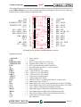
GMM AM328
grifo® Mini Modulo AT mega 328
TECHNICAL MANUAL
Via dell' Artigiano, 8/6
® 40016 San Giorgio di Piano
(Bologna) ITALY
ITALIAN TECHNOLOGY
E-mail: [email protected]
http://www.grifo.it
http://www.grifo.com
Tel. +39 051 892.052 (a.r.) FAX: +39 051 893.661
grifo
GMM AM328
Rel. 5.10
Edition 25 June 2011
®
®
, GPC , grifo , are trade marks of grifo®
GMM AM328
grifo® Mini Modulo AT mega 328
TECHNICAL MANUAL
Standard container with 28 pins male socket, DIL, 100 mils pitch, 600 mils width; very
small dimension: 20.7 x 38.7 x 12.8 mm; single power supply required from +3.0 Vdc
to +5.0 Vdc (the current consumption may vary according to module connections);
availability of Idle Mode and Power Down Mode; Atmel ATmega 328 microcontroller
(AVR RISC) with 7.3728 Mhz crystal; 32KBytes FLASH for code, up to 1K Bytes
FLASH for optional Boot Loader, 1KBytes EEPROM, 2K Bytes SRAM for data;
8 A/D converter channels with 10 bits resolution; 18 interrupt sources; 3 Timers
Counters up to 16 bits, compare, capture, PWM, etc.; programmable Watch Dog
from 16 ms up to 2 s; 23 digital I/O lines available on connector; hardware serial line
with Baud Rate up to 115200 Baud, RS 232 buffered or at TTL level; I2C BUS serial
interface; SPI interface; Reset circuitery; 4 ways configuration dip switch; software
I/O managed status LED; internal FLASH and EEPROM can be managed through
In System Programming, or when the module is already mounted, by using ISP
programming; freeware software for PC, that supports the ISP programmation to
dowload the generated code, inside on board FLASH; wide range of development
tools as: C compiler (ImageCraft ICC AVR,DDS Micro C), BASIC compiler
(BASCOM AVR), etc.; long list of demo programs and use examples supplied under
source form, duly remarked, for the available development tools.
Via dell' Artigiano, 8/6
® 40016 San Giorgio di Piano
(Bologna) ITALY
ITALIAN TECHNOLOGY
E-mail: [email protected]
http://www.grifo.it
http://www.grifo.com
Tel. +39 051 892.052 (a.r.) FAX: +39 051 893.661
grifo
GMM AM328
Rel. 5.10
Edition 25 June 2011
®
®
, GPC , grifo , are trade marks of grifo®
DOCUMENTATION COPYRIGHT BY grifo® , ALL RIGHTS RESERVED
No part of this document may be reproduced, transmitted, transcribed, stored in a
retrieval system, or translated into any language or computer language, in any form or
by any means, either electronic, mechanical, magnetic, optical, chemical, manual, or
otherwise, without the prior written consent of grifo®.
IMPORTANT
Although all the information contained herein have been carefully verified, grifo®
assumes no responsability for errors that might appear in this document, or for damage
to things or persons resulting from technical errors, omission and improper use of this
manual and of the related software and hardware.
grifo® reserves the right to change the contents and form of this document, as well as
the features and specification of its products at any time, without prior notice, to obtain
always the best product.
For specific informations on the components mounted on the card, please refer to the
Data Book of the builder or second sources.
SYMBOLS DESCRIPTION
In the manual could appear the following symbols:
Attention: Generic danger
Attention: High voltage
Attention: ESD sensitive device
Trade Marks
, GPC®, grifo® : are trade marks of grifo®.
Other Product and Company names listed, are trade marks of their respective companies.
grifo®
ITALIAN TECHNOLOGY
GENERAL INDEX
INTRODUCTION ........................................................................................................................ 1
CARD VERSION ......................................................................................................................... 3
GENERAL INFORMATION ...................................................................................................... 4
DIGITAL I/O LINES ............................................................................................................... 6
A/D CONVERTER .................................................................................................................. 6
DIP SWITCH ........................................................................................................................... 6
WATCH DOG .......................................................................................................................... 6
SPI INTERFACE ..................................................................................................................... 6
I2C BUS INTERFACE............................................................................................................. 8
SERIAL COMMUNICATION ............................................................................................... 8
TIMER COUNTER AND PWM ............................................................................................ 8
MEMORY DEVICES .............................................................................................................. 9
CLOCK .................................................................................................................................... 9
TECHNICAL FEATURES ........................................................................................................ 10
GENERAL FEATURES ........................................................................................................ 10
PHYSICAL FEATURES ....................................................................................................... 10
ELECTRIC FEATURES ...................................................................................................... 11
INSTALLATION ........................................................................................................................ 12
VISUAL SIGNALATIONS ................................................................................................... 12
CONNECTIONS ................................................................................................................... 12
CN1 - EXTERNAL POWER SUPPLY CONNECTOR ................................................ 12
MINI MODULE CONFIGURATION ................................................................................. 14
SERIAL COMMUNICATION SELECTION ..................................................................... 16
CONNECTOR SIGNALS INTERFACEMENT ................................................................ 18
POWER SUPPLY .................................................................................................................. 18
INTERRUPTS ....................................................................................................................... 19
SUPPORT CARDS ..................................................................................................................... 20
USE WITH GMB HR84 MODULE ..................................................................................... 20
USE WITH GMM TST 2 MODULE ................................................................................... 22
HOW TO START ....................................................................................................................... 24
RICOMPILATION WITH BASCOM AVR ........................................................................ 28
RICOMPILATION WITH ICC AVR .................................................................................. 30
SOFTWARE DESCRIPTION ................................................................................................... 32
PERIPHERAL DEVICES SOFTWARE DESCRIPTION ..................................................... 34
ACTIVITY LEDS .................................................................................................................. 34
CPU INTERNAL PERIPHERALS ...................................................................................... 34
BIBLIOGRAPHY ....................................................................................................................... 36
GMM AM328 Rel. 5.10
Page I
grifo®
ITALIAN TECHNOLOGY
APPENDIX A: DATA SHEET ................................................................................................. A-1
ATmega8L .............................................................................................................................. A-1
APPENDIX B: ISP PROGRAMMING WITH GMM TST 2 ............................................... B-1
COMMON OPERATIONS FOR ALL PROGRAMMERS ............................................... B-1
PROGRAMMING USING grifo® MP AVR-51+; grifo® UEP 49 ..................................... B-3
PROGRAMMING USING EQUINOX EPSILON5 .......................................................... B-5
PROGRAMMING USING ATMEL AVR ISP .................................................................... B-7
PROGRAMMING USING PONY PROG .......................................................................... B-9
APPENDIX C: GMM TST 2 ELECTRIC DIAGRAM ........................................................ C-1
APPENDIX D: ALPHABETICAL INDEX ............................................................................ D-1
Page II
GMM AM328 Rel. 5.10
grifo®
ITALIAN TECHNOLOGY
FIGURES INDEX
FIGURE 1: LOCATION OF REVISION NUMBER ...................................................................................... 3
FIGURE 2: BLOCK DIAGRAM ............................................................................................................. 7
FIGURE 3: PHOTO OF GMM AM328............................................................................................... 9
FIGURE 4: LED TABLE ................................................................................................................... 12
FIGURE 5: CN1 - SOCKET WITH MINI MODULE SIGNALS ................................................................ 13
FIGURE 6: DSW1 4 WAYS DIP SWITCH TABLE ................................................................................ 14
FIGURE 7: COMPONENTS MAP (COMPONENTS SIDE) ......................................................................... 15
FIGURE 8: LED, DIP SWITCH, ETC. LOCATION ............................................................................... 15
FIGURE 9: EXAMPLE OF RS 232 SERIAL CONNECTION ..................................................................... 17
FIGURE 10: EXAMPLE OF TTL SERIAL CONNECTION ....................................................................... 17
FIGURE 11: IMAGE OF GMB HR 84 AND GMM AM328 WITH AND WITHOUT CONTAINER ............. 21
FIGURE 12: PHOTO OF GMM TST 2 + GMM AM328 CONNECTED TO AVR ISP ........................ 23
FIGURE 13: RS 232 SERIAL CONNECTION BETWEEN GMM AM328 AND PC .................................. 24
FIGURE 14: EXAMPLES TABLE ......................................................................................................... 25
FIGURE 15: BOOT LOADER UTILITY ................................................................................................ 27
FIGURE 16: LOADING A SOURCE FILE WITH BASCOM AVR .......................................................... 28
FIGURE 17: CONFIGURATION OF COMPILER BASCOM AVR ......................................................... 29
FIGURE 18: COMPILATION WITH BASCOM AVR ......................................................................... 29
FIGURE 19: LOADING PROJECT FILE WITH ICC AVR ..................................................................... 30
FIGURE 20: COMPILATION WITH ICC AVR .................................................................................... 30
FIGURE 21: TOP VIEW OF GMM AM328 ...................................................................................... 33
FIGURE 22: POSSIBLE CONNECTIONS DIAGRAM ................................................................................ 35
FIGURE 23: POSSIBLE CONNECTIONS DIAGRAM OF GMM TST 2 AND GMM AM328 .................... 37
FIGURE B-1: DIAGRAM OF INTERFACE BETWEEN GMM TST 2 AND MP AVR-51+ ...................... B-2
FIGURE B-2: DIAGRAM OF INTERFACE BETWEEN GMM TST 2 AND UEP 49 ............................... B-2
FIGURE B-3: DIRECT CONNECTION BETWEEN GMM AM328 AND SEP 40 ................................... B-3
FIGURE B-4: DIRECT CONNECTION BETWEEN GMM AM328 AND UEP 49 .................................. B-3
FIGURE B-5: COMPONENT SELECTION USING PG4UW ................................................................. B-4
FIGURE B-6: DIRECT CONNECTION BETWEEN GMM AM328 AND EPSILON5 OR AVR ISP ...... B-5
FIGURE B-7: DIRECT CONNECTION BETWEEN GMM AM328 AND MP AVR-51+ ........................ B-5
FIGURE B-8: COMPONENT CONFIGURATION USING PG4UW ......................................................... B-6
FIGURE B-9: PROGRAMMER CONFIGURATION USING PG4UW ....................................................... B-6
FIGURE B-10: PROJECT CONFIGURATION USING EQTOOLS ........................................................... B-8
FIGURE B-11: CPU SELECTION USING AVR STUDIO ................................................................... B-10
FIGURE B-12: CPU CONFIGURATION USING AVR STUDIO ........................................................... B-10
FIGURE B-13: AVR ISP CONFIGURATION USING AVR STUDIO .................................................... B-10
FIGURE B-14: LOGO OF PONY PROG .......................................................................................... B-11
FIGURE B-15: CPU SELECTION WITH PONY PROG ..................................................................... B-12
FIGURE B-16: CPU CONFIGURATION WITH PONY PROG ............................................................. B-12
FIGURE B-17: PROGRAMMING USING PONY PROG ....................................................................... B-12
FIGURE C-1: GMM TST 2 ELECTRIC DIAGRAM (1 OF 3) ............................................................. C-1
FIGURE C-2: GMM TST 2 ELECTRIC DIAGRAM (2 OF 3) ............................................................. C-2
FIGURE C-3: GMM TST 2 ELECTRIC DIAGRAM (3 OF 3) ............................................................. C-3
GMM AM328 Rel. 5.10
Page III
grifo®
Page IV
ITALIAN TECHNOLOGY
GMM AM328 Rel. 5.10
ITALIAN TECHNOLOGY
grifo®
INTRODUCTION
The use of these devices has turned - IN EXCLUSIVE WAY - to specialized personnel.
This device is not a safe component as defined in directive 98-37/CE.
Pins of Mini Module are not provided with any kind of ESD protection. They are connected directly
to their respective pins of microcontroller. Mini Module is affected by electrostatic discharges.
Personnel who handles Mini Modules is invited to take all necessary precautions to avoid possible
damages caused by electrostatic discharges.
The purpose of this handbook is to give the necessary information to the cognizant and sure use of
the products. They are the result of a continual and systematic elaboration of data and technical tests
saved and validated from the manufacturer, related to the inside modes of certainty and quality of
the information.
The reported data are destined- IN EXCLUSIVE WAY- to specialized users, that can interact with
the devices in safety conditions for the persons, for the machine and for the enviroment, impersonating
an elementary diagnostic of breakdowns and of malfunction conditions by performing simple
functional verify operations , in the height respect of the actual safety and health norms.
The informations for the installation, the assemblage, the dismantlement, the handling, the adjustment,
the reparation and the contingent accessories, devices etc. installation are destined - and then
executable - always and in exclusive way from specialized warned and educated personnel, or
directly from the TECHNICAL AUTHORIZED ASSISTANCE, in the height respect of the
manufacturer recommendations and the actual safety and health norms.
The devices can't be used outside a box. The user must always insert the cards in a container that
rispect the actual safety normative. The protection of this container is not threshold to the only
atmospheric agents, but specially to mechanic, electric, magnetic, etc. ones.
To be on good terms with the products, is necessary guarantee legibility and conservation of the
manual, also for future references. In case of deterioration or more easily for technical updates,
consult the AUTHORIZED TECHNICAL ASSISTANCE directly.
GMM AM328
Rel. 5.10
Page 1
grifo®
ITALIAN TECHNOLOGY
To prevent problems during card utilization, it is a good practice to read carefully all the informations
of this manual. After this reading, the user can use the general index and the alphabetical index,
respectly at the begining and at the end of the manual, to find information in a faster and more easy
way.
Page 2
GMM AM328
Rel. 5.10
grifo®
ITALIAN TECHNOLOGY
CARD VERSION
This handbook make reference to card GMM AM328 with printed circuit version 110903.
The validity of the information contained in this manual is subordinated to the printed circuit revision
number and so the user must always check the correspondance.
The printed circuit revision number is always printed in several positions of the circuit and following
figure shows the easiest to access.
PRINTED CIRCUIT REVISION NUMBER
FIGURE 1: LOCATION OF REVISION NUMBER
GMM AM328
Rel. 5.10
Page 3
grifo®
ITALIAN TECHNOLOGY
GENERAL INFORMATION
GMM AM328 (grifo® Mini Module ATMEL ATmega328) is a module based on microcontroller
Atmel ATmega328, a powerful and complete system-on-a-chip provided with CPU, internal
memory both for data and for code, A/D converter, watch dog, interrupts, TTL digital I/O lines,
a hardware serial line, dedicated timer/counter with capture/compare and PWM capability , SPI
interface, I2C BUS (two wires interface synchronous line), etc.
In modules's very small area some comoponents that exploit microcontrollers's performance are
already mounted.
In addition to this, component that completemicro's features are installed, like the reset circuitery.
Possible applications of GMM AM328 Mini Modules are several.
We remark the employ as smart intelligent nodes with local functionalities as PID algorithms for
controlling temperatures, motors, valves, etc. or as decentralized systems as robots, automation of
production line machines, big factory automations.
Finally, teleacquisition and telecontrol on medium and low distances, home automation (lights
turning ON/OFF, heating and cooling systems control, supervision of electric devices, security and
acces control systems).
Last but not least, didactics: GMM AM328 offers a very low cost to learn how a real AVR RISC
microcontroller works and to develop typical applications for this family.
For this purpose it is likewise interesting the GMM TST 2 support card.
GMM TST 2 allows to connect immediatly a RS 232 interface to communicate to a PC and a
reference voltage source for A/D converter.
In addition, it is delivered with a 4x4 matrix keyboard and a 20x2 LCD backlit display, allowing
to implement easily terminal emulators and to design user interfaces.
GMM TST 2 is also capable to program internal memories using a very comfortable AVR ISP
programmer, to speed up the internal memories programming and so making the production faster.
Multilingual free software made by LancOS, and italian brand, can also be used.
It requires only a RS 232 port (for example, on the PC) and a standard serial connection cable to
program internal memories of Mini Module installed on GMM TST 2.
GMM AM328 is delivered with a Boot Loader preinstalled. This program allows to reprogram Flash
and EEPROM through a simple RS 232 serial port (for example, PC COM port).
In any case, there is a short time to market: the user can see a prototype or even a ready product in
one week.
Overall features are:
- Standard container with 28 pins male socket, DIL, 100 mils pitch, 600 mils width
- Very small dimension: 20.7 x 38.7 x 12.8 mm; single power supply required from +3.0 Vdc to
+5.0 Vdc (the current consumption may vary according to module connections)
- Availability of Idle Mode and Power Down Mode
- Atmel ATmega328 microcontroller (AVR RISC) with 7.3728 Mhz crystal
- 32KBytes FLASH for code, up to 1K Bytes FLASH for optional Boot Loader, 1K bytes
EEPROM, 2K Bytes SRAM for data
- 8 A/D converter channels with 10 bits resolution
- 18 interrupt sources; 3 Timers Counters up to 16 bits, compare, capture, PWM, etc.
- Programmable Watch Dog from 16 ms up to 2 s
- 23 digital I/O lines available on connector
Page 4
GMM AM328
Rel. 5.10
ITALIAN TECHNOLOGY
grifo®
- Hardware serial line with Baud Rate up to 115200 Baud, RS 232 buffered or at TTL level
- I2C BUS serial interface
- SPI interface
- Reset circuitery
- 4 ways configuration dip switch
- Software I/O managed status LED
- Internal FLASH and EEPROM can be managed through In System Programming, or when
the module is already mounted, by using ISP programming
- Freeware software for PC, that supports the ISP programmation to dowload the generated code,
inside on board FLASH
- Wide range of development tools as: C compiler (ImageCraft ICC AVR,DDS Micro C), BASIC
compiler (BASCOM AVR), etc.
- Long list of demo programs and use examples supplied under source form, duly remarked, for
the available development tools.
Here follows a description of the board's functional blocks, with an indication of the operations
performed by each one.
To easily locate such section on verify their connections please refer to figure 2.
GMM AM328
Rel. 5.10
Page 5
grifo®
ITALIAN TECHNOLOGY
DIGITAL I/O LINES
The Mini Module GMM AM328 is provided with 23 TTL digital I/O lines, of the microprocessor
Atmel ATmega328, that are all the signals of Ports PB, PD and from PC0 to PC6.
These lines are connected directly to 28 pins connectors with standard grifo® Mini Module pin out,
allowing to be connected direclty to several interface cards.
By software it is possible to define and acquire the function and the status of these lines, and also to
match them to peripheral devices (like Timer Counter, Interrupt, I2C BUS, SPI, etc.), simply
programming some CPU internal registers.
For further information please refer to paragraph CONNECTIONS and PERIPHERAL DEVICES
SOFTWARE DESCRIPTION.
A/D CONVERTER
Mini Module GMM AM328 is provided with an eight channels A/D converter, multiplexed on some
signals of port PC, plus signals ADC6 and ADC7 not multiplexed.
Reference voltage can be fetched externally through a pin or internal reference generator can be used.
Range of signals is from 0 to +Vdc POW, analog signals generators must have a low impedance.
Conversion end can be used to trigger an interrupt, if enabled.
Peripheral management is performed by manipulating specific microcontroller internal registers.
For further information please refer to Appendix A or to the comments in our examples.
DIP SWITCH
GMM AM328 Mini Module is provided with an on board dip switch whose purpose is to switch
between RS 232 or TTL serial signals.
In fact they decide whether RS 232 signals generated by MAX 3222E or CPU TTL USART signals
reach the pins of the socket.
WATCH DOG
Microcontroller ATmega328 is provided with an internal hardware watch dog capable to reset the
CPU if the user program cannot retrigger it in less than the selected intervent time.
Intervent time range is rather wide, it is from about 16 ms to 2 s.
SPI INTERFACE
Microcontroller ATMEL ATmega328 can be programmed In-Circuit through its SPI interface, but
the same interface is also available to the user.
In fact, other devices provided with the same communication interface can be interconnected to the
application.
Page 6
GMM AM328
Rel. 5.10
grifo®
+Vdc POW = +5 Vdc
2 Lines
1 signal
LED
7 Lines
Reset circuit
/RESET
2 Lines
3 Lines
28 pins socket CN1
2 Lines
Internal MUX
8 Lines
20 signals
2 Lines
USART
23 Lines
2 signals
(TTL serial line)
RS 232 DRIVER
protection ±15 kV
CPU
AT mega 328
CLK
PWM
ANALOG
1 KB
2 KB 32 KB WATCH PORT USART SPI INT I2C A/D
BROWN
TIMER
COMPARATOR
CONV.
EEPROM SRAM FLASH DOG
I/O
OUT
COUNTER
ITALIAN TECHNOLOGY
I2C BUS
2 signals
FIGURE 2: BLOCK DIAGRAM
GMM AM328
Rel. 5.10
Page 7
grifo®
ITALIAN TECHNOLOGY
I2C BUS INTERFACE
Standard pin out of 28 pins grifo® Mini Module connector reserves two pins, 6 and 7, to I2C BUS
interface. These signals are provided with a 4.7 kΩ pull-up on the Mini Module board.
GMM AM328 features a hardware I2C BUS interface and is managed through microcontroller
inernal registers. It can work both as master or slave, in transmission or reception.
This interface allows to connect components featuring the same communication standard to expand
locally the potentialities of Mini Module.
For this Mini Module, a rich serie of demo programs that explain how to use A/D and D/A converters,
memories, temperature sensors, etc. by a complete and well commented code is available.
Remarkable is the possibility to connect the grifo® QTP operator panels serie through I2C BUS.
QTP are capable to manage alphanumeric and graphic display and several models of keyboards,
according to the model selected.
Mini Modules support cards manufactured by grifo® (like GMB HR84) are provided also with a
connector dedicated to I2C BUS, to easy the field connections.
SERIAL COMMUNICATION
On GMM AM328 there is always availability of one hardware serial line that is completely software
configurable for physical protocol (baud rate, stop bits number, lenght of character, etc) by simply
programming some microprocessor registers as described in the manufacturer documentation or in
the appendix of this manual.
The serial lines are connected to CN1 connector at TTL or RS 232 level, thanks to some on board
dip switches configuration, so when the card must be connected in a network or at long distance or
with other systems that use different electric protocol, the user must provide external drivers (RS 232,
RS 422, RS 485, Current loop, etc.).
Please remember that on CN1 connector more than standard receive and transmit signals are
available also other I/O signals that can be driven by software; these signals can be used to define
the RS 485 line direction, to enable the RS 422 transmit drive or to generate an RS 232 handshake.
For example it can be used the MSI 01 module that converts a TTL serial line in any other electric
standards in a pratical and inexpensive way.
Please read SERIAL COMMUNICATION SELECTION paragraph of this manual or contact
directly grifo® technician for further explanation or any other necessary information.
TIMER COUNTER AND PWM
Microcontroller is provided with three Timer/Counter (two featuring eight bits, one featuring sixteen
bits) capable to count clock pulses (through a programmable prescaler), level transictions on specific
pins and to generate interrupts.
They can also be used in PWM mode, to generatesignals of variable duty cycle and frequency set by
software with eight or sixteen bits of resolution.
Typical applications of these signals are motor velocity control, in fact several motor control cards
are provided with compatible inputs.
Another application is analog signals generation by simply adding an integrator.
Page 8
GMM AM328
Rel. 5.10
ITALIAN TECHNOLOGY
grifo®
MEMORY DEVICES
The card is provided of 9.5K of memory divided with a maximum of 32KBytes FLASH EPROM,
2KBytes of internal SRAM and 1K Bytes EEPROM.
The memory configuration must be chosen considering the application to realize or the specific
requirements of the user.
Thanks to on board EEPROM there is the possibility to keep data also when power supply is failed.
In this way the card is always able to maintain parameters, logged data, system status and
configuration, etc. in each working conditions.
Whenever the amount of memory for data is not sufficient (i.e. for data loghin systems), it is always
possible to connect external memory devices (with SRAM, EEPROM, FLASH technologies)
through the comfortable and efficient SPI and I2C BUS interface of the card.
The addressing of memory devices is controlled by microcontroller as described in the component
data sheet or in APPENDIX A of this manual.
CLOCK
On GMM AM328 module there is a circuitery that generates a 7.3728 MHz frequency for the
microcontroller.
About speed and performances please remind that GMM AM328 has a RISC microcontroller on
board, capable to execute in average one instruction per clock cycle.
So, considering the frequency of quartz installed, execution speed may be almost 7 MIPS.
FIGURE 3: PHOTO OF GMM AM328
GMM AM328
Rel. 5.10
Page 9
grifo®
ITALIAN TECHNOLOGY
TECHNICAL FEATURES
GENERAL FEATURES
Devices:
23 digital TTL I/O signals
8 A/D converter analog inputs
1 Watch Dog section
3 Programmable Timer/Counters
18 interrupt sources
1 reset circuitery
1 RS 232 serial line through MAX 3222
1 four ways dip switch
1 status LED (red)
Memories:
32 Kbyte FLASH
up to 1K byte FLASH
1K Bytes EEPROM
2K Bytes SRAM
CPU:
Atmel ATmega328
Clock frequency:
7.3728 MHz
user program
boot loader
user data
user data
Counters maximum frequency: I/O clock frequency
Power on time:
79 ms
A/D resolution:
8 lines at 10 bit
A/D conversion time:
20 µs
PHYSICAL FEATURES
Size:
20.7 x 38.7 x 12.8 mm
Weight:
6.8 g
Connectors:
28 pins male socket DIL
Temperature range:
0÷50 °C
Relative humidity:
20%÷90%
Page 10
(without condense)
GMM AM328
Rel. 5.10
ITALIAN TECHNOLOGY
grifo®
ELECTRIC FEATURES
Power supply voltage:
called +Vdc POW, from +3.0 Vdc to +5.0 Vdc
Current consumption at +5.0 V:
3 ma
15 ma
18 ma
(power down mode)
(normal working mode)
(highest)
Current consumption at +3.0 V:
2 ma
9 ma
10 ma
(power down mode)
(normal working mode)
(highest)
Impedance analog signals generators: <10 kΩ
RS 232 protection:
±15 kVdc
I2C BUS pull-up resistor:
4.7 kΩ
Brown out threshold:
2.7 or 4.0 Vdc with hysteresis
GMM AM328
Rel. 5.10
Page 11
grifo®
ITALIAN TECHNOLOGY
INSTALLATION
In this chapter there are the information for a right installation and correct use of the GMM AM328
card. In detail there are the locations and functions of each connector, of the user settable dip
switches, LEDs, and so on.
VISUAL SIGNALATIONS
GMM AM328 features the LED described in the following table:
LED
PURPOSE
DL1
Driven by signal PB.5 , SCK of Mini Module, it can be used as activity LED
and can be managed by software.
FIGURE 4: LED TABLE
The main function of LED is to inform the user about card status, with a simple visual indication and
in addition to this, LED makes easier the debug and test operations of the complete system. To
recognize the LED location on the card, please refer to figure 8. while for further information please
refer to paragraph ACTIVITY LEDS.
CONNECTIONS
The GMM AM328 module has 1 connector that can be linkeded to other devices or directly to the
field, according to system requirements.
In this paragraph there are connector pin out, a short signals description (including the signals
direction) and connectors location (see figure 8) that simplify and speed the installation phase. Some
additional figures shows the pins functionalities and some of the most frequently used connections.
CN1 - EXTERNAL POWER SUPPLY CONNECTOR
CN1 is a 28 pins, male, dual in line, socket connector with 100 mils pitch and 600 mils width.
On CN1 are available all the interfacement signals of the Mini Module as the power supply, the
I/O lines, the synchronous and asynchronous communication lines, the on board peripheral devices
signals, the operating mode selection lines, etc.
Some pins of this connector have multiple purposes, in fact they can be multiplexed by programming
some software registers with several CPU internal devices and the following figure lists all these
possible functionalities. So the signals available on CN1 have different types as described in the
following CONNECTOR SIGNALS INTERFACEMENT paragraph and they follow grifo® Mini
Module standard pin out.
Page 12
GMM AM328
Rel. 5.10
grifo®
ITALIAN TECHNOLOGY
To avoid problems in pin counting and numbers the figure 5 shows the signals directly on the top view
of the GMM AM328; moreover the serigraph reports the pins number on the four corner of the card
both on bottom (solder) and top (component) side.
Vref
/RES , PC6
RxD RS232 TTL , PD0
TxD RS232 TTL , PD1
N. C.
PC5 , ADC5 , SCL
PC4 , ADC4 , SDA
PB3 , MOSI , OC2
PB4 , MISO
ADC6
N. C.
PB5 , SCK
PC3 , ADC3
GND
1
2
3
4
5
6
7
8
9
10
11
12
13
14
28
27
26
25
24
23
22
21
20
19
18
17
16
15
+Vdc POW
ADC7
PC0 , ADC0
PC1 , ADC1
PB1 , OC1A
PB0 , ICP
PB2 , OC1B , /SS
PD6 , AIN0
PD7 , AIN1
PD2 , INT0
PD3 , INT1
PD4 , T0 , XCK
PD5 , T1
PC2 , ADC2
FIGURE 5: CN1 - SOCKET WITH MINI MODULE SIGNALS
Signals description:
+Vdc POW
GND
RxD RS232 TTL
TxD RS232 TTL
INTn
Tn
/RES
PB0÷7
PC0÷6
PD0÷7
ADC0÷7
AIN0÷1
OCxy
ICP
SDA
SCL
SCK
MOSI
MISO
/SS
Vref
N. C.
GMM AM328
= I - Power supply
=
- Ground
= I - Receive Data of RS 232 or TTL line
= O - Transmit Data of RS 232 or TTL line
= I - CPU external interrupts (INT0 and INT1)
= I - External inputs for timer 0, 1 and 2 counters
= I - Reset signal of CPU
= I/O - CPU Port B I/O TTL signals
= I/O - CPU Port C I/O TTL signals
= I/O - CPU Port D I/O TTL signals
= I - A/D converter analog inputs
= I - Analog multiplexer inputs
= O - Match of Timer 1 (A and B) and Timer 2 compare units
= I - Input capture pin of Timer 1
= I/O - Data signal of two wires serial synchronous interface (I2C BUS)
= I - Clock signal of two wires serial synchronous interface (I2C BUS)
= I - Clock signal of SPI serial synchronous interface
= I - Data input signal of SPI serial synchronous interface
= I - Data output signal of SPI serial synchronous interface
= I - Slave Select signal of SPI serial synchronous interface
= I - A/D converter reference voltage
=
- No connection
Rel. 5.10
Page 13
grifo®
ITALIAN TECHNOLOGY
MINI MODULE CONFIGURATION
On GMM AM328 module there is a 4 ways dip switch that defines some configurations of the card.
In the following figure is reported their list, their position and their functions in all the available
connection modes.
The * (asterisk) denotes the default connection, or on the other hand the connection set up at the end
of testing phase, that is the configuration the user receives.
To recognize the configuration elements location, please refer to figure 8.
For further information about serial communication lines, please refer to paragraph SERIAL
COMMUNICATION SELECTION.
SWITCH
POSITION
PURPOSE
DEF.
ON
Connects signal RxD RS232 TTL , PD0 of socket CN1
to on board RS 232 driver. Used in conjunction with
switch 3.
*
OFF
Does not connect signal RxD RS232 TTL , PD0 of socket
CN1 to on board RS 232 driver, allowing a direct
connection to microcontroller. Used in conjunction with
switch 3.
ON
Connects signal TxD RS232 TTL , PD1 of socket CN1
to on board RS 232 driver. Used in conjunction with
switch 4.
OFF
Does not connect signal TxD RS232 TTL , PD1 of socket
CN1 to on board RS 232 driver, allowing a direct
connection to microcontroller. Used in conjunction with
switch 4.
ON
Connects signal RxD RS232 TTL , PD0 of socket CN1
directly to the microcontroller, excluding the on board
RS 232 driver. Used in conjunction with switch 1.
1
2
3
OFF
ON
4
OFF
Does not connect signal RxD RS232 TTL , PD0 of socket
CN1 directly to microcontroller, allowing to use the on
board RS 232 driver. Used in conjunction with switch 1.
Connects signal TxD RS232 TTL , PD1 of socket CN1
directly to the microcontroller, excluding the on board
RS 232 driver. Used in conjunction with switch 2.
Does not connect signal TxD RS232 TTL , PD1 of socket
CN1 directly to microcontroller, allowing to use the on
board RS 232 driver. Used in conjunction with switch 2.
*
*
*
FIGURE 6: DSW1 4 WAYS DIP SWITCH TABLE
Page 14
GMM AM328
Rel. 5.10
grifo®
ITALIAN TECHNOLOGY
FIGURE 7: COMPONENTS MAP (COMPONENTS SIDE)
DL1
DSW1
FIGURE 8: LED, DIP SWITCH, ETC. LOCATION
GMM AM328
Rel. 5.10
Page 15
grifo®
ITALIAN TECHNOLOGY
SERIAL COMMUNICATION SELECTION
Serial communication line of GMM AM328 can be buffered as RS 232 or TTL.
By software, it is possible to define physical communicatin protocol for the line setting some
microcontroller internal registers.
The serial interface has its own group of registers for configuration, and can work in total
independence respect to the other peripherals.
Electric protocol is selected by hardware and requires the dip switches to be configured correctly,
as described in previous tables; the user can set any configuration in autonomy following the below
reported information:
- SERIAL LINE CONFIGURED AS RS 232 (default configuration)
DSW1.1 =
ON
DSW1.2 =
ON
DSW1.3 =
OFF
DSW1.4 =
OFF
- SERIAL LINE CONFIGURED AS TTL
DSW1.1
DSW1.2
DSW1.3
DSW1.4
=
=
=
=
OFF
OFF
ON
ON
Figures 9 and 10 show how to connect a generic external system to both serial lines of GMM AM328.
Page 16
GMM AM328
Rel. 5.10
grifo®
CN1 GMM AM328
3
4
TX
RxD RS232 TTL (set as RS232)
RX
TxD RS232 TTL (set as RS232)
14 GND
GND
External System
ITALIAN TECHNOLOGY
FIGURE 9: EXAMPLE OF RS 232 SERIAL CONNECTION
4
RxD RS232 TTL (set as TTL)
TxD RS232 TTL (set as TTL)
14 GND
TX
RX
GND
External System
CN1 GMM AM328
3
FIGURE 10: EXAMPLE OF TTL SERIAL CONNECTION
GMM AM328
Rel. 5.10
Page 17
grifo®
ITALIAN TECHNOLOGY
CONNECTOR SIGNALS INTERFACEMENT
To prevent possible connecting problems between GMM AM328 and the external systems, the user
has to read carefully the previous paragraph information and he must follow these instrunctions:
- For RS 232 signals the user must follow the standard specifications of these protocols, defined by
specific normatives.
- All TTL signals must follow the rules of this electric standard. The connected digital signals must
be always referred to card ground (GND) and then the 0V level corresponds to logic state 0, while
the +Vdc POW level corrisponds to logic state 1. The connection of these lines to devices of the
controlled system (encoders, switches, proximity, electric valves, power relays, etc.) must be
performed through proper power interfaces; it is preferible to adopt opto coupled interfaces that
ensure an electric insulation between Mini Module electronic and external noisy, typically
generated by power electronic.
- The inputs for analog comparator must be connected to signals generators featuring a low
impedance in the range from 0 to +Vdc POW , to assure greater stability and precision.
- The inputs for A/D converter must be connected to signals generators featuring a low impedance
in the range from 0 to +Vdc POW, to assure greater stability and precision.
- PWM signals generated by Timer Counter and OCM sections are TTL type so they must be buffered
to interface the power circuitery. Typical interfaces can be current driver (if PWM signal is still
required) or an intergrator circuit if analog voltage is required.
- Also I2C BUS and SPI signals are at TTL level, as defined by the same standards; for completeness
it is remarked that in a network with several devices and rather long it is better to study the
connection lay out and to set properly the output stage, the best operational modes and the
programmable bit rate: all these conditions allow communications in any condition. On Mini
Module, signals SDA and SCL are pulled-up to +Vdc POW through 4.7 kΩ resistors.
POWER SUPPLY
Mini Module can be supplied by a continuous tension in the range from +3.0 V to +5.0 Vdc called
+Vdc POW in this manual.
GMM AM328 design adopted all the circuital and componentistic options that reduce sensibility to
noise and reduce consumption, including the possibility to switch the microcontroller to low
consumption modes.
In optimal situation, the minimun consumption (in power down mode) is 2 mA, so it can, for example,
increase battery life in case of portable applications.
For further information please refer to paragraph ELECTRIC FEATURES.
Page 18
GMM AM328
Rel. 5.10
ITALIAN TECHNOLOGY
grifo®
INTERRUPTS
A remarkable feature of GMM AM328 card is the powerful interrupt management.
Here follows a short description of which devices can geneate interrupts and their modalities; for
further information about interrputs management please refer to the microprocessor data sheet or
APPENDIX A of this manual.
- Pin 19 of CN1 ->
- Pin 18 of CN1 ->
- CPU peripherals ->
Generates an interrupt INT0 of microprocessor.
Generates an interrupt INT1 of microprocessor.
Generate an internal interrupt. In detail the possible microcontroller
interrupt sources are: Timer Counter, OCM, USART, analog
comparator, A/D converter, I2C BUS, SPI, EEPROM, etc.
An interrupt management section, integrated in microcontroller, allows to enable, disable and mask
so the user has the possibility to respond promptly and efficently to any external event.
The microcontroller has an interrupt section that let the user manage the 18 interrupt sources. So
theapplication program has always the possibility to react promptly to every event.
GMM AM328
Rel. 5.10
Page 19
grifo®
ITALIAN TECHNOLOGY
SUPPORT CARDS
GMM AM328 Mini Module can be used as a macro components for some support cards either
developed by the user or directly chosen from the grifo® boards. In the following paragraphs are
reported the suggested configuration of the most interesting support cards.
USE WITH GMB HR84 MODULE
Amongst grifo® cards, GMB HR84 module is the one designed specifically to provide to 28 pins
Mini Modules many interesting features as: 8 optocoupled inputs, 4 relay outputs, mechanical
mounting on omega rails and a comfortable wiring through screw terminal connectors. The complete
description of the product is available in the relative data sheet and technical manual while in this
paragraph are listed the advantages obtained by using this pair of cards:
GMB HR84 allows easily to:
- to supply the Mini Module through on board power supply;
- to have eight TTL I/O signals of microprocessor ports optocoupled NPN and PNP at the same time
and visualized through green LEDs; I/O signals are multiplexed with timer inputs, so developed
functions like counters are immediatly available;
- to have four TTL I/O signals of microprocessor ports on bufferd relays driving and visualized
through red LEDs;
- to connect on I2C BUS and +5 Vdc power supply on a dedicated connector;
- to connect immediatly communication serial line through a comfortable 9 ways DB9 connector;
- to buffer easily TTL USART signals from microprocessor in RS 422, RS 485 or current loop;
- to connect PWM signal through a comfortable standard AMP connector;
The serial connection cable with development PC is the CCR 9+9 R (or in other words a reversed
extension cable provided of D9 Female and D9 Male connectors).
Page 20
GMM AM328
Rel. 5.10
ITALIAN TECHNOLOGY
grifo®
FIGURE 11: IMAGE OF GMB HR 84 AND GMM AM328 WITH AND WITHOUT CONTAINER
GMM AM328
Rel. 5.10
Page 21
grifo®
ITALIAN TECHNOLOGY
USE WITH GMM TST2 MODULE
Amongst grifo® cards, GMM TST2 is the one designed specifically to provide a first entry point to
28 and 40 pins Mini Modules, with suitable evaluation purposes.
The complete description of the product is available in the relative data sheet and technical manual,
is electric diagram is in appendix B of this manual.
In this paragraph are listed the advantages obtained by using this pair of cards.
The GMM TST2 allows easily to:
- supply the Mini Module through on board AC, DC power supply;
- connect all the I/O signals of microcontroller ports on comfortable connectors compatible with
I/O ABACO® standard pin out;
- connect immediately USART serial line through a comfortable 9 pins D type connector;
- set and show the status of 2 microcontroller I/O lines through push button and LEDs with different
colours;
- generate audible feed back thanks to active buzzer mounted on board;
- develop in a short time user interface applications by using the on board matrix keyboard with
4x4=16 keys and the backlite LCD display with 2 rows of 20 characters;
- develop easily a support card that satisfy customer requirements starting from the supplied electric
diagrams;
- program FLASH and EEPROM using the Boot Loader and in ISP modality.
The following configuration is suggested to use the couple GMM TST 2 + GMM AM328 in their
base version, that is RUN mode with serial line buffered in RS 232:
GMM AM328 configuration
DSW1.1 =
ON
DSW1.2 =
ON
DSW1.3 =
OFF
DSW1.4 =
OFF
GMM TST 2 configuration
J1 =
2-3
J2 =
2-3
J3 =
not connected
J4 =
not connected
J5 =
not connected
J6 =
not connected
J7 =
not connected
The serial connection cable with development PC is the CCR 9+9 E (or in other words an extension
cable provided of D9 Female and D9 Male connectors).
Page 22
GMM AM328
Rel. 5.10
ITALIAN TECHNOLOGY
grifo®
FIGURE 12: PHOTO OF GMM TST 2 + GMM AM328 CONNECTED TO AVR ISP
GMM AM328
Rel. 5.10
Page 23
grifo®
ITALIAN TECHNOLOGY
HOW TO START
One of the most intrersting features is the possibility to program the content of microcontroller on
board FLASH and EEPROM using specific tools manufactured by grifo® and Atmel.
Across this chapter we presume that you have a GMM TST 2 or a GMB HR84 where to install GMM
AM328.
For further information please refer the specific manual of GMB HR84 + GMM AM328.
A) SERIAL CONNECTION BETWEEN GMM AM328 AND PC
A1) To make the serial connection between GMM AM328 and a PC, the structure described
on figure 13 should be built.
The program delivered to the customer in the Mini Module performs the blink of the on
board LED, without using the serial interface. Demo program uses widly such interface,
it also provides a section dedicated to it. So it is a good idea to make the serial connection
as first thing.
CN1 GMM AM328
3
4
RxD RS232 TTL (set as RS232)
TxD RS232 TTL (set as RS232)
14 GND
2
3
TX
3
2
RX
7
5
GND
Connector to P.C.
COM serial line
DB25F DB9F
FIGURE 13: RS 232 SERIAL CONNECTION BETWEEN GMM AM328 AND PC
A2) Keep ready for running a terminal emulator on PC, configure it to use the serial port where
Mini Module is connected with 19200 baud, 8 data bits, 1 stop bit, no parity. If you are
using BASCOM AVR, you may simply open the terminal emulator in its IDE.
Page 24
GMM AM328
Rel. 5.10
ITALIAN TECHNOLOGY
grifo®
A3) Supply GMM TST 2 or GMB HR84. LED of Mini Module should start blinking about
twice per second.
FIGURE 14: EXAMPLES TABLE
GMM AM328
Rel. 5.10
Page 25
grifo®
ITALIAN TECHNOLOGY
B) FLASH REPROGRAMMING
Mini Module programming is performed using th Boot Loader preprogrammed in the Flash of Mini
Module itself.
Such program allows to create a communication between Mini Module and the PC, and to use it to
send a .hex file to code memory and/or EEPROM memory area of microcontroller.
Boot Loader does not allow to program configuration bits and security fuses of microcontroller, this
can be done usigne ISP programming (please refer to appendix B of this manual).
The portion of Flash memory taken by the Boot Loader is 2 KBytes, this means that the last block
of 1 KWord at the end of the memory is reserved to Boot Loader and is not available for user
application any more.
Boot Loader communicates through PC serial port installing a specific utility (that can be
downloaded for free from our website www.grifo.com or can be found in our CD) called
AVRBootloaderGrifo.exe. This utility allows to select the serial port to use end to select the files to
program memories of Mini Module.
For some applications, use of an ISP programmer may be the only chance. Please refer to appendix
B for more information about ISP programming.
Combo box called "Com Port" allows to select the serial port to use for communication with Mini
Module.
Checking the ckeck box "Application Code" the file whose name is written in the text box on the right
will be stored in Flash of Mini Module. To choose the file press the "Browse" button.
Chek box "EEPROM Code" performs the same operation described above, but writes to EEPROM.
There is also the possibility to use AVRBootloaderGrifo from DOS window, commands prompt, a
command line or as an external tool of an IDE.
Option for command line are:
/com1 , /com2 , ... , /com9 Number of serial port used for communication.
Serial ports from COM1 to COM9 are supported
/f <FLASHProgram>
Indicates the complete pathname of the .HEX file to write in
microcontroller FLASH memory
/e <EEPROMProgram>
Indicates the complete pathname of the .HEX file to write in
microcontroller EEPROM memory
For example:
AVRBootloaderGrifo.exe /com2 /f C:\Projects\MotorControl\Main.hex
opens a connection on serial port COM2 to the Boot Loader and sends the file Main.hex located in
folder C:\Projects\MotorControl\.
To integrate AVRBootloaderGrifo.exe in a IDE, for example the one of BASCOM AVR (described
at point C) the user must:
1) Open the window of menu Options | Programmer
2) In the text box Programmer choose "External Programmer"
3) Click the tab Other
4) In text box Program insert the complete pathname of AVRBootloaderGrifo.exe pressing Browse
5) In text box Parameters insert command line parameter for AVRBootloaderGrifo
Please remaind that the string {file} in the above mentioned text box is automatically replaces by
BASCOM AVR with the name of .hex file just generated.
Please refer to BASCOM AVR documentation for further information.
Page 26
GMM AM328
Rel. 5.10
ITALIAN TECHNOLOGY
grifo®
B1) Find on CD grifo® and save to a comfortable position on your hard drive the demo
program"d_am328u1.hex". It can be found starting from main page following the path:
English | Examples tables | Mini Modules and Mini Block examples | GMM AM328
(please refer to figure 14). You may want to remove the read-only attribute.
B2) Connect the Mini Module to PC serial port makin the connection described at point A.
Close the terminal emulator.
B3) Indicate in combo box "Com Port" the serial port connected at the previous point.
B4) Check the check box "Application Code" and press the button "Browse" on the right, then
select the file previously saved at point B1.
B5) Uncheck the check box "EEPROM Code", if checked.
B6) Press the button "Synch to Bootloader..." or the key combination Alt+S on the PC, then
reset the Mini Module or turn off and then on its supply. The file is dowloaded into the
Mini Module. If this does not happen, and the program should indicate a "No repsonse
from target bootloader", try to repeat the operation decreasing the time between pressure
of button on the PC and reset of Mini Module. If the problem persists, check cable and
connection.
B7) When operation is completed the program reports its status. In case of problems, check
cable and connection.
B8) Start the terminal emulator configured like in point A2 and verify that the application
program just downloaded is executed in internal Flash.
FIGURE 15: BOOT LOADER UTILITY
GMM AM328
Rel. 5.10
Page 27
grifo®
ITALIAN TECHNOLOGY
C) GENERATING DEMO EXECUTABLE CODE
C1) Install on the hard disk of the development P.C. the software environment selected to
develop the application program. As described in the chapter SOFTWARE
DESCRIPTION there are many different software tools that satisfy any customers
requirements but here we remind only the most diffused as the BASCOM AVR, ICC
AVR, etc.
C2) On grifo® CD in addition to file with the executable code of the demo program, described
at point B2, there are also the source files of the same. These have an extension that
identifies the used software development tools (for example d_am08u1.bas for BASCOM
AVR or d_am328u1.c for ICC AVR) and they are properly organized inside demo
programs tables available on CD, together with possible definition file (for example:
d_am328u1.prj for ICC AVR). Once these files have been located they must be copied
in a comfortable folder on the hard disk of development PC.
C3) Compile the source file by using the selected software tools: the file d_am08u1.hex must
be obtained equal to those available on grifo® CD and already used at points B. This
operation is very different according to the programming environment selected, so here
follow the details:
C3 Bascom AVR) Ricompilation using BASCOM AVR.
C3 Bascom AVR a) In BASCOM IDE, load the program source with menu File | Open:
FIGURE 16: LOADING A SOURCE FILE WITH BASCOM AVR
Page 28
GMM AM328
Rel. 5.10
grifo®
ITALIAN TECHNOLOGY
C3 Bascom AVR b) From menu Options | Compiler | Chip set the value 64 for HW Stack,
32 for Soft Stack, 64 for Framesize, as suggesterd also in the source
code, and press OK. Such values must be considered minimal and
must be increased if required:
FIGURE 17: CONFIGURATION OF COMPILER BASCOM AVR
C3 Bascom AVR c) Compile the source file by pressing the button with the icon of an
integrated circuit.
FIGURE 18: COMPILATION WITH BASCOM AVR
GMM AM328
Rel. 5.10
Page 29
grifo®
ITALIAN TECHNOLOGY
C3 ICC AVR) Ricompilation with ICC AVR.
C3 ICC AVR a) In standard editor, load the project file d_am328u1.prj using the menu
Project | Open...:
FIGURE 19: LOADING PROJECT FILE WITH ICC AVR
C3 ICC AVR b) Compile the project using the menu Project | Make project:
FIGURE 20: COMPILATION WITH ICC AVR
Page 30
GMM AM328
Rel. 5.10
ITALIAN TECHNOLOGY
grifo®
C4) Program the compiled file into FLASH memory of GMM AM328 repeting the steps
of point B.
D ) FINAL APPLICATION
D1) Close the Boot Loader PC utility.
When during execution of the steps above described a problem or a malfunction is found, we suggest
to read and repeat again all the steps carefully and if malfunction persists please contact directly
grifo® technician.
Instead when execution of all the steps above described is right, the user has realized his first
application program that coincides with demo of GMM AM328.
At this point it is possible to modify the source of the demo/s program according to application
requirements and test the obtained program with the steps above listed (successive to B and C) in
cyclic mode, until the developed application program is completely well running.
When this focus is reached the developmnet PC can be eliminated.
Remember to reconfigure USART of Mini Module, if required.
GMM AM328
Rel. 5.10
Page 31
grifo®
ITALIAN TECHNOLOGY
SOFTWARE DESCRIPTION
A wide selection of software development tools can be obtained, allowing use of the module as a
system for its own development, both in assembler and in other high level languages; in this way
the user can easily develop all the requested application programs in a very short time.
Generally all software packages available for the mounted microprocessor, or for the AVR family,
can be used.
Software packages purchased from grifo® are always provided with example programs that show
how to use each section of the board and a complete use documentation.
Remarkable are:
BASCOM AVR
It is a powerfull new integrated development environment for AVR microcontroller. The toolset
incorporates an editor, optimising BASIC compiler, assembler and HEX creator. The BASIC
compiler produces very tight AVR machine code by virtue of the fact it translates the BASIC source
into actually run timeassembly code wich is optimised to run as fast as possible. The target AVR
microcontroller therefore runs true assembly code rather than tokenised code wich is found in many
other BASIC compilers. It is also provided with integrated simulator for source level debugging and
optional external libraries to drive or simulate several external devices (likebadge readers, PS/2
keyboards, graphic and alphanumeric displays, etc.).
ICC AVR PRO
Cross compiler for C source program. It is a powerfull software tool that includes editor, ANSI C
compiler, assembler, linker, library management program and project manager included in an easy
to use integrated development environment for Windows and other P.C. operating systems. Library
sources, floating point, integration with AVR studio, on line help and ANSI terminal emulator for
target communication are provided too.
DDS MICRO C AVR
Low cost ross compiler for C source program. It is a powerful software tool that includes editor, C
compiler (integer), assembler, optimizer, source linker and library in one easy to use integrated
development environment. There are also included the library sources and many utilities programs.
The default IDE can be replaced by a new one named Micro IDE, that is more powerfull, for
Windows operating system and provided of many utility functions.
AVR Studio
It is a development tool for AVR family of microcontroller that fully control execution of program
on AVR in circuit emulator or on the built in AVR instruction set simulator. AVR Studio supports
source level execution of assembly and C programs generated by external compilers and assemblers.
The tolls is based on a set of windows for source, watch, registers, memory, peripherals, message and
processor that enable the user to have full control of the status of every element in the execution target.
It also features an "application builder" to easy the generation of code to initialise all hardware
peripherals (USART, SPI, Port, ADC, ect.) starting from a graphic interface.
Page 32
GMM AM328
Rel. 5.10
ITALIAN TECHNOLOGY
grifo®
There is also the remarkable possibility to drive the JTAG interface called "JTAG ICE" manufactured
by Atmel.
A JTAG interface allows to enter the core of microcontroller to examine its status during execution
of applcation program directly on the application hardware.
The user can insert both hardware and software breakpoints, and when execution is stopped the
values contained in memory and internal registers can be examined.
JTAG interface also allows to reprogram the microcontroller memories.
Using JTAG interface several debugging problems are solved, increasing the possibility to eliminate
bugs and drastically reducing the time required to obtain the final application completely debugged.
FIGURE 21: TOP VIEW OF GMM AM328
GMM AM328
Rel. 5.10
Page 33
grifo®
ITALIAN TECHNOLOGY
PERIPHERAL DEVICES SOFTWARE DESCRIPTION
Below there is a specific description of the software managements of the on board peripheral devices.
Whenever the reported documentation is not sufficient, please search a more detailed description of
the devices in manufacturing company data sheets. Furthermore in this chapter the microprocontroller
internal peripheral devices are not described so if their programmation is necessary, please refer to
appendix A of this manual.
In the following paragraphs the D7÷D0 and .0÷7 indications denote the eight bits of the combination
involved in I/O operations.
ACTIVITY LEDS
The GMM AM328 allows software management of activity or status LED DL1, through an I/O line
of the microcontroller, with the following corrispondence:
PB5 = 0
PB5 = 1
->
->
DL1 ON
DL1 OFF
It is important to remind that PB5 is connected to CN1 at pin 12.
The signal PB5 is set high by the microcontroller after reset or power on, so during these phases LED
is OFF.
CPU INTERNAL PERIPHERALS
Registers description and purpose for all internal peripherals (Analog COMPARATOR, A/D
CONVERTER, Timer Counters, USART, I2C BUS, SPI, OCM, etc.) is availabe in the proper data
sheet and user manual of the manufacturer.
Please refer to chapter BIBLIOGRAPHY and to appendix A of this manual to easily locate such
documentation.
Page 34
GMM AM328
Rel. 5.10
grifo®
ITALIAN TECHNOLOGY
FIGURE 22: POSSIBLE CONNECTIONS DIAGRAM
GMM AM328
Rel. 5.10
Page 35
grifo®
ITALIAN TECHNOLOGY
BIBLIOGRAPHY
In this chapter there is a complete list of technical books, where the user can find all the necessary
documentations on the components mounted on GMM AM328.
Manual MAXIM:
Manual MAXIM:
New Releases Data Book - Volume IV
New Releases Data Book - Volume V
Manual NATIONAL SEMICONDUCTOR:
Linear Databook - Volume 1
For further information and upgrades please refer to specific internet web pages of the manufacturing
companies.
Page 36
GMM AM328
Rel. 5.10
ITALIAN TECHNOLOGY
grifo®
FIGURE 23: POSSIBLE CONNECTIONS DIAGRAM OF GMM TST 2 AND GMM AM328
GMM AM328
Rel. 5.10
Page 37
grifo®
Page 38
ITALIAN TECHNOLOGY
GMM AM328
Rel. 5.10
ITALIAN TECHNOLOGY
grifo®
APPENDIX A: DATA SHEET
grifo® provides a completely free technical documentation service to make available data sheets of
on board components, through its web site. In this chapter the user found the complete and ready to
use links and URLs to these information, together with the first pages of the same documents. To use
our technical documentation service just connect to our site www.grifo.com and click its icon.
ATmega328
Link:
Home | Technical documentation Service | ATMEL | Data-Sheet ATmega328
URL:
http://www.grifo.com/PRESS/DOC/Atmel/ATmega328.pdf
GMM AM328
Rel. 5.10
Page A-1
grifo®
Page A-2
ITALIAN TECHNOLOGY
GMM AM328
Rel. 5.10
ITALIAN TECHNOLOGY
grifo®
APPENDIX B: ISP PROGRAMMING WITH GMM TST 2
In this appendix the user can find specific instructions to program Mini Module GMM AM328
installed on a GMM TST 2 using an external ISP programmer.
This method to program Mini Module on board Flash and EEPROM can be considered and
alternative to the one explained in section "B" of chapater "How to start" of manual.
Content of other sections in above mentioned chapter are still valid anyway.
ISP programming allows also to change the value of configuration bits and security fuses, in addition
to the programming of whole Flash and EEPROM content.
The Boot Loader does not allow to program the whole content of Flash, because the Boot Loader itself
resides in a Flash area which becomes protected.
Also, configuration bits, that enable the Boot Loader itself, and security fuses are out of the range
programmable by the Boot Loader and must be programmed in ISP mode.
If you think it is more convenient to use a Boot Loader on RS 232 serial line, refer to above mentioned
chapter.
For more information on how to connect a PC serial port to GMM TST 2 (or even to Mini Module
as stand-alone) to test the program, refer to section "A" of chapter "How to start" of manual.
For further information on how to develop and debug the firmware, refer to section "C" of chapter
"How to start" of manual.
Programmers that can be used with GMM TST 2 are:
- grifo® MP AVR-51+ ; grifo® UEP 49
- Equinox EPSILON5
- ATMEL AVR ISP
- PonyProg
Information here reported are completed with direct connection diagrams (at page B-3 and B-5) that
allow the user to build an ISP support hardware or to embed ISP support in user application.
A) COMMON OPERATIONS FOR ALL PROGRAMMERS
A1) Programming of Mini Module on a GMM TST 2 board is performed through a specific
connector of the card and, if required, an interface adapter between the programmer and
the connector itself.
The two grifo® programmers that can be interfaced with GMM TST 2, that is UEP 49
and MP AVR-51+, use a specific interface for each one of them, whose diagram is shown
in figures B-1 and B-2. On the left side of the figures there is the list of GMM TST 2 CN7
connector's ways that must be connected to corresponding pins on programmer's
connector indicated by the arrow.
Programmers AVR ISP and Equinox EPSILON5 do not require any specific interface.
GMM AM328
Rel. 5.10
Page B-1
grifo®
ITALIAN TECHNOLOGY
A2) Insert GMM AM328 in one of the 40 ways socket of GMM TST 2 aligned to the bottom,
as indicated by serigraph and shown in figure 12 of manual.
A3) Locate on grifo® CD and save to a comfortable position on the hard disk of the PC the file
called "d_am08u1.hex" following the path: English | Example Tables | Mini Module and
Mini Block examples | GMM AM328 (please refer to figure 14 of manual).
Next sections described a detailed configuration specific for each programmer.
CN7
GMM TST 2
ISP
MP-AVR 51+
1
4
2
2
3
6
4
6
5
5
6
6
7
3
8
6
9
1
10
6
FIGURE B-1: DIAGRAM OF INTERFACE BETWEEN GMM TST 2 AND MP AVR-51+
CN7
GMM TST 2
ISP
UEP 49
1
6
2
1
3
7
4
7
5
8
6
7
7
2
8
7
9
4
10
7
FIGURE B-2: DIAGRAM OF INTERFACE BETWEEN GMM TST 2 AND UEP 49
Page B-2
GMM AM328 Rel. 5.10
12 SCK
Vcc
1
SCK
2
9
MISO
PDO/TXD
4
8
MOSI
PDI/RXD
6
GND
7
RESET
8
14 GND
2
RESET
ISP of SEP 40
CN1 of GMM AM328
(28 pins DIL socket)
28 +5 Vdc
grifo®
(Female 10 pins low profile connector)
ITALIAN TECHNOLOGY
12 SCK
5
Vdc sense
1
SCK
2
9
MISO
PDO/TXD
4
8
MOSI
PDI/RXD
6
GND
7
RESET
8
14 GND
2
RESET
ISP of UEP 49
CN1 of GMM AM328
(28 pins DIL socket)
28 +Vdc POW
Vdc OUT
(Female 10 pins low profile connector)
FIGURE B-3: DIRECT CONNECTION BETWEEN GMM AM328 AND SEP 40
FIGURE B-4: DIRECT CONNECTION BETWEEN GMM AM328 AND UEP 49
GMM AM328
Rel. 5.10
Page B-3
grifo®
ITALIAN TECHNOLOGY
B) PROGRAMMING USING grifo® MP-AVR 51+ ; grifo® UEP 49
B1) Instructions for installing, connecting to PC and using the programmer are delivered with
the programmer itself. The control program for all grifo® programmers is called
PG4UW and will be indicated by that name from now on.
B2) Connect the programmer to GMM TST 2 using the interface described at point A1.
B3) Insert module in socket Z1 or Z2 of GMM TST 2 using the interface and the instructions
described at point A2, then turn on power supply of GMM TST 2 and configure it as if
a AVR ISP programmer should be used (see the manual of GMM TST 2).
B4) Select ATmega328 ISP as the component to program in specific menu of PG4UW, as
indicated in figure B-5.
B5) Load the file previously saved on point A4) by pressing the button "Load".
FIGURE B-5: COMPONENT SELECTION USING PG4UW
Page B-4
GMM AM328 Rel. 5.10
MOSI
28 +Vdc POW
14 GND
2
RESET
12 SCK
9
MISO
MOSI
1
Vcc
2
GROUND
4
RESET
5
SCK
7
MISO
9
AVR ISP , EPSILON5
CN1 di GMM AM328
(Zoccolo DIL 28 vie)
8
grifo®
(Connettore scatolino 10 vie ISP)
ITALIAN TECHNOLOGY
MISO
28 +5 Vdc
12
SCK
8
MOSI
2
RESET
14 GND
PDO/TXD
1
Vcc
2
SCK
3
PDI/RXD
4
RESET
5
GND
6
(Female 6 pins low profile connector)
CN1 of GMM AM328
(28 pins DIL socket)
9
ISP of MP AVR-51+
FIGURE B-6: DIRECT CONNECTION BETWEEN GMM AM328 AND EPSILON5 OR AVR ISP
FIGURE B-7: DIRECT CONNECTION BETWEEN GMM AM328 AND MP AVR-51+
GMM AM328
Rel. 5.10
Page B-5
grifo®
ITALIAN TECHNOLOGY
B6) Configure the component using the menu Device options | View/Edit options and security.
The component must be configured as indicated in figure B-8, that is the configuration
required to make the demo program d_am328u1.hex work. Quartz and start-up time
options must be configured like in the figure. Other settings are not important. Of course,
the user can perform any other configuration required by his/her application.
B7) Configure the programmer using the menu Device options | Operating options. Programmer
must be configured as indicated in figure B-9.
B8) Start the programming operation, pressing the "Program" button.
B9) During the programming operation, a progress bar advances until the operation is
completed. Eventual errors are promptly indicated.
FIGURE B-8: COMPONENT CONFIGURATION USING PG4UW
FIGURE B-9: PROGRAMMER CONFIGURATION USING PG4UW
Page B-6
GMM AM328 Rel. 5.10
ITALIAN TECHNOLOGY
grifo®
C) PROGRAMMING USING EQUINOX EPSILON5
C1) Programming of Mini Module on a GMM TST 2 board is performed through a specific
connector of the card. First of all, programmer Equinox EPSILON5 must be physically
configured to connect to GMM TST 2. To perform such configuration:
- Connect the 10 ways flat cable to connector "J7-ATMEL10" of EPSILON5
- Connect jumper J9 of EPSILON5
for further information please refer to manual of EPSILON5.
C2) After configuring and closing the EPSILON5, its control program must be installed. This
program's name is EQTools, and will be called this way from now on.For further
information about installing the program and connecting EPSILON5 to the PC, please
refer to manual of EPSILON5.
C3) Connect the programmer to connector CN7 of GMM TST 2.
C4) Insert module in socket Z1 or Z2 of GMM TST 2 using the interface and the instructions
described at points A2 and A3, then turn on power supply of GMM TST 2 as described
in the manual of GMM TST 2.
C5) To use Equinox EPSILON5 connected to the PC (instead of stand-alone), it is required to
open a project file (extension EDS). This can be done creating a new one from stat screen
of EQTools, using specific menus and buttons or loading and existing project file. For
further information about project file management, please refer to manuale of EQTools.
C6) Who creates a new project, must be sure to perform the settings shown in figure B-10. Who
opens an existing project must be sure that these settings have already been performed.
These settings assure that:
- The project is programmed correctly by EPSLON5
- Target device is ATmega8L
- File programmed on the target is d_am08u1.hex
- Target component configuration is correct
for further information about configuring a project, please refer to EQTools documentation.
GMM AM328
Rel. 5.10
Page B-7
grifo®
ITALIAN TECHNOLOGY
C7) Who creates a new project, must also indicate to use it as "Test EDS" mode. To enable and
perform Flash write operation the user must move back to Flash menu, put the check sign
on "Edit Menu" checkbox and press button "Write".
C8) Window "Write Block to Flash" shows a summar of some current settings to verify them.
If they are correct, pressing OK starts the memory writing procedure.
C9) Current status of programming is indicated by a progress bar, when programming
completes a message indicates the operation final result.
C10) To perform configuration bits write operation it is required to move back to Fuses menu,
and press button "Write" in frame "Target Fuses".
FIGURE B-10: PROJECT CONFIGURATION USING EQTOOLS
Page B-8
GMM AM328 Rel. 5.10
ITALIAN TECHNOLOGY
grifo®
D) PROGRAMMING USING ATMEL AVR ISP
D1) Control program of AVR ISP is AVR STUDIO, version 4 or greater. Latest version can
be downloaded from Atmel website www.atmel.com. You may download it and install
it following the instructions on screen.
D2) Configure AVR ISP to use the 10 ways flat cable and connect it to connector CN7 of
GMM TST 2, connect AVR ISP to PC serial port (please refer to instructions at points
A2 and A3), configure GMM TST 2 to program through AVR ISP and supply it (please
refer to GMM TST 2 manual).
D3) Run AVR STUDIO. AVR ISP control program can be run by pressing the button with
AVR chip as icon.
D4) Select as CPU ATmega328, like in figure B-11.
D5) Load the file previously saved on point A3 by pressing the button "Load".
D6) Configure CPU as indicated in images of figure B-12.
D7) Configure the programmer to check signature, erase device and reprogram with verify
Flash memory and configuration bits, like indicated in figure B-13.
D8) Perform the programming sequence by pressing button "Start" indicated in figure B-13.
GMM AM328
Rel. 5.10
Page B-9
grifo®
ITALIAN TECHNOLOGY
FIGURE B-11: CPU SELECTION USING AVR STUDIO
FIGURE B-12: CPU CONFIGURATION USING AVR STUDIO
FIGURE B-13: AVR ISP CONFIGURATION USING AVR STUDIO
Page B-10
GMM AM328 Rel. 5.10
ITALIAN TECHNOLOGY
grifo®
D) PROGRAMMING USING PONY PROG
E1) Pony Prog is a software that allows to program GMM AM328 on a GMM TST 2 simply
connecting PC serial port to connector CN6. Version 2.06c supports Atmel ATmega328,
you may download it from www.lancos.com and install it following the instructions on
screen.
E2) Connect CN6 of GMM TST 2 to PC serial port, configure GMM TST 2 to program
through Pony Prog and supply it (please refer to GMM TST 2 manual).
E3) Run Pony Prog and perform calibration through menu Setp | Calibration.
E4) Select communication library SI Prog API through menu Setup | Communication setup.
E5) Select "AVR micro" and "ATmega328" from the specific list boxes (see figure B-15).
E6) Open the file "d_am328u1.hex" previously saved:
E7) Configure the CPU to keep the EEPROM content while erasing and use an high frequency
external quartz, as indicated in figure B-16.
E8) Configure the programmer to perform ID check, erase the device and reprogram with
verify FLASH and configuration bits.
E9) Perform the programming pressing the button indicated in figure B-17 and be sure that the
message "Program Succesful" appears at the end of the programming phases (which may
last up to tenth of seconds).
FIGURE B-14: LOGO OF PONY PROG
GMM AM328
Rel. 5.10
Page B-11
grifo®
ITALIAN TECHNOLOGY
FIGURE B-15: CPU SELECTION WITH PONY PROG
FIGURE B-16: CPU CONFIGURATION WITH PONY PROG
FIGURE B-17: PROGRAMMING USING PONY PROG
Page B-12
GMM AM328 Rel. 5.10
grifo®
ITALIAN TECHNOLOGY
APPENDIX C: GMM TST2 ELECTRIC DIAGRAM
In this appendix are reported the electric diagram of GMM TST2 support card that shows the
connection modes for Mini Module signals. Detailed information on the board are available in the
relative technical manual and the user can use them freely, for example to develop his own card that
use the GMM AM328 as a macro component.
A
B
C
D
+5V
Z1
Matrix
Keyboard
4x4
LCD 20x2
RR1
1
TST1
23
22
21
19
D4
D5
D6
D7
24
25
R/S
E
R/W
4
C
B
A
#
9
6
3
0
8
5
2
*
7
4
1
1
2
1
R2
15
3
R1
D
3
8
7
6
5
2
4
6
8
RV1
+5V
+
2
14
C11
2
C3
C12
2
16
1
7
SN 7407
1
CN2
+5V
3
5
9
IC2
RR2
3
33
32
31
30
29
28
27
26
3
+5V
R6
L2
12
T1
R7
L3
13
1
4
7
*
2
5
8
0
3
6
9
#
A
B
C
D
1
2
3
4
5
6
7
8
T2
1 2 3 4 5 6 7 8
4
5
4
PZ1
39
CN3
15
16
2
1
4
3
6
5
8
7
9
10
12
11
14
13
17
18
12
13
1
2
3
4
35
36
37
38
5
6
11
16
17
18
20
34
40
Z2
1
2
3
4
35
36
37
38
5
6
11
16
17
18
20
34
40
19
20
PZ4
1 78053
CN1
2
PD1
-
+
+
C4
IC1
R3
C1
C2
L1
5
Title: GMM TST 2
D.S.:1 1 1 0 0 3
Date: 1 7 / 1 1 / 2 0 0 2
Page 1
: of 3
PZ3
7
8
9
10
7
8
9
10
A
+5V
DC POWER JACK
B
grifo®
Note:
C
D
FIGURE C-1: GMM TST 2 ELECTRIC DIAGRAM (1 OF 3)
GMM AM328
Rel. 5.10
Page C-1
grifo®
A
B
C
Z2
1
ITALIAN TECHNOLOGY
D
Z1
8
8
9
10
9
10
7
7
1
CN3
2
2
1
4
3
6
5
8
7
9
10
12
15
16
11
14
13
1
2
3
4
35
36
37
38
5
6
11
12
13
16
17
18
1
2
3
4
35
36
37
38
5
6
11
2
16
17
18
19
PZ4
20
PZ3
+5V
3
34
18
34
+
40
C5
C6
C8
3
C9
40
20
17
20
CN4
4
14
9
15
10
25
24
23
22
21
19
15
16
13
14
11
12
PZ6
PZ5
5
33
32
31
30
29
28
27
26
14
15
4
19
20
2
1
4
3
6
5
8
7
5
+5V
17
18
39
C10
Title: GMM TST 2
D.S.: 1 1 1 0 0 3
Date: 1 7 / 1 1 / 2 0 0 2
Page :2 of 3
PZ2
grifo®
Note:
A
B
C
D
FIGURE C-2: GMM TST 2 ELECTRIC DIAGRAM (2 OF 3)
Page C-2
GMM AM328
Rel. 5.10
grifo®
ITALIAN TECHNOLOGY
A
B
C
D
+5V
R11
1
1
CN6
D1
R8
1
2
3
4
5
6
7
8
9
R9
R12
R10
DZ1
DZ2
2
2
+5V
CN7
3
1
2
3
4
5
6
7
8
9
10
MISO
C13
MOSI
SCK
J7 1
J6 1
2
2
3
/RESET
J5 1
J4 1
2
3
2
3
3
3
+5V
BZ1
Z1
J2 3
• •
2
15
1
4
18
4
14
J3 1
2
8
3
/RESET
P1
CN5
9
10
5
+5V
4
DTR
3
RX
2
TX
7
RTS
5
GND
5
R5
J1 3
2
7
R4
C7
1
Title: GMM TST 2
D.S.: 1 1 1 0 0 3
Date: 1 7 / 1 1 / 2 0 0 2
Page :3 of 3
grifo®
Note:
A
B
C
D
FIGURE C-3: GMM TST 2 ELECTRIC DIAGRAM (3 OF 3)
GMM AM328
Rel. 5.10
Page C-3
grifo®
Page C-4
ITALIAN TECHNOLOGY
GMM AM328
Rel. 5.10
ITALIAN TECHNOLOGY
grifo®
APPENDIX D: ALPHABETICAL INDEX
SYMBOLS
+VDC POW
13, 18
A
A/D CONVERSION TIME 10
A/D CONVERTER 6, 10, 13, 18
A/D RESOLUTION 10
ANALOG COMPARATOR 13, 18
AVR ISP B-7
AVRBOOTLOADERGRIFO 26
B
BASCOM AVR 28, 32
BIBLIOGRAPHY 36
BROWN OUT 11
C
CARD VERSION 3
CLOCK 9
CLOCK FREQUENCY 10
COUNTERS MAXIMUM FREQUENCY
CURRENT CONSUMPTION 11
CURRENT LOOP 8
10
D
DIGITAL I/O 6, 10, 13
DIP SWITCH 6, 10, 16
DL1 34
DSW1 16
E
EEPROM 9, 10
EPROM 9
F
FLASH
9, 10
G
GMB HR84 20
GMM TST 2 22, B-1, C-1
GMM AM328 Rel. 5.10
Page D-1
grifo®
ITALIAN TECHNOLOGY
I
I2C BUS 8, 11, 13, 18
ICC AVR 30, 32
IMPEDANCE ANALOG SIGNALS GENERATORS 11
INT0 19
INT1 19
INTERRUPT 10, 19
L
LED
10, 12, 34
M
MP AVR-51+ B-1, B-3
MSI 01 8
O
OCM
18
P
POWER ON TIME 10
POWER SUPPLY 18
POWER SUPPLY 11
R
RELATIVE HUMIDITY 10
RESET 10
RS 232 8, 10, 13, 14, 16, 18
RS 422 8
RS 485 8
S
SIZE 10
SPI 6, 13, 18
SRAM 9, 10
T
TEMPERATURE RANGE 10
TIMER/COUNTER 8, 10, 13, 18
TTL 8, 13, 14, 16, 18
U
UEP 49
Page D-2
B-1, B-3
GMM AM328 Rel. 5.10
ITALIAN TECHNOLOGY
grifo®
W
WATCH DOG 6, 10
WEIGHT 10
GMM AM328 Rel. 5.10
Page D-3
grifo®
Page D-4
ITALIAN TECHNOLOGY
GMM AM328 Rel. 5.10